model no. - agri-fab · 2 safety rules remember, any power equipment can cause injury if operated...
TRANSCRIPT
PRINTED IN USA
owners manualmanuel Du ProPrIÉTaIre
manual Del usuarIo
CAUTION:Read Rules forSafe Operation
and InstructionsCarefully
AVERTISSEMENT :Lire et suivre attentivement
les instructions et consignes de sécurité
PRECAUCIÓN:Lea cuidadosamente los procedimientos e instrucciones para la
operación segura de la máquina
the fastest way to purchase parts www.speedepart.com
™
model no.modèle no
modelo no
45-0456
44" lawnsweePer
BalaYeuse À GaZon De 44 Po. (112 Cm)
BarreDora De CÉsPeD De 44 PulGaDas (112 Cm)
FORM NO. 42016 Rev. (05/12/10)
safety•assembly•operating•maintenance•repair Parts•
seguridad•montaje•operación•mantenimiento•Piezas de repuesto•
sécurité•assemblage•utilisation•entretien•Pièces•

2
saFeTY rulesRemember, any power equipment can cause injury if operated improperly or if the user does not understand how to operate the equipment. Exercise caution at all times when using power equipment.
looK For THIs sYmBol To PoInT ouT ImPorTanT saFeTY PreCauTIons. IT means — aTTenTIon! BeCome alerT! Your saFeTY Is InVolVeD.
CauTIon: VeHICle BraKInG anD sTaBIlITY maY Be aFFeCTeD wITH THe aDDITIon oF an aCCessorY or an aTTaCHmenT. Be aware oF CHanGInG ConDITIons on sloPes.
Read the vehicle and sweeper owners manuals and know how to operate your vehicle and sweeper before using this •sweeper attachment. Always instruct other users before they operate the sweeper.Do not permit children to operate sweeper.•Do not permit anyone to ride on sweeper.•Operate the sweeper at reduced speed on rough terrain, near ditches and on hillsides to prevent loss of control.•Vehiclebrakingandstabilitymaybeaffectedwiththeattachmentofthissweeper.Donotfillsweepertomaximum•capacity without checking the capability of the towing vehicle to safely pull and stop with the sweeper attached. Stay off of steep slopes.Do not exceed 6 m.p.h. Driving too fast may cause damage to sweeper's wheels and bearings.•Do not hold onto dump handle while tractor is moving.•Never attach dump handle to tractor or any part of your body. Always keep it secured to the hopper bag while tractor is •moving. If any part of dump handle should become damaged, stop use of sweeper and replace the damaged part.Stop and inspect vehicle and sweeper for damage after striking an object. Repair any damage before continuing •operation.Keepsweeperawayfromfire.Excessiveheatcandamagethebrushesandhopperbagandcouldcausethebagand•its contents to burn.Before storing the sweeper, always empty the hopper bag to avoid spontaneous combustion.•Follow maintenance and lubrication instructions as outlined in the maintenance section of this manual.•
1(x1)
2(x1)
4(x2)
5(x1)
6(x2)
7(x2)
8(x2) 9
(x1)
10(x2)
11(x2)
12(x1)
13(x1)
14(x1)
3(x1)
42020
40890
43938
23014
40892
26408
26414
24192
26413
40893
40897
41041
40894
40989
3
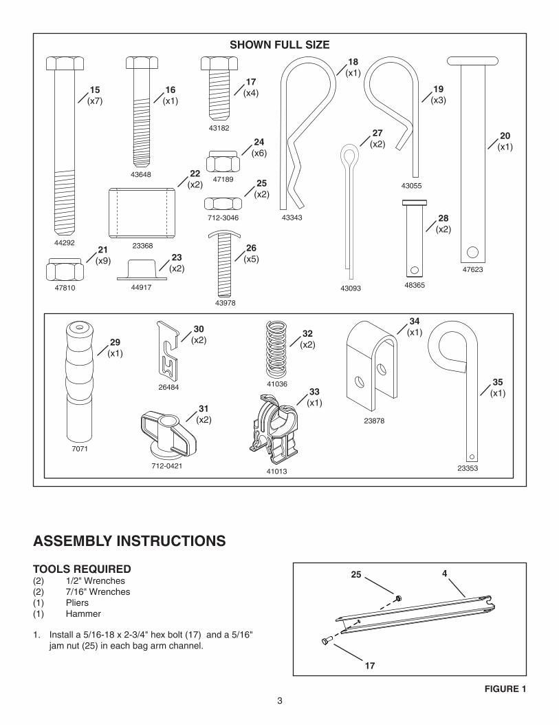
assemBlY InsTruCTIons
Install a 5/16-18 x 2-3/4" hex bolt (17) and a 5/16" 1. jam nut (25) in each bag arm channel.
44292
43648
43182
43343
47810 44917
23368
47189
712-3046
7071
26484
712-0421
41036
43978
43093
43055
47623
48365
41013 23353
23878
15(x7)
16(x1)
17(x4)
24(x6)
18(x1)
27(x2)
26(x5)
19(x3)
28(x2)
20(x1)
32(x2)
31(x2)
33(x1)
34(x1)
35(x1)
29(x1)
30(x2)
25(x2)
21(x9)
22(x2)
23(x2)
sHown Full sIZe
FIGure 1
17
425Tools reQuIreD(2) 1/2" Wrenches(2) 7/16" Wrenches(1) Pliers(1) Hammer

4
Slide the bag arm channels (4) into the sweeper 2. housingasshowninfigure2.Securethemtothesweeper housing with a 5/16-18 x 2-1/2" hex bolt (15) and 5/16" nylock nut (21). Tighten bolt until snug. Do not overtighten.
Secure each bag arm channel to the side of the 3. sweeper housing with a plastic wing nut (31) installed ontotheboltassembledinstep1.Seefigure3.Insert a pivot rod retainer (30) down into the end of 4. eachbagarmchannel.Seefigure3.Install a compression spring (32) into the bottom of 5. each of the pivot rod retainers to secure them to the bagarmchannels.Seefigure3.
Attach the drawbar (14) to the sweeper by fastening 6. a drawbar bracket (8) above and below the drawbar using three 5/16" x 2-1/2" hex bolts (15) and 5/16" nylocknuts(21).Seefigure4.
Lock the drawbar into position by inserting a 3/8" x 3" 7. hitch pin (20) into the center hole and securing it with a3/32"cotterpin(19).Seefigure5.
Attach the hitch bracket (12) and straight hitch bracket 8. (13) to the drawbar using two 5/16" x 2-1/2" hex bolts (15)and5/16"nylocknuts(21).Seefigure6.Assemble a 3/8" x 3" hitch pin (35) and two 3/4" 9. spacers (22) to the hitch brackets. Secure them in placewitha3/32"haircotterpin(18).Seefigure6.
FIGure 2
FIGure 3
FIGure 4
FIGure 5
20
19
8
15
14
21
8
FIGure 6
21
13
12
15
35
22
18
154
21
31
30
32

5
FIGure 8
FIGure 7
Slidethebagframetube(1)throughthefrontflapin10. thebottomofthebag.Seefigure7.Slidethetwolowerhoppertubes(10)intotheflapsat11. thefrontofthehopperbagasshowninfigure7.
Install a rear hopper tube (11) onto the ends of the 12. lower hopper tubes (10) making sure the holes in the rearhoppertubearefacingupasshowninfigure8.Secure the rear hopper tube (11) to the lower hopper 13. tubes (10) with two 1/4" x 1" curved head bolts (26) and1/4"nylocknuts(24).Seefigure8.
noTe: Hopper bag (3) not shown for clarity.
Slidethefrontflapsofthehopperbagupontothe14. front of the lower hopper tubes. Secure the bag frame tube to the lower hopper tubes using two clevis pins (28)andhairpins(19).Seefigure9.
noTe:Besurefrontflapsofhopperbagarepositionedabove clevis pins.
Snap the sides of the bag to the bottom of the bag at 15. the front corners .
10
24
24
11
10
10
26
26
1
28
19
FIGure 9
FIGure 10
1126
26
24
24
6
6
Install a rear hopper tube (11) onto the two upper 16. hoppertubes(6).Seefigure10.Secure the upper hopper tubes (6) to the rear hopper 17. tube (11) using two 1/4" x 1" curved head bolts (26) and 1/4" nylock nuts (24). Bolt heads should face up asshowninfigure10.
6FIGure 12
FIGure 13
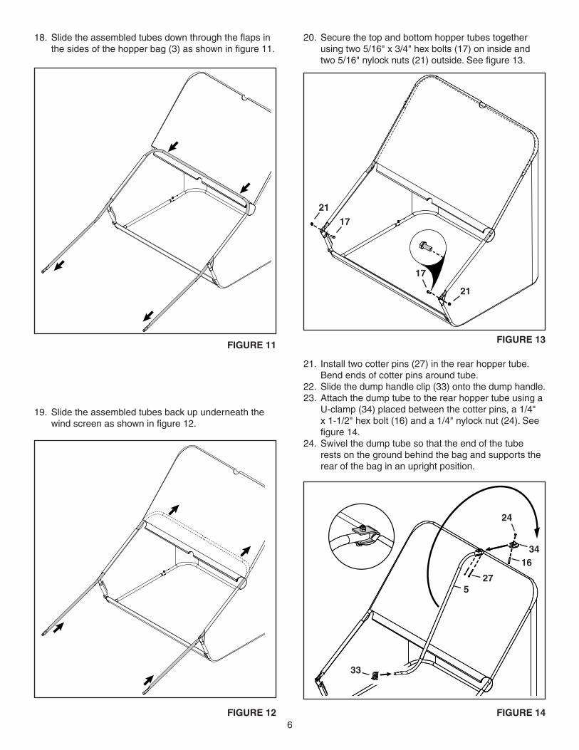
Slidetheassembledtubesdownthroughtheflapsin18. thesidesofthehopperbag(3)asshowninfigure11.
Slide the assembled tubes back up underneath the 19. windscreenasshowninfigure12.
17
17
21
21
FIGure 14
24
27
1634
5
33
Install two cotter pins (27) in the rear hopper tube. 21. Bend ends of cotter pins around tube.Slide the dump handle clip (33) onto the dump handle.22. Attach the dump tube to the rear hopper tube using a 23. U-clamp (34) placed between the cotter pins, a 1/4" x 1-1/2" hex bolt (16) and a 1/4" nylock nut (24). See figure14.Swivel the dump tube so that the end of the tube 24. rests on the ground behind the bag and supports the rear of the bag in an upright position.
FIGure 11
Secure the top and bottom hopper tubes together 20. using two 5/16" x 3/4" hex bolts (17) on inside and two5/16"nylocknuts(21)outside.Seefigure13.
7
FIGure 17
FIGure 18
FIGure 15
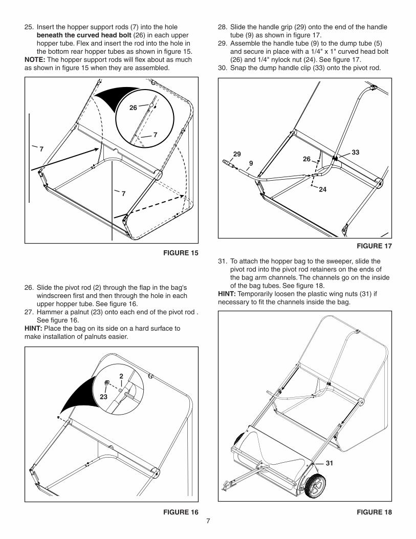
Slide the handle grip (29) onto the end of the handle 28. tube(9)asshowninfigure17.Assemble the handle tube (9) to the dump tube (5) 29. and secure in place with a 1/4" x 1" curved head bolt (26)and1/4"nylocknut(24).Seefigure17.Snap the dump handle clip (33) onto the pivot rod.30.
To attach the hopper bag to the sweeper, slide the 31. pivot rod into the pivot rod retainers on the ends of the bag arm channels. The channels go on the inside ofthebagtubes.Seefigure18.
HInT: Temporarily loosen the plastic wing nuts (31) if necessarytofitthechannelsinsidethebag.
31
Insert the hopper support rods (7) into the hole 25. beneath the curved head bolt (26) in each upper hopper tube. Flex and insert the rod into the hole in thebottomrearhoppertubesasshowninfigure15.
noTe: Thehoppersupportrodswillflexaboutasmuchasshowninfigure15whentheyareassembled.
FIGure 16
2
23
Slidethepivotrod(2)throughtheflapinthebag's26. windscreenfirstandthenthroughtheholeineachupperhoppertube.Seefigure16.Hammer a palnut (23) onto each end of the pivot rod . 27. Seefigure16.
HInT: Place the bag on its side on a hard surface to make installation of palnuts easier.
7
7
26
7
299
26
24
33
8
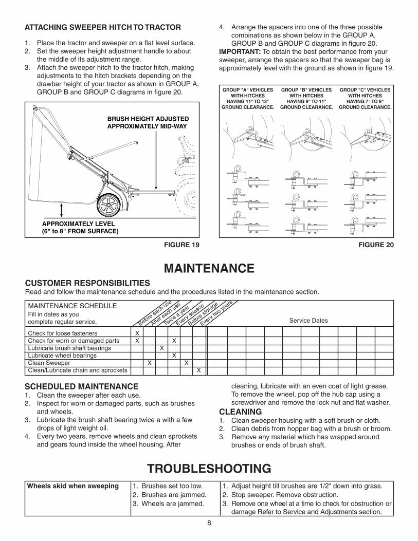
aTTaCHInG sweePer HITCH To TraCTor
Placethetractorandsweeperonaflatlevelsurface.1. Set the sweeper height adjustment handle to about 2. the middle of its adjustment range. Attach the sweeper hitch to the tractor hitch, making 3. adjustments to the hitch brackets depending on the drawbar height of your tractor as shown in GROUP A, GROUPBandGROUPCdiagramsinfigure20. GrouP "B" VeHICles
wITH HITCHes HaVInG 9" To 11"
GrounD ClearanCe.
GrouP "a" VeHICles wITH HITCHes
HaVInG 11" To 13" GrounD ClearanCe.
GrouP "C" VeHICles wITH HITCHes
HaVInG 7" To 9" GrounD ClearanCe.
APPROXIMATELY LEVEL(6" to 8" FROM SURFACE)
BRUSH HEIGHT ADJUSTEDAPPROXIMATELY MID-WAY
TrouBlesHooTInGwheels skid when sweeping 1. Brushes set too low. 1. Adjust height till brushes are 1/2" down into grass.
2. Brushes are jammed. 2. Stop sweeper. Remove obstruction.3. Wheels are jammed. 3. Remove one wheel at a time to check for obstruction or
damage Refer to Service and Adjustments section.
FIGure 19 FIGure 20
Arrange the spacers into one of the three possible 4. combinations as shown below in the GROUP A, GROUPBandGROUPCdiagramsinfigure20.
ImPorTanT: To obtain the best performance from your sweeper, arrange the spacers so that the sweeper bag is approximatelylevelwiththegroundasshowninfigure19.
MAINTENANCE SCHEDULE Fill in dates as you complete regular service.
Check for loose fasteners X Check for worn or damaged parts X X Lubricate brush shaft bearings X Lubricate wheel bearings X Clean Sweeper X X Clean/Lubricate chain and sprockets X
Before each use
After e
ach use
Twice
a year
Every
seaso
n
Before storage
Every
two ye
ars
Service Dates
CusTomer resPonsIBIlITIesRead and follow the maintenance schedule and the procedures listed in the maintenance section.
maInTenanCe
sCHeDuleD maInTenanCeClean the sweeper after each use.1. Inspect for worn or damaged parts, such as brushes 2. and wheels.Lubricate the brush shaft bearing twice a with a few 3. drops of light weight oil.Every two years, remove wheels and clean sprockets 4. and gears found inside the wheel housing. After
cleaning, lubricate with an even coat of light grease. To remove the wheel, pop off the hub cap using a screwdriverandremovethelocknutandflatwasher.
CleanInGClean sweeper housing with a soft brush or cloth.1. Clean debris from hopper bag with a brush or broom.2. Remove any material which has wrapped around 3. brushes or ends of brush shaft.
9
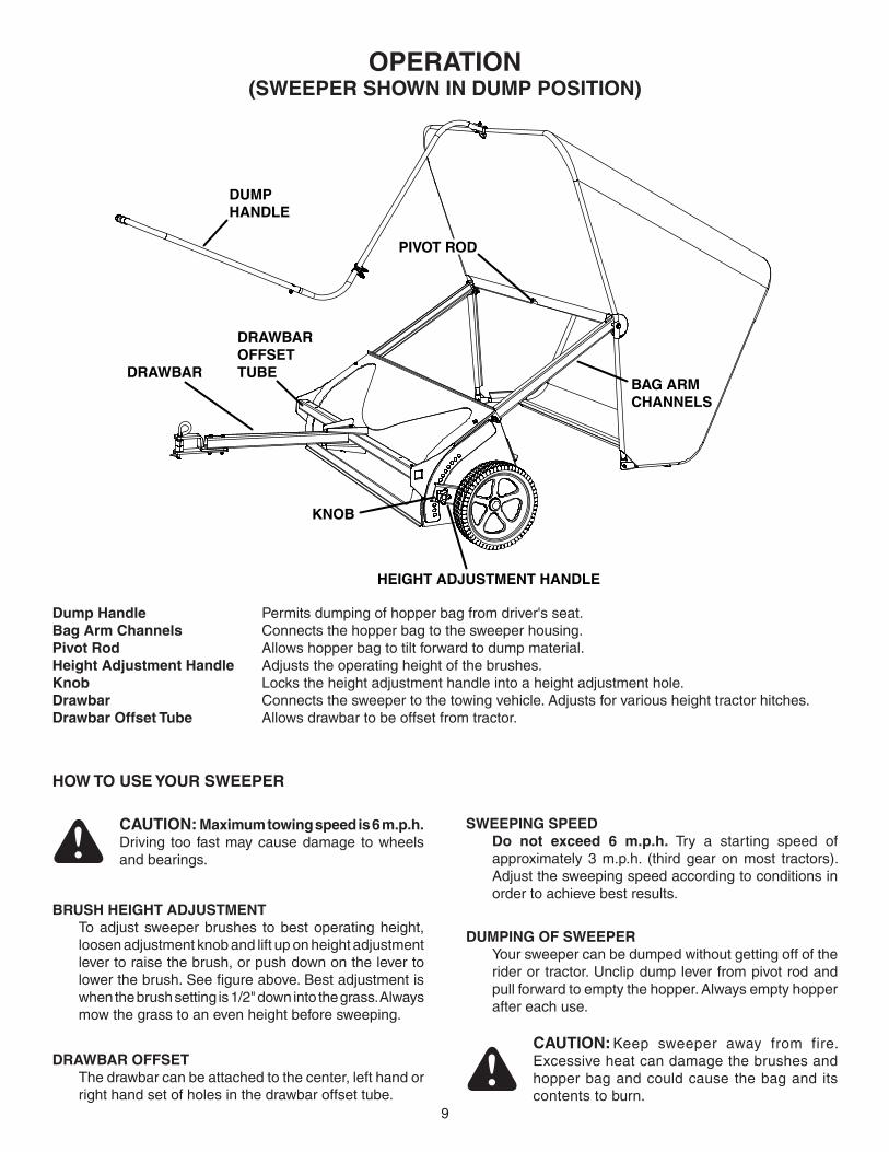
oPeraTIon(sweePer sHown In DumP PosITIon)
DUMPHANDLE
HEIGHT ADJUSTMENT HANDLE
BAG ARMCHANNELS
KNOB
PIVOT ROD
DRAWBAR
DRAWBAROFFSET TUBE
Dump Handle Permits dumping of hopper bag from driver's seat.Bag arm Channels Connects the hopper bag to the sweeper housing.Pivot rod Allows hopper bag to tilt forward to dump material.Height adjustment Handle Adjusts the operating height of the brushes.Knob Locks the height adjustment handle into a height adjustment hole.Drawbar Connects the sweeper to the towing vehicle. Adjusts for various height tractor hitches.Drawbar offset Tube Allows drawbar to be offset from tractor.
How To use Your sweePer
BrusH HeIGHT aDJusTmenT To adjust sweeper brushes to best operating height,
loosen adjustment knob and lift up on height adjustment lever to raise the brush, or push down on the lever to lowerthebrush.Seefigureabove.Bestadjustmentiswhen the brush setting is 1/2" down into the grass. Always mow the grass to an even height before sweeping.
DumPInG oF sweePer Your sweeper can be dumped without getting off of the
rider or tractor. Unclip dump lever from pivot rod and pull forward to empty the hopper. Always empty hopper after each use.
DrawBar oFFseT The drawbar can be attached to the center, left hand or
right hand set of holes in the drawbar offset tube.
CauTIon: Keep sweeper away from fire. Excessive heat can damage the brushes and hopper bag and could cause the bag and its contents to burn.
CauTIon: maximum towing speed is 6 m.p.h. Driving too fast may cause damage to wheels and bearings.
sweePInG sPeeD Do not exceed 6 m.p.h. Try a starting speed of
approximately 3 m.p.h. (third gear on most tractors). Adjust the sweeping speed according to conditions in order to achieve best results.
10
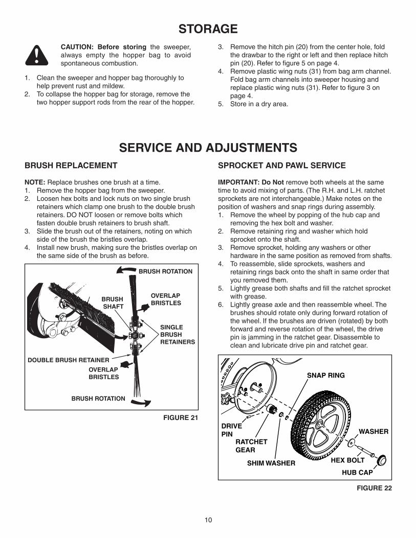
BrusH rePlaCemenT
noTe: Replace brushes one brush at a time.Remove the hopper bag from the sweeper.1. Loosen hex bolts and lock nuts on two single brush 2. retainers which clamp one brush to the double brush retainers. DO NOT loosen or remove bolts which fasten double brush retainers to brush shaft.Slide the brush out of the retainers, noting on which 3. side of the brush the bristles overlap.Install new brush, making sure the bristles overlap on 4. the same side of the brush as before.
serVICe anD aDJusTmenTssProCKeT anD Pawl serVICe
ImPorTanT: Do not remove both wheels at the same time to avoid mixing of parts. (The R.H. and L.H. ratchet sprockets are not interchangeable.) Make notes on the position of washers and snap rings during assembly.
Remove the wheel by popping of the hub cap and 1. removing the hex bolt and washer. Remove retaining ring and washer which hold 2. sprocket onto the shaft.Remove sprocket, holding any washers or other 3. hardware in the same position as removed from shafts.To reassemble, slide sprockets, washers and 4. retaining rings back onto the shaft in same order that you removed them.Lightlygreasebothshaftsandfilltheratchetsprocket5. with grease.Lightly grease axle and then reassemble wheel. The 6. brushes should rotate only during forward rotation of the wheel. If the brushes are driven (rotated) by both forward and reverse rotation of the wheel, the drive pin is jamming in the ratchet gear. Disassemble to clean and lubricate drive pin and ratchet gear.
sToraGe
Clean the sweeper and hopper bag thoroughly to 1. help prevent rust and mildew.To collapse the hopper bag for storage, remove the 2. two hopper support rods from the rear of the hopper.
CauTIon: Before storing the sweeper, always empty the hopper bag to avoid spontaneous combustion.
Remove the hitch pin (20) from the center hole, fold 3. the drawbar to the right or left and then replace hitch pin(20).Refertofigure5onpage4.Remove plastic wing nuts (31) from bag arm channel. 4. Fold bag arm channels into sweeper housing and replaceplasticwingnuts(31).Refertofigure3onpage 4.Store in a dry area.5.
HEX BOLT
WASHER
HUB CAPSHIM WASHER
SNAP RING
DRIVE PIN
RATCHET GEAR
BRUSH ROTATION
BRUSH ROTATION
OVERLAP BRISTLES
OVERLAP BRISTLES
SINGLE BRUSH RETAINERS
DOUBLE BRUSH RETAINER
BRUSH SHAFT
FIGure 21
FIGure 22
11
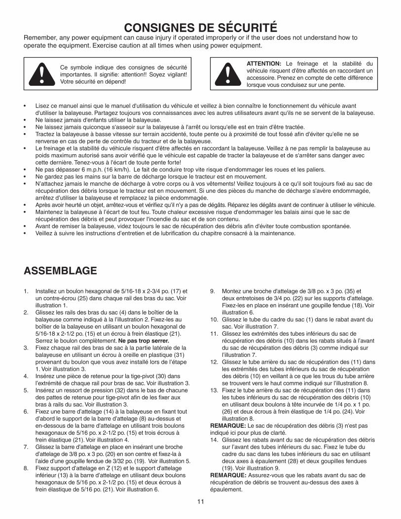
ConsIGnes De sÉCurITÉRemember, any power equipment can cause injury if operated improperly or if the user does not understand how to operate the equipment. Exercise caution at all times when using power equipment.
Ce symbole indique des consignes de sécurité importantes. Il signifie: attention!! Soyez vigilant!Votresécuritéendépend!
aTTenTIon: Le freinage et la stabilité du véhicule risquent d'être affectés en raccordant un accessoire.Prenezencomptedecettedifférencelorsquevousconduisezsurunepente.
Lisezcemanuelainsiquelemanueld'utilisationduvéhiculeetveillezàbienconnaîtrelefonctionnementduvéhiculeavant•d'utiliserlabalayeuse.Partageztoujoursvosconnaissancesaveclesautresutilisateursavantqu'ilsneseserventdelabalayeuse.Nelaissezjamaisd'enfantsutiliserlabalayeuse.•Nelaissezjamaisquiconques'asseoirsurlabalayeuseàl'arrêtoulorsqu'elleestentraind'êtretractée.•Tractezlabalayeuseàbassevitessesurterrainaccidenté,toutepenteouàproximitédetoutfosséafind'éviterqu'ellenese•renverse en cas de perte de contrôle du tracteur et de la balayeuse.Lefreinageetlastabilitéduvéhiculerisquentd'êtreaffectésenraccordantlabalayeuse.Veillezànepasremplirlabalayeuseau•poidsmaximumautorisésansavoirvérifiéquelevéhiculeestcapabledetracterlabalayeuseetdes'arrêtersansdangeraveccettedernière.Tenez-vousàl'écartdetoutepenteforte!Ne pas dépasser 6 m.p.h. (16 km/h). Le fait de conduire trop vite risque d’endommager les roues et les paliers.•Negardezpaslesmainssurlabarrededéchargelorsqueletracteurestenmouvement.•N’attachezjamaislemanchededéchargeàvotrecorpsouàvosvêtements!Veilleztoujoursàcequ'ilsoittoujoursfixéausacde•récupération des débris lorsque le tracteur est en mouvement. Si une des pièces du manche de décharge s'avère endommagée, arrêtezd’utiliserlabalayeuseetremplacezlapièceendommagée.Aprèsavoirheurtéunobjet,arrêtez-vousetvérifiezqu’iln’yapasdedégâts.Réparezlesdégâtsavantdecontinueràutiliserlevéhicule.•Maintenezlabalayeuseàl’écartdetoutfeu.Toutechaleurexcessiverisqued'endommagerlesbalaisainsiquelesacde•récupération des débris et peut provoquer l'incendie du sac et de son contenu.Avantderemiserlabalayeuse,videztoujourslesacderécupérationdesdébrisafind'évitertoutecombustionspontanée.•Veillezàsuivrelesinstructionsd’entretienetdelubrificationduchapitreconsacréàlamaintenance.•
assemBlaGe
Installezunboulonhexagonalde5/16-18x2-3/4po.(17)et1. un contre-écrou (25) dans chaque rail des bras du sac. Voir illustration 1.Glissezlesrailsdesbrasdusac(4)dansleboîtierdela2. balayeusecommeindiquéàlal’illustration2.Fixez-lesauboîtierdelabalayeuseenutilisantunboulonhexagonalde5/16-18x2-1/2po.(15)etunécrouàfreinélastique(21).Serrezlebouloncomplètement.ne pas trop serrer.Fixezchaqueraildesbrasdesacàlapartielatéraledela3. balayeuseenutilisantunécrouàoreilleenplastique(31)provenantduboulonquevousavezinstallélorsdel’étape1. Voir illustration 3. Insérezunepiècederetenuepourlatige-pivot(30)dans4. l’extrémité de chaque rail pour bras de sac. Voir illustration 3. Insérezunressortdepression(32)danslebasdechacune5. despattesderetenuepourtige-pivotafindelesfixerauxbrasàrailsdusac.Voirillustration3.Fixezunebarred’attelage(14)àlabalayeuseenfixanttout6. d’abord le support de la barre d’attelage (8) au-dessus et en-dessous de la barre d’attelage en utilisant trois boulons hexagonauxde5/16po.x2-1/2po.(15)ettroisécrousàfrein élastique (21). Voir illustration 4.Glissezlabarred’attelageenplaceeninsérantunebroche7. d’attelagede3/8po.x3po.(20)ensoncentreetfixez-laàl’aide d’une goupille fendue de 3/32 po. (19). Voir illustration 5.Fixezsupportd’attelageenZ(12)etlesupportd'attelage8. inférieur(13)àlabarred’attelageenutilisantdeuxboulonshexagonauxde5/16po.x2-1/2po.(15)etdeuxécrousàfrein élastique de 5/16 po. (21). Voir illustration 6.
Montezunebroched'attelagede3/8po.x3po.(35)et9. deux entretoises de 3/4 po. (22) sur les supports d’attelage. Fixez-lesenplaceeninsérantunegoupillefendue(18).Voirillustration 6.Glissezletubeducadredusac(1)danslerabatavantdu10. sac. Voir illustration 7.Glissezlesextrémitésdestubesinférieursdusacde11. récupérationdesdébris(10)danslesrabatssituésàl’avantdu sac de récupération des débris (3) comme indiqué sur l’illustration 7. Glissezletubearrièredusacderécupérationdes(11)dans12. les extrémités des tubes inférieurs du sac de récupération desdébris(10)enveillantàcequelestrousdutubearrièrese trouvent vers le haut comme indiqué sur l’illustration 8.Fixezletubearrièredusacderécupérationdes(11)dans13. les tubes inférieurs du sac de récupération des débris (10) enutilisantdeuxboulonsàtêteincurvéede1/4po.x1po.(26)etdeuxécrousàfreinélastiquede1/4po.(24).Voirillustration 8.
remarQue: Le sac de récupération des débris (3) n'est pas indiqué ici pour plus de clarté.Glissezlesrabatsavantdusacderécupérationdesdébris14. surl’avantdestubesinférieursdusac.Fixezletubeducadre du sac dans les tubes inférieurs du sac en utilisant deuxaxesàépaulement(28)etdeuxgoupillesfendues(19). Voir illustration 9.
remarQue:Assurez-vousquelesrabatsavantdusacderécupérationdedébrissetrouventau-dessusdesaxesàépaulement.
12
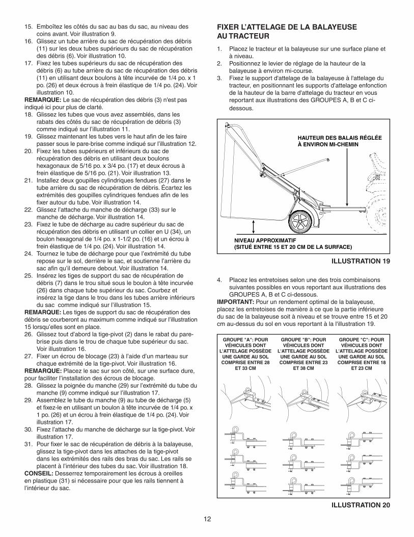
FIXer l’aTTelaGe De la BalaYeuse au TraCTeur
Placezletracteuretlabalayeusesurunesurfaceplaneet1. àniveau.Positionnezlelevierderéglagedelahauteurdela2. balayeuseàenvironmi-course.Fixezlesupportd'attelagedelabalayeuseàl'attelagedu3. tracteur, en positionnant les supports d’attelage enfonction de la hauteur de la barre d'attelage du tracteur en vous reportant aux illustrations des GROUPES A, B et C ci-dessous.
NIVEAU APPROXIMATIF (SITUÉ ENTRE 15 ET 20 CM DE LA SURFACE)
HAUTEUR DES BALAIS RÉGLÉE À ENVIRON MI-CHEMIN
IllusTraTIon 19
GrouPe "B": Pour VÉHICules DonT
l'aTTelaGe PossÈDe une GarDe au sol ComPrIse enTre 23
eT 38 Cm
GrouPe "a": Pour VÉHICules DonT
l'aTTelaGe PossÈDe une GarDe au sol ComPrIse enTre 28
eT 33 Cm
GrouPe "C": Pour VÉHICules DonT
l'aTTelaGe PossÈDe une GarDe au sol ComPrIse enTre 18
eT 23 Cm
IllusTraTIon 20
Placezlesentretoisesselonunedestroiscombinaisons4. suivantes possibles en vous reportant aux illustrations des GROUPES A, B et C ci-dessous.
ImPorTanT: Pour un rendement optimal de la balayeuse, placezlesentretoisesdemanièreàcequelapartieinférieuredusacdelabalayeusesoitàniveauetsetrouveentre15et20cmau-dessusdusolenvousreportantàlal'illustration19.
Emboîtezlescôtésdusacaubasdusac,auniveaudes15. coins avant. Voir illustration 9.Glissezuntubearrièredusacderécupérationdesdébris16. (11) sur les deux tubes supérieurs du sac de récupération des débris (6). Voir illustration 10.Fixezlestubessupérieursdusacderécupérationdes17. débris (6) au tube arrière du sac de récupération des débris (11)enutilisantdeuxboulonsàtêteincurvéede1/4po.x1po.(26)etdeuxécrousàfreinélastiquede1/4po.(24).Voirillustration 10.
remarQue: Le sac de récupération des débris (3) n'est pas indiqué ici pour plus de clarté.Glissezlestubesquevousavezassemblés,dansles18. rabats des côtés du sac de récupération de débris (3) comme indiqué sur l’illustration 11. Glissezmaintenantlestubesverslehautafindelesfaire19. passer sous le pare-brise comme indiqué sur l’illustration 12.Fixezlestubessupérieursetinférieursdusacde20. récupération des débris en utilisant deux boulons hexagonauxde5/16po.x3/4po.(17)etdeuxécrousàfrein élastique de 5/16 po. (21). Voir illustration 13.Installezdeuxgoupillescylindriquesfendues(27)dansle21. tubearrièredusacderécupérationdedébris.Écartezlesextrémitésdesgoupillescylindriquesfenduesafindelesfixerautourdutube.Voirillustration14.Glissezl’attachedumanchededécharge(33)surle22. manche de décharge. Voir illustration 14.Fixezletubededéchargeaucadresupérieurdusacde23. récupération des débris en utilisant un collier en U (34), un boulonhexagonalde1/4po.x1-1/2po.(16)etunécrouàfrein élastique de 1/4 po. (24). Voir illustration 14.Tournezletubededéchargepourquel’extrémitédutube24. repose sur le sol, derrière le sac, et soutienne l’arrière du sacafinqu’ildemeuredebout.Voirillustration14.Insérezlestigesdesupportdusacderécupérationde25. débris(7)dansletrousituésousleboulonàtêteincurvée(26)danschaquetubesupérieurdusac.Courbezetinsérezlatigedansletroudanslestubesarrièreinférieursdu sac comme indiqué sur l’illustration 15.
remarQue: Les tiges de support du sac de récupération des débris se courberont au maximum comme indiqué sur l’illustration 15 lorsqu’elles sont en place.Glisseztoutd’abordlatige-pivot(2)danslerabatdupare-26. brise puis dans le trou de chaque tube supérieur du sac. Voir illustration 16. Fixerunécroudeblocage(23)àl’aided’unmarteausur27. chaque extrémité de la tige-pivot. Voir illustration 16.
remarQue: Placezlesacsursoncôté,surunesurfacedure,pour faciliter l’installation des écrous de blocage. Glissezlapoignéedumanche(29)surl’extrémitédutubedu28. manche (9) comme indiqué sur l’illustration 17.Assemblezletubedumanche(9)autubededécharge(5)29. etfixez-leenutilisantunboulonàtêteincurvéede1/4po.x1po.(26)etunécrouàfreinélastiquede1/4po.(24).Voirillustration 17.Fixezl’attachedumanchededéchargesurlatige-pivot.Voir30. illustration 17.Pourfixerlesacderécupérationdedébrisàlabalayeuse,31. glissezlatige-pivotdanslesattachesdelatige-pivotdans les extrémités des rails des bras du sac. Les rails se placentàl’intérieurdestubesdusac.Voirillustration18.
ConseIl: Desserreztemporairementlesécrousàoreillesenplastique(31)sinécessairepourquelesrailstiennentàl’intérieur du sac.
13
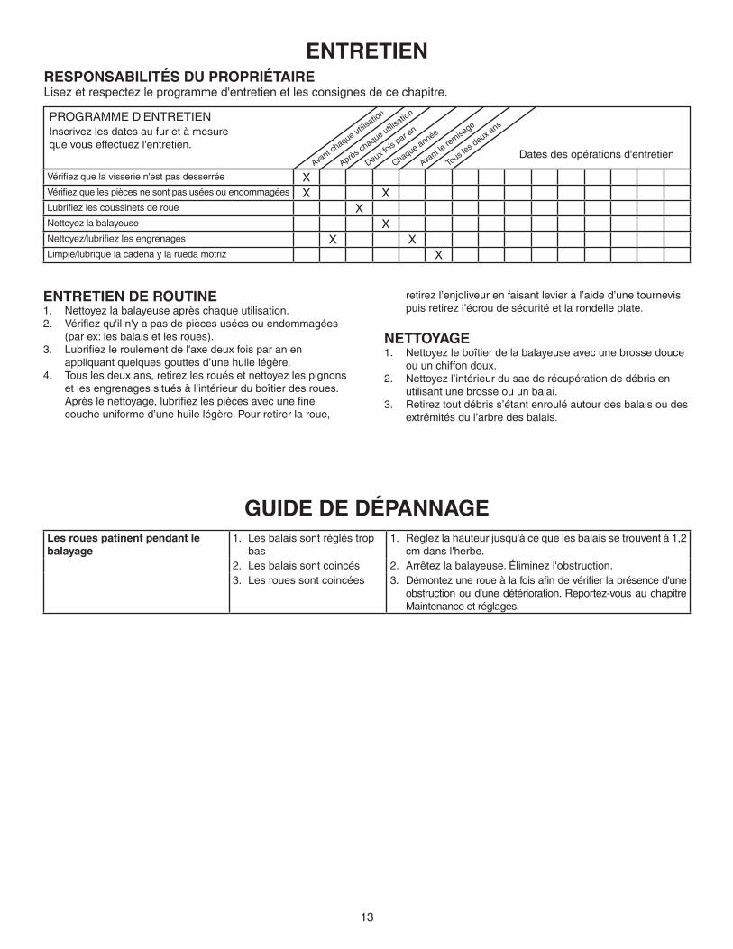
GuIDe De DÉPannaGeles roues patinent pendant le balayage
1. Les balais sont réglés trop bas
1. Réglezlahauteurjusqu'àcequelesbalaissetrouventà1,2cm dans l'herbe.
2. Les balais sont coincés 2. Arrêtezlabalayeuse.Éliminezl'obstruction.3. Les roues sont coincées 3. Démontezuneroueàlafoisafindevérifierlaprésenced'une
obstructionoud'unedétérioration.Reportez-vousauchapitreMaintenance et réglages.
PROGRAMME D'ENTRETIEN Inscrivezlesdatesaufuretàmesure quevouseffectuezl'entretien.
Avant c
haque utilisatio
n
Après chaque utilis
ation
Deux fois
par an
Chaque année
Avant le
remisa
ge
Tous l
es deux a
ns
Dates des opérations d'entretien
resPonsaBIlITÉs Du ProPrIÉTaIreLisezetrespectezleprogrammed'entretienetlesconsignesdecechapitre.
enTreTIen
enTreTIen De rouTIneNettoyezlabalayeuseaprèschaqueutilisation.1. Vérifiezqu'iln'yapasdepiècesuséesouendommagées2. (par ex: les balais et les roues).Lubrifiezleroulementdel'axedeuxfoisparanen3. appliquant quelques gouttes d’une huile légère.Touslesdeuxans,retirezlesrouésetnettoyezlespignons4. etlesengrenagessituésàl’intérieurduboîtierdesroues.Aprèslenettoyage,lubrifiezlespiècesavecunefinecouche uniforme d’une huile légère. Pour retirer la roue,
retirezl’enjoliveurenfaisantlevieràl’aided’unetournevispuisretirezl’écroudesécuritéetlarondelleplate.
neTToYaGeNettoyezleboîtierdelabalayeuseavecunebrossedouce1. ou un chiffon doux.Nettoyezl’intérieurdusacderécupérationdedébrisen2. utilisant une brosse ou un balai.Retireztoutdébriss’étantenrouléautourdesbalaisoudes3. extrémités du l’arbre des balais.
Vérifiezquelavisserien'estpasdesserrée XVérifiezquelespiècesnesontpasuséesouendommagées X XLubrifiezlescoussinetsderoue XNettoyezlabalayeuse XNettoyez/lubrifiezlesengrenages X XLimpie/lubriquelacadenaylaruedamotriz X
14
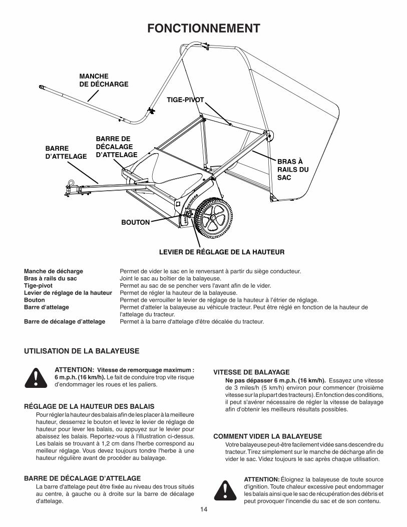
FonCTIonnemenT
MANCHE DE DÉCHARGE
LEVIER DE RÉGLAGE DE LA HAUTEUR
BRAS À RAILS DU SAC
BOUTON
TIGE-PIVOT
BARRE D’ATTELAGE
BARRE DE DÉCALAGE D’ATTELAGE
manche de décharge Permetdeviderlesacenlerenversantàpartirdusiègeconducteur.Bras à rails du sac Jointlesacauboîtierdelabalayeuse.Tige-pivot Permetausacdesepencherversl'avantafindelevider.levier de réglage de la hauteur Permet de régler la hauteur de la balayeuse.Bouton Permetdeverrouillerlelevierderéglagedelahauteuràl’étrierderéglage.Barre d'attelage Permet d'atteler la balayeuse au véhicule tracteur. Peut être réglé en fonction de la hauteur de l'attelage du tracteur.Barre de décalage d’attelage Permetàlabarred'attelaged'êtredécaléedutracteur.
uTIlIsaTIon De la BalaYeuse
rÉGlaGe De la HauTeur Des BalaIs Pourréglerlahauteurdesbalaisafindelesplaceràlameilleurehauteur,desserrezleboutonetlevezlelevierderéglagedehauteurpourleverlesbalais,ouappuyezsurlelevierpourabaissezlesbalais.Reportez-vousàl'illustrationci-dessus.Lesbalaissetrouvantà1,2cmdansl'herbecorrespondaumeilleurréglage.Vousdeveztoujours tondre l'herbeàunehauteur régulière avant de procéder au balayage.
aTTenTIon:Éloignezlabalayeusedetoutesourced'ignition. Toute chaleur excessive peut endommager les balais ainsi que le sac de récupération des débris et peut provoquer l'incendie du sac et de son contenu.
CommenT VIDer la BalaYeuse Votre balayeuse peut-être facilement vidée sans descendre du tracteur.Tirezsimplementsurlemanchededéchargeafindeviderlesac.Videztoujourslesacaprèschaqueutilisation.
Barre De DÉCalaGe D’aTTelaGe Labarred'attelagepeutêtrefixéeauniveaudestroussituésau centre, àgaucheouàdroite sur la barrededécalaged'attelage.
VITesse De BalaYaGe ne pas dépasser 6 m.p.h. (16 km/h). Essayezunevitesse
de 3 miles/h (5 km/h) environ pour commencer (troisième vitesse sur la plupart des tracteurs). En fonction des conditions, il peut s'avérer nécessaire de régler la vitesse de balayage afind'obtenirlesmeilleursrésultatspossibles.
aTTenTIon: Vitesse de remorquage maximum : 6 m.p.h. (16 km/h). Le fait de conduire trop vite risque d’endommager les roues et les paliers.

15
remPlaCemenT Des BalaIs
remarQue:Leremplacementdesbalaisdoits'effectuerunàla fois.Démontezlesacderécupérationdesdébrisdela1. balayeuse.Desserrezlesboulonshexagonauxetlescontre-écrous2. desdeuxpattesdefixationquimaintiennentunseulbalaisur le dispositif retenant les deux balais. NE PAS desserrer ni démonter les boulons qui maintiennent le dispositif de retenue des deux balais sur l'axe des balais. Faitesglisserlebalaiendehorsdespattesdefixationen3. notant le côté de du balai sur lequel se chevauchent les soies. Installezunnouveaubalaienvousassurantquelessoies4. se chevauchent du même côté qu'auparavant.
maInTenanCe eT rÉGlaGesenTreTIen Des enGrenaGes Des roues eT PIGnons
ImPorTanT: ne Pas démonter les deux roues simultanément afind'éviterd'intervertirdespièces.(Lesengrenagesdroitetgauchedespignonsnesontpasinterchangeables.)Preneznotedelapositiondesrondellesetdesanneauxàressortpendant le démontage.Retirezlaroueenenlevanttoutd'abordl’enjoliveurpuisle1. boulon hexagonal et la rondelle.Retirezlesbaguesderetenueetlesrondellesqui2. maintiennent les pignons sur les axes. Retirezlespignonsdesaxesenveillantàmaintenirles3. rondellesetlesautrespiècesenveillantàlesgarderdansla même position lorsque vous les retirer des axes. Pourprocéderauremontage,glissezlespignons,les4. rondellesetlesbaguesderetenueànouveausurl’axedanslemêmeordrequelorsquevouslesavezretirés.Graissezlégèrementlesdeuxaxesetremplissezlepignon5. avec de la graisse. Graissezlégèrementl’axepuisremettezenplacelaroue.6. Les balais doivent seulement tourner pendant la rotation 7. versl’avantdelaroue.Silesbalaissontentraînés(enrotation) aussi bien lors de la rotation en marche avant qu’enmarchearrièredelaroue,lagoupilled'entraînementsetrouvecoincéedansl'engrenagedupignon.Démontezl'ensembleafindenettoyeretdegraisserlagoupilled'entraînementainsiquel'engrenagedupignon.
remIsaGe
Nettoyezparfaitementlabalayeuseetlesacafinde1. prévenir toute apparition de rouille et de moisissure.Pour plier le sac de récupération des débris en vue de son 2. entreposage,démontezlesdeuxtigesdesupportsituéesàl'arrière du sac.
aTTenTIon : avant de remiser la balayeuse, videztoujourslesacderécupérationdesdébrisafind'évitertoutecombustionspontanée.
Retirezlabroched’attelage(20)dutroucentral,déplacez3. labarred'attelageversladroiteoulagauchepuisremettezenplacelabroched’attelage(20).Reportez-vousàl’illustration 5 de la page 4.Retirezlesécrousàoreillesenplastique(31)desrailsdes4. brasdusac.Repliezlesbrasàrailsdusacversl’intérieurduboîtierdelabalayeuseetremettezenplacelesécrousàoreillesenplastique(31).Reportez-vousàl’illustration3de la page 4.Remisezlabalayeusedansunendroitsec.5.
BOULON HEXAGONAL
RONDELLE
ENJOLIVEUR
RONDELLE DE CALAGE
ANNEAUX À RESSORT
GOUPILLE D'ENTRAÎNEMENT
ENGRENAGE
SENS DE ROTATION DU BALAI
SENS DE ROTATION DU BALAI
LES SOIES SE CHEVAUCHENT
LES SOIES SE CHEVAUCHENT
PATTES DE FIXATION D'UN BALAI
PATTE DE FIXATION DES DEUX BALAIS
AXE DU BALAI
IllusTraTIon 21
IllusTraTIon 22
16
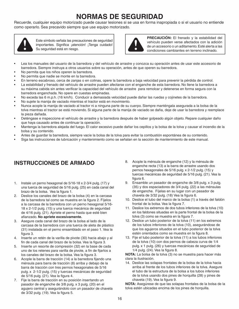
normas De seGurIDaDRecuerde,cualquierequipomotorizadopuedecausarlesionessiseusaenformainapropiadaosielusuarionoentiendecomooperarlo.Seaprecavidosiemprequeuseequipomotorizado.
Este símbolo señala las precauciones de seguridad importantes. Significa ¡atención! ¡Tenga cuidado!Su seguridad está en riesgo.
PreCauCIÓn: El frenado y la estabilidad del vehículo pueden verse afectados con la adición de un accesorio o un aditamento. Esté alerta a las condiciones cambiantes en terreno inclinado.
Lealosmanualesdelusuariodelabarredoraydelvehículodearrastreyconozcasuoperaciónantesdeusaresteaccesoriode•barredora. Siempre instruya a otros usuarios sobre su operación, antes de que operen su barredora.No permita que los niños operen la barredora.•No permita que nadie se monte en la barredora.•Enterrenoescabroso,cercadezanjasoencolinas,operelabarredoraabajavelocidadparaprevenirlapérdidadecontrol.•La estabilidad y frenado del vehículo de arrastre pueden afectarse con el enganche de esta barredora. No llene la barredora a •sumáximacabidasinantesverificarlacapacidaddelvehículodearrastrepararemolcarydetenerseenformaseguraconlabarredora enganchada. No opere en cuestas empinadas.No exceda las 6 m.p.h. (16 km/h). Conducir a demasiada velocidad puede dañar las ruedas y cojinetes de la barredora. •No sujete la manija de vaciado mientras el tractor está en movimiento.•Nunca acople la manija de vaciado al tractor ni a ninguna parte de su cuerpo. Siempre manténgala asegurada a la bolsa de la •tolva mientras el tractor se está moviendo. Si alguna parte de la manija de vaciado se daña, deje de usar la barredora y reemplace lapiezadañada.Deténgase e inspeccione el vehículo de arrastre y la barredora después de haber golpeado algún objeto. Repare cualquier daño •que haya causado antes de continuar la operación.Mantenga la barredora alejada del fuego. El calor excesivo puede dañar los cepillos y la bolsa de la tolva y causar el incendio de la •bolsa y su contenido.Antes de guardar la barredora, siempre vacíe la bolsa de la tolva para evitar la combustión espontánea de su contenido.•Siga las instrucciones de lubricación y mantenimiento como se señalan en la sección de mantenimiento de este manual.•
InsTruCCIones De armaDo
Instale un perno hexagonal de 5/16-18 x 2-3/4 pulg. (17) y 1. una tuerca de seguridad de 5/16 pulg. (25) en cada canal del brazodelabolsa.Vealafigura1.Desliceloscanalesdelbrazodelabolsa(4)enlacarcasa2. delabarredoratalcomosemuestraenlafigura2.Fíjelosa la carcasa de la barredora con un perno hexagonal 5/16-18 x 2-1/2 pulg. (15) y una tuerca mecánica de seguridad de 4/16 pulg. (21). Apriete el perno hasta que esté bien afianzado.no apriete excesivamente.Asegurecadacanaldelbrazodelabolsaalladodela3. carcasa de la barredora con una tuerca de aleta de plástico (31) instalada en el perno ensamblado en el paso 1. Vea la figura3.Inserte un retén de la varilla de pivote (30) hacia abajo y al 4. findecadacanaldelbrazodelabolsa.Vealafigura3.Inserte un resorte de compresión (32) en la base de cada 5. unodelosretenesparavarilladepivote,afindefijarlosaloscanalesdelbrazodelabolsa.Vealafigura3.Acoplelabarradetracción(14)alabarredorafijandouna6. ménsula para barra de tracción (8) arriba y debajo de la barra de tracción con tres pernos hexagonales de 5/16 pulg. x 2-1/2 pulg. (15) y tuercas mecánicas de seguridad de5/16pulg.(21).Vealafigura4.Fije la barra de tracción en su posición insertando un 7. pasador de enganche de 3/8 pulg. x 3 pulg. (20) en el agujero central y asegurándolo con un pasador de chaveta de3/32pulg.(19).Vealafigura5.
Acople la ménsula de enganche (12) y la ménsula de 8. enganche recta (13) a la barra de arrastre usando dos pernos hexagonales de 5/16 pulg. x 2-1/2 pulg. (15) y tuercas mecánicas de seguridad de 5/16 pulg. (21). Vea la figura6.Ensamble un pasador de enganche de 3/8 pulg. x 3 pulg. 9. (35) y dos espaciadores de 3/4 pulg. (22) a las ménsulas de enganche. Fíjelas en su lugar con un pasador de chavetade3/32pulg.(18)Vealafigura6.Deslice el tubo del marco de la bolsa (1) a través del faldón 10. frontaldelabolsa.Vealafigura7.Deslice los extremos de dos tubos inferiores de la tolva (10) 11. en los faldones situadas en la parte frontal de la bolsa de la tolva(3)comosemuestraenlafigura7.Deslice un tubo posterior de la tolva (11) en los extremos 12. de los tubos inferiores de la tolva (10), asegurándose de que los agujeros situados en el tubo posterior de la tolva esténorientadoscomosemuestraenlafigura8.Fije el tubo posterior de la tolva (11) a los tubos inferiores 13. delatolva(10)condospernosdecabezacurvade1/4pulg. x 1 pulg. (26) y tuercas mecánicas de seguridad de 1/4pulg.(24).Vealafigura8.
noTa: La bolsa de la tolva (3) no se muestra para hacer más clara la ilustración.
Deslice las solapas frontales de la bolsa de la tolva hacia 14. arriba al frente de los tubos inferiores de la tolva. Asegure el tubo de la estructura de la bolsa a los tubos inferiores de la tolva usando dos pines de horquilla (28) y pines de chaveta(19).Vealafigura9.
noTa: Asegúrese de que las solapas frontales de la bolsa de la tolva estén ubicadas encima de los pines de horquilla.
17
Encaje los lados de la bolsa en la parte inferior de la bolsa 15. enlasesquinasfrontales.Vealafigura9.Deslice un tubo posterior de la tolva (11) sobre los dos 16. tubossuperioresdelatolva(6).Vealafigura10.Fije los tubos superiores de la tolva (6) al tubo posterior de 17. latolva(11)condospernosdecabezacurvade1/4pulg.x1 pulg. (26) y tuercas mecánicas de seguridad de 1/4 pulg. (24).Vealafigura10.Deslice los tubos ensamblados hacia abajo a través de las 18. solapas en los lados de la bolsa de la tolva (3) como se muestraenlafigura11.Deslice los tubos ensamblados nuevamente hacia arriba 19. por debajo de la pantalla de protección contra el viento comosemuestraenlafigura12.Fije los tubos superiores e inferiores de la tolva para unirlos 20. con dos pernos hexagonales de 5/16 pulg. x 3/4 pulg. (17) y tuercas mecánicas de seguridad de 5/16 pulg. (21). Vea lafigura13.Instale dos pines de chaveta (27) en el tubo posterior 21. de la tolva. Doble los extremos de los pines de chaveta alrededordeltubo.Vealafigura14.Deslicelaabrazaderadelapalancadevaciado(33)enla22. palancadevaciado.Vealafigura14.Monte el tubo de vaciado en el marco superior de la tolva 23. conunaabrazaderaenU(34),unpernohexagonalde1/4pulg. x 1-1/2 pulg. (16) y una tuerca mecánica de seguridad de1/4pulg.Vealafigura14.Gire el tubo de descarga de manera que el extremo del 24. tubo descanse sobre el suelo detrás de la bolsa y soporte la parte posterior de la bolsa en posición vertical. Vea la figura14.Inserte las varillas de soporte de la tolva (7) dentro del 25. agujerosituadodebajodelpernoconcabezacurva(26)en cada tubo superior de la tolva. Doble e inserte la varilla dentro del agujero en los tubos posteriores inferiores de la tolvacomosemuestraenlafigura15.
noTa: Las varillas de soporte de la tolva se doblarán como se muestraenlafigura15cuandoesténensambladas.
Deslice primero la varilla de pivote (2) a través de la solapa 26. en la pantalla de protección contra viento de la bolsa y luego a través del agujero en cada tubo superior de la tolva.Vealafigura16.Martilleunatuercadefijación(23)encadaunadelas27. varillasdepivote.Vealafigura16
ConseJo: Coloque la bolsa sobre uno de sus lados en una superficieduraparafacilitarlainstalacióndelastuercasdefijación.
Deslice la empuñadura de la manija (29) en el extremo del 28. tubodelamanija(9)comosemuestraenlafigura17.Monte el tubo de la manija (9) en el tubo de vaciado (5) 29. yfíjeloensulugarconunpernodecabezacurvade1/4pulg. x 1 pulg. (26) y una tuerca mecánica de seguridad de 1/4pulg.Vealafigura17.Encajelaabrazaderadelamanijadevaciadoenlavarilla30. depivote.Vealafigura17.Para conectar la bolsa de la tolva a la barredora, deslice la 31. varilla de pivote en los retenes de la varilla de pivote a los extremosdeloscanalesdelbrazodebolsa.Loscanalesvanalinteriordelostubosdelabolsa.Vealafigura18.
ConseJo: Aflojetemporalmentelastuercasdealetadeplástico (31) si es necesario de manera que los canales encajen dentro de la bolsa.
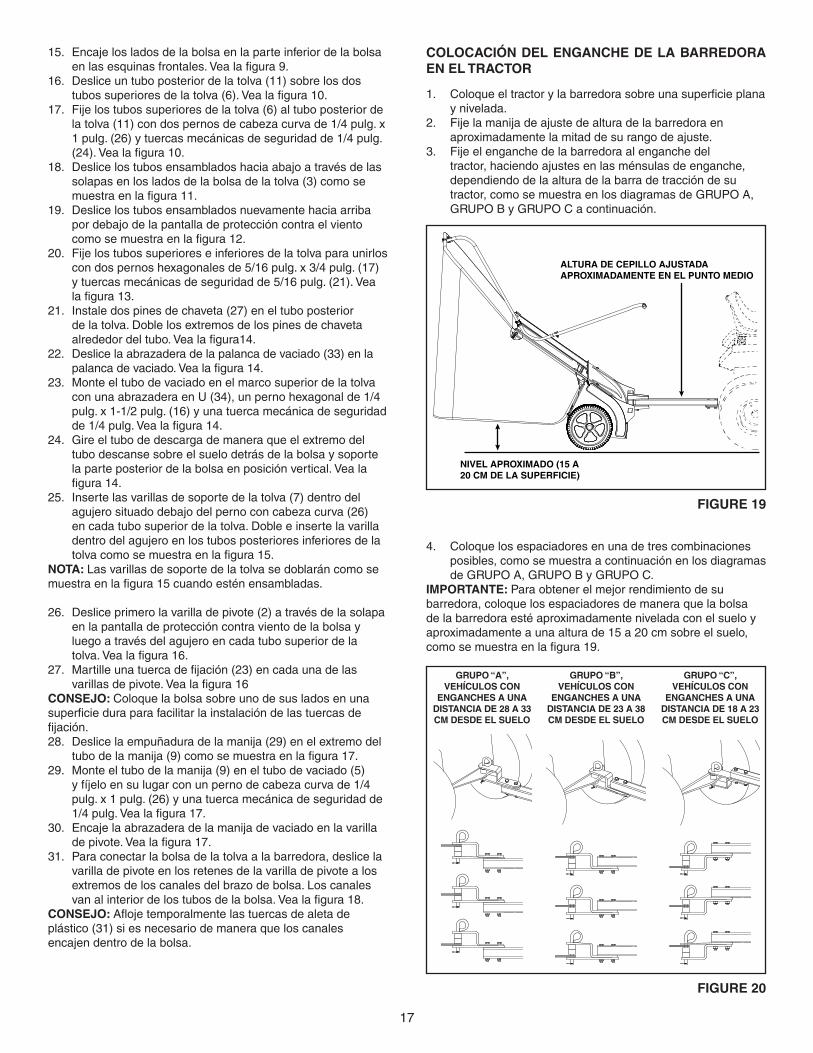
ColoCaCIÓn Del enGanCHe De la BarreDora en el TraCTor
Coloqueeltractorylabarredorasobreunasuperficieplana1. y nivelada. Fije la manija de ajuste de altura de la barredora en 2. aproximadamente la mitad de su rango de ajuste. Fije el enganche de la barredora al enganche del 3. tractor, haciendo ajustes en las ménsulas de enganche, dependiendo de la altura de la barra de tracción de su tractor, como se muestra en los diagramas de GRUPO A, GRUPO B y GRUPO C a continuación.
NIVEL APROXIMADO (15 A 20 CM DE LA SUPERFICIE)
ALTURA DE CEPILLO AJUSTADA APROXIMADAMENTE EN EL PUNTO MEDIO
FIGure 19
GruPo “B”, VeHÍCulos Con
enGanCHes a una DIsTanCIa De 23 a 38 Cm DesDe el suelo
GruPo “a”, VeHÍCulos Con
enGanCHes a una DIsTanCIa De 28 a 33 Cm DesDe el suelo
GruPo “C”, VeHÍCulos Con
enGanCHes a una DIsTanCIa De 18 a 23 Cm DesDe el suelo
FIGure 20
Coloque los espaciadores en una de tres combinaciones 4. posibles, como se muestra a continuación en los diagramas de GRUPO A, GRUPO B y GRUPO C.
ImPorTanTe: Para obtener el mejor rendimiento de su barredora, coloque los espaciadores de manera que la bolsa de la barredora esté aproximadamente nivelada con el suelo y aproximadamente a una altura de 15 a 20 cm sobre el suelo, comosemuestraenlafigura19.
18
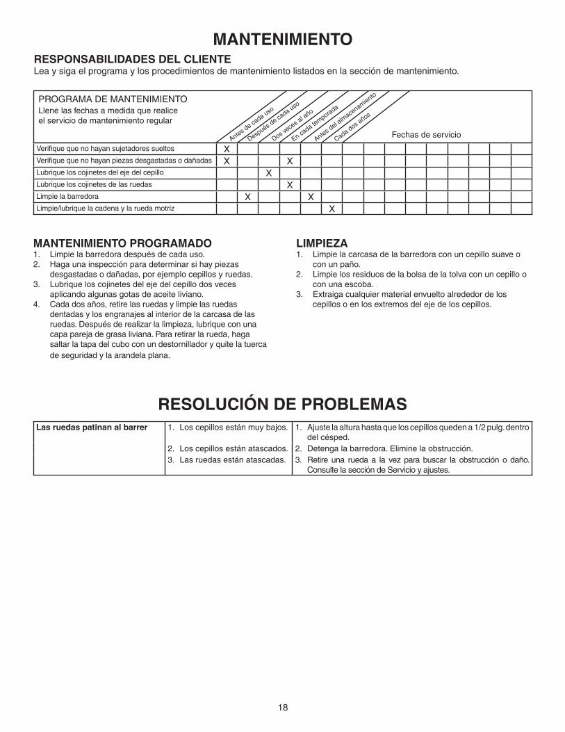
resoluCIÓn De ProBlemaslas ruedas patinan al barrer 1. Los cepillos están muy bajos. 1. Ajuste la altura hasta que los cepillos queden a 1/2 pulg. dentro
del césped.2. Los cepillos están atascados. 2. Detenga la barredora. Elimine la obstrucción.3. Las ruedas están atascadas. 3. Retireuna ruedaa la vezparabuscar laobstrucciónodaño.
Consulte la sección de Servicio y ajustes.
PROGRAMA DE MANTENIMIENTO Llene las fechas a medida que realice el servicio de mantenimiento regular
Antes de ca
da uso
Después d
e cada uso
Dos vece
s al a
ño
En cada te
mporada
Antes del a
lmace
namiento
Cada dos años
Fechas de servicio
resPonsaBIlIDaDes Del ClIenTeLea y siga el programa y los procedimientos de mantenimiento listados en la sección de mantenimiento.
manTenImIenTo
manTenImIenTo ProGramaDoLimpie la barredora después de cada uso.1. Hagaunainspecciónparadeterminarsihaypiezas2. desgastadas o dañadas, por ejemplo cepillos y ruedas. Lubrique los cojinetes del eje del cepillo dos veces 3. aplicando algunas gotas de aceite liviano.Cada dos años, retire las ruedas y limpie las ruedas 4. dentadas y los engranajes al interior de la carcasa de las ruedas.Despuésderealizarlalimpieza,lubriqueconunacapa pareja de grasa liviana. Para retirar la rueda, haga saltar la tapa del cubo con un destornillador y quite la tuerca de seguridad y la arandela plana.
lImPIeZaLimpie la carcasa de la barredora con un cepillo suave o 1. con un paño. Limpie los residuos de la bolsa de la tolva con un cepillo o 2. con una escoba.Extraiga cualquier material envuelto alrededor de los 3. cepillos o en los extremos del eje de los cepillos.
Verifiquequenohayansujetadoressueltos XVerifiquequenohayanpiezasdesgastadasodañadas X XLubrique los cojinetes del eje del cepillo XLubrique los cojinetes de las ruedas XLimpie la barredora X XLimpie/lubriquelacadenaylaruedamotriz X

19
oPeraCIÓn
PALANCA DE VACIADO
MANIJA DE AJUSTE DE LA ALTURA
CANALES DEL BRAZO DE LA BOLSA
PERILLA
VARILLA DE PIVOTE
BARRA DE TRACCIÓN
TUBO DE DESPLAZAMIENTO DE LA BARRA DE TRACCIÓN
Palanca de vaciado Permite vaciar la bolsa de la tolva desde el asiento del conductor.Canales del brazo de la bolsa Conecta la bolsa de la tolva a la carcasa de la barredora.Varilla de pivote Permite que la bolsa de la tolva se incline hacia delante para vaciar el material.manija de ajuste de la altura Ajusta la altura de operación de la barredora.Perilla Bloquea la manija de ajuste de la altura en un agujero de ajuste de altura.Barra de tracción Conecta la barredora al vehículo de remolque. Se ajusta para varias alturas de enganches del tractor.Tubo de desplazamiento Permitedesplazardeltractorlabarradetracción.de la barra de tracción
CÓmo usar la BarreDora
aJusTe De la alTura De los CePIllos Paraajustarloscepillosalamejoralturadeoperación,afloje
la perilla de ajuste y levante la palanca de ajuste de altura para elevar el cepillo, o empuje hacia abajo la palanca para bajarelcepillo.Vealafiguramostradaarriba.Elmejorajustees cuando la graduación del cepillo está a 1/2 pulgada por debajodelasuperficiedelpasto.Siemprecorteelcéspedauna altura pareja antes de barrer.
PreCauCIÓn: Mantenga la barredora alejada del fuego. El calor excesivo puede dañar los cepillos y la bolsa de la tolva y causar que se incendie la bolsa y su contenido.
VaCIaDo De la BarreDora La barredora se puede vaciar sin necesidad de desenganchar
el tractor o de que el operador se desmonte. Tire de la palanca de vaciado hacia adelante para vaciar la tolva. Siempre vacíe la tolva después de cada uso.
DesPlaZamIenTo De la Barra De TraCCIÓn La barra de tracción puede acoplarse en el conjunto de agu-jerosalcentro,alladoizquierdooalladoderechoeneltubodedesplazamientodelabarradetracción.
VeloCIDaD De BarrIDo no exceda las 6 mph (16 km/h). Ensaye una velocidad inicial
de aproximadamente 3 millas por hora (5 km por hora) (tercera velocidad en la mayoría de los tractores). Dependiendo de las condiciones, puede ser necesario ajustar la velocidad de barridoafindeobtenerlosmejoresresultados.
PreCauCIÓn: la velocidad máxima permitida es 6 mph (16 km/h). El conducir a una velocidd excesiva puede causar daño a las ruedas y los cojinetes.
20
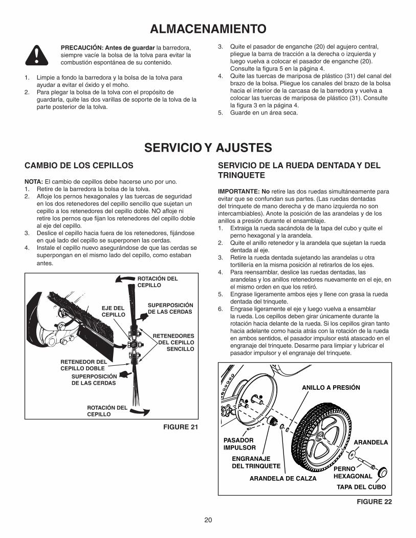
CamBIo De los CePIllos
noTa: El cambio de cepillos debe hacerse uno por uno.Retire de la barredora la bolsa de la tolva.1. Aflojelospernoshexagonalesylastuercasdeseguridad2. en los dos retenedores del cepillo sencillo que sujetan un cepilloalosretenedoresdelcepillodoble.NOaflojeniretirelospernosquefijanlosretenedoresdelcepillodobleal eje del cepillo. Desliceelcepillohaciafueradelosretenedores,fijándose3. en qué lado del cepillo se superponen las cerdas.Instale el cepillo nuevo asegurándose de que las cerdas se 4. superpongan en el mismo lado del cepillo, como estaban antes.
serVICIo Y aJusTesserVICIo De la rueDa DenTaDa Y Del TrInQueTe
ImPorTanTe: no retire las dos ruedas simultáneamente para evitar que se confundan sus partes. (Las ruedas dentadas deltrinquetedemanoderechaydemanoizquierdanosonintercambiables). Anote la posición de las arandelas y de los anillos a presión durante el ensamblaje.
Extraiga la rueda sacándola de la tapa del cubo y quite el 1. perno hexagonal y la arandela. Quite el anillo retenedor y la arandela que sujetan la rueda 2. dentada al eje.Retire la rueda dentada sujetando las arandelas u otra 3. tortillería en la misma posición al retirarlos de los ejes.Para reensamblar, deslice las ruedas dentadas, las 4. arandelas y los anillos retenedores nuevamente en el eje, en el mismo orden en que los retiró.Engrase ligeramente ambos ejes y llene con grasa la rueda 5. dentada del trinquete.Engrase ligeramente el eje y luego vuelva a ensamblar 6. la rueda. Los cepillos deben girar únicamente durante la rotación hacia delante de la rueda. Si los cepillos giran tanto hacia adelante como hacia atrás con la rotación de la rueda en ambos sentidos, el pasador impulsor está atascado en el engranaje del trinquete. Desarme para limpiar y lubricar el pasador impulsor y el engranaje del trinquete.
almaCenamIenTo
Limpie a fondo la barredora y la bolsa de la tolva para 1. ayudar a evitar el óxido y el moho.Para plegar la bolsa de la tolva con el propósito de 2. guardarla, quite las dos varillas de soporte de la tolva de la parte posterior de la tolva.
PreCauCIÓn: antes de guardar la barredora, siempre vacíe la bolsa de la tolva para evitar la combustión espontánea de su contenido.
Quite el pasador de enganche (20) del agujero central, 3. plieguelabarradetracciónaladerechaoizquierdayluego vuelva a colocar el pasador de enganche (20). Consultelafigura5enlapágina4.Quite las tuercas de mariposa de plástico (31) del canal del 4. brazodelabolsa.Pliegueloscanalesdelbrazodelabolsahacia el interior de la carcasa de la barredora y vuelva a colocar las tuercas de mariposa de plástico (31). Consulte lafigura3enlapágina4.Guarde en un área seca.5.
PERNO HEXAGONAL
ARANDELA
TAPA DEL CUBOARANDELA DE CALZA
ANILLO A PRESIÓN
PASADOR IMPULSOR
ENGRANAJE DEL TRINQUETE
ROTACIÓN DEL CEPILLO
ROTACIÓN DEL CEPILLO
SUPERPOSICIÓN DE LAS CERDAS
SUPERPOSICIÓN DE LAS CERDAS
RETENEDORESDEL CEPILLO
SENCILLO
RETENEDOR DEL CEPILLO DOBLE
EJE DELCEPILLO
FIGure 21
FIGure 22

21

22
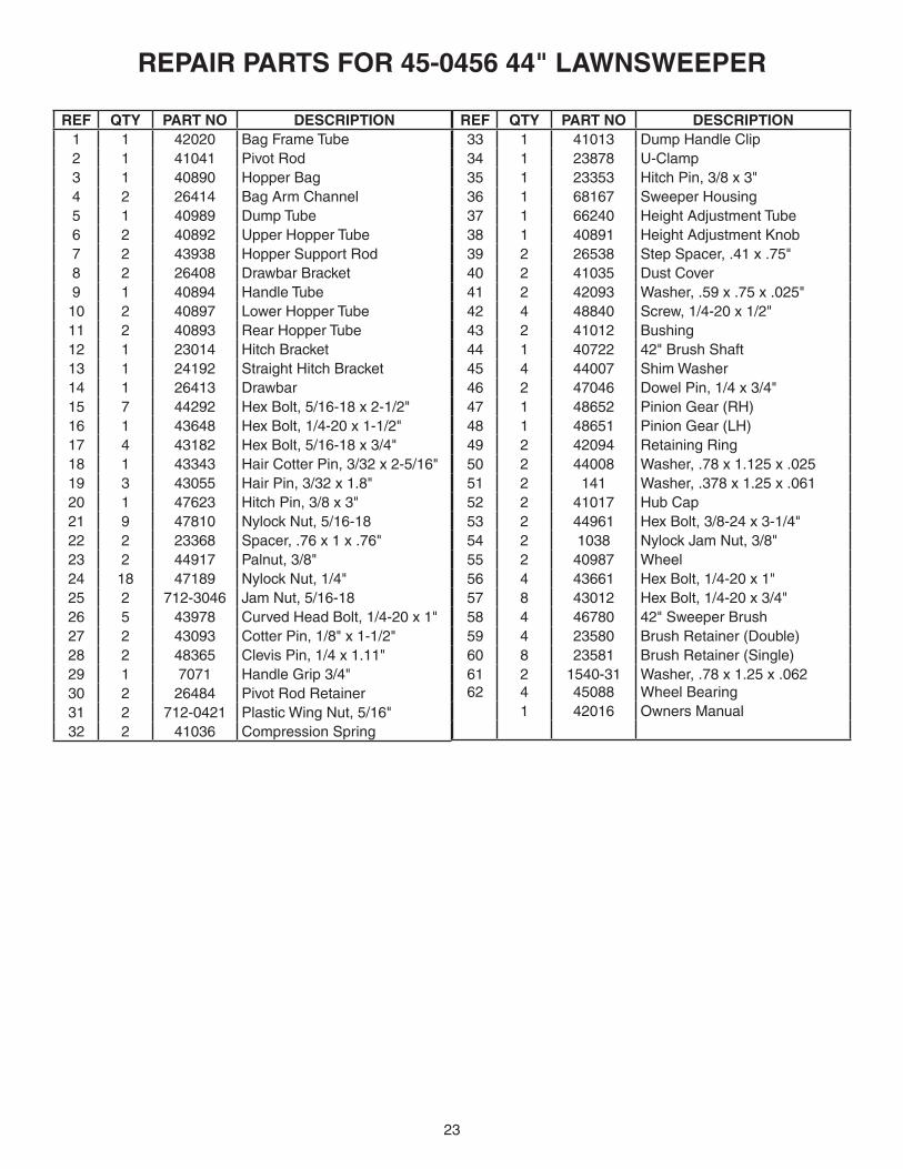
rePaIr ParTs For 45-0456 44" lawnsweePer
5253 55
15
21 15
29
9
24
4
10
28
2825
25
17
17
10
4
5
33
24
1634
7
3032
3032
11
3
27
1
17
26
26
26
26
11
223
23
24
24
24
24
7
26
21
19
17
1921
24
6059
583156
57
6
6
31
36
4250
4941
51
52
4054 39
53
51
4745
43
43
8
8
37
40
2119
2015
15
14
2118
22
12
3515
13
15
46
3844
21
21
4250
61
4941
4845
5439
55
61
62
62
62
62
23
rePaIr ParTs For 45-0456 44" lawnsweePer
reF QTY ParT no DesCrIPTIon 1 1 42020 Bag Frame Tube 2 1 41041 Pivot Rod 3 1 40890 Hopper Bag 4 2 26414 Bag Arm Channel 5 1 40989 Dump Tube 6 2 40892 Upper Hopper Tube 7 2 43938 Hopper Support Rod 8 2 26408 Drawbar Bracket 9 1 40894 Handle Tube 10 2 40897 Lower Hopper Tube 11 2 40893 Rear Hopper Tube 12 1 23014 Hitch Bracket 13 1 24192 Straight Hitch Bracket 14 1 26413 Drawbar 15 7 44292 Hex Bolt, 5/16-18 x 2-1/2" 16 1 43648 Hex Bolt, 1/4-20 x 1-1/2" 17 4 43182 Hex Bolt, 5/16-18 x 3/4" 18 1 43343 Hair Cotter Pin, 3/32 x 2-5/16" 19 3 43055 Hair Pin, 3/32 x 1.8" 20 1 47623 Hitch Pin, 3/8 x 3" 21 9 47810 Nylock Nut, 5/16-18 22 2 23368 Spacer, .76 x 1 x .76" 23 2 44917 Palnut, 3/8" 24 18 47189 Nylock Nut, 1/4" 25 2 712-3046 Jam Nut, 5/16-18 26 5 43978 Curved Head Bolt, 1/4-20 x 1" 27 2 43093 Cotter Pin, 1/8" x 1-1/2" 28 2 48365 Clevis Pin, 1/4 x 1.11" 29 1 7071 Handle Grip 3/4" 30 2 26484 Pivot Rod Retainer 31 2 712-0421 Plastic Wing Nut, 5/16" 32 2 41036 Compression Spring
reF QTY ParT no DesCrIPTIon 33 1 41013 Dump Handle Clip 34 1 23878 U-Clamp 35 1 23353 Hitch Pin, 3/8 x 3" 36 1 68167 Sweeper Housing 37 1 66240 Height Adjustment Tube 38 1 40891 Height Adjustment Knob 39 2 26538 Step Spacer, .41 x .75" 40 2 41035 Dust Cover 41 2 42093 Washer, .59 x .75 x .025" 42 4 48840 Screw, 1/4-20 x 1/2" 43 2 41012 Bushing 44 1 40722 42" Brush Shaft 45 4 44007 Shim Washer 46 2 47046 Dowel Pin, 1/4 x 3/4" 47 1 48652 Pinion Gear (RH) 48 1 48651 Pinion Gear (LH) 49 2 42094 Retaining Ring 50 2 44008 Washer, .78 x 1.125 x .025 51 2 141 Washer, .378 x 1.25 x .061 52 2 41017 Hub Cap 53 2 44961 Hex Bolt, 3/8-24 x 3-1/4" 54 2 1038 Nylock Jam Nut, 3/8" 55 2 40987 Wheel 56 4 43661 Hex Bolt, 1/4-20 x 1" 57 8 43012 Hex Bolt, 1/4-20 x 3/4" 58 4 46780 42" Sweeper Brush 59 4 23580 Brush Retainer (Double) 60 8 23581 Brush Retainer (Single) 61 62
24
1540-3145088
Washer, .78 x 1.25 x .062Wheel Bearing
1 42016 Owners Manual

the fastest way to purchase parts www.speedepart.com
© 2010 Agri-Fab, Inc.
rePaIr ParTsAgri-Fab, Inc.
809 South HamiltonSullivan, IL. 61951
217-728-8388www.agri-fab.com
This document (or manual) is protected under the U.S. Copyright Laws and the copyright laws of foreign countries, pursuant to the Universal Copyright Convention and the Berne convention. No part of this document may be reproduced or transmitted in any form or by any means, electronic or mechanical, including photocopying or recording, or by any informationstorageorretrievalsystem,withouttheexpresswrittenpermissionofAgri-Fab,Inc.Unauthorizedusesand/orreproductionsofthismanualwillsubjectsuchunauthorizedusertocivilandcriminalpenaltiesasprovidedbytheUnitedStates Copyright Laws.