model number structure - alliedelec.com€¦ · 148 general-purpose basic switch z model number...
TRANSCRIPT

General-purpose Basic Switch Z 147
General-purpose Basic Switch
ZBest-selling Basic Switch Boasting High Precision and Wide Variety
• A large switching capacity of 15 A with high repeat accuracy.• A wide range of variations in contact form for your selection:
basic, split-contact and maintained-contact.
• A series of standard models for micro loads is available.• A series of molded terminal-type models incorporating
safety terminal protective cover is available.
Model Number Structure
Available types
• A variety of actuators is available for a wide range of application.• The contact mechanism of models for micro loads is a crossbar
type with gold-alloy contacts, which ensures highly reliable operations for micro loads.
• Contact Gap:H2: 0.20 mm (extra-high-sensitivity)H: 0.25 mm (high-sensitivity, micro voltage current load)G: 0.5 mm (standard)E: 1.8 mm (high-capacity)F: 1.0 mm (split-contact models)
• These Switches use a rubber boot on the actuator and adhesive fillbetween the case and cover to increase resistance to drips.
• Models with drip-proof terminal protective covers and molded terminals with resin filling are also available.
• This type is identical in construction to the general-purpose basicswitch except that it has two pairs of simultaneous acting contactsby splitting moving contacts.
• Since the moving contacts are connected to a common terminal,either parallel or series connection is possible.
• Highly reliable micro load switching is ensured if the model is usedas a twin-contact switch.
• The maintained-contact type has a reset button at the bottom of theswitch case, in addition to the pushbutton (plunger) located on theopposite side of the reset button. Use these buttons alternately.
• Since the Switch has greater pretravel than overtravel, it is suitablefor use in reversible control circuits, manual reset circuits, safetylimit circuits, and other circuits which are not preferable for automatic resetting. (For further details, refer to individualdatasheets.)
Basic models
Split-contact models
Maintained-contact models
General-purpose
Without terminal protective cover
With terminal protective cover
Molded terminal
General-purpose
Drip-proof
General-purpose
General-purpose
Drip-proof
Basic Models Split-contact Models
Maintained-contact Models

148 General-purpose Basic Switch Z
■ Model Number LegendBasic Models
Split-contact Models
Maintained-contact models
Drip-proof with Molded Terminal Models
Z - - 3 4 521
1. Ratings 01: 0.1 A (micro load) 15: 15 A
2. Contact Gap H2: 0.20 mm (extra-high sensitivity) H: 0.25 mm (high-sensitivity, micro load) G: 0.5 mm E: 1.8 mm (high-capacity)
3. Actuator None: Pin plunger S: Slim spring plunger D: Short spring plunger K: Spring plunger (medium OP) K3: Spring plunger (high OP) Q3: Panel mount plunger (low OP) Q: Panel mount plunger (medium OP) Q8: Panel mount plunger (high OP) Q22: Panel mount roller plunger Q21: Panel mount cross roller plunger L: Leaf spring (high OF) L2: Roller leaf spring W21: Short hinge lever W: Hinge lever (low OF) W3: Hinge lever (medium OF) W32: Hinge lever (high OF) W4: Low-force hinge lever
W44: Long hinge lever W78: Low-force wire hinge lever (low OF) W52: Low-force wire hinge lever (high OF) W22: Short hinge roller lever W2: Hinge roller lever W25: Hinge roller lever (large roller) W49: Short hinge cross roller lever W54: Hinge cross roller lever W2277: Unidirectional short hinge roller lever (low OF) M: Reverse hinge lever M22: Reverse short hinge roller lever M2: Reverse hinge roller lever NJ: Flexible rod (high OF) NJS: Flexible rod (low OF)
4. Degree of Protection None: General-purpose 55: Drip-proof A55: Drip-proof (including terminals)
5. Terminals None: Solder terminal B: Screw terminal (with toothed washer) B5V: Screw terminal with terminal cover (for Z-15G@A55 only)
Z - 10 F Y - B 3 4 521
1. Ratings 10: 10 A (split-contact models)
2. Contact Gap F: 1 mm (high-capacity)
3. Actuator None: Pin plunger S: Slim spring plunger D: Short spring plunger Q: Panel mount plunger Q22: Panel mount roller plunger W: Hinge lever W22: Short hinge roller lever W2: Hinge roller lever M22: Reverse short hinge roller lever
4. Construction Y: Split-contact type
5. Terminals None: Solder terminal B: Screw terminal (with toothed washer)
Z - 15 E R3 421
1. Ratings 15: 15 A
2. Contact Gap E: 1.8 mm (high-capacity)
3. Actuator None: Pin plunger S: Slim spring plunger W: Hinge lever
4. Construction R: Maintained-contact models
Z - 55 - M M2 3 41
1. Drip-proof model (Insert model number of basic, drip-proof version with solder terminals)
2. Lead Outlets None: VSF E: VCT
3. Direction of Lead Outlets L: Left R: Right D: Descending
4. Length of Leads 1: 1 m 3: 3 m
L type D type R type

General-purpose Basic Switch Z 149
Ordering InformationBasic Models (General-purpose)
Actuator
Classification Standard High-sensitivity Extra-highsensitivity High-capacity Micro load
Contact gap G (0.5 mm) H (0.25 mm) H2 (0.20 mm) E (1.8 mm) H (0.25 mm)
Terminal *1 Model Model Model Model Model
Pin plungerZ-15G Z-15H Z-15H2 Z-15E Z-01H
Z-15G-B Z-15H-B Z-15H2-B Z-15E-B Z-01H-B
Slim spring plungerZ-15GS Z-15HS
--- ---Z-01HS
Z-15GS-B Z-15HS-B Z-01HS-B
Short spring plunger
Z-15GD Z-15HD---
Z-15ED Z-01HD
Z-15GD-B Z-15HD-B Z-15ED-B Z-01HD-B
Panel mountplunger
Low OPZ-15GQ3
---
---
--- ---Z-15GQ3-B
Medium OP
Z-15GQ Z-15HQ Z-15EQ Z-01HQ
Z-15GQ-B Z-15HQ-B Z-15EQ-B Z-01HQ-B
High OPZ-15GQ8
--- --- ---Z-15GQ8-B
Panel mount roller plunger
Z-15GQ22 Z-15HQ22---
Z-15EQ22---
Z-15GQ22-B Z-15HQ22-B Z-15EQ22-B
Panel mount cross roller plunger
Z-15GQ21 Z-15HQ21---
Z-15EQ21---
Z-15GQ21-B Z-15HQ21-B Z-15EQ21-B
Leaf springZ-15GL
--- --- --- ---Z-15GL-B
Roller leaf springZ-15GL2
--- --- --- ---Z-15GL2-B
Short hinge leverZ-15GW21
--- --- --- ---Z-15GW21-B
Hinge lever
Low OPZ-15GW Z-15HW
--- --- ---
Z-15GW-B Z-15HW-B
Medium OP
Z-15GW3
---Z-15GW3-B
High OPZ-15GW32
Z-15GW32-B
Low-force hinge lever
Z-15GW4 Z-15HW24--- --- ---
Z-15GW4-B Z-15HW24-B
Low- force wire hinge lever
Low OP
---
Z-15HW78
--- --- ---Z-15HW78-B
High OPZ-15HW52
Z-15HW52-B
Short hinge roller lever
Z-15GW22 Z-15HW22---
Z-15EW22 Z-01HW22
Z-15GW22-B Z-15HW22-B Z-15EW22-B Z-01HW22-B
Short hinge cross roller lever
Z-15GW49--- --- --- ---
Z-15GW49-B
Hinge roller lever
StandardZ-15GW2 Z-15HW2
---
--- ---Z-15GW2-B Z-15HW2-B
Large rollerZ-15GW25
--- --- ---Z-15GW25-B

150 General-purpose Basic Switch Z
*1. : Solder terminal : Screw terminal*2. The pin plungers of reverse-type models are continuously pressed by the actuator levers with compression coil springs and the pin plungers
are freed by operating the levers. Reverse-type models are highly vibration- and shock-resistive because the pin plungers are normally pressed.
Split-contact Models Maintained-contact Models
*1. : Solder terminal : Screw terminal*2. The pin plungers of reverse-type models are continuously pressed by the actuator levers with compression coil springs and the pin plungers
are freed by operating the levers. Reverse-type models are highly vibration- and shock-resistive because the pin plungers are normally pressed.
Hinge cross roller lever
Z-15GW54--- --- --- ---
Z-15GW54-B
Unidirectional short hinge roller lever
ParallelZ-15GW2277
--- --- --- ---Z-15GW2277-B
Reverse hinge lever *2
Z-15GM--- --- --- ---
Z-15GM-B
Reverse short hinge roller lever *2
Z-15GM22--- --- --- ---
Z-15GM22-B
Reverse hinge roller lever *2
Z-15GM2--- --- --- ---
Z-15GM2-B
Actuator
Classification Standard High-sensitivity Extra-highsensitivity High-capacity Micro load
Contact gap G (0.5 mm) H (0.25 mm) H2 (0.20 mm) E (1.8 mm) H (0.25 mm)
Terminal *1 Model Model Model Model Model
Contact gap F (1.0 mm)
Actuator Terminal *1 Model
Pin plunger---
Z-10FY-B
Slim spring plunger---
Z-10FSY-B
Short spring plunger---
Z-10FDY-B
Panel mount plunger
---
Z-10FQY-B
Panel mount roller plunger
---
Z-10FQ22Y-B
Hinge lever---
Z-10FWY-B
Short hinge roller lever
---
Z-10FW22Y-B
Hinge roller lever---
Z-10FW2Y-B
Reverse short hinge roller lever *2
---
Z-10FM22Y-B
Actuator Model
Pin plunger Z-15ER
Slim spring plunger Z-15ESR
Hinge lever Z-15EWR

General-purpose Basic Switch Z 151
Drip-proof Models
*1. : Solder terminal : Screw terminal*2. The pin plungers of reverse-type models are continuously pressed by the actuator levers with compression coil springs and the pin plungers
are freed by operating the levers.*3. The tip is made of resin.
Actuator
Classification Standard High-sensitivity Micro load
Contact gap G (0.5 mm) H (0.25 mm) H (0.25 mm)
Drip-proof terminalprotective cover Not provided Provided Not provided Not provided
Terminal *1 Model Model Model Model
Pin plungerZ-15G55 --- Z-01H55
Z-15G55-B Z-15GA55-B5V Z-01H55-B
Short spring plungerZ-15GD55
---Z-01HD55
Z-15GD55-B Z-01HD55-B
Spring plunger
Low OP
Z-15GK55--- ---
Z-15GK55-B
High OP
Z-15GK355 ------
Z-15GK355-B Z-15GK3A55-B5V
Panel mount plungerZ-15GQ55 ---
---Z-15GQ55-B Z-15GQA55-B5V
Panel mount roller plunger
Z-15GQ2255 ------
Z-15GQ2255-B Z-15GQ22A55-B5V
Panel mount cross roller plunger
--- ------
Z-15GQ2155-B Z-15GQ21A55-B5V
Leaf springZ-15GL55
--- ---Z-15GL55-B
Roller leaf springZ-15GL255
--- ---Z-15GL255-B
Short hinge leverZ-15GW2155
--- ---Z-15GW2155-B
Long hinge leverZ-15GW4455 ---
---Z-15GW4455-B Z-15GW44A55-B5V
Hinge leverZ-15GW55 ---
---Z-15GW55-B Z-15GWA55-B5V
Short hinge roller leverZ-15GW2255 --- Z-01HW2255
Z-15GW2255-B Z-15GW22A55-B5V Z-01HW2255-B
Hinge roller leverZ-15GW255 ---
---Z-15GW255-B Z-15GW2A55-B5V
Unidirectional short hinge roller lever
Z-15GW227755 ------
Z-15GW227755-BZ-15GW2277A55-
B5V
Reverse hinge lever *2Z-15GM55
--- ---Z-15GM55-B
Reverse short hinge roller lever *2
Z-15GM2255--- ---
Z-15GM2255-B
Reverse hinge roller lever *2
Z-15GM255--- ---
Z-15GM255-B
Flexible rod (coil spring) *3Z-15GNJ55
--- ---Z-15GNJ55-B
Flexible rod(steel wire) --- ---
Z-15HNJS55---
Z-15HNJS55-B

152 General-purpose Basic Switch Z
Specifications■ Characteristics
*1 The values are for the plunger models. (For the lever models, the values are at the plunger section.)*2 The values are for the Z-15G pin plunger.*3 The values are for the Z-10FY-B.
*4 The values are for the pin plunger. The service life for models other than the pin plunger is 10,000,000 min.*5 Malfunction: 1 ms max.
■ Ratings (Basic, Split-contact and Maintained contact Models)Z-15 (Except Micro Load and Flexible Rod Models)
* Figures in parentheses are for the Z-15HW52, Z-15HW78(-B) and Z-15H2(-B) models, the AC ratings of these models are 125 and 250 V only.
ItemClassification
Z-15 (except micro load and flexible rod)
Z-01H Z-15 (flexible rod) Z-10F Z-15H2
Operating speed 0.01 mm to 1 m/s (*1) 1 mm to 1 m/s 0.1 mm to 1 m/s (*1) 0.01 mm to 1 m/s
Operating frequency
Mechanical 240 operations/min 120 operations/min 240 operations/min 240 operations/min
Electrical 20 operations/min
Contact resistance 15 mΩ max. (initial value) 50 mΩ max. (initial value) 15 mΩ max. (initial value) 25 mΩ max. (initial value) 15 mΩ max. (initial value)Insulation resistance 100 MΩ min. (at 500 VDC)
Dielectric strength(50 / 60 Hz for 1 min.)
Between contacts of same polarityContact gap G: 1,000 VACContact gap H: 600 VACContact gap E: 1,500 VAC
Between contacts of same polarityContact gap G: 1,000 VACContact gap H: 600 VAC
Between contacts of same polarityContact gap F: 1,500 VAC
Between contacts of same polarity600VAC
Between current-carrying metal parts and ground, and between each terminal and non-current-carrying metal parts: 2,000 VAC
Vibration resistance
Malfunction10 to 55 Hz, 1.5-mm double amplitude (*5) 10 to 20 Hz, 1.5-mm double amplitude (*5) 10 to 55 Hz, 1.5-mm double amplitude (*5)
Shock resistance
Destruction 1,000 m/s2 max.
Malfunction 300 m/s2 max. (*2, *5) 50 m/s2 max. (*5) 300 m/s2 max. (*3, *5) 100 m/s2 max.
Degree of protection
General-purpose
IP00
Drip-proof Equivalent to IP62 (except terminals)
Degree of protection against electric shock
Class I
Proof tracking index(PTI)
175
Ambient operating temperature
General-purpose
−25°C to 80°C (with no icing)
Drip-proof −15°C to 80°C (with no icing)
Ambient operating humidity
General-purpose
35% to 85%RH
Drip-proof 35% to 95%RH
Service lifeMechanical
Contact gap H2: 10,000,000 operations min. Contact gap G, H: 20,000,000 operations min.(*4)Contact gap E: 300,000 operations
1,000,000 operations min. 500,000 operations min. (*1) 20,000,000 operations min.
Electrical Contact gap G, H: 500,000 operations min.Contact gap E: 100,000 operations min.
100,000 operations min. 100,000 operations min. 500,000 operations min.
Weight Approx. 22 to 58 g Approx. 42 to 48 g Approx. 34 to 61 g Approx. 22 g
Item Non-inductive load (A) Inductive load (A)Resistive load Lamp load Inductive load Motor load
Contact gap Rated voltage NC NO NC NO NC NO NC NO
G, H, H2, E125 VAC250 VAC500 VAC *
15 (10) *15 (10) *
10
32.51.5
1.51.250.75
15 (10) *15 (10) *
6
53
1.5
2.51.50.75
G
8 VDC14 VDC30 VDC125 VDC250 VDC
15156
0.50.25
333
0.50.25
1.51.51.50.5
0.25
15105
0.050.03
555
0.050.03
2.52.52.50.050.03
H, H2
8 VDC14 VDC30 VDC125 VDC250 VDC
15152
0.40.2
332
0.40.2
1.51.51.40.40.2
15101
0.030.02
551
0.030.02
2.52.51
0.030.02
E
8 VDC14 VDC30 VDC125 VDC250 VDC
151515
0.750.3
333
0.750.3
1.51.51.5
0.750.3
1515100.40.2
555
0.40.2
2.52.52.50.40.2

General-purpose Basic Switch Z 153
Z-15 (Flexible Rod Models)
Z-10F
Z-01H
Applicable Load Range
■ Contacts Specification
■ Safety Standards RatingsUL/CSA (General ratings only)
TÜV (EN61058-1)
Note: 1. The above current ratings are the values of the steady-state current.2. Inductive load has a power factor of 0.4 min. (AC) and a time
constant of 7 ms max. (DC).3. Lamp load has an inrush current of 10 times the steady-state current.4. Motor load has an inrush current of 6 times the steady-state current.5. The normally closed and normally open ratings of reverse hinge
lever models are opposite to each other.
6. The AC ratings of molded terminals are 125 and 250 V only.7. The ratings values apply under the following test conditions:
(1) Ambient temperature: 20±2°C(2) Ambient humidity: 65±5%RH(3) Operating frequency: 20 operations/min
8. Consult Omron regarding CCC standards and ratings.
Rated voltage
Non-inductive load (A) Inductive load (A)
Resistive load Lamp load Inductive load Motor load
NC NO NC NO NC NO NC NO
125 VAC250 VAC
1515
21
10.5
75
2.51.5
21
8 VDC14 VDC30 VDC125 VDC250 VDC
15152
0.40.2
222
0.40.2
111
0.40.2
771
0.030.02
331
0.030.02
1.51.50.5
0.030.02
Item Non-inductive load (A) Inductive load (A)
Resistive load Lamp load Inductive load Motor load
Contact gap Rated voltage NC NO NC NO NC NO NC NO
Series connection
125 VAC250 VAC
1010
42.5
21.5
66
53
2.51.5
30 VDC125 VDC250 VDC
101
0.6
41
0.6
21
0.6
60.1
0.05
60.1
0.05
30.1
0.05
Parallel connection
125 VAC250 VAC
66
32.5
1.51.25
44
42
21
30 VDC125 VDC250 VDC
60.60.3
40.60.3
20.60.3
40.1
0.05
60.1
0.05
30.1
0.05
Rated voltageResistive load (A)
NC NO
125 VAC 0.1
8 VDC14 VDC30 VDC
0.10.10.1
Z-01H Z-15@, Z-10FY
Minimum applicable load 1 mA at 5 VDC 160 mA at 5 VDC
30
24
12
5
01 10 100 1,000
Current (mA)
0.1
1 mA
Standard loadareaZ-15H, H2Z-15GZ-15EZ-10FYZ-15ER
Micro load area Z-01H
26 mA0.16 mA
800 mW5 mW
100 mA 160 mA
Unusablerange
Vol
tage
(V
)
Item Classification Z-15 Z-01H Z-10F
ContactsShape Rivet Single
crossbar Rivet
Material Silver Gold alloy Silver
Inrush currentNC 30 A max. 0.1 A max. 40 A max.
NO 15 A max. 0.1 A max. 20 A max.
Rated voltage Model Z-15 Z-10F Z-01H
125 VAC 15A and 1/8HP 6A and 1/10HP 0.1A
250 VAC 15A and 1/4HP 6A and 1/8HP ---
480 VAC 15A 6A ---
30 VDC --- --- 0.1A
125 VDC 0.5A 0.6A ---
250 VDC 0.25A 0.3A ---
Rated voltage Model Z-15H@-B Z-15G@-B Z-01H@-B
250 VAC 15 A 15 A ---
125 VAC --- --- 0.1 A
30 VDC --- --- 0.1 A

154 General-purpose Basic Switch Z
Engineering Data
■ Mechanical Durability (Z-15G) ■ Electrical Durability (Z-15G)
■ StructureBasic ModelsContact Form (SPDT)
Note: The Z-15GM is a reversible model and the NO and NC positions are reversed.
Molded Terminals
Note: The Z-15GM is a reversible model and the NO and NC positions are reversed.
Drip-proof ConstructionWithout Terminal Protective Cover With Terminal Protective Cover
Split-Contact ModelsContact Form
Note: The NO and NC terminal arrangement is reversed for Models with reverse operation (Z-10FM).
Connection Example
Maintained-contact ModelsContact Form
500
1,000
300
100
5,000
10,000
3,000
0.20.1 0.4 0.6 0.80.3 0.5 0.7
Overtravel (mm)
0
Ambient temperature: 20±2°CAmbient humidity: 65±5%RHWithout loadOperating frequency: 240 operations/min
Dur
abili
ty (
x104 o
pera
tions
)
50
100
30
10
500
1,000
300
5,000
3,000
42 8 12 166 10 14
Switching Current (A)
0
Ambient temperature: 20±2°CAmbient humidity: 65±5%RHOperating frequency: 20 operations/min.
125 VAC cos dia. = 1125 VAC cos dia. = 0.4
250 VAC cos dia. = 1250 VACcos dia. = 0.4
500 VAC cos dia. = 0.4
500 VAC cos dia. = 1
Dur
abili
ty (
x104 o
pera
tions
)
COM NC
NO
COM (Black) (Red) NC
(White) NO
( ) indicates wire color.
Rubber boot Fixed contact (b)Movable spring Glued surface
(adhesive isfilled betweencase and cover)
Movable contact
Fixed contact (a)Spring pivot
Rubber boot (weather-resistivechloroprene is used)
Stainless-steel stopper(improves sealing)
Rubber packing (improvessealing between switchhousing and terminal cover)
Terminal protective covers are sold separatelyfor maintenance purposes, which can be, how-ever, used with the Z-@-B5V models only.
NC
NOCOM
NC
NO
Series Connection Parallel Connection
Pushbutton for resetting
COM NC
NO

General-purpose Basic Switch Z 155
Dimensions■ General-purpose and Split Contact ModelsNote: Unless otherwise specified, all units are in millimeters and a tolerance of ± 0.4 mm applies to all dimensions
Terminals
MountingAll switches can be side mounted using M4 mounting screws withplane washers or spring washers to securely mount the Switch.Tighten the screws to a torque of 1.18 to 1.47 N·m.
Versions with panel mount plungers can be panel mounted via theplunger, provided that the hexagonal nut of the actuator is tightenedto a torque of 2.94 to 4.9 N·m.
Note: Mount using either the side mounting holes or the panel mountplunger, not both. If using the side mounting holes, then removethe hexagonal nut(s) from the panel mount plunger.
General-purpose Models Split-contact Models
Note: With reverse action models (Z-15GM), the positions of NO and NC terminals are reversed.
COM NO NC
1 3 2
49.2
17.45±0.2
Three, M4 × 5.5Terminal screws(with toothedwasher)
9.2
20 20
Screw Terminals (-B)
Appropriate terminal screw tightening torque: 0.78 to 1.18 N·m.
COMNO
NC
1
2
3
11.925.4±0.1
6.4
49.2
17.45±0.2
Solder Terminal (Blank)
CO
M NO
NC
NO
NC
17.45±0.2
Five, M3.5 × 5.5terminal screws(with toothedwasher)
5.6
23 17.1
11.9
Screw Terminals (Y-B)
Appropriate terminal screw tightening torque: 0.49 to 0.78 N·m.
Note: With reverse action models (Z-10FM),the positions of NO and NC terminalsare reversed.
25.4±0.1
Two, 4.2 dia. mounting holes or M4
12.5 dia.+0.20
12.5 dia.+0.20
13+0.20
5+0.20
Panel Mount Roller PlungerPanel Mount Plunger
Accessories (Terminal Covers, Actuators, and Separators): Refer to ‘Z/A/X/DZ Common Accessories’ datasheet

156 General-purpose Basic Switch Z
Note: 1. All drawings show the switches with screw terminals. For versions with solder terminals, remove the “-B” from the end of the part number.2. Unless otherwise specified, all units are in millimeters and a tolerance of ± 0.4 mm applies to all dimensions.
49.2
11.925.4±0.1
23.3±0.25
24.2
17.45±0.2
OP
PT2.3 dia.
2.3SR *
* Stainless-steel plunger
9.2
4.36 dia.+0.1 -0.05
4.2+0.075-0.025
4.2 dia. hole+0.075 -0.025
Pin PlungerZ-15G-B Z-15E-BZ-15H2-B Z-01H-BZ-15H-B Z-10FY-B
Operating Characteristics Z-15G-B Z-15H2-B Z-15H-B Z-15E-B Z-01H-B Z-10FY-B
Operating force Release forcePretravel Overtravel Movement Differential
OFRF min.PT max.OT min.MD max.
250 to 350 gf114 gf0.4 mm0.13 mm0.05 mm
200 to 255 gf114 gf0.3 mm0.13 mm
0.005 to 0.008 mm
200 to 280 gf114 gf0.3 mm0.13 mm
0.025 mm
625 to 800 gf114 gf0.8 mm
0.13 mm0.13 mm
250 gf max.80 gf
0.5 mm0.13 mm0.04 mm
455 to 740 gf114 gf0.8 mm0.13 mm0.1 mm
Operating Position OP 15.9±0.4 mm
49.2
11.925.4±0.1
23.3±0.25
24.2
17.45±0.2
OP
PT5.2 dia.
* Stainless-steel plunger (flat, 1R chamfered)
*4 dia.
9 dia.
9.2
4.36 dia.+0.1 -0.05
4.2+0.075-0.025
4.2 dia. hole+0.075 -0.025
Model Z-15GS-B Z-15HS-B Z-01HS Z-10FSY-B
OFRF min.PT max.OT min.MD max.
250 to 350 gf114 gf
0.4 mm1.6 mm0.05 mm
200 to 285 gf114 gf
0.3 mm1.6 mm
0.025 mm
250 gf max.80 gf
0.5 mm1.6 mm0.05 mm
455 to 740 gf114 gf
0.8 mm1.6 mm0.1 mm
OP 28.2±0.5 mm
Slim Spring PlungerZ-15GS-B Z-01HS-BZ-15HS-B Z-10FSY-B
49.2
11.925.4±0.1
23.3±0.25
24.2
17.45±0.2
OP
PT10 dia.
12.3 dia.
12SR *
* Plated iron plunger
7.15 dia.
9.2
4.36 dia.+0.1 -0.05
4.2+0.075-0.025
4.2 dia. hole+0.075 -0.025
Short Spring PlungerZ-15GD-B Z-01HD-BZ-15HD-B Z-10FDY-BZ-15ED-B
Model Z-15GD-B Z-15HD-B Z-15ED-B Z-01HD-B Z-10FDY-B
OFRF min.PT max.OT min.MD max.
250 to 350 gf114 gf0.4 mm1.6 mm0.05 mm
200 to 285 gf114 gf0.3 mm1.6 mm
0.025 mm
625 to 800 gf114 gf0.8 mm1.6 mm0.13 mm
250 gf max.80 gf
0.5 mm1.6 mm0.05 mm
455 to 740 gf114 gf0.8 mm1.6 mm0.1 mm
OP 21.5±0.5 mm

General-purpose Basic Switch Z 157
Note: 1. All drawings show the switches with screw terminals. For versions with solder terminals, remove the “-B” from the end of the part number.2. Unless otherwise specified, all units are in millimeters and a tolerance of ± 0.4 mm applies to all dimensions.
49.2
11.925.4±0.1
23.3±0.25
17.45±0.2
OP
PT8.35 dia.
11.9SR *1
*1. Stainless-steel plunger*2. Two hexagonal nuts (2 t × 14 width across flats)*3. Two lock nuts (2 t × 15.6 width across flats)*4. Incomplete screw part with a maximum length of 1.5 mm.
*416.3
13.1*2
*3
M12 × 1mounting screw
16 dia.
9.2
4.36 dia.+0.1 -0.05
4.2+0.075-0.025
4.2 dia. hole+0.075 -0.025
Panel Mount PlungerZ-15GQ-B Z-01HQ-BZ-15HQ-B Z-10FQY-BZ-15EQ-B Z-15GQ3-B *Z-15GQ8-B *
* The external dimensions of the actuator vary.
Note: 1. Do not use the M12 mountingscrew and the case mounting holeat the same time, or excessivepulling force will be imposed onthe switch and the case and covermay be damaged.
2. On the model Z-15GQ3-B, PTcan be set to a value larger thanthat for the Z-15GQ.
3. On the model Z-15GQ8-B, operating position can be adjust-ed by providing a screw in theplunger section.
4. On the model Z-15GQ8-B, theM3 hole with a depth of 10 mm isa through hole. Take precautionsso that no water or screw lockagent penetrates into the hole.
Model Z-15GQ-B Z-15HQ-B Z-15EQ-B Z-01HQ-B Z-10FQY-B Z-15GQ3-B Z-15GQ8-BOFRF min.PT max.OT min.MD max.
250 to 350 gf114 gf0.4 mm5.5 mm
0.05 mm
200 to 285 gf114 gf0.3 mm5.5 mm
0.025 mm
625 to 800 gf114 gf0.8 mm5.5 mm
0.13 mm
250 gf max.80 gf
0.5 mm5.5 mm0.05 mm
455 to 740 gf114 gf
0.8 mm5.5 mm0.1 mm
250 to 350 gf114 gf
4.2 mm2.5 mm2.2 mm
250 to 350 gf114 gf
0.5 mm5.5 mm0.05 mm
OP 21.8±0.8 mm 18.8±0.8 mm 32.5±1 mm
49.2
11.925.4±0.1
23.3±0.25
OP
PT
*1. Stainless-steel roller*2. Two hexagonal nuts (3 t × 17 width across flats)*3. Incomplete screw part with a maximum length of 1.5 mm.
17.45±0.2
4.36 dia.+0.1 -0.05
*316.3
15.5
*2
12.7 dia. × 4.8 *1
16 dia.
M12 × 1mountingscrew
9.24.2+0.075
-0.025
4.2 dia. hole+0.075-0.025
Panel Mount Roller PlungerZ-15GQ22-B Z-15EQ22-BZ-15HQ22-B Z-10FQ22Y-B
Model Z-15GQ22-B Z-15HQ22-B Z-15EQ22-B Z-10FQ22Y-BOFRF min.PT max.OT min.MD max.
250 to 350 gf114 gf0.4 mm3.58 mm0.05 mm
200 to 285 gf114 gf0.3 mm
3.58 mm0.025 mm
625 to 800 gf114 gf0.8 mm
3.58 mm0.13 mm
455 to 740 gf114 gf1 mm
3.55 mm0.1 mm
OP 33.4±1.2 mm
Note: Do not use the M12 mounting screwand the case mounting hole at the sametime, or the case may be damaged.
49.2
11.925.4±0.1
23.3±0.25
17.45±0.2
OP
PT
*1. Stainless-steel roller*2. Two hexagonal nuts (3 t × 17 width across flats)*3. Incomplete screw part with a maximum length of 1.5 mm.
4.2+0.075-0.025
4.2 dia. hole+0.075 -0.025
4.36 dia.+0.1 -0.05
*316.3
15.5
*2
12.7 dia. × 4.8 *1
16 dia.
M12 × 1mountingscrew
9.2
Panel Mount Cross Roller PlungerZ-15GQ21-B Z-15EQ21-BZ-15HQ21-B
Model Z-15GQ21-B Z-15HQ21-BOFRF min.PT max.OT min.MD max.
250 to 350 gf114 gf0.4 mm3.58 mm0.05 mm
200 to 285 gf114 gf0.3 mm
3.58 mm0.025 mm
OP 33.4±1.2 mm
Model Z-15EQ21-BOFRF min.PT max.OT min.MD max.
625 to 800 gf114 gf0.8 mm3.58 mm0.13 mm
OP 33.4±1.2 mmNote: Do not use the M12 mounting screw and
the case mounting hole at the same time,or the case may be damaged.

158 General-purpose Basic Switch Z
Note: 1. All drawings show the switches with screw terminals. For versions with solder terminals, remove the “-B” from the end of the part number.2. Unless otherwise specified, all units are in millimeters and a tolerance of ± 0.4 mm applies to all dimensions.
49.2
11.925.4±0.1
49.6±0.8
23.9
17.45±0.2
OPFP
4.8
* Stainless-steel spring lever
4.2+0.075-0.025
4.2 dia. hole+0.075 -0.025
4.36 dia.+0.1 -0.05
t = 0.3*
9.2
Leaf SpringZ-15GL-B
* When operating, be sure not to exceed 1.6 mm.
OF max.RF min.*OT min.MD max.
141 gf14 gf
1.6 mm1.3 mm
FP max.OP
20.6 mm17.4±0.8 mm
4.2+0.075-0.025
4.2 dia. hole+0.075-0.025
4.36 dia.+0.1-0.05
49.2
11.925.4±0.1
46 ±0.8
23.9
17.45±0.2
OPFP
* Stainless-steel spring lever
t = 0.3 *
9.5 dia. × 4(plastic toller)
9.2
Roller Leaf SpringZ-15GL2-B
* When operating, be sure not to exceed 1.6 mm.
OF max.RF min.*OT min.MD max.
141 gf14 gf
1.6 mm1.3 mm
FP max.OP
31.8 mm28.6±0.8 mm
17.45±0.2
4.2+0.075-0.025 4.2 dia. hole+0.075
-0.025
4.36 dia.+0.1-0.05
49.2
11.925.4±0.1
26.2
OP FP
4.9
* Stainless-steel lever
t = 1 *
20.2 16.9 13.9
28.2R
9.2
Short Hinge LeverZ-15GW21-B
OF max.RF min.OT min.MD max.
160 gf28 gf2 mm1 mm
FP max.OP
24.8 mm19±0.8 mm
17.45±0.2
4.2+0.075-0.025 4.2 dia. hole+0.075
-0.025
4.36 dia.+0.1-0.05
49.2
11.925.4±0.1
26.2
OPFP
4.9
* Stainless-steel lever
t = 1 *
20.2 16.9 13.9
63.5R
9.2
Hinge LeverZ-15GW-B Z-15GW32-BZ-15HW-B Z-10FWY-BZ-15GW3-B (Lever Length: 56R)*
Model Z-15GW-B Z-15HW-B Z-15GW32-B Z-10FWY-B Z-15GW3-BOFRF min.OT min.MD max.
70 gf max.14 gf
5.6 mm1.27 mm
67 gf max.14 gf
5.6 mm0.63 mm
150 to 200 gf93 gf
5.6 mm1.27 mm
90 gf max.14 gf
5.6 mm2.4 mm
80 gf max.15 gf
4.8 mm1.12 mm
FP max. 28.2 mm 27.4 mm 28.2 mm 29.8 mm 27.2 mmOP 19±0.8 mm
* The external dimensions of the actuator vary.

General-purpose Basic Switch Z 159
Note: 1. All drawings show the switches with screw terminals. For versions with solder terminals, remove the “-B” from the end of the part number.2. Unless otherwise specified, all units are in millimeters and a tolerance of ± 0.4 mm applies to all dimensions.
49.2
11.925.4±0.1
26.2
OP
PT
4.9
* Stainless-steel lever
t = 1 *
20.2 16.9 13.9
63.5R
9.2
17.45±0.2
4.2+0.075-0.025 4.2 dia. hole+0.075
-0.025
4.36 dia.+0.1-0.05
Low-force Hinge LeverZ-15GW4-B
OF max.RF min.PT max.OT min.MD max.
28 gf3.5 gf10 mm5.6 mm
1.27 mmOP 19±0.8mm
25.4±0.1
* Stainless-steel lever
t = 0.8 *
17.45±0.2
4.2 dia. hole+0.075-0.025
4.36 dia.+0.1-0.05
49.2
11.9
26.2
OP
PT
5
20.2 16.9 13.9
021R 2
9.24.2+0.075
-0.025
120R
Z-15HW24-B
OF max.RF min.PT max.OT min.MD max.
6 gf0.5 gf
19.8 mm10 mm2 mm
OP 19.8±1.6 mm
25.4±0.1* Stainless-steel wire lever
t = 1 *
3 max.
17.45±0.2
4.2+0.075-0.025 4.2 dia. hole+0.075
-0.0254.36 dia.+0.1
-0.05
49.2
11.9
26.2
OP
PT
20.2 16.9 13.9
9.2
63.5R
Low-force Wire Hinge LeverZ-15HW52-BZ-15HW78-B (Lever Length: 110R) *
Model Z-15HW52-BOF max.RF min.PT max.OT min.MD max.
6 gf0.5 gf
8.3 mm5.6 mm
0.65 mmOP 19±1 mm
Model Z-15HW78-BOF max.RF min.PT max.OT min.MD max.
4 gf0.3 gf10 mm6 mm3 mm
OP 20±1 mm
* The external dimensions of the actuator vary.
Note: AC electrical ratings: 10 A, 125/250 V.
49.2
11.925.4±0.1
26.2
OP FP
* Stainless-steel lever
t = 1 *
20.2 16.9 13.9
26.6
R
9.5 dia. × 4(plastic roller)
9.2
17.45±0.2
4.2+0.075-0.025 4.2 dia. hole+0.075
-0.025
4.36 dia.+0.1-0.05
Short Hinge Roller LeverZ-15GW22-B Z-01HW22-BZ-15HW22-B Z-10FW22Y-BZ-15EW22-BZ-15GW2-B * Z-15HW2-B *Z-10FW2Y-B *
* The external dimensions of the actuator vary.(Lever Length: 48.5R)
Model Z-15GW22-B Z-15HW22-B Z-15EW22-B Z-01HW22-B Z-10FW22Y-B Z-15GW2-B Z-15HW2-B Z-10FW2Y-B
OFmax.RF min.OT min.MD max.
160 gf42 gf
2.4 mm0.5 mm
150 gf42 gf
2.4 mm0.45 mm
198 gf42 gf
2.4 mm1.3 mm
160 gf28 gf
2.4 mm0.5 mm
250 gf35 gf
2.4 mm1 mm
100 gf22 gf4 mm
1.02 mm
86 gf22 gf4 mm
0.6 mm
130 gf22 gf4 mm2 mm
FP max.OP
32.5 mm30.2±0.4 mm
35.1 mm30.2±0.4 mm
32.5 mm30.2±0.4 mm
34.8 mm30.2±0.4 mm
36.5 mm30.2±0.8 mm
37.4 mm30.2±0.8 mm

160 General-purpose Basic Switch Z
Note: 1. All drawings show the switches with screw terminals. For versions with solder terminals, remove the “-B” from the end of the part number.2. Unless otherwise specified, all units are in millimeters and a tolerance of ± 0.4 mm applies to all dimensions.
49.2
11.925.4±0.1
26.2
OPFP
9.2
* Stainless-steel lever
t = 1 *
20.2 16.9 13.9
27.1
R
9.5 dia. × 4(plastic roller)
17.45±0.2
4.2+0.075-0.025 4.2 dia. hole+0.075
-0.025
4.36 dia.+0.1-0.05
Short Hinge Cross Roller LeverZ-15GW49-BZ-15GW54-B (Lever Length: 48.7R) * Model Z-15GW49-B Z-15GW54-B
OF max.RF min.OT min.MD max.
170 gf42 gf
2.4 mm0.51 mm
100 gf22 gf4 mm1 mm
FP max.OP
33.3 mm31±0.4 mm
37.3 mm31±0.8 mm* The external dimensions
of the actuator vary.
17.45±0.2
4.2+0.075-0.025 4.2 dia. hole+0.075
-0.025
4.36 dia.+0.1-0.05
49.2
11.925.4±0.1
26.2
OPFP
* Stainless-steel lever
t = 1*
20.2 16.9 13.9
50R
20 dia. × 4(plastic roller)R2
9.2
Hinge Roller LeverZ-15GW25-B
OF max.RF min.OT min.MD max.
100 gf21 gf4 mm
1.6 mmFP max.OP
47.5 mm41.2±0.8 mm
49.2
11.925.4±0.1
26.2
Operating direction
OP FP
* Stainless-steel lever
t = 1 *
20.2
34.1 max.
16.9 13.9
9.5 dia. × 4(plastic roller)
11.1R
31.9
R
9.2
17.45±0.2
4.2+0.075-0.025 4.2 dia. hole+0.075
-0.025
4.36 dia.+0.1-0.05
Unidirectional Short Hinge Roller LeverZ-15GW2277-B
OF max.RF min.OT min.MD max.
170 gf42 gf
2.4 mm0.51 mm
FP max.OP
43.6 mm41.3±0.8 mm
49.2
11.925.4±0.1
18.65 56R4.9
OP FP
* Stainless-steel lever
t = 1 *
20.2 17.4 13.9
9.2
17.45±0.2
4.2+0.075-0.025 4.2 dia. hole+0.075
-0.025
4.36 dia.+0.1-0.05
Reverse Hinge Lever **Z-15GM-B
OF max.RF min.OT min.MD max.
170 gf28 gf
5.6 mm0.89 mm
FP max.OP
23.8 mm19±0.8 mm
49.2
11.925.4±0.1
18.65
OP FP
* Stainless-steel lever
t = 1 *
20.2 17.4 13.9
18.5
R
9.5 dia. × 4(plastic roller)
9.2
17.45±0.2
4.2+0.075-0.025 4.2 dia. hole+0.075
-0.025
4.36 dia.+0.1-0.05
Reverse Short Hinge Roller Lever **Z-15GM22-BZ-10FM22Y-B
Z-15GM22-B Z-10FM22Y-BOF max.RF min.OT min.MD max.
538 gf170 gf2 mm
0.28 mm
650 gf170 gf2 mm
0.56mmFP max.OP
31.8 mm29.4±0.4 mm
33 mm29.4±0.4 mm
17.45±0.2
4.2+0.075-0.025 4.2 dia. hole+0.075
-0.025
4.36 dia.+0.1-0.05
49.2
11.925.4±0.1
18.65
OPFP
* Stainless-steel lever
t = 1*
20.2 17.4 13.9
9.5 dia. × 4(plastic roller)
40.6R
9.2
Reverse Hinge Roller Lever **Z-15GM2-B
**The pin plungers of reverse-type models are continuouslypressed by the actuator levers with compression coil springsand the pin plungers are freed by operating the levers.Reverse-type models are highly vibration- and shock-resis-tive because the pin plungers are normally pressed.
OF max.RF min.OT min.MD max.
240 gf56 gf4 mm
0.64 mmFP max.OP
35 mm30.2±0.8 mm

General-purpose Basic Switch Z 161
■ Drip-proof Models (without Terminal Protective Cover)Note: 1. All drawings show the switches with screw terminals. For versions with solder terminals, remove the “-B” from the end of the part number.
2. Unless otherwise specified, all units are in millimeters and a tolerance of ± 0.4 mm applies to all dimensions.
Terminals
COM NO NC
1 3 2
49.2
Three, M4 × 5.5Terminal screws(with toothedwasher)
17.45±0.2
9.2
20 20
Note: With reverse action models (Z-15GM), the positions of NO and NC terminals are reversed.
17.45±0.2
4.2+0.075-0.025
4.2 dia. hole+0.075-0.025
4.36 dia.+0.1-0.05
49.2
11.925.4±0.1
23.3±0.25
23.9OP
PT3.9 dia.
6SR *
* Stainless-steel plunger
9.2
Pin PlungerZ-15G55-BZ-01H55-B Model Z-15G55-B Z-01H55-B
OFRF min.PT max.OT min.MD max.
250 to 430 gf114 gf2.2 mm
0.13 mm0.06 mm
350 gf max.80 gf
2.2 mm0.13 mm0.06 mm
OP 15.9±0.4 mm
49.2
11.925.4±0.1
23.3±0.25
23.9
OP
PT 7.15 dia.11.9SR *
* Stainless-steel plunger
15 dia.
9.2
17.45±0.2
4.2+0.075-0.025
4.2 dia. hole+0.075-0.025
4.36 dia.+0.1-0.05
Short Spring PlungerZ-15GD55-BZ-01HD55-B Model Z-15GD55-B Z-01HD55-B
OF max.RF min.PT max.OT min.MD max.
540 gf114 gf1.8 mm1.6 mm0.06 mm
370 gf80 gf
1.9 mm1.6 mm
0.06 mmOP 21.5±0.5 mm
49.2
11.925.4±0.1
23.3±0.25
23.9
OP
PT 7.15 dia.11.9SR *
* Stainless-steel plunger
17 dia.
9.2
17.45±0.2
4.2+0.075-0.025
4.2 dia. hole+0.075-0.025
4.36 dia.+0.1-0.05
Spring PlungerZ-15GK55-B
OF max.RF min.PT max.OT min.MD max.
540 gf114 gf2.3 mm1.6 mm
0.06 mm
OP 28.2±0.5 mm
49.2
11.925.4 ±0.1
23.3 ±0.25
23.5
OP
PT 8.35 dia.11.9SR *
* Stainless-steel plunger
17 dia.
9.2
17.45±0.2
4.2+0.075-0.025
4.2 dia. hole+0.075-0.025
4.36 dia.+0.1-0.05
Z-15GK355-B
OF max.RF min.PT max.OT min.MD max.
540 gf114 gf2.4 mm3.5 mm
0.06 mm
OP 37.8±1.2 mm
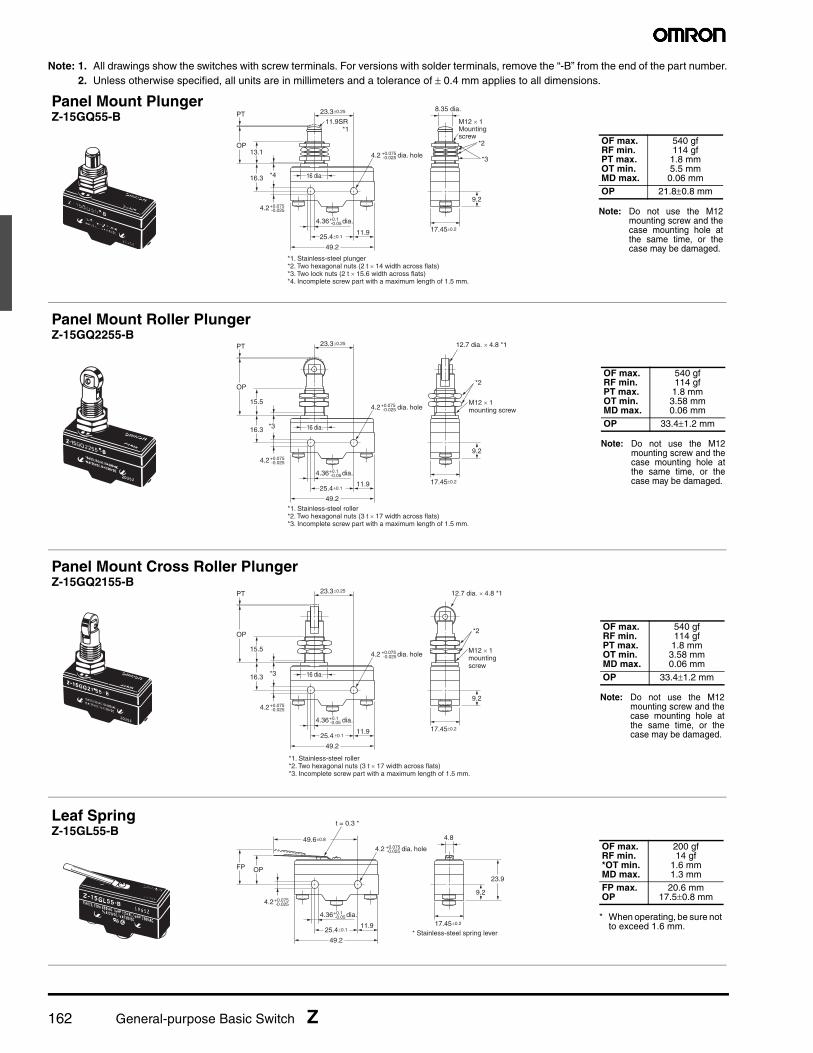
162 General-purpose Basic Switch Z
Note: 1. All drawings show the switches with screw terminals. For versions with solder terminals, remove the “-B” from the end of the part number.2. Unless otherwise specified, all units are in millimeters and a tolerance of ± 0.4 mm applies to all dimensions.
49.2
11.925.4±0.1
23.3±0.25
OP
PT8.35 dia.
11.9SR *1
*1. Stainless-steel plunger*2. Two hexagonal nuts (2 t × 14 width across flats)*3. Two lock nuts (2 t × 15.6 width across flats)*4. Incomplete screw part with a maximum length of 1.5 mm.
*416.3
13.1*2
*3
M12 × 1Mountingscrew
9.2
17.45±0.2
4.2+0.075-0.025
4.2 dia. hole+0.075-0.025
4.36 dia.+0.1-0.05
16 dia.
Panel Mount PlungerZ-15GQ55-B
Note: Do not use the M12mounting screw and thecase mounting hole atthe same time, or thecase may be damaged.
OF max.RF min.PT max.OT min.MD max.
540 gf114 gf
1.8 mm5.5 mm0.06 mm
OP 21.8±0.8 mm
49.2
11.925.4±0.1
23.3±0.25
OP
PT
*1. Stainless-steel roller*2. Two hexagonal nuts (3 t × 17 width across flats)*3. Incomplete screw part with a maximum length of 1.5 mm.
*316.3
15.5
*2
12.7 dia. × 4.8 *1
M12 × 1mounting screw
9.2
17.45±0.2
4.2+0.075-0.025
4.2 dia. hole+0.075-0.025
4.36 dia.+0.1-0.05
16 dia.
Panel Mount Roller PlungerZ-15GQ2255-B
Note: Do not use the M12mounting screw and thecase mounting hole atthe same time, or thecase may be damaged.
OF max.RF min.PT max.OT min.MD max.
540 gf114 gf1.8 mm3.58 mm0.06 mm
OP 33.4±1.2 mm
17.45±0.2
4.2+0.075-0.025
4.2 dia. hole+0.075-0.025
4.36 dia.+0.1-0.05
49.2
11.925.4 ±0.1
23.3±0.25
OP
PT
*1. Stainless-steel roller*2. Two hexagonal nuts (3 t × 17 width across flats)*3. Incomplete screw part with a maximum length of 1.5 mm.
*316.3
15.5
*2
12.7 dia. × 4.8 *1
16 dia.
M12 × 1mountingscrew
9.2
Panel Mount Cross Roller PlungerZ-15GQ2155-B
Note: Do not use the M12mounting screw and thecase mounting hole atthe same time, or thecase may be damaged.
OF max.RF min.PT max.OT min.MD max.
540 gf114 gf
1.8 mm3.58 mm0.06 mm
OP 33.4±1.2 mm
49.2
11.925.4±0.1
49.6±0.8
23.9OPFP
4.8
* Stainless-steel spring lever
t = 0.3 *
9.2
17.45±0.2
4.2+0.075-0.025
4.2 dia. hole+0.075-0.025
4.36 dia.+0.1-0.05
Leaf SpringZ-15GL55-B
* When operating, be sure not to exceed 1.6 mm.
OF max.RF min.*OT min.MD max.
200 gf14 gf
1.6 mm1.3 mm
FP max.OP
20.6 mm17.5±0.8 mm
General-purpose Basic Switch Z 163
Note: 1. All drawings show the switches with screw terminals. For versions with solder terminals, remove the “-B” from the end of the part number.2. Unless otherwise specified, all units are in millimeters and a tolerance of ± 0.4 mm applies to all dimensions.
49.2
11.925.4±0.1
46 ±0.8
23.9
OPFP
* Stainless-steel lever
t = 0.3*
9.5 dia. × 4(plastic roller)
9.2
17.45 ±0.2
4.2+0.075-0.025
4.2 dia. hole+0.075-0.025
4.36 dia.+0.1-0.05
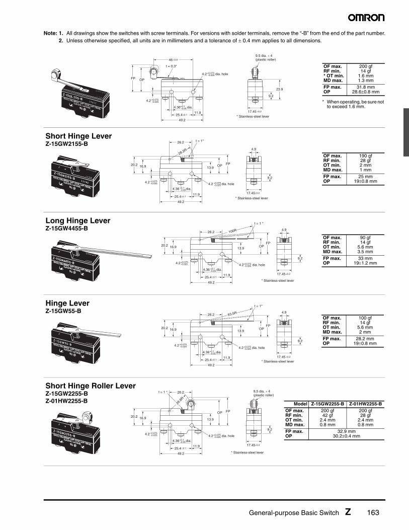
* When operating, be sure not to exceed 1.6 mm.
OF max.RF min.* OT min.MD max.
200 gf14 gf
1.6 mm1.3 mm
FP max.OP
31.8 mm28.6±0.8 mm
49.2
11.925.4±0.1
26.2
OP FP
4.9
* Stainless-steel lever
t = 1*
20.2 16.9 13.9
28.2R
9.2
17.45±0.2
4.2+0.075-0.025 4.2 dia. hole+0.075
-0.025
4.36 dia.+0.1-0.05
Short Hinge LeverZ-15GW2155-B
OF max.RF min.OT min.MD max.
190 gf28 gf2 mm1 mm
FP max.OP
25 mm19±0.8 mm
49.2
11.925.4 ±0.1
26.2
17.45±0.2
OPFP
4.9
* Stainless-steel lever
t = 1 *
20.2 16.9 13.9
100R
9.24.2+0.075
-0.025
4.36 dia.+0.1 -0.05
4.2 dia. hole+0.075-0.025
Long Hinge LeverZ-15GW4455-B
OF max.RF min.OT min.MD max.
90 gf14 gf
5.6 mm3.5 mm
FP max.OP
33 mm19±1.2 mm
49.2
11.925.4 ±0.1
26.2
OPFP
4.9
* Stainless-steel lever
t = 1*
20.2 16.9 13.9
63.5R
9.2
17.45 ±0.2
4.2+0.075-0.025 4.2 dia. hole+0.075
-0.025
4.36 dia.+0.1-0.05
Hinge LeverZ-15GW55-B
OF max.RF min.OT min.MD max.
100 gf14 gf
5.6 mm2 mm
FP max.OP
28.2 mm19±0.8 mm
49.2
11.925.4 ±0.1
26.2
17.45±0.2
OP FP
* Stainless-steel lever
t = 1 *
20.2 16.9 13.9
26.6
R
9.5 dia. × 4(plastic roller)
9.24.2+0.075
-0.025 4.2 dia. hole+0.075-0.025
4.36 dia.+0.1-0.05
Short Hinge Roller LeverZ-15GW2255-BZ-01HW2255-B Model Z-15GW2255-B Z-01HW2255-B
OF max.RF min.OT min.MD max.
200 gf42 gf
2.4 mm0.8 mm
200 gf28 gf
2.4 mm0.8 mm
FP max.OP
32.9 mm30.2±0.4 mm

164 General-purpose Basic Switch Z
Note: 1. All drawings show the switches with screw terminals. For versions with solder terminals, remove the “-B” from the end of the part number.2. Unless otherwise specified, all units are in millimeters and a tolerance of ± 0.4 mm applies to all dimensions.
* The pin plungers of reverse-type models are continuously pressed by the actuator levers with compression coil springs and the pin plungers are freed by operating the levers.
49.2
11.925.4 ±0.1
26.2
OPFP
* Stainless-steel lever
t = 1 *
20.2 16.9 13.9
48.5R9.5 dia. × 4(plastic roller)
9.2
17.45±0.2
4.2+0.075-0.025 4.2 dia. hole+0.075
-0.025
4.36 dia.+0.1-0.05
Hinge Roller LeverZ-15GW255-B
OF max.RF min.OT min.MD max.
130 gf21 gf4 mm
1.6 mmFP max.OP
36.5 mm30.2±0.8 mm
49.2
11.925.4±0.1
26.2
Operating direction
OP FP
* Stainless-steel lever
t = 1 *
20.2
34.1 max.
16.9 13.9
9.5 dia. × 4(plastic roller)
11.1R31
.9R
9.2
17.45 ±0.2
4.2+0.075-0.025 4.2 dia. hole+0.075
-0.025
4.36 dia.+0.1-0.05
Unidirectional Short Hinge Roller LeverZ-15GW227755-B
OF max.RF min.OT min.MD max.
180 gf50 gf
2.4 mm0.8 mm
FP max.OP
43.6 mm41.3±0.8 mm
49.2
11.925.4 ±0.1
18.65 56R
17.45 ±0.2
4.9
OP FP
* Stainless-steel lever
t = 1 *
20.2 17.4 13.9
9.24.2+0.075
-0.025 4.2 dia. hole+0.075-0.025
4.36 dia.+0.1-0.05
Reverse Hinge Lever *Z-15GM55-B
OF max.RF min.OT min.MD max.
200 gf28 gf
5.6 mm0.89 mm
FP max.OP
23.8 mm19±0.8 mm
49.2
11.925.4±0.1
18.65
17.45±0.2
OP FP
* Stainless-steel lever
t = 1 *
20.2 17.4 13.9
18.5
R
9.5 dia. × 4(plastic roller)
9.24.2+0.075
-0.025 4.2 dia. hole+0.075-0.025
4.36 dia.+0.1-0.05
Reverse Short Hinge Roller Lever *Z-15GM2255-B
OF max.RF min.OT min.MD max.
580 gf170 gf2 mm
0.28 mmFP max.OP
31.8mm29.4±0.4mm
17.45 ±0.2
9.5 dia. × 4(plastic roller)
49.2
11.925.4 ±0.1
18.65
OPFP
* Stainless-steel lever
t = 1 *
20.2 17.4 13.9
40.6R
9.24.2+0.075
-0.025 4.2 dia. hole+0.075-0.025
4.36 dia.+0.1-0.05
Reverse Hinge Roller Lever *Z-15GM255-B
OF max.RF min.OT min.MD max.
270 gf56 gf4 mm
0.64 mmFP max.OP
35 mm30.2±0.8 mm

General-purpose Basic Switch Z 165
Note: 1. All drawings show the switches with screw terminals. For versions with solder terminals, remove the “-B” from the end of the part number.2. Unless otherwise specified, all units are in millimeters and a tolerance of ± 0.4 mm applies to all dimensions.
17.45±0.2
12 dia.
49.2
11.925.4±0.1
23.3±0.25
PT
Rubber cap
30 Operating range *2
Nylon rod
3.2 dia.
6.1 dia.
38
43.4
(13.6)
16.3
(111.3)
*1
*1. Operation is possible in any direction other than the axial direction (indicated by the arrow ).*2. Use only the area within the top 30 mm of the rod as the operating part. (Do not use the area that falls within 80 mm from the mounting hole as the operating part. Using this area may cause damage to the nylon rod.
9.24.2+0.075
-0.025
4.2 dia. hole+0.075-0.025
4.36 dia.+0.1-0.05
Flexible Rod (Coil Spring)Z-15GNJ55-B
OF max.PT max.
50 gf(20 mm)
TT max. 40 mm
49.2
11.925.4 ±0.1
23.3±0.25
17.45±0.2
PT
12 dia.Rubber cap
Four, M3 set screwswith hexagonal holes
30 Operating range *2
1-dia. stainlesssteel wire *3
100±0.4
(13.8)
(22)
16.3
(130.1)
*1
*1. Operation is possible in any direction other than the axial direction (indicated by the arrow ).*2. Use only the area within the top 30 mm of the rod as the operating part. (Do not use the area that falls within 100 mm from the mounting hole as the operating part. Using this area may cause damage to the steel wire.)*3. The steel wire can be replaced if damaged. (Model: Lever for HNJS55)
9.24.2+0.075
-0.025
4.36 dia.+0.1 -0.05
4.2 dia. hole+0.075-0.025
Flexible Rod (Steel Wire)Z-15HNJS55-B
OF max.PT max.
15 gf(25 mm)
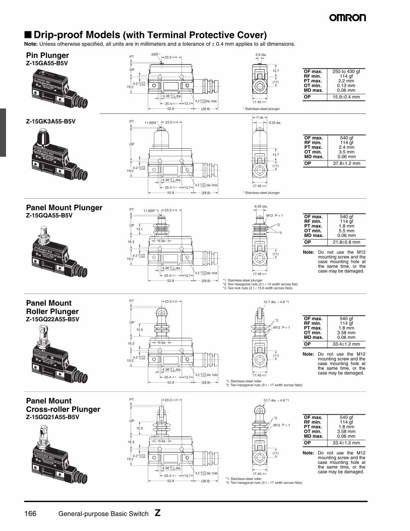
166 General-purpose Basic Switch Z
■ Drip-proof Models (with Terminal Protective Cover)Note: Unless otherwise specified, all units are in millimeters and a tolerance of ± 0.4 mm applies to all dimensions.
17.45 ±0.2
52.8
13.725.4 ±0.1
(11)
14.7
* Stainless-steel plunger
OP
(28.8)
PT 23.3 ±0.25 8.35 dia.11.9SR *
17 dia.
19.24.2+0.075
-0.025
4.2 dia. hole+0.075-0.025
4.36 dia.+0.1-0.05
Z-15GK3A55-B5V
OF max.RF min.PT max.OT min.MD max.
540 gf114 gf2.4 mm3.5 mm0.06 mm
OP 37.8±1.2 mm
52.8
13.7
23.3±0.25
(11)
14.7
3.9 dia.
* Stainless-steel plunger
OP
6SR *
(28.8)
PT
19.2
17.45 ±0.2
4.2+0.075-0.025
4.2 dia. hole+0.075-0.025
4.36 dia.+0.1-0.05
25.4 ±0.1
Pin PlungerZ-15GA55-B5V
OF max.RF min.PT max.OT min.MD max.
250 to 430 gf114 gf
2.2 mm0.13 mm0.06 mm
OP 15.9±0.4 mm
16 dia.
17.45±0.2
52.8
13.725.4±0.1
(11)
OP
(28.8)
PT 23.3±0.25
8.35 dia.11.9SR *1
19.2
16.3
13.1
*1. Stainless-steel plunger*2. Two hexagonal nuts (2 t × 14 width across flat)*3. Two lock nuts (2 t × 15.6 width across flats)
*2
*3
M12 P = 1
4.2+0.075-0.025
4.2 dia. hole+0.075-0.025
4.36 dia.+0.1-0.05
Panel Mount PlungerZ-15GQA55-B5V
Note: Do not use the M12mounting screw and thecase mounting hole atthe same time, or thecase may be damaged.
OF max.RF min.PT max.OT min.MD max.
540 gf114 gf1.8 mm5.5 mm0.06 mm
OP 21.8±0.8 mm
52.8
13.725.4 ±0.1
(11)
OP
(28.8)
PT 23.3±0.25
19.2
16.3
15.5
*1. Stainless-steel roller*2. Two hexagonal nuts (3 t × 17 width across flats)
16 dia.
*2
M12 P = 1
12.7 dia. × 4.8 *1
17.45±0.2
4.2+0.075-0.025
4.2 dia. hole+0.075-0.025
4.36 dia.+0.1-0.05
Panel Mount Roller PlungerZ-15GQ22A55-B5V
Note: Do not use the M12mounting screw and thecase mounting hole atthe same time, or thecase may be damaged.
OF max.RF min.PT max.OT min.MD max.
540 gf114 gf
1.8 mm3.58 mm0.06 mm
OP 33.4±1.2 mm
52.8
13.725.4 ±0.1
(11)
OP
(28.8)
PT 23.3 ±0.25
19.2
16.3
15.5
*1. Stainless-steel roller*2. Two hexagonal nuts (3 t × 17 width across flats)
16 dia.
*2
12.7 dia. × 4.8 *1
M12 P = 1
17.45 ±0.2
4.2+0.075-0.025
4.36 dia.+0.1 -0.05
4.2 dia. hole+0.075-0.025
Panel Mount Cross-roller PlungerZ-15GQ21A55-B5V
Note: Do not use the M12mounting screw and thecase mounting hole atthe same time, or thecase may be damaged.
OF max.RF min.PT max.OT min.MD max.
540 gf114 gf
1.8 mm3.58 mm0.06 mm
OP 33.4±1.2 mm
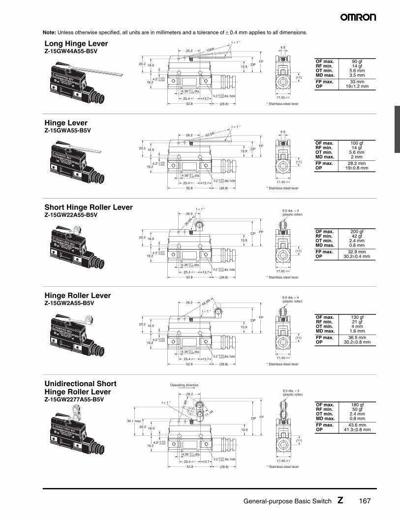
General-purpose Basic Switch Z 167
Note: Unless otherwise specified, all units are in millimeters and a tolerance of ± 0.4 mm applies to all dimensions.
52.8
13.725.4±0.1
26.2
OPFP
(11)
4.9
* Stainless-steel lever
t = 1 *
20.2 16.9
19.2
13.9
100R
(28.8)
17.45±0.2
4.2+0.075-0.025
4.2 dia. hole+0.075-0.025
4.36 dia.+0.1 -0.05
Long Hinge LeverZ-15GW44A55-B5V
OF max.RF min.OT min.MD max.
90 gf14 gf
5.6 mm3.5 mm
FP max.OP
33 mm19±1.2 mm
52.8
13.7 25.4±0.1
26.2
OPFP
(11)
4.9
* Stainless-steel lever
t = 1 *
20.2 16.9
19.2
13.9
63.5R
(28.8)
17.45±0.2
4.2+0.075-0.025
4.2 dia. hole +0.075-0.025
4.36 dia.+0.1-0.05
Hinge LeverZ-15GWA55-B5V
OF max.RF min.OT min.MD max.
100 gf14 gf
5.6 mm2 mm
FP max.OP
28.2 mm19±0.8 mm
52.8
13.725.4 ±0.1
26.2
17.45 ±0.2
OP FP
(11)
* Stainless-steel lever
t = 1 *
20.2 16.9
19.2
13.9
(28.8)
26.6
R
9.5 dia. × 4(plastic roller)
4.2+0.075-0.025
4.36 dia.+0.1 -0.05
4.2 dia. hole+0.075-0.025
Short Hinge Roller LeverZ-15GW22A55-B5V
OF max.RF min.OT min.MD max.
200 gf42 gf
2.4 mm0.8 mm
FP max.OP
32.9 mm30.2±0.4 mm
52.8
13.725.4 ±0.1
26.2
17.45±0.2
OPFP
(11)
* Stainless-steel lever
20.2 16.9
19.2
13.9
(28.8)
9.5 dia. × 4(plastic roller)
t = 1 *
48.5R
4.2+0.075-0.025
4.36 dia.+0.1 -0.05
4.2 dia. hole+0.075-0.025
Hinge Roller LeverZ-15GW2A55-B5V
OF max.RF min.OT min.MD max.
130 gf21 gf4 mm
1.6 mmFP max.OP
36.5 mm30.2±0.8 mm
52.8
13.725.4 ±0.1 17.45±0.2
OP FP
(11)
* Stainless-steel lever
20.2 16.9
19.2
13.9
(28.8)
9.5 dia. × 4(plastic roller)26.2
Operating direction
t = 1 *
11.1R
31.9
R
34.1 max.
4.2+0.075-0.025
4.2 dia. hole+0.075 -0.025
4.36 dia.+0.1 -0.05
Unidirectional Short Hinge Roller LeverZ-15GW2277A55-B5V
OF max.RF min.OT min.MD max.
180 gf50 gf
2.4 mm0.8 mm
FP max.OP
43.6 mm41.3±0.8 mm

168 General-purpose Basic Switch Z
■ Drip-proof Models (with Molded Terminal Cover)Note: Unless otherwise specified, all units are in millimeters and a tolerance of ± 0.4 mm applies to all dimensions.
L/R Type (The following illustration is the R type.) D Type
Lead Wire Specifications
Note: 1. No models with molded terminals are approved by UL, CSA, or EN.2. Molded terminals are not available on all models. Contact your OMRON representative for applicable products.
■ Maintained Contact ModelsNote: Unless otherwise specified, all units are in millimeters and a tolerance of ± 0.4 mm applies to all dimensions.
a
b 38 5
c
Size (mm) Lead wire a b c
VSF 12 4 13
VCT 19 11 20
a
b cSize (mm)
Lead wire a b c
VSF 12 4 12
VCT 19 11 16
SpecificationsLead wire Nominal cross sectional area (mm2) Finished outer diameter (mm) Connection to terminal Length (m)
VSF (single-core, vinyl cord)1.25
Approx. 3.1 dia. Black: COMWhite: NORed: NC
1, 3VCT (vinyl-insulated cable) Three-core:
approx. 10.5 dia.
COMNO
NC
49.2
11.925.4±0.1
23.3 ±0.25
Reset freeposition9.5 max.17.45±0.2
OP
PT2.3 dia.
2.3SR *1
*1. Stainless steel plunger*2. Plastic plunger
Reset position7.1 min.
6.4 dia.Reset button *2
6.4
21.4
14.3±0.3
4.2+0.075-0.025
4.2 dia. hole+0.075 -0.025
4.36 dia.+0.1 -0.05
Pin PlungerZ-15ER Plunger
Reset Button
OFPT max.OT min.
200 to 255 gf0.4 mm0.13 mm
OP 15.9±0.4 mm
OFmax.OTmin.
56 to 285 gf0.4 mm
5.2 dia.
4 dia.
49.2
11.925.4 ±0.1
Reset freeposition 9.5 max.
17.45±0.2
*1. Stainless steel plunger (tip only, flat, R1 bevel).*2. Plastic plunger
Reset position7.1 min.
6.4 dia.
Reset button *2
6.4
21.4
14.3 ±0.3
23.3 ±0.25
*1
OP
PT
9 dia.
4.2+0.075-0.025
4.2 dia. hole+0.075 -0.025
4.36 dia.+0.1 -0.05
Slim Spring PlungerZ-15ESR Plunger
Reset Button
OF max.PT max.OT min.
270 gf0.4 mm1.6 mm
OP 28.2±0.5 mm
OF max.OT min.
285 gf0.4 mm
49.2
11.925.4 ±0.1
Reset freeposition9.5 max.17.45±0.2
*1. Stainless steel lever*2. Plastic plunger
4.2+0.075-0.025
4.2 dia. hole+0.075-0.025
4.36 dia.+0.1 -0.05
Reset position7.1 min.
6.4 dia.Reset button *2
6.4
14.3 ±0.3
t = 1 *1
26.2
20.2 16.9
4.9
OPFP
13.9
63.5R
Hinge LeverZ-15EWR
Lever Tip
Reset Button
OF max.OT min.
55 gf5.6 mm
FP max.OP
28.2 mm19±0.8 mm
OF max.OT min.
300 gf0.4 mm
General-purpose Basic Switch Z 169
Safety PrecautionsBe sure to read the precautions and information common to all Snap Action and Detection Switches, contained in the Technical User’s Guide, “Snap Action Switches, Technical Information” for correct use.
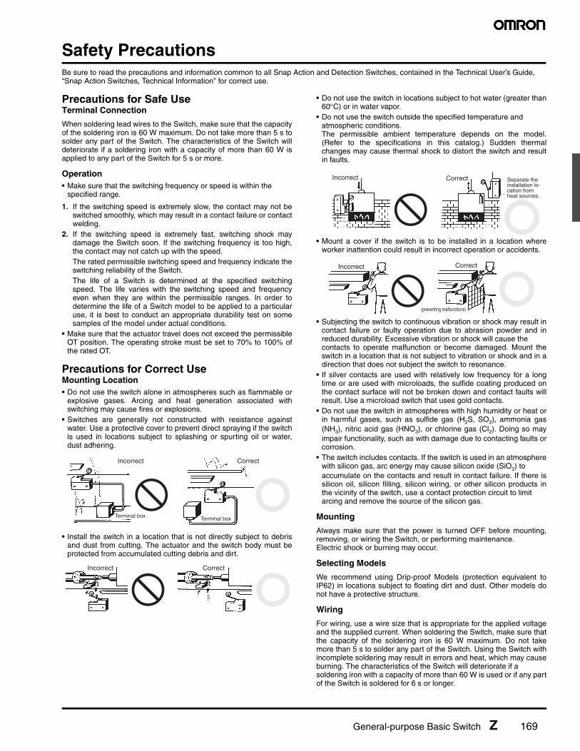
Precautions for Safe UseTerminal Connection
When soldering lead wires to the Switch, make sure that the capacityof the soldering iron is 60 W maximum. Do not take more than 5 s tosolder any part of the Switch. The characteristics of the Switch willdeteriorate if a soldering iron with a capacity of more than 60 W isapplied to any part of the Switch for 5 s or more.
Operation• Make sure that the switching frequency or speed is within the
specified range.
1. If the switching speed is extremely slow, the contact may not beswitched smoothly, which may result in a contact failure or contactwelding.
2. If the switching speed is extremely fast, switching shock maydamage the Switch soon. If the switching frequency is too high,the contact may not catch up with the speed.The rated permissible switching speed and frequency indicate theswitching reliability of the Switch.The life of a Switch is determined at the specified switchingspeed. The life varies with the switching speed and frequencyeven when they are within the permissible ranges. In order todetermine the life of a Switch model to be applied to a particularuse, it is best to conduct an appropriate durability test on somesamples of the model under actual conditions.
• Make sure that the actuator travel does not exceed the permissibleOT position. The operating stroke must be set to 70% to 100% ofthe rated OT.
Precautions for Correct UseMounting Location• Do not use the switch alone in atmospheres such as flammable or
explosive gases. Arcing and heat generation associated withswitching may cause fires or explosions.
• Switches are generally not constructed with resistance againstwater. Use a protective cover to prevent direct spraying if the switchis used in locations subject to splashing or spurting oil or water,dust adhering.
• Install the switch in a location that is not directly subject to debrisand dust from cutting. The actuator and the switch body must beprotected from accumulated cutting debris and dirt.
• Do not use the switch in locations subject to hot water (greater than60°C) or in water vapor.
• Do not use the switch outside the specified temperature and atmospheric conditions.The permissible ambient temperature depends on the model.(Refer to the specifications in this catalog.) Sudden thermalchanges may cause thermal shock to distort the switch and resultin faults.
• Mount a cover if the switch is to be installed in a location whereworker inattention could result in incorrect operation or accidents.
• Subjecting the switch to continuous vibration or shock may result incontact failure or faulty operation due to abrasion powder and inreduced durability. Excessive vibration or shock will cause the contacts to operate malfunction or become damaged. Mount theswitch in a location that is not subject to vibration or shock and in adirection that does not subject the switch to resonance.
• If silver contacts are used with relatively low frequency for a longtime or are used with microloads, the sulfide coating produced onthe contact surface will not be broken down and contact faults willresult. Use a microload switch that uses gold contacts.
• Do not use the switch in atmospheres with high humidity or heat orin harmful gases, such as sulfide gas (H2S, SO2), ammonia gas(NH3), nitric acid gas (HNO3), or chlorine gas (Cl2). Doing so mayimpair functionality, such as with damage due to contacting faults orcorrosion.
• The switch includes contacts. If the switch is used in an atmospherewith silicon gas, arc energy may cause silicon oxide (SiO2) to accumulate on the contacts and result in contact failure. If there issilicon oil, silicon filling, silicon wiring, or other silicon products inthe vicinity of the switch, use a contact protection circuit to limit arcing and remove the source of the silicon gas.
Mounting
Always make sure that the power is turned OFF before mounting,removing, or wiring the Switch, or performing maintenance.Electric shock or burning may occur.
Selecting Models
We recommend using Drip-proof Models (protection equivalent toIP62) in locations subject to floating dirt and dust. Other models donot have a protective structure.
Wiring
For wiring, use a wire size that is appropriate for the applied voltageand the supplied current. When soldering the Switch, make sure thatthe capacity of the soldering iron is 60 W maximum. Do not takemore than 5 s to solder any part of the Switch. Using the Switch withincomplete soldering may result in errors and heat, which may causeburning. The characteristics of the Switch will deteriorate if a soldering iron with a capacity of more than 60 W is used or if any partof the Switch is soldered for 6 s or longer.
Terminal box Terminal box
Incorrect Correct
Incorrect Correct
Incorrect Separate the installation lo-cation from heat sources.
Correct
Correct
(preventing malfunctions)
Incorrect

170 General-purpose Basic Switch Z
Tightening
The suitable tightening torque for screw terminals is given below.
• Screw terminals except for those on Split-contact Models (Z-10FY-B): 0.78 to 1.18 N·m
• Screw terminals on Split-contact Models (Z-10FY-B): 0.49 to 1.18 N·m
Operation• Make sure that the switching speed and frequency are is within the
specified ranges.
1. If the switching speed is extremely slow, the contacts may not beswitched smoothly, which may result in a contact failure or contactwelding.
2. If the switching speed is extremely fast, switching shock maydamage the Switch prematurely. If the switching frequency is toohigh, the contacts may not be able to keep up with the speed.The rated permissible switching speed and frequency indicate theswitching reliability of the Switch.The life of a Switch is determined at the specified switchingspeed. The life varies with the switching speed and frequencyeven when they are within the permissible ranges. Always conduct appropriate durability tests under actual condi-tions before using a Switch.
• Make sure that the actuator travel does not exceed the permissibleOT position. The operating stroke must be set to 70% to 100% ofthe rated OT.
Panel Mount Switch (Z-15@Q@, Z-01@Q@)• When mounting the panel mount plunger model with screws on a
side surface, be careful of the dog angle and operation speed.Excessive dog angle or operation speed may damage the Switch.
• When using the panel mount plunger model mounted with screwson a side surface, be careful not to apply a large shock. Applying ashock exceeding 1,000 m/s2 may damage the Switch.
• When using the panel mount plunger model mounted with screwson a side surface, remove the hexagonal nuts from the actuator.
High-sensitivity Switch (Z-15H)/ Extra-high-sensitivity Switch (Z-15H2)• When using the Switch in a DC circuit, be sure to provide an arc
suppressor as well because the small contact gap of the Switchmay result in contact troubles.
• In an application where a high repeat accuracy is required, limit thecurrent that flows through the Switch to within 0.1 A. Also, use arelay to control a high-capacity load if the Switch is connected tosuch a load. (In this case, the exciting current of the relay coil is theload of the Switch.)
• Do not apply a force of 19.6 N or higher to the pin plunger.• Exercise care that the environment conditions such as temperature
and humidity do not change abruptly.
Micro Load Applicable Range
Using a model for ordinary loads to open or close the contact of amicro load circuit may result in faulty contact. Use models that operate in the following range. However, even when using micro loadmodels within the operating range shown here, if inrush currentoccurs when the contact is opened or closed, it may increase contactwear and so decrease durability. Therefore, insert a contact protection circuit where necessary.
The minimum applicable load is the N-level reference value. Thisvalue indicates the malfunction reference level for the reliability levelof 60% (λ60). The equation, λ60 = 0.5×10⁻⁶/operations indicates thatthe estimated malfunction rate is less than 1/2,000,000 operationswith a reliability level of 60%.
Models with Drip-proof Terminal Cover (Z-@A55-B5V) Wiring• To attach the Protective Cover to the case, hold the cover in almost
parallel to the case and then push it to the case. If the cover ispushed diagonally, the rubber packing may slip off, degrading thesealability of the Switch.
• Use round solderless terminals having the following dimensions toconnect leads to the terminals. Tighten the screws of terminals to atorque of 0.78 to 1.18 N·m. Use the terminal shown below.
• A cable 8.5 to 10.5 mm in diameter can be applicable to the sealingrubber of the lead outlet of the Switch. A two-core or three-coreVCT cable having a cross-sectional area of 1.25 mm2 is especiallysuitable for this.
• M4 small screws with spring toothed washer are used as the termi-nal screws.
Z-01H Z-15@, Z-10FY
Minimum applicable load 1 mA at 5 VDC 160 mA at 5 VDC
30
24
12
5
01 10 100 1,000
Current (mA)
0.1
1 mA
Operatingrange forgeneral loadmodelsZ-15H, H2Z-15GZ-15EZ-10FYZ-15ER
Operating rangefor micro loadmodels Z-01H
26 mA0.16 mA
800 mW5 mW
100 mA 160 mA
Unusablerange
DC
vol
tage
(V
)
Terminal withtoothedwasher
Rubber packing
4.3 dia.
20 max.
8

General-purpose Basic Switch Z 171
Drip-proof Switch (Z-@55)• The Switch is not perfectly oil-tight; so do not dip it in oil or water.• The rubber boots are made from weather-resistive chloroprene rubber.• Do not use Basic Switches in places with radical changes in temperature.• Rubber boots and rubber caps will tend to harden at lower ambient
temperatures. If an Actuator is used in a pressed state for anextended period of time at low temperatures, it may return slowly orit may not return at all. OMRON can provide special Actuators foruse at low temperature with rubber boots or rubber caps made ofsilicon rubber, which has superior resistance to cold. Ask yourOMRON representative for details.
Split-contact Switch (Z-10F@Y)
The applicable current varies depending on how the contacts areused. If the Switch is connected in series, the Switch can endure acurrent 1.5 to 2 times higher than the current that can be applied inparallel connection.
Flexible Rod Switch (Z-15@NJ@55, Drip-proof)• When the rod is fully swung, the Switch may operate when the lever
returns, causing chattering. Use a circuit that compensates forchattering wherever possible.
• Do not switch the rod to the fullest extent when the Switch is tobreak a power circuit because such a practice may cause metaldeposition to occur between the mating contacts of the Switch.
Other Precautions• Do not apply excessive force with a screwdriver or other tool when
attaching or removing the Protective Cover. Doing so may deformthe Switch.
• The Drip-proof Terminal Protective Cover (AP-DV) can be usedonly with Switches with model numbers ending in “-B5V.”
• The Drip-proof Terminal Protective Cover is only available for maintenance purposes.
Accessories (Order Separately)Refer to “Z/A/X/DZ Common Accessories” datasheet for details about Terminal Covers, Separators, and Actuators.
The Drip-proof Terminal Protective Cover is provided for maintenance for Z-@A55-B5V Switches.
Screwdriver
Drip-proof Terminal Cover (Order Separately)
Ordering Information
Name Model
Drip-proof Terminal Protective Cover AP-DV
Dimensions (Unit: mm)
48.5+1-2
51.60.6 929.5±1
15
7.5
11
17.4
17.4
27.9
Mounting bracket
17.4
17 dia.13.5 dia.

General-purpose Basic Switch Z
OMRON ON-LINEGlobal - http://www.omron.comUSA - http://www.components.omron.com
Cat. No. X303-E-1 Printed in USA
OMRON ELECTRONIC COMPONENTS LLC55 E. Commerce Drive, Suite BSchaumburg, IL 60173
847-882-228811/10 Specifications subject to change without notice
All sales are subject to Omron Electronic Components LLC standard terms and conditions of sale, which can be found at http://www.components.omron.com/components/web/webfiles.nsf/sales_terms.html
ALL DIMENSIONS SHOWN ARE IN MILLIMETERS.To convert millimeters into inches, multiply by 0.03937. To convert grams into ounces, multiply by 0.03527.
Mouser Electronics
Authorized Distributor
Click to View Pricing, Inventory, Delivery & Lifecycle Information: Omron:
Z-15GQ55 Z-15GW255 Z-15GW2255-B6-106-K Z-15GW2255M19D1M Z-15GW2255-M19D3M Z-
15GW2255M19L1M Z-15GW2255M19R1M Z-15GS55 Z-15GW2255M19D-1M Z-15GW2255-M19D-3M Z-
15GW2255M19L-1M Z-15GW2255M19R-1M Z-10FM22Y-B Z-15GNJ55-MR2 0.5M Z-15EQ22R-1 Z-15E Z-15GW21
Z-15HW7855 Z-15EW565 Z-15G55 Z-10FDY-B Z-15GQ8 Z-15GW-BT Z-15GW4455 Z-15H2 Z-15GQ-B74-K Z-
15GW32 Z-15GK3A55-B5V Z-10FW22Y255-B6-105-K1 Z-01HD55-B Z-01HW2255-B Z-01H55-B Z-15GK556-MR
2M