model pm-616 two-color pyrometer operator’s manual revision...
TRANSCRIPT
Model PM-616 Two-Color Pyrometer
Operator’s Manual
Revision 1.2
Logika Technologies Inc.
2857 Sherwood Heights Dr. Unit 2
Oakville ON, CanadaL6J 7J9
Tel: 905-829-5841
www.logikatech.com
Web: www.logikatech.com Phone: 905-829-5841 Fax: 905-829-8787 Email: [email protected]
P a g e | 1
Logika Technologies PM-616 Two-color Pyrometer Operator’s Manual Rev. 1.2 Feb-13
1 INTRODUCTION .................................................................................................. 2
2 DESCRIPTION ...................................................................................................... 2
2.1 MODEL NOMENCLATURE ................................................................................................................. 2
2.2 OPERATING PRINCIPLE ..................................................................................................................... 3
2.3 SPECIFICATIONS.............................................................................................................................. 3
3 LOCATION AND MOUNTING ............................................................................... 5
3.1 PYROMETER LOCATION .................................................................................................................... 5
3.2 PYROMETER MOUNTING .................................................................................................................. 7
3.3 LENS WITH FIBER OPTIC CABLE........................................................................................................... 7
4 UTILITY CONNECTIONS ....................................................................................... 8
4.1 ELECTRICAL CONNECTIONS ............................................................................................................... 8
4.2 WATER COOLING CONNECTION ......................................................................................................... 9
4.3 PURGE AIR CONNECTION ............................................................................................................... 10
5 OPERATION ...................................................................................................... 11
5.1 CONTROLS .................................................................................................................................. 11
5.2 SET MENU FUNCTIONS AND PROGRAMMING ..................................................................................... 11
Set Menu 1- Emissivity/Slope Adjustment ................................................................................ 12
Set Menu 2- Display Mode ........................................................................................................ 17
Set Menu 3– Output Signal Integration Time ........................................................................... 19
Set Menu 4-, 5-, 6- Process Alarm Settings ............................................................................... 20
Set Menu 7-, 8- Current/Voltage Analog Output Span Settings ............................................... 20
Set Menu 9- Aiming Laser Setup ............................................................................................... 21
Display Menu 10- Enclosure Temperature ............................................................................... 21
Display Menu 11- Two Color Ratio ............................................................................................. 22
Set Menu 12- Zero Compensation Gain ................................................................................... 22
Set Menu 13- Two-color mode signal attenuation ratio ........................................................... 22
5.3 DEBUGGING ................................................................................................................................ 24
6 MAINTENANCE ................................................................................................. 26
6.1 REGULAR MAINTENANCE ............................................................................................................... 26
6.2 INSTRUMENT RETURN ................................................................................................................... 26
7 APPENDIX ......................................................................................................... 27
Web: www.logikatech.com Phone: 905-829-5841 Fax: 905-829-8787 Email: [email protected]
P a g e | 2
Logika Technologies PM-616 Two-color Pyrometer Operator’s Manual Rev 1.2 Feb-13
1 Introduction
PM-616 two-color infrared pyrometer is primarily used in the metallurgical industry to
measure temperature of steel or molten iron, wire rod, hot rolled steel, as well as cement kilns.
The pyrometer can “look” into a process and measure the target temperature from a distance,
providing an accurate reading while eliminating problems associated with contact measuring
devices. Dual infrared wavelengths input signals overcome application challenges such as
small targets, variable emissivity, dust, water or other interfering media between the target
and the pyrometer. Accurate temperatures are obtained even when the target is 95%
obstructed.
PM-616 pyrometer also has a fiber optic option to utilize in applications with high
electromagnetic interference or high temperatures. The lens and fiber optic cable can
withstand up to 300°C with air purge connected.
2 Description
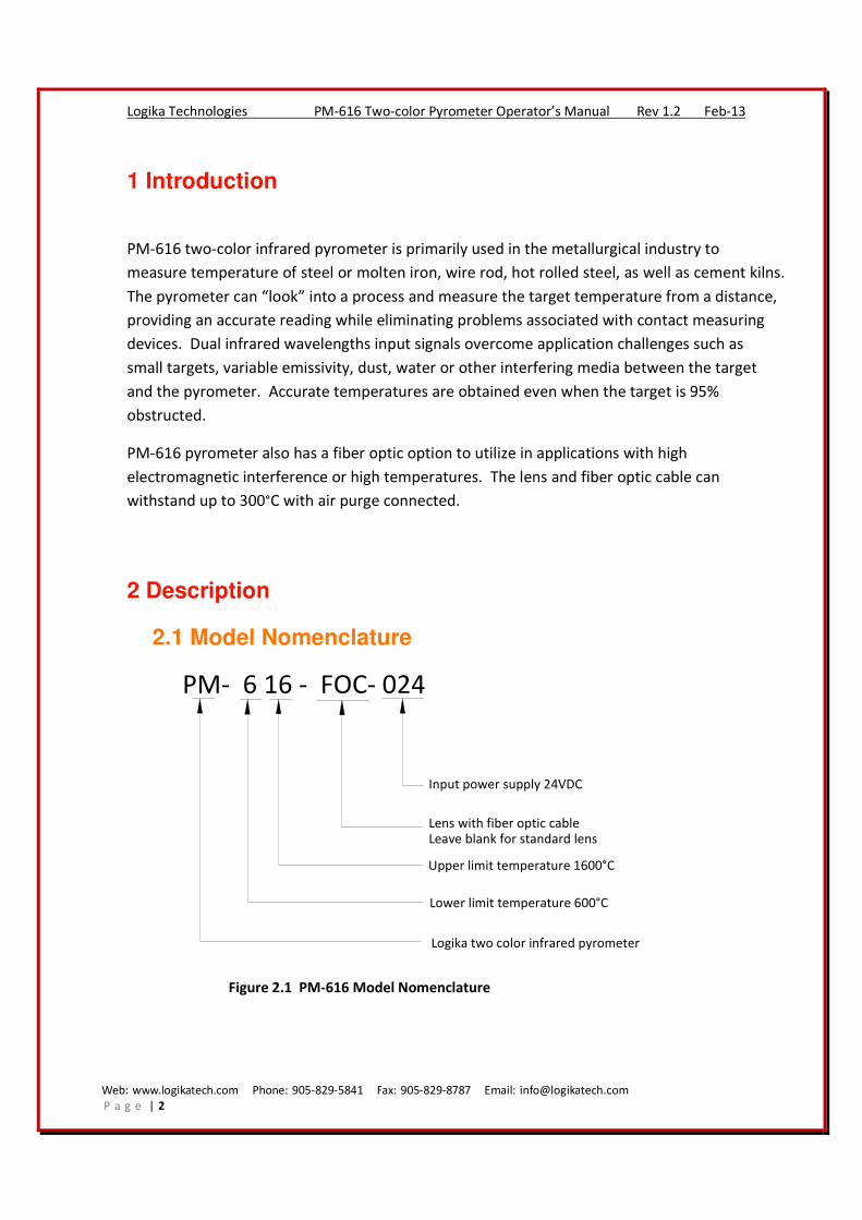
2.1 Model Nomenclature
PM- 6 16 - FOC- 024
Logika two color infrared pyrometer
Lower limit temperature 600°C
Upper limit temperature 1600°C
Lens with fiber optic cableLeave blank for standard lens
Input power supply 24VDC
Figure 2.1 PM-616 Model Nomenclature

Web: www.logikatech.com Phone: 905-829-5841 Fax: 905-829-8787 Email: [email protected]
P a g e | 3
Logika Technologies PM-616 Two-color Pyrometer Operator’s Manual Rev 1.2 Feb-13
2.2 Operating Principle
Logika PM-616 pyrometer uses a state-of-the-art photodiode to sense the infrared energy
from the target. Our pyrometer measures infrared energy emitted by the target at two
wavelengths and calculates the ratio of these measurements to determine the target
temperature. Since the emissivity of the two wavelengths is identical in same environment, it
does not influence the accuracy of the temperature measurement.
The primary advantage of PM-616 over thermocouple temperature measurement is that the
pyrometer accurately measures the target temperature by way of non contact means and
responses much faster.
Compared with single wavelength pyrometers, the advantages of the Logika PM-616 two-color
pyrometer are:
1. Overcomes optical fouling or interfering media between the target and the pyrometer,
such as dust, dirt, smoke, and water vapor, to yield accurate temperatures.
2. Automatically compensates for changes in target emissivity or varying distances between
the target and pyrometer.
3. Almost no restrictions to pyrometer’s field of view, leaving more flexibility for pyrometer
mounting. The PM-616 can accurately measure the target temperature even with as little
as 5% of the field of view.
4. PM-616 can also switch to single color mode for special field applications.
The PM-616 also has built-in temperature slope adjustment for calibrating the pyrometer to
the specific characteristics of the target metallurgy, and a visible target aiming laser for easy
installation. See Section 5.2.
2.3 Specifications
Power Input 24 VDC ±10% @ 210 mA
Power loss
protection
Reinstates all previous setup parameters when power is restored
Wavelength
One-color mode: 0.75-1.1μm
Two-color mode: 0.75-1.1μm and 1.1μm
Response time Adjustable – the fastest response time is 20 ms
Web: www.logikatech.com Phone: 905-829-5841 Fax: 905-829-8787 Email: [email protected]
P a g e | 4
Logika Technologies PM-616 Two-color Pyrometer Operator’s Manual Rev 1.2 Feb-13
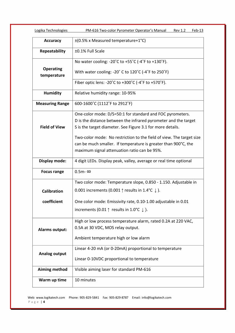
Accuracy ±(0.5% x Measured temperature+1°C)
Repeatability ±0.1% Full Scale
Operating
temperature
No water cooling: -20˚C to +55˚C (-4˚F to +130˚F).
With water cooling: -20˚ C to 120˚C (-4˚F to 250˚F)
Fiber optic lens: -20˚C to +300˚C (-4˚F to +570˚F).
Humidity Relative humidity range: 10-95%
Measuring Range 600-1600˚C (1112˚F to 2912˚F)
Field of View
One-color mode: D/S=50:1 for standard and FOC pyrometers.
D is the distance between the infrared pyrometer and the target
S is the target diameter. See Figure 3.1 for more details.
Two-color mode: No restriction to the field of view. The target size
can be much smaller. If temperature is greater than 900°C, the
maximum signal attenuation ratio can be 95%.
Display mode: 4 digit LEDs. Display peak, valley, average or real time optional
Focus range 0.5m- ∞
Calibration
coefficient
Two color mode: Temperature slope, 0.850 - 1.150. Adjustable in
0.001 increments (0.001↑results in 1.4°C ↓).
One color mode: Emissivity rate, 0.10-1.00 adjustable in 0.01
increments (0.01↑ results in 1.0°C ↓).
Alarms output:
High or low process temperature alarm, rated 0.2A at 220 VAC,
0.5A at 30 VDC, MOS relay output.
Ambient temperature high or low alarm
Analog output
Linear 4-20 mA (or 0-20mA) proportional to temperature
Linear 0-10VDC proportional to temperature
Aiming method Visible aiming laser for standard PM-616
Warm up time 10 minutes

Web: www.logikatech.com Phone: 905-829-5841 Fax: 905-829-8787 Email: [email protected]
P a g e | 5
Logika Technologies PM-616 Two-color Pyrometer Operator’s Manual Rev 1.2 Feb-13
Housing
Hermetically sealed stainless steel enclosure rated IP66, includes
purge air and cooling water connections.
Optional fiber optic lens assembly includes air purge fitting.
Size 370mm L X 100mm W X 190mm H (14.5” L X 4” W X 7.5” H)
Weight 4 kg (8.8 Lbs)
3 Location and Mounting
3.1 Pyrometer Location
Basic installation considerations:
• Pyrometer should not be installed above heat sources, also avoid directly exposure to
water vapor, excessive dust or smoke. If harsh ambient environment is unavoidable,
connect clean, dry air to the air purge fitting on the pyrometer enclosure. Heat
shielding or fan can also be applied to dissipate water vapor or smoke.
• If conditions allow, mount the pyrometer as close to the target as possible. This will
supply enough infrared energy for the pyrometer to provide strong signal. At the same
time, the pyrometer must be kept far enough to protect it from being over heated.
• Installation distance: depends on color mode selected.
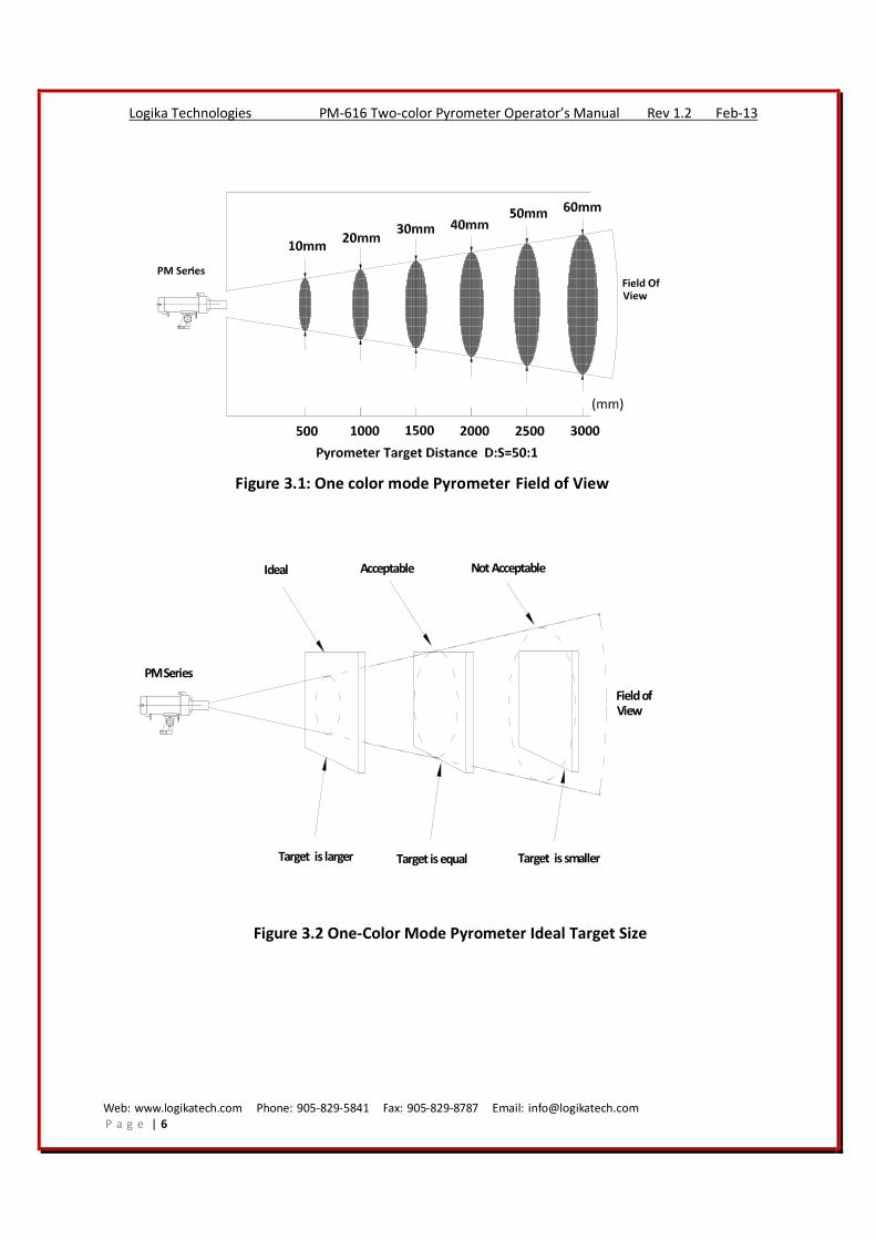
o One-color mode: target should be covered by the pyrometer’s field of view.
Check Figure 3.1 and Figure 3.2 for reference.
o Two-color mode: no restrictions to field of view.
For example:
If the target diameter is 20mm, pyrometer Displacement Coefficient is 50:1
(D/S=50:1).
In one-color mode, according to Figure3.1 and Figure3.2, the pyrometer has to be
installed less than 1 meter away from the target.
In two-color mode, it is not necessary for the target to be totally covered by the field
of view, the pyrometer can be installed more than 1 meter away from the target.
• Maximum ambient temperature for the pyrometer
o 50oC (122
oF) without water cooling
o 120oC (250
oF) with water cooling connected. See Figure 4.2
Web: www.logikatech.com Phone: 905-829-5841 Fax: 905-829-8787 Email: [email protected]
P a g e | 6
Logika Technologies PM-616 Two-color Pyrometer Operator’s Manual Rev 1.2 Feb-13
Figure 3.1: One color mode Pyrometer Field of View
Target is larger Target is equal Target is smaller
Ideal Acceptable Not Acceptable
PM Series
Field ofView
Figure 3.2 One-Color Mode Pyrometer Ideal Target Size
Web: www.logikatech.com Phone: 905-829-5841 Fax: 905-829-8787 Email: [email protected]
P a g e | 7
Logika Technologies PM-616 Two-color Pyrometer Operator’s Manual Rev 1.2 Feb-13
3.2 Pyrometer Mounting
Installation – PM-616 has an adjustable mounting foot which is secured using a M10 bolt.
Aiming - For standard pyrometer, use the aiming laser to properly align the pyrometer with
target.
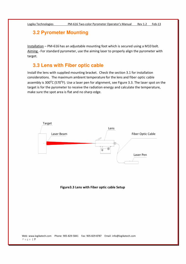
3.3 Lens with Fiber optic cable
Install the lens with supplied mounting bracket. Check the section 3.1 for installation
considerations. The maximum ambient temperature for the lens and fiber optic cable
assembly is 300oC (570
oF). Use a laser pen for alignment, see Figure 3.3. The laser spot on the
target is for the pyrometer to receive the radiation energy and calculate the temperature,
make sure the spot area is flat and no sharp edge.
Figure3.3 Lens with Fiber optic cable Setup
Web: www.logikatech.com Phone: 905-829-5841 Fax: 905-829-8787 Email: [email protected]
P a g e | 8
Logika Technologies PM-616 Two-color Pyrometer Operator’s Manual Rev 1.2 Feb-13
4 Utility Connections
4.1 Electrical Connections
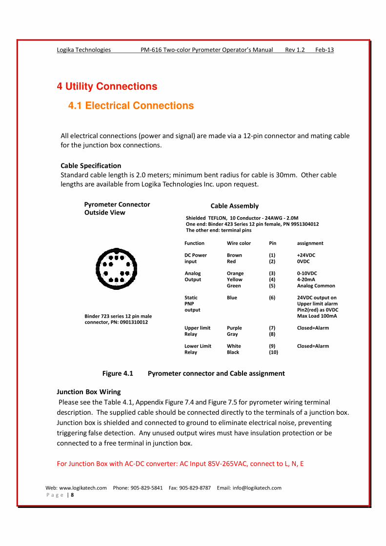
All electrical connections (power and signal) are made via a 12-pin connector and mating cable
for the junction box connections.
Cable Specification
Standard cable length is 2.0 meters; minimum bent radius for cable is 30mm. Other cable
lengths are available from Logika Technologies Inc. upon request.
Function Wire color Pin assignment
DC Power Brown (1) +24VDC
input Red (2) 0VDC
Analog Orange (3) 0-10VDC
Output Yellow (4) 4-20mA
Green (5) Analog Common
Static Blue (6) 24VDC output on
PNP Upper limit alarm
output Pin2(red) as 0VDC
Max Load 100mA
Upper limit Purple (7) Closed=Alarm
Relay Gray (8)
Lower Limit White (9) Closed=Alarm
Relay Black (10)
Pyrometer Connector
Outside ViewShielded TEFLON, 10 Conductor - 24AWG - 2.0M
One end: Binder 423 Series 12 pin female, PN 9951304012
The other end: terminal pins
Binder 723 series 12 pin maleconnector, PN: 0901310012
Cable Assembly
Figure 4.1 Pyrometer connector and Cable assignment
Junction Box Wiring
Please see the Table 4.1, Appendix Figure 7.4 and Figure 7.5 for pyrometer wiring terminal
description. The supplied cable should be connected directly to the terminals of a junction box.
Junction box is shielded and connected to ground to eliminate electrical noise, preventing
triggering false detection. Any unused output wires must have insulation protection or be
connected to a free terminal in junction box.
For Junction Box with AC-DC converter: AC Input 85V-265VAC, connect to L, N, E
Web: www.logikatech.com Phone: 905-829-5841 Fax: 905-829-8787 Email: [email protected]
P a g e | 9
Logika Technologies PM-616 Two-color Pyrometer Operator’s Manual Rev 1.2 Feb-13
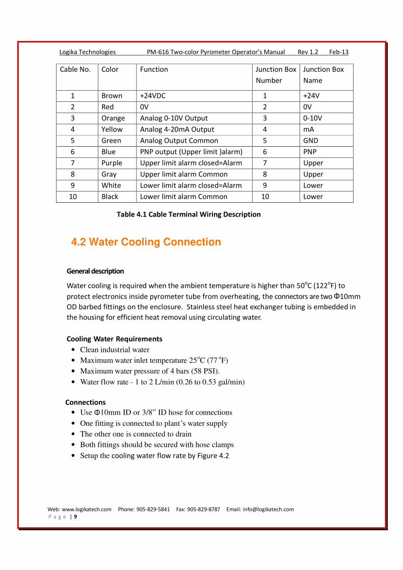
Cable No. Color Function Junction Box
Number
Junction Box
Name
1 Brown +24VDC 1 +24V
2 Red 0V 2 0V
3 Orange Analog 0-10V Output 3 0-10V
4 Yellow Analog 4-20mA Output 4 mA
5 Green Analog Output Common 5 GND
6 Blue PNP output (Upper limit )alarm) 6 PNP
7 Purple Upper limit alarm closed=Alarm 7 Upper
8 Gray Upper limit alarm Common 8 Upper
9 White Lower limit alarm closed=Alarm 9 Lower
10 Black Lower limit alarm Common 10 Lower
Table 4.1 Cable Terminal Wiring Description
4.2 Water Cooling Connection
General description
Water cooling is required when the ambient temperature is higher than 50oC (122
oF) to
protect electronics inside pyrometer tube from overheating, the connectors are two Φ10mm
OD barbed fittings on the enclosure. Stainless steel heat exchanger tubing is embedded in
the housing for efficient heat removal using circulating water.
Cooling Water Requirements
• Clean industrial water
• Maximum water inlet temperature 25oC (77
oF)
• Maximum water pressure of 4 bars (58 PSI).
• Water flow rate - 1 to 2 L/min (0.26 to 0.53 gal/min)
Connections
• Use Φ10mm ID or 3/8” ID hose for connections
• One fitting is connected to plant’s water supply
• The other one is connected to drain
• Both fittings should be secured with hose clamps
• Setup the cooling water flow rate by Figure 4.2

Web: www.logikatech.com Phone: 905-829-5841 Fax: 905-829-8787 Email: [email protected]
P a g e | 10
Logika Technologies PM-616 Two-color Pyrometer Operator’s Manual Rev 1.2 Feb-13
Am
bie
nt
Te
mp
era
atu
re
60
80
100
120
140
160
°C
Water0.3 0.5 1.0 1.5 2.0 L/M
8 °C
20 °C
25°C
Figure 4.2 Ambient Temperatures vs. Water Flow Rate
4.3 Purge Air Connection
Description- Compressed plant air can be used to protect the lens from dust and vapor. Purge
air cleans the lens, reduces maintenance times, and prolongs pyrometer’s life in where dusty
or corrosive vapor is present.
Purge Air Requirements
• Must be clean, dry instrument air no oil, dust and contaminants included. Poor air quality
will result in dirty lens and decrease pyrometer performance. If the quality of compressed
air can’t be guaranteed, it should not be connected to avoid lens contamination and affect
the pyrometer performance.
• Air filtration prior to the inlet fitting is recommended to improve the quality of purge air
• Air Pressure range from 50 to 200 g/cm2
(0.7 psi to 2.8 psi)
• Air Flow rate from 4 to 16 L/min (0.14 to 0.56 ft3/min)
Connection- Connect the plant air source to the purge air barbed fitting on the sensor’s lens
shroud with Φ10mm ID (or 3/8” ID) hose. Purge air flows out of the sensor shroud and
dissipates into the ambient environment.
Web: www.logikatech.com Phone: 905-829-5841 Fax: 905-829-8787 Email: [email protected]
P a g e | 11
Logika Technologies PM-616 Two-color Pyrometer Operator’s Manual Rev 1.2 Feb-13
5 Operation
5.1 Controls
PM-616 control panel is located at the rear of the pyrometer. The various functions are
described in greater detail below.
To reach control panel:
• Use M2.5 Allen key to remove the back cover from unit
• Unthread the glass cover on the pyrometer body by turning it counterclockwise
!!! When operating on the control panel, please note:
o The pyrometer tube may slide out of cooling tube if angled downwards. Keep unit level
when disassembling for menu adjustment.
o The pyrometer tube is sealed during manufacturing to retain accuracy and quality.
Warranty is void if pyrometer tube is dismantled for any reason.
5.2 Set Menu Functions and Programming
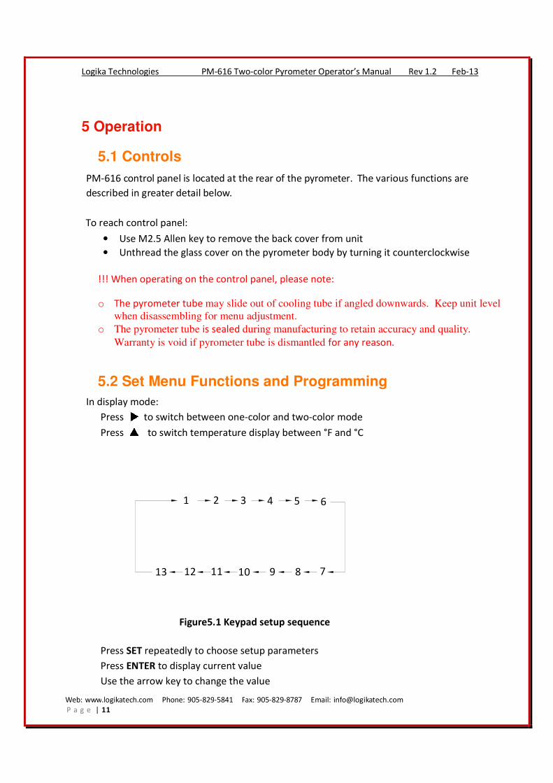
In display mode:
Press to switch between one-color and two-color mode
Press ▲ to switch temperature display between °F and °C
1 2 3 4 5 6
78910111213
Figure5.1 Keypad setup sequence
Press SET repeatedly to choose setup parameters
Press ENTER to display current value
Use the arrow key to change the value
Web: www.logikatech.com Phone: 905-829-5841 Fax: 905-829-8787 Email: [email protected]
P a g e | 12
Logika Technologies PM-616 Two-color Pyrometer Operator’s Manual Rev 1.2 Feb-13
Press ENTER again to save the new value and EXIT setup
Set Menu 1- Emissivity/Slope Adjustment
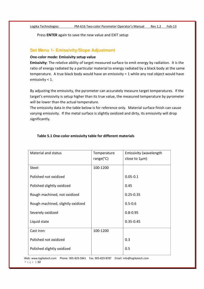
One-color mode: Emissivity setup value
Emissivity: The relative ability of target measured surface to emit energy by radiation. It is the
ratio of energy radiated by a particular material to energy radiated by a black body at the same
temperature. A true black body would have an emissivity = 1 while any real object would have
emissivity < 1.
By adjusting the emissivity, the pyrometer can accurately measure target temperatures. If the
target’s emissivity is setup higher than its true value, the measured temperature by pyrometer
will be lower than the actual temperature.
The emissivity data in the table below is for reference only. Material surface finish can cause
varying emissivity. If the metal surface is slightly oxidized and dirty, its emissivity will drop
significantly.
Table 5.1 One-color emissivity table for different materials
Material and status Temperature
range(°C)
Emissivity (wavelength
close to 1μm)
Steel:
Polished not oxidized
Polished slightly oxidized
Rough machined, not oxidized
Rough machined, slightly oxidized
Severely oxidized
Liquid state
100-1200
0.05-0.1
0.45
0.25-0.35
0.5-0.6
0.8-0.95
0.35-0.45
Cast iron:
Polished not oxidized
Polished slightly oxidized
100-1200
0.3
0.5
Web: www.logikatech.com Phone: 905-829-5841 Fax: 905-829-8787 Email: [email protected]
P a g e | 13
Logika Technologies PM-616 Two-color Pyrometer Operator’s Manual Rev 1.2 Feb-13
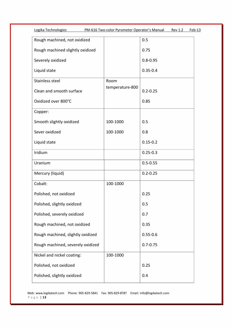
Rough machined, not oxidized
Rough machined slightly oxidized
Severely oxidized
Liquid state
0.5
0.75
0.8-0.95
0.35-0.4
Stainless steel
Clean and smooth surface
Oxidized over 800°C
Room
temperature-800
0.2-0.25
0.85
Copper:
Smooth slightly oxidized
Sever oxidized
Liquid state
100-1000
100-1000
0.5
0.8
0.15-0.2
Iridium 0.25-0.3
Uranium 0.5-0.55
Mercury (liquid) 0.2-0.25
Cobalt:
Polished, not oxidized
Polished, slightly oxidized
Polished, severely oxidized
Rough machined, not oxidized
Rough machined, slightly oxidized
Rough machined, severely oxidized
100-1000
0.25
0.5
0.7
0.35
0.55-0.6
0.7-0.75
Nickel and nickel coating:
Polished, not oxidized
Polished, slightly oxidized
100-1000
0.25
0.4

Web: www.logikatech.com Phone: 905-829-5841 Fax: 905-829-8787 Email: [email protected]
P a g e | 14
Logika Technologies PM-616 Two-color Pyrometer Operator’s Manual Rev 1.2 Feb-13
Polished, severely oxidized
Rough machined, not oxidized
Rough machined, slightly oxidized
Rough machined, severely oxidized
0.8-0.9
0.35
0.5
0.8-0.9
Black oxide nickel 500-1000 0.8-0.9
Bismuth 0.34
Silver and silver coating:
Rough machined, not oxidized
Rough machined, slightly oxidized
100-900
0.1-0.25
0.15-0.35
Tungsten
Ribbon, polished, not oxidized
(tungsten lamp)
1500 0.3-0.39
0.3-0.37
0.3-0.36
Magnesium : polished, not oxidized 0.1-0.2
Platinum:
Polished, not oxidized
Polished, slightly oxidized
Polished, severely oxidized
Rough machined, not oxidized
Rough machined, slightly oxidized
Rough machined, severely oxidized
Platinum black
50-1000
0.25
0.3
0.4
0.3
0.4
0.4-0.5
0.95
Tantalum:
Polished, not oxidized
Polished, slightly oxidized
100-1000
0.2
0.45
Web: www.logikatech.com Phone: 905-829-5841 Fax: 905-829-8787 Email: [email protected]
P a g e | 15
Logika Technologies PM-616 Two-color Pyrometer Operator’s Manual Rev 1.2 Feb-13
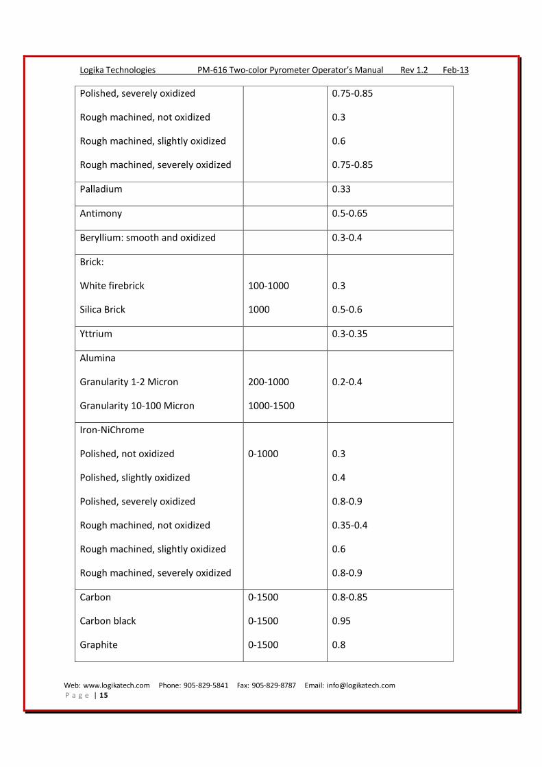
Polished, severely oxidized
Rough machined, not oxidized
Rough machined, slightly oxidized
Rough machined, severely oxidized
0.75-0.85
0.3
0.6
0.75-0.85
Palladium 0.33
Antimony 0.5-0.65
Beryllium: smooth and oxidized 0.3-0.4
Brick:
White firebrick
Silica Brick
100-1000
1000
0.3
0.5-0.6
Yttrium 0.3-0.35
Alumina
Granularity 1-2 Micron
Granularity 10-100 Micron
200-1000
1000-1500
0.2-0.4
Iron-NiChrome
Polished, not oxidized
Polished, slightly oxidized
Polished, severely oxidized
Rough machined, not oxidized
Rough machined, slightly oxidized
Rough machined, severely oxidized
0-1000
0.3
0.4
0.8-0.9
0.35-0.4
0.6
0.8-0.9
Carbon
Carbon black
Graphite
0-1500
0-1500
0-1500
0.8-0.85
0.95
0.8

Web: www.logikatech.com Phone: 905-829-5841 Fax: 905-829-8787 Email: [email protected]
P a g e | 16
Logika Technologies PM-616 Two-color Pyrometer Operator’s Manual Rev 1.2 Feb-13
Procedure to adjust the emissivity in one-color mode:
1. Set the pyrometer to work in one-color mode (Mode LED off).
2. Determine actual target temperature with a contact RTD, thermocouple or other
appropriate instrument.
3. Press SET button until the display shows “1-“(flashing), then press ENTER to adjust
the emissivity.
4. Use the “up” and “right” arrow buttons to adjust the value.
5. The emissivity adjustment range is from 0.10 to 1.00; in 0.01 increments. For
0.01↑, results in 1.0°C ↓, factory default value is 0.95.
6. Press ENTER to save the adjustment and return to the temperature display mode.
Two-color mode: Temperature Slope Adjustment (Calibration)
Temperature slope is a coefficient to compensate for the two wavelengths emissivity
difference.
Note: The listed ratios are approximate values and can change with alloy surface condition and
oxidization.
For these oxide metals, the temperature slope setup value is 1.000
Cobalt Nickel Iron Stainless steel Steel
For these metals, the temperature slope value is 1.030
Cobalt Iron Stainless Steel
Rhodium Tungsten Molybdenum
Platinum Steel Nickel
Tantalum Cast Iron
Slope adjustment allows the user to refine the accuracy of the pyrometer for specific
applications. This feature can be used to calibrate the pyrometer.
1. Use a reliable thermometer to measure the surface temperature of the target. If
temperature readings vary in different measured areas, use the average reading.
2. Set the pyrometer to work in two-color mode (Mode LED ON)
3. Press SET button until the display shows “1-“(flashing), then press ENTER to adjust the
temperature slope.
4. Use the “up” and “right” arrow buttons to adjust the value.
5. The temperature slope adjustment range is 0.850 to 1.150 in 0.001 increments. For 0.001↑,
Web: www.logikatech.com Phone: 905-829-5841 Fax: 905-829-8787 Email: [email protected]
P a g e | 17
Logika Technologies PM-616 Two-color Pyrometer Operator’s Manual Rev 1.2 Feb-13
results in 1.4°C ↓. Factory default setup value is 1.000.
6. Press ENTER to accept the slope adjustment and return to the temperature display mode.
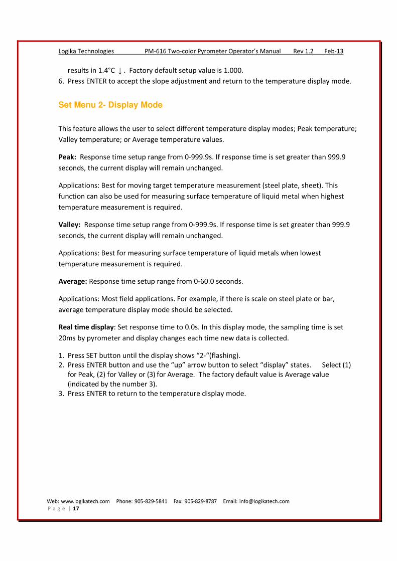
Set Menu 2- Display Mode
This feature allows the user to select different temperature display modes; Peak temperature;
Valley temperature; or Average temperature values.
Peak: Response time setup range from 0-999.9s. If response time is set greater than 999.9
seconds, the current display will remain unchanged.
Applications: Best for moving target temperature measurement (steel plate, sheet). This
function can also be used for measuring surface temperature of liquid metal when highest
temperature measurement is required.
Valley: Response time setup range from 0-999.9s. If response time is set greater than 999.9
seconds, the current display will remain unchanged.
Applications: Best for measuring surface temperature of liquid metals when lowest
temperature measurement is required.
Average: Response time setup range from 0-60.0 seconds.
Applications: Most field applications. For example, if there is scale on steel plate or bar,
average temperature display mode should be selected.
Real time display: Set response time to 0.0s. In this display mode, the sampling time is set
20ms by pyrometer and display changes each time new data is collected.
1. Press SET button until the display shows “2-“(flashing).
2. Press ENTER button and use the “up” arrow button to select “display” states. Select (1)
for Peak, (2) for Valley or (3) for Average. The factory default value is Average value
(indicated by the number 3).
3. Press ENTER to return to the temperature display mode.
Web: www.logikatech.com Phone: 905-829-5841 Fax: 905-829-8787 Email: [email protected]
P a g e | 18
Logika Technologies PM-616 Two-color Pyrometer Operator’s Manual Rev 1.2 Feb-13
Temperature
TimeΔt 2Δt 3Δt 4Δt0
Peak Display
Actual Temperature
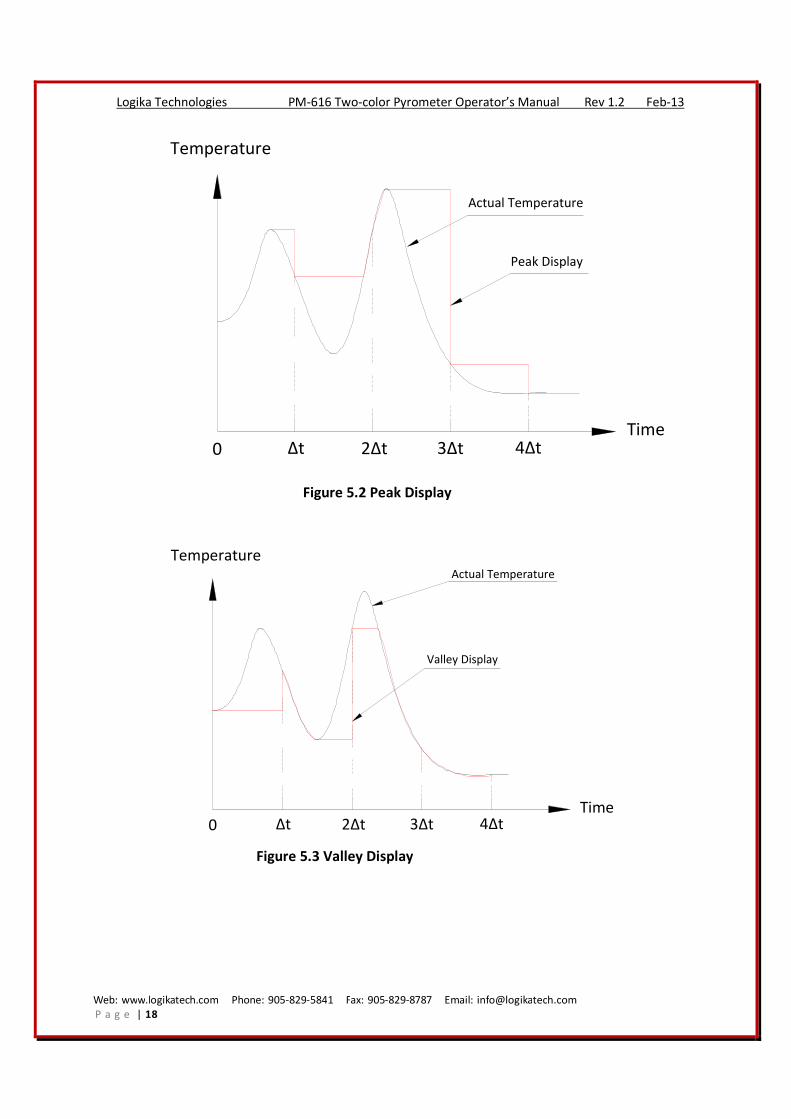
Figure 5.2 Peak Display
Temperature
TimeΔt 2Δt 3Δt 4Δt0
Valley Display
Actual Temperature
Figure 5.3 Valley Display
Web: www.logikatech.com Phone: 905-829-5841 Fax: 905-829-8787 Email: [email protected]
P a g e | 19
Logika Technologies PM-616 Two-color Pyrometer Operator’s Manual Rev 1.2 Feb-13
Temperature
TimeΔt 2Δt 3Δt 4Δt0
Average display
Actual temperature
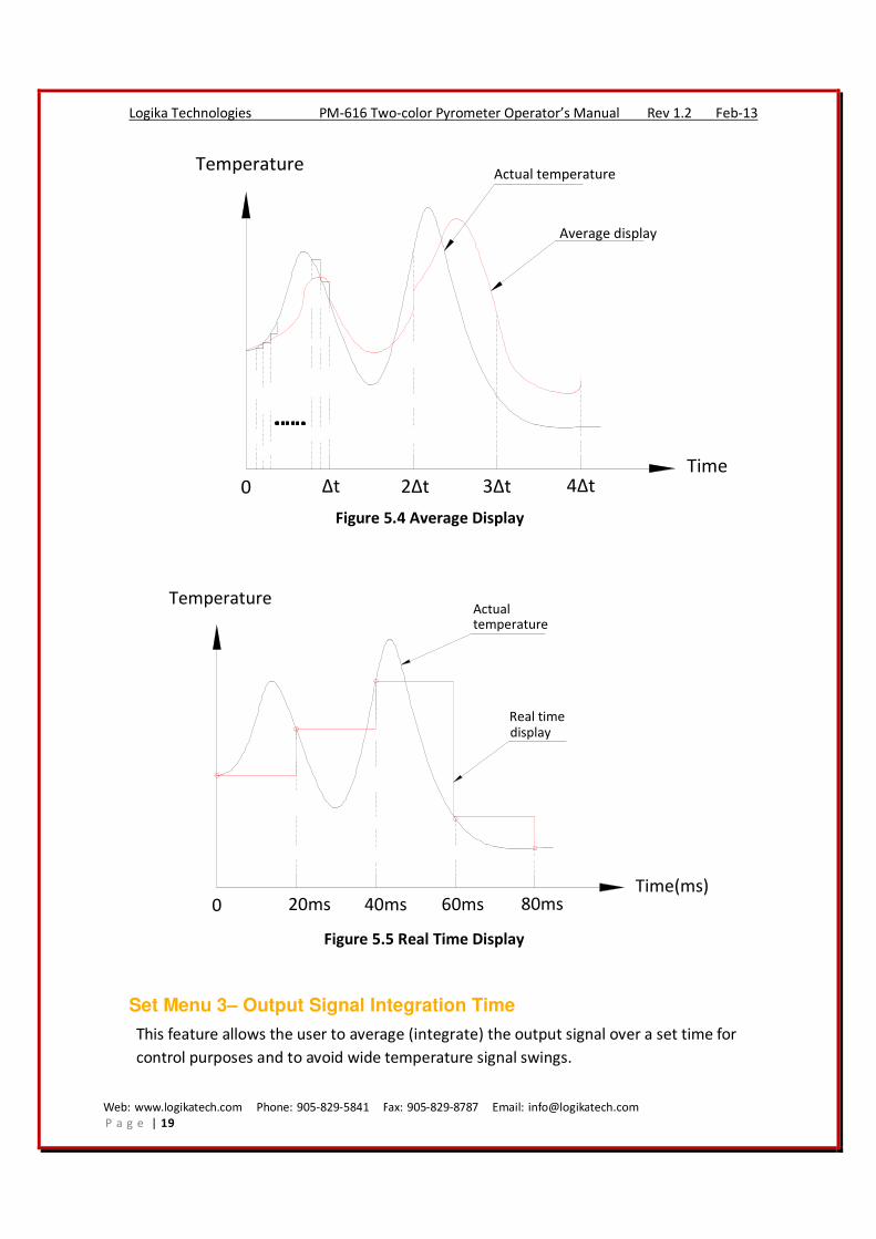
Figure 5.4 Average Display
Temperature
Time(ms)20ms 40ms 60ms 80ms0
Real timedisplay
Actualtemperature
Figure 5.5 Real Time Display
Set Menu 3– Output Signal Integration Time
This feature allows the user to average (integrate) the output signal over a set time for
control purposes and to avoid wide temperature signal swings.
Web: www.logikatech.com Phone: 905-829-5841 Fax: 905-829-8787 Email: [email protected]
P a g e | 20
Logika Technologies PM-616 Two-color Pyrometer Operator’s Manual Rev 1.2 Feb-13
Press SET until the display shows “3“ (flashing), then press ENTER to adjust the signal
integration time. Use the “up” and “right” arrow buttons to adjust the integration time.
The time adjustment range is 0 to 999 seconds. The factory default setting is 0 seconds.
Press ENTER to return to the temperature display mode.
For peak and valley temperature detection, the time adjustment range is 0-999s. For
average temperature detection, the time adjustment range is 0-60s.
Set Menu 4-, 5-, 6- Process Alarm Settings
Use these menus to set the upper and lower alarms and the alarm deadband (to prevent
alarm relay contacts “chatter”, this is the temperature range in which the alarm turns off
after being triggered).
Menu “-4”: Upper Limit Alarm, default 1600°C
Menu “-5”: Lower Limit Alarm, default 600°C
Menu “-6”: Alarm Deadband coefficient, default 0.001
If temperature is lower than 600°C, lower alarm relay is triggered, “Lower” alarm LED
indicator turns ON
If temperature is higher than 1600°C, upper alarm relay is triggered. PNP output high
(24VDC) “upper” alarm LED indicator turns ON.
Note: Lower alarm may be set higher than the upper alarm
Deadband coefficient range 0 - 0.500
Lower alarm deadband= ±deadband coefficient*lower alarm setting
Upper alarm deadband= ±deadband coefficient*upper alarm setting
1. Use the “up” and “right” arrow buttons to adjust the alarm settings. Alarm settings are °C
(or °F).
2. Press ENTER to return to the temperature display mode.
Set Menu 7-, 8- Current/Voltage Analog Output Span Settings
Set the linear temperature span to correspond with the current or voltage output of the
pyrometer.
Menu 7- : Lower Temperature for the output span, default 600°C
Menu 8- : Upper Temperature for the output span, default 1600°C
1. Use the “up” and “right” arrow buttons to adjust the span settings
2. Press ENTER to return to the temperature display mode.
Web: www.logikatech.com Phone: 905-829-5841 Fax: 905-829-8787 Email: [email protected]
P a g e | 21
Logika Technologies PM-616 Two-color Pyrometer Operator’s Manual Rev 1.2 Feb-13
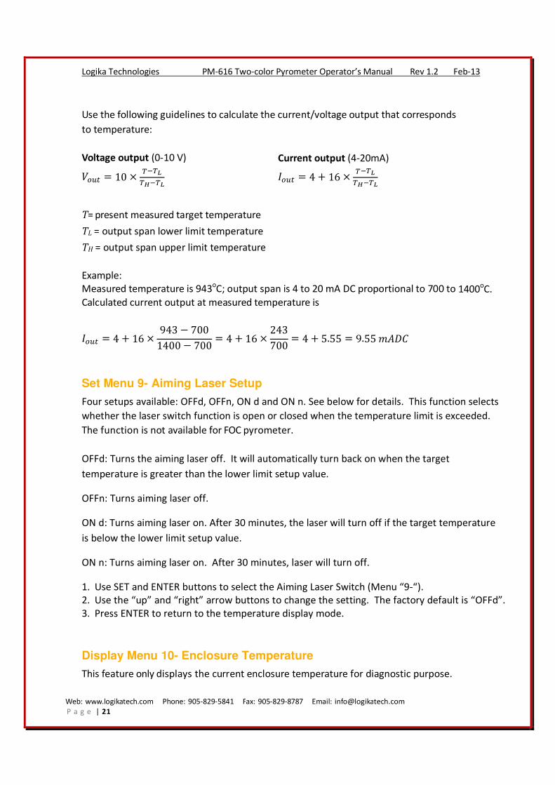
Use the following guidelines to calculate the current/voltage output that corresponds
to temperature:
Voltage output (0-10 V) Current output (4-20mA)
���� � 10 �� ��
�� �� ���� � 4 � 16 �
� ��
�� ��
T= present measured target temperature
TL = output span lower limit temperature
TH = output span upper limit temperature
Example:
Measured temperature is 943oC; output span is 4 to 20 mA DC proportional to 700 to 1400
oC.
Calculated current output at measured temperature is
���� � 4 � 16 �943 � 700
1400 � 700� 4 � 16 �
243
700� 4 � 5.55 � 9.55 ����
Set Menu 9- Aiming Laser Setup
Four setups available: OFFd, OFFn, ON d and ON n. See below for details. This function selects
whether the laser switch function is open or closed when the temperature limit is exceeded.
The function is not available for FOC pyrometer.
OFFd: Turns the aiming laser off. It will automatically turn back on when the target
temperature is greater than the lower limit setup value.
OFFn: Turns aiming laser off.
ON d: Turns aiming laser on. After 30 minutes, the laser will turn off if the target temperature
is below the lower limit setup value.
ON n: Turns aiming laser on. After 30 minutes, laser will turn off.
1. Use SET and ENTER buttons to select the Aiming Laser Switch (Menu “9-“).
2. Use the “up” and “right” arrow buttons to change the setting. The factory default is “OFFd”.
3. Press ENTER to return to the temperature display mode.
Display Menu 10- Enclosure Temperature
This feature only displays the current enclosure temperature for diagnostic purpose.
Web: www.logikatech.com Phone: 905-829-5841 Fax: 905-829-8787 Email: [email protected]
P a g e | 22
Logika Technologies PM-616 Two-color Pyrometer Operator’s Manual Rev 1.2 Feb-13
If the enclosure temperature is higher than 70 oC, the display shows “EEE1”.
If the enclosure temperature is lower than -10 oC, the display shows “EEE2”.
Either of these conditions exists, steps must be taken to adjust the ambient temperature.
Display Menu 11- Two Color Ratio
This function only displays the ratio of the current two wavelength signals for service
diagnostic purposes.
Set Menu 12- Zero Compensation Gain
This feature is used to adjust the detector gain to compensate for targets with a starting
temperature below the specified measurement limits of the Logika PM-616 pyrometer.
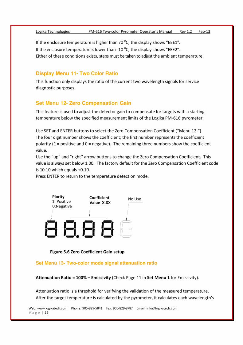
Use SET and ENTER buttons to select the Zero Compensation Coefficient (“Menu 12-“)
The four digit number shows the coefficient; the first number represents the coefficient
polarity (1 = positive and 0 = negative). The remaining three numbers show the coefficient
value.
Use the “up” and “right” arrow buttons to change the Zero Compensation Coefficient. This
value is always set below 1.00. The factory default for the Zero Compensation Coefficient code
is 10.10 which equals +0.10.
Press ENTER to return to the temperature detection mode.
No UsePlority1: Positive0:Negative
Coefficient
Value X.XX
Figure 5.6 Zero Coefficient Gain setup
Set Menu 13- Two-color mode signal attenuation ratio
Attenuation Ratio = 100% – Emissivity (Check Page 11 in Set Menu 1 for Emissivity).
Attenuation ratio is a threshold for verifying the validation of the measured temperature.
After the target temperature is calculated by the pyrometer, it calculates each wavelength’s
Web: www.logikatech.com Phone: 905-829-5841 Fax: 905-829-8787 Email: [email protected]
P a g e | 23
Logika Technologies PM-616 Two-color Pyrometer Operator’s Manual Rev 1.2 Feb-13
emissivity at this temperature. For each wavelength, the attenuation ratio (100% – Emissivity
value) should not be less than the set value. If either one is higher than the set value, the
pyrometer displays the lower limit temperature.
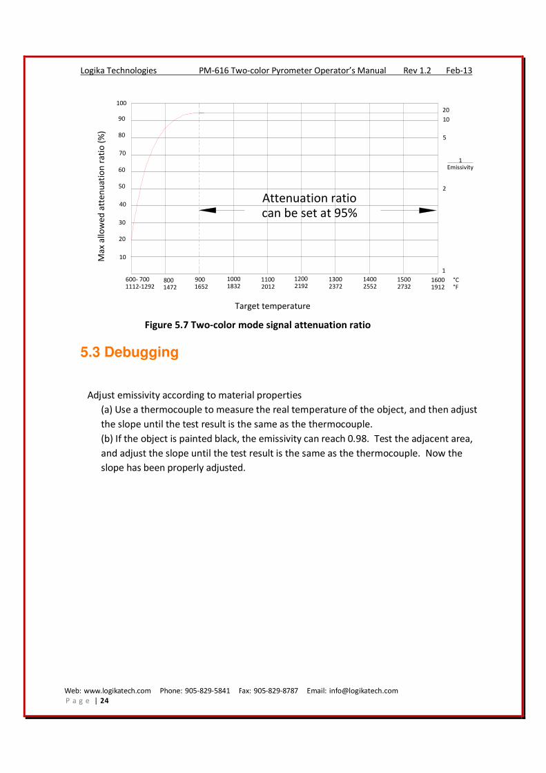
This function is only used in two-color mode. The setup range is 20%-100% and the default
setup value is 95%. If the attenuation ratio is set greater than 95%, this function will shut
down; and again, the lower limit temperature will be displayed. For example, if the pyrometer
is used to detect the temperature of tungsten filament of a light bar, usually the temperature
is higher than 1500°C (2732°F). The tungsten filament (target) diameter is very small at 2mm,
so the emissivity would be very low. According to Figure 5.6, if the temperature is greater
than 900°C and target size is 2mm, the attenuation ratio should be set to 95%. This means
that as long as the emissivity value for each wavelength signal is not less than 5%, the
calculated temperature is valid. In this case, the two-color mode, can still accurately calculate
the temperature. In single color mode, it would be very hard to get an accurate target
temperature in this situation.
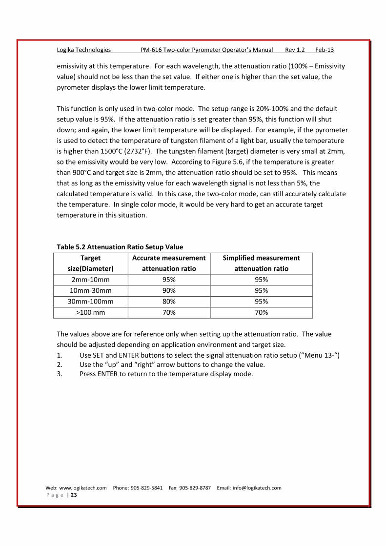
Table 5.2 Attenuation Ratio Setup Value
Target
size(Diameter)
Accurate measurement
attenuation ratio
Simplified measurement
attenuation ratio
2mm-10mm 95% 95%
10mm-30mm 90% 95%
30mm-100mm 80% 95%
>100 mm 70% 70%
The values above are for reference only when setting up the attenuation ratio. The value
should be adjusted depending on application environment and target size.
1. Use SET and ENTER buttons to select the signal attenuation ratio setup (“Menu 13-“)
2. Use the “up” and “right” arrow buttons to change the value.
3. Press ENTER to return to the temperature display mode.
Web: www.logikatech.com Phone: 905-829-5841 Fax: 905-829-8787 Email: [email protected]
P a g e | 24
Logika Technologies PM-616 Two-color Pyrometer Operator’s Manual Rev 1.2 Feb-13
600- 7001112-1292
8001472
9001652
10001832
11002012
12002192
13002372
14002552
15002732
16001912
10
20
30
40
50
60
70
80
90
100
1
2
5
10
20
Attenuation ratiocan be set at 95%
1Emissivity
Target temperature
Ma
x a
llo
we
d a
tte
nu
ati
on
ra
tio
(%
)
°C°F
Figure 5.7 Two-color mode signal attenuation ratio
5.3 Debugging
Adjust emissivity according to material properties
(a) Use a thermocouple to measure the real temperature of the object, and then adjust
the slope until the test result is the same as the thermocouple.
(b) If the object is painted black, the emissivity can reach 0.98. Test the adjacent area,
and adjust the slope until the test result is the same as the thermocouple. Now the
slope has been properly adjusted.

Web: www.logikatech.com Phone: 905-829-5841 Fax: 905-829-8787 Email: [email protected]
P a g e | 25
Logika Technologies PM-616 Two-color Pyrometer Operator’s Manual Rev 1.2 Feb-13
Table 5.2 PM-616 Keypad Operation
Function Description Default Key
SET Setup Parameters Display parameters from 1- to 13- each time button is pressed.
Press ENTER to Exit N/A SETUP
1- Slope/Emissivity
Adjustment
Single Color: Emissivity Rate, Range 0.10-1.00
Two Color: Temperature Slope: 0.850-1.150
0.95
1.000
2- Display/Sample
Mode
1 = Peak 2 = Valley 3 = Average 3
3- Response Time 0.0-999.9s adjustable. 0s=20ms, internal setup value, real time
display 0.5
4- Upper Limit Alarm Modify the Upper limit alarm temperature value 1600°C
5- Lower Limit Alarm Modify the Lower limit alarm temperature value 600°C
6- Alarm Deadband Modify alarm deadband value 0.001(0.1%)
7- Analog Output
Span Lower Limit
Temperature corresponds to linear analog current/voltage
output span lower value 600°C
8- Analog Output
Span Upper Limit
Temperature corresponds to linear analog current/voltage
output span upper value 1600°C
9- Aiming Laser Standard PM only, not for fiber optic PM. 4 setups available:
OFFd, OFFn, ONd, ONn. See setup menu 9- for details. OFFd
10- Enclosure
Temperature
Setup constant at 40°C. If display is higher than 50°C, the
pyrometer should be cooled down N/A
Display
only
11- Two Color Signal
Ratio
Only used for pyrometer diagnostic purposes. In two color
mode, select 3(average) in setup 3-, the display value is the
ratio of the two wavelength signals
N/A Display
only
12- Zero
compensation
gain
Adjusts the pyrometer gain to compensate for targets with a
starting temperature below specified measurement limits. First
digit on left 1=positive, 0=negative. The remaining 3 numbers
are the coefficient value. The value should always be set below
0.30
10.10 (+0.1)
13- Two Color Signal
Attenuation Ratio
Only used in two color mode. If setup value is greater than
95%, this function is off. See setup menu 13- for details. 95%
Web: www.logikatech.com Phone: 905-829-5841 Fax: 905-829-8787 Email: [email protected]
P a g e | 26
Logika Technologies PM-616 Two-color Pyrometer Operator’s Manual Rev 1.2 Feb-13
6 Maintenance
6.1 Regular Maintenance
Regular attention to the following will ensure accurate and prolonged operation of the
pyrometer:
Lens Cleaning - Routinely check the lens glass for dust or oil residue. If necessary, clean glass
with alcohol and lens paper or soft cloth.
Calibration - Occasional calibration using the temperature slope adjustment (see “Set Menu 1“)
will ensure that maximum accuracy is maintained.
6.2 Instrument Return
Contact us at 1-888-856-4452 (1-888-8LOGIKA) with the Serial Number of your pyrometer
before you return our product. If the problem cannot be resolved by telephone or email, we
will provide you with a return authorization number.
Please return to: Logika Technologies Inc.
2-2857 Sherwood Heights Drive,
Oakville, ON, L6J 7J9
Canada
Do not return the pyrometer without a return authorization number. If the product is out of
warranty, we will provide a repair estimate and then complete the repairs upon your approval.
Web: www.logikatech.com Phone: 905-829-5841 Fax: 905-829-8787 Email: [email protected]
P a g e | 27
Logika Technologies PM-616 Two-color Pyrometer Operator’s Manual Rev 1.2 Feb-13
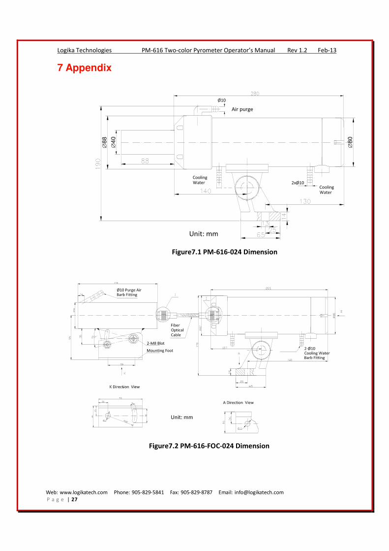
7 Appendix
Figure7.1 PM-616-024 Dimension
Figure7.2 PM-616-FOC-024 Dimension
Web: www.logikatech.com Phone: 905-829-5841 Fax: 905-829-8787 Email: [email protected]
P a g e | 28
Logika Technologies PM-616 Two-color Pyrometer Operator’s Manual Rev 1.2 Feb-13
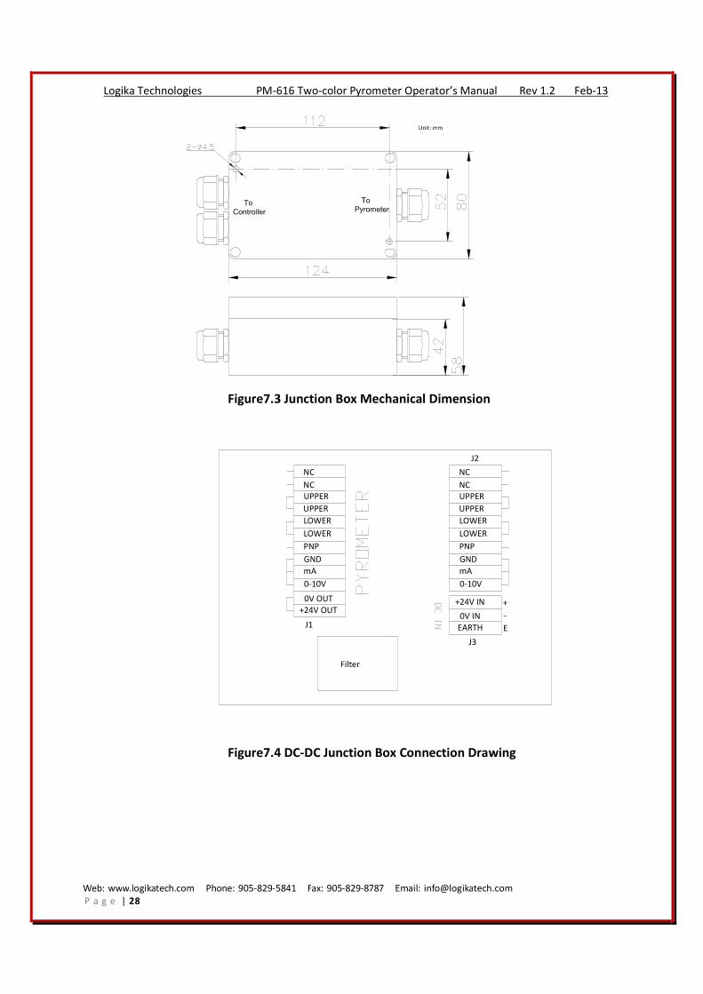
Figure7.3 Junction Box Mechanical Dimension
+24V OUT
0V OUT
0-10V
mA
GND
PNP
LOWER
LOWER
UPPER
UPPER
J1
J2
J3
Filter
NC
NC
0-10V
mA
GND
PNP
LOWER
LOWER
UPPER
UPPER
NC
NC
+
-
E
+24V IN
EARTH
0V IN
Figure7.4 DC-DC Junction Box Connection Drawing
Web: www.logikatech.com Phone: 905-829-5841 Fax: 905-829-8787 Email: [email protected]
P a g e | 29
Logika Technologies PM-616 Two-color Pyrometer Operator’s Manual Rev 1.2 Feb-13
J3
L
EARTH
N
J1
+24V OUT
0V OUT
0-10V
mA
GND
PNP
LOWER
LOWER
UPPER
UPPER
NC
NC
J2
+24V OUT
0V OUT
0-10V
mA
GND
PNP
LOWER
LOWER
UPPER
UPPER
NC
NC
AC-DCConverter
DC Filter
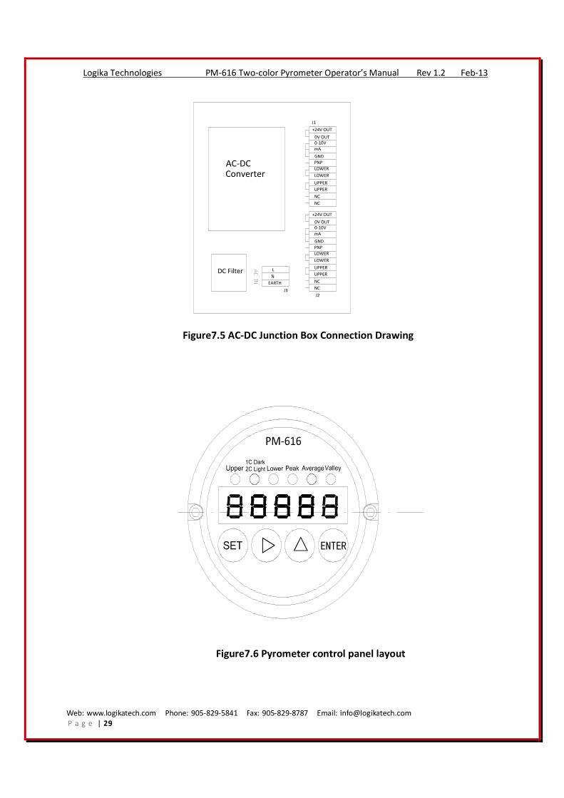
Figure7.5 AC-DC Junction Box Connection Drawing
Figure7.6 Pyrometer control panel layout
Web: www.logikatech.com Phone: 905-829-5841 Fax: 905-829-8787 Email: [email protected]
P a g e | 30
Logika Technologies PM-616 Two-color Pyrometer Operator’s Manual Rev 1.2 Feb-13
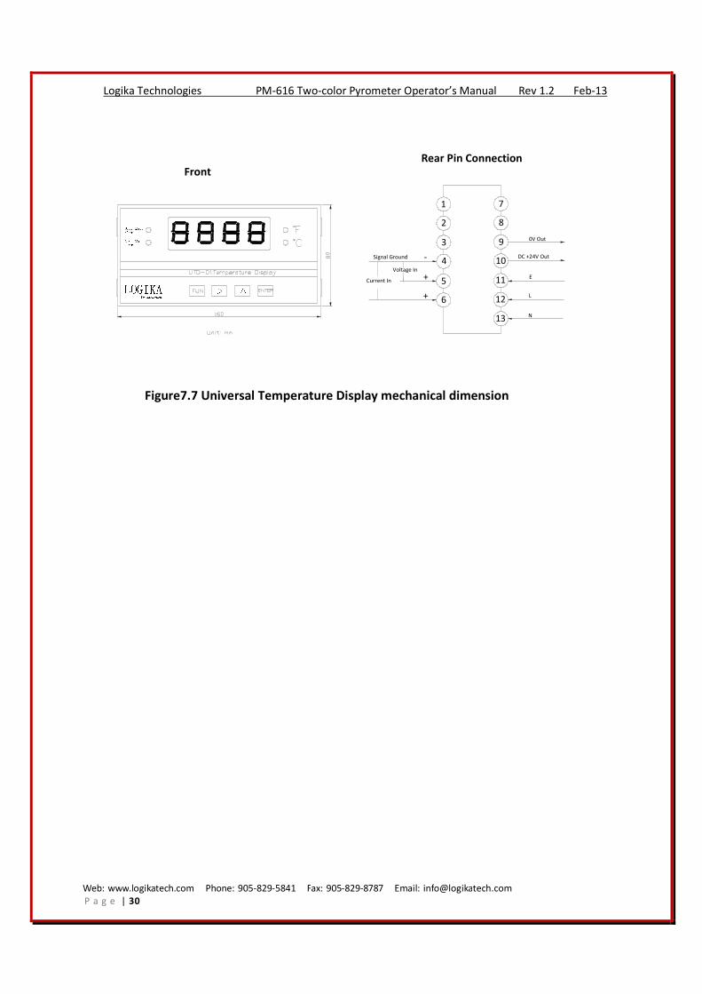
LOGIKAUpper LimitAlarmLower LimitAlarm △ △TechnologiesFront
Rear Pin Connection
1
2
3
4
5
6
7
8
9
10
11
12
13
Voltage In
Current In +
-
+
Signal Ground
L
E
N
DC +24V Out
0V Out
Figure7.7 Universal Temperature Display mechanical dimension