model predictive climate control of connected and ... · in future connected and automated vehicles...
TRANSCRIPT

Model Predictive Climate Control of Connected and AutomatedVehicles for Improved Energy Efficiency
Hao Wang1, Ilya Kolmanovsky2, Mohammad Reza Amini1, and Jing Sun1
Abstract— This paper considers an application of modelpredictive control to automotive air conditioning (A/C) systemin future connected and automated vehicles (CAVs) with batteryelectric or hybrid electric powertrains. A control-orientedprediction model for A/C system is proposed, identified, andvalidated against a higher fidelity simulation model (CoolSim).Based on the developed prediction model, a nonlinear modelpredictive control (NMPC) problem is formulated and solvedonline to minimize the energy consumption of the A/C system.Simulation results illustrate the desirable characteristics of theproposed NMPC solution such as being able to enforce physicalconstraints of the A/C system and maintain cabin temperaturewithin a specified range. Moreover, it is shown that by utilizingthe vehicle speed preview and through coordinated adjustmentof the cabin temperature constraints, energy efficiency improve-ments of up to 9% can be achieved.
I. INTRODUCTION
The information available through V2V, V2I, and ad-vanced sensors in connected and automated vehicles (CAVs)provides increased situational awareness, preview of trafficconditions, and can facilitate intelligent decision-making inpowertrain and vehicle control applications. Of particularinterest is the improvement in fuel economy and/or thereduction in energy consumption which can be achieved inCAVs.
Thermal loads, such as those used for heating, ventilation,& air conditioning (HVAC) of the passenger compartment,and for the electric motor and battery package cooling,represent the most significant auxiliary loads for light-dutyvehicles [1]. It has been estimated that, in the United States,about 7 billion gallons of fuel is consumed per year justto power the air conditioning (A/C) system for light-dutyvehicles [1]. A study performed at Argonne National Labshowed a 53.7% reduction in vehicle driving range due to airconditioning and 59.3% reduction in vehicle driving rangedue to heating for Ford Focus EV, tested over the UrbanDynamometer Driving Schedule (UDDS) [2]. Similarly, asignificant reduction of driving range was also reported forNissan Leaf [2] and in a recent work by National RenewableEnergy Lab [3].
Many of the CAV related research activities, such aseco-driving and platooning, have focused on reducing trac-
*This project is supported by the United States Department of Energy(DOE), ARPA-E NEXTCAR program (Award No.: de-ar0000797).
1Hao Wang, Mohammad Reza Amini, and Jing Sun are with the Depart-ment of Naval Architecture & Marine Engineering, University of Michi-gan, Ann Arbor, MI 48109 USA. Emails: {autowang, jingsun,mamini}@umich.edu
2Ilya Kolmanovsky is with the Department of Aerospace Engineer-ing, University of Michigan, Ann Arbor, MI 48109 USA. Email:[email protected]
tion power related losses, whereas the impact of thermalmanagement has not been fully explored. Previous researchhas addressed the energy management of the A/C systemfor vehicles with traditional internal combustion engines(ICEs) [4] [5], where the A/C compressor is belt-drivenby the ICE. The energy management problem consideredin these references was solved by a dynamic programming(DP) algorithm. However, as vehicle power sources are be-coming more electrically dominant, their energy managementrequires different strategies than those used for vehicleswith traditional ICEs. Recognizing the pressing need tointegrate advanced thermal management into overall vehicleenergy optimization, a predictive climate control strategyis developed in this paper to reduce A/C system energyconsumption.
The ability to enforce constraints and account for fu-ture operating conditions in rendering control decisions areamong the key appealing features of MPC. For HVAC controlin buildings, predictive temperature management strategieshave been studied extensively and showed substantial energysaving potentials (see [6], [7], and [8]). Similar problems forvehicles have been addressed much less and they have severaldistinct aspects compared to temperature control in buildings,including faster temperature dynamics, complicated passen-ger comfort requirements, vehicle speed dependence, and theneed for solution with low computational footprint suitablefor onboard implementation.
In this paper, we are focusing on hybrid and electricvehicle applications, where the compressor of the A/C systemis driven by an electric motor and draws power directlyfrom an onboard high-voltage battery pack. We note thatcomprehensive modeling of such an A/C system based on thevapor compression cycle is very involved [9]. Our subsequentdevelopments exploit a high-fidelity simulation model from[10], and a simplified control-oriented model which is usedfor prediction and validated against our high fidelity model.A model predictive controller for the A/C system is thendeveloped that uses the control-oriented model for predictionand minimizes energy consumption. We also show, througha case study, that a preview of future vehicle speed profilein CAVs can be exploited to further decrease A/C systemenergy consumption.
The rest of the paper is organized as follows. Details ofthe high-fidelity simulation model and the development ofthe simplified prediction model are presented in Section II.Our design of the model predictive climate control schemeis described in Section III. Section IV presents simulationresults and demonstrates energy efficiency improvements.
arX
iv:1
803.
0072
0v1
[cs
.SY
] 2
Mar
201
8

The conclusions are presented in Section V.
II. PREDICTION MODEL DEVELOPMENT
A. CoolSim High Fidelity Model and Speed Sensitivity Anal-ysis
A high fidelity simulation model of the passenger car A/Csystem has been established based on CoolSim which is anopen-source modeling environment available from the Na-tional Renewable Energy Lab (NREL), see [11]. Fig. 1 showsthe schematics of the Simulink® model of the A/C systemin CoolSim. There are four major subcomponents within thismodel: (i) the boundary condition block, which provides thespeed profiles and ambient conditions such as temperatureand pressure; (ii) the cooling circuit block, which consists ofdetailed models of the evaporator, condenser, condenser fan,evaporator valve, and connecting pipes; (iii) the compressorblock, which, as the primary energy consumer in the A/Csystem, is modeled separately from the cooling circuit;and (iv) the cabin space block, which models the thermaldynamics of the cabin (Fig. 2 shows the detailed schematicsand key temperatures considered in the paper). See [10] forthe modeling details of each subcomponent. This model iscapable of simulating cycle-by-cycle behavior of the A/Csystem, and has been validated versus experimental data in[10]. While both electric-driven and belt-driven compressorconfigurations are available, the electric-driven one is con-sidered in this paper.
The nominal controller implemented in this model consistsof two Proportional-plus-Integral (PI) control loops withanti-windup and A/C on-off logic. One of the PI loopsadjusts the compressor speed for tracking the evaporator walltemperature set-point. The other PI loop regulates the blowerspeed in order to track the cabin air temperature set-point.The recirculation rate of the cabin air depends proportion-ally on the difference between the cabin air temperatureand the ambient temperature and is saturated according tophysical feasible limits. Fig. 3 gives an example of thesystem responses at different vehicle speeds with the nominalcontroller. The simulation is performed for a time periodof 600 sec at different constant vehicle speeds (Vveh =0, 5, 10, 15, 20, and 25 m/s) and for the same targetcabin air temperature set-point. The simulation results of theCoolSim model indicate that the efficiency of the A/C system
Fig. 1. Schematics of the CoolSim Simulink® Model.
Fig. 2. Schematics of the cabin model.
increases as the vehicle speed increases. This observation isconsistent with the underlying physics, as the effective ramair speed through the condenser increases as vehicle speedincreases, so that the condenser dissipates the heat faster,which leads to higher overall efficiency for the A/C system.Similar conclusion is reached in [12]. Table I summarizesthe total energy consumption over the simulation run fordifferent cases shown in Fig. 3. According to the valueslisted in the second row of Table I, the efficiency of theA/C system increases by approximately 30% as the vehiclespeed increases from 0 m/s (stop condition) to 25 m/s.The sensitivity to vehicle speed is even more pronounced ifconsidering energy consumption normalized by the travelingdistance (see the last row of Table I). A vehicle traveling athigher speed spends less time to cover the same distance,reducing the A/C operating time and thus the associatedenergy consumption. This speed sensitivity can be exploitedin the A/C predictive controller design. To put the numbersin Table I in perspective, we note that the A/C energyconsumption is about a third of traction power in city driving.
Fig. 3. Vehicle speed sensitivity demonstrated on CoolSim model.
B. A/C System Prediction Model and Its Validation
1) Prediction Model: A control-oriented model for thedynamics of A/C system, which will be used as a predictionmodel in the implementation of MPC, is described in thissection. This prediction model is motivated by physics [13]and is based on a similar approach as for building HVACsystems (see [6], and [7]). The model is discrete-time, has

TABLE IENERGY CONSUMPTION FOR EACH CASE IN THE SPEED SENSITIVITY
TEST IN FIG. 3.
VehicleSpeed (m/s) 0 5 10 15 20 25
EnergyConsumption
(MJ)1.33 1.23 1.17 1.13 1.10 1.07
EnergyConsumption
(MJ/km)NA 0.410 0.195 0.126 0.092 0.071
two staes (Tcab and Tevap), and has the form,
Tcab(k + 1) = Tcab(k) + γ1(Tint(k)− Tcab(k))
+ γ2(Tshell(k)− Tcab(k))
+ γ3(Tain(k)− Tcab(k))Wbl(k) + τ1, (1)Tevap(k + 1) = γ4Tevap(k)
+ γ5(Tevap(k)− Tevap,set(k)) + τ2, (2)Tain(k) = γ6Tevap(k) + γ7Wbl(k) + τ3. (3)
In (1)-(3), Tcab, Tint, Tshell, Tevap, and Tain represent thetemperatures (in Co) of the cabin air, the cabin interior (e.g.seats and panels), the cabin shell, the evaporator wall andthe cabin inlet air flow, respectively. The control inputs tothe model are Wbl (blower flow rate in kg/s) and Tevap,set(evaporator wall temperature set-point in Co). The modelparameters, γi (i = 1, 2, ..., 7) and τj (j = 1, 2, 3) areidentified from CoolSim model. Note that the model givenby (1)-(3) is nonlinear due to a bilinear term in (1). Thestructure of the model reflects the following assumptions:
1) The recirculation rate of the cabin air (αrecirc) isconstant (αrecirc ∈ [0 1], where αrecirc = 0 meanscabin inlet air is all from ambient while αrecirc = 1means all cabin air is recirculated via A/C system).
2) The dynamics of Tint and Tshell are slower than thedynamics of Tcab and Tevap. Thus, Tint and Tshell aretreated as measured inputs.
3) The sensitivity of the states to vehicle speed is notreflected in the prediction model; accounting for thissensitivity is left to future research.
4) Blower dynamics can be ignored because of its smalltime constant.
2) Model Identification: Next, the outputs from theCoolSim model excited with random input signalsare sampled at 0.2Hz to generate data for identifyingthe unknown parameters in (1)-(3). The resultingidentified parameters are γ = [γ1 γ2 ... γ7] =[0.2451 0.0867 1.2999 1.0047 − 0.5176 0.4553 34.9579]and τ = [τ1 τ2 τ3] = [−0.1842 − 1.3226 154.4995].
3) Model Validation: Fig. 4 shows the validation resultsof the control-oriented model, which predicts the systembehaviors over 300 steps into the future (1500 sec) giventhe measurements only at the initial time step. Tint andTshell, which are external inputs to the model, are assumedto be constant over the prediction horizon. By comparing thebehavior of the control-oriented model with the high fidelityCoolSim model in Fig. 4, it can be seen that the identified
model ((1)-(3)) provides reasonably accurate results. In or-der to further confirm the accuracy of the control-orientedmodel, predictions are performed at 60 different initial timeinstants. As shown in Fig. 5, the prediction error, which isthe difference between the predicted and actual values, isbounded for the system’s states (Tcab and Tevap) and output(Tain) within a couple of degrees for most of the time.
Fig. 4. Model predictions initialized at a specific time point.
Fig. 5. Model prediction errors for different initial time instants.
III. MODEL PREDICTIVE CLIMATE CONTROLFORMULATION
In this section, a nonlinear MPC (NMPC) optimizationproblem is formulated for the A/C system in which, theobjective is to minimize the energy consumption of theA/C system during vehicle operation. Two major energyconsumers in the A/C system are the compressor and theblower. According to [6], their consumed powers can beestimated by:
Pc =cpηcop
Wbl(Tamb − Tain)
=cpηcop
Wbl(Tamb − γ6Tevap − γ7Wbl − τ3), (4)
Pbl = β1W2bl + β2Wbl + β3, (5)
where Pc and Pbl represent the powers of the compressorand blower, respectively, cp is the specific heat capacity ofair at constant pressure, ηcop is the coefficient of perfor-mance (COP) of the A/C system [14], and [β1 β2 β3] =[24156 − 1974.2 49.318] are the parameters identified fromCoolSim data.
Next, we define
x =
[TcabTevap
], u =
[Wbl
Tevap,set
], v =
TintTshellTain
(6)
and we let x(i|k), u(i|k), v(i|k) denote the predicted valuesof the states, inputs and auxiliary variables, respectively, attime k+ iTs, with the prediction made at the time instant k.
Based on the proposed model (1)-(3), the electrical powerconsumption model (4)-(5), and definitions (6), the NMPCoptimization problem is defined as
minU(k)
Np∑i=0
Pc(i|k) + Pbl(i|k) +
Nc∑i=0
aslvsl(i|k), (7)
s.t.
x(i+ 1|k)x(i|k)u(i|k)v(i|k)
>
C
x(i+ 1|k)x(i|k)u(i|k)v(i|k)
+A1
x(i+ 1|k)x(i|k)u(i|k)v(i|k)
+ τ1 = 0, i = 0, ..., Np, (8)
A2
x(i+ 1|k)x(i|k)u(i|k)v(i|k)
+
[τ2τ3
]= 0, i = 0, ..., Np, (9)
x(i|k) ≥ x(i|k)− vsl(i|k), i = 0, ..., Nc, (10)x(i|k) ≤ x(i|k) + vsl(i|k), i = 0, ..., Nc, (11)
vsl(i|k) ≥ 0, i = 0, ..., Nc, (12)u(i|k) ≤ u(i|k) ≤ u(i|k), i = 0, ..., Nu − 1, (13)
x(0|k) = x(k), (14)u(0|k) = u(k), (15)
where U(k) = (u>(0|k), ..., u>(Nu − 1|k)) and u>(i|k) =[Tevap,set(i|k),Wbl(i|k)]
>, Np is the prediction horizon,Nu ≤ Np is the control horizon, and Nc ≤ Np is theconstraint horizon. As in other practical applications of MPC,the state constraints are relaxed with slack variables to avoidinfeasibility due to model mismatch. The vector vsl ∈ R2×1
represents the slack variable vector and asl =[105 105
]is the penalty on the slack variables. Equality constraints(8) and (9) are informed by the system dynamics (1)-(3),where C ∈ R9×9, A1 ∈ R1×9, and A2 ∈ R2×9 areconstant matrices. In particular, C(i|k) is symmetric andindefinite. The lower and upper bounds on the states aregiven, respectively, by x(i|k) and x(i|k). The lower andupper bounds on the inputs are given, respectively, by u(i|k)and u(i|k).
Note that additional state constraints, such as the constrainton the time rate of change of the cabin temperature andothers [15], can be similarly introduced to ensure passengercomfort. These additional constraints will be consideredin future work. The nonlinear and nonconvex optimizationproblem in (7)-(15) is solved numerically using MPCToolspackage [16].
IV. MPC SIMULATION RESULTS
A. Controller Implementation in Simulink®
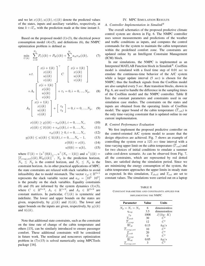
The overall schematics of the proposed predictive climatecontrol system are shown in Fig. 6. The NMPC controlleruses sensor measurements and predictions of the weatherand traffic conditions as inputs, and computes the controlcommands for the system to maintain the cabin temperaturewithin the predefined comfort zone. The constraints areupdated online by an Intelligent Constraint Management(ICM) block.
In our simulations, the NMPC is implemented as anInterpreted MATLAB Function block in Simulink®. CoolSimmodel is simulated with a fixed time step of 0.01 sec toemulate the continuous-time behavior of the A/C systemwhile a larger update interval (5 sec) is chosen for theNMPC; thus the feedback signals from the CoolSim modelare also sampled every 5 sec. Rate transition blocks, shown inFig. 6, are used to handle the difference in the sampling timesof the CoolSim model and the NMPC controller. Table IIlists the constant parameters and constraints used in oursimulation case studies. The constraints on the states andinputs are obtained from the operating limits of CoolSimmodel. The upper bound of the cabin temperature (T cab) isthe only time-varying constraint that is updated online in ourcurrent implementation.
B. Control Performance Evaluation
We first implement the proposed predictive controller onthe control-oriented A/C system model to assure that thedesign objectives are achieved. Fig. 7 shows an example ofcontrolling the system over a 125 sec time interval with atime-varying upper limit on the cabin temperature (T cab) andfor two choices of initial conditions to emulate a summercabin cool-down scenario. As can be observed from Fig. 7,all the constraints, which are represented by red dottedlines, are satisfied during the simulation period. Since weare minimizing the energy consumption of the system, thecabin temperature approaches the upper limits in steady stateas expected. In this simulation, Tshell and Tint are set toconstant values. The simulations were carried out on a laptop
TABLE IICONSTANT PARAMETERS AND CONSTRAINTS APPLIED FOR
IMPLEMENTING THE NMPC
Parameter Value Units
Np = Nc = Nu 6 dimensionlessηcop 3.5 dimensionlesscp 1008 J/(kg ·K)Tamb 30 Co
T evap 12 Co
W bl 0.15 kg/sT evap,set 10 Co
T cab 20 Co
T evap 0 Co
W bl 0.05 kg/sT evap,set 3 Co
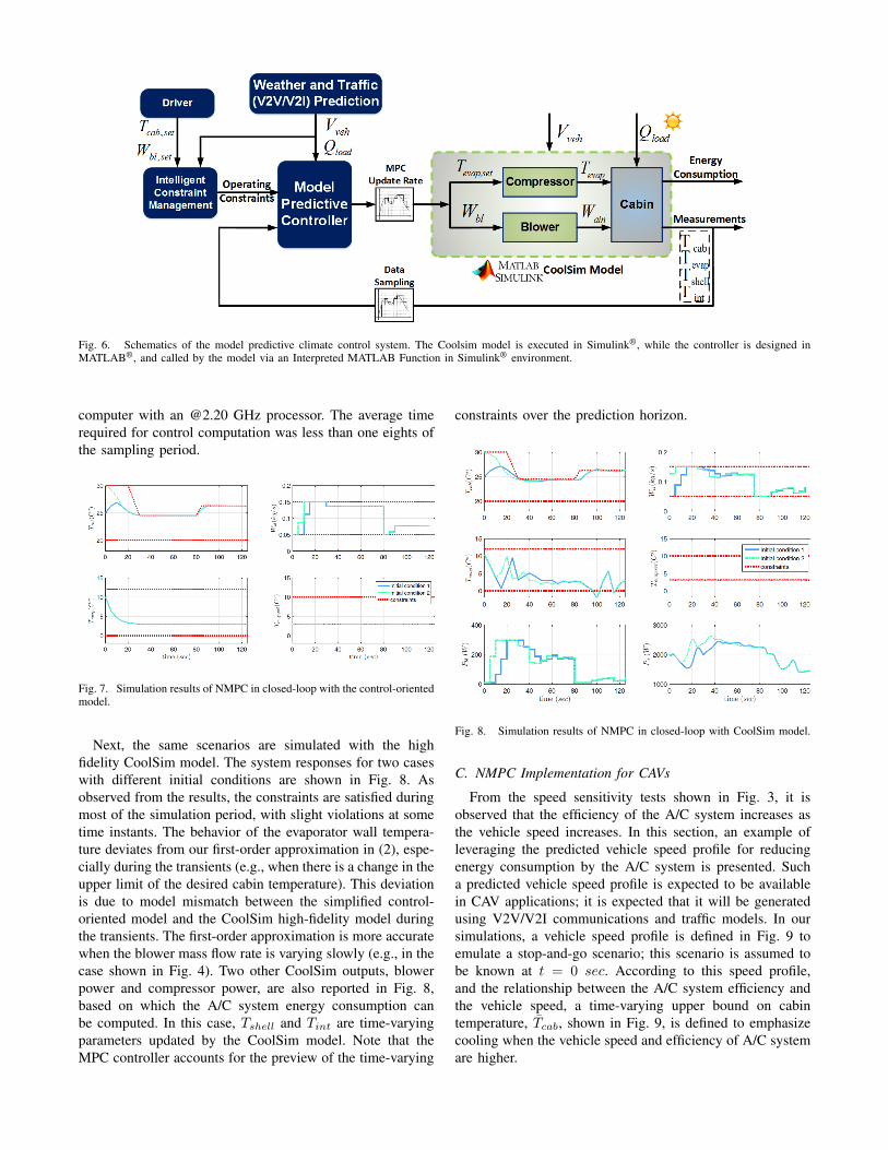
Fig. 6. Schematics of the model predictive climate control system. The Coolsim model is executed in Simulink®, while the controller is designed inMATLAB®, and called by the model via an Interpreted MATLAB Function in Simulink® environment.
computer with an @2.20 GHz processor. The average timerequired for control computation was less than one eights ofthe sampling period.
Fig. 7. Simulation results of NMPC in closed-loop with the control-orientedmodel.
Next, the same scenarios are simulated with the highfidelity CoolSim model. The system responses for two caseswith different initial conditions are shown in Fig. 8. Asobserved from the results, the constraints are satisfied duringmost of the simulation period, with slight violations at sometime instants. The behavior of the evaporator wall tempera-ture deviates from our first-order approximation in (2), espe-cially during the transients (e.g., when there is a change in theupper limit of the desired cabin temperature). This deviationis due to model mismatch between the simplified control-oriented model and the CoolSim high-fidelity model duringthe transients. The first-order approximation is more accuratewhen the blower mass flow rate is varying slowly (e.g., in thecase shown in Fig. 4). Two other CoolSim outputs, blowerpower and compressor power, are also reported in Fig. 8,based on which the A/C system energy consumption canbe computed. In this case, Tshell and Tint are time-varyingparameters updated by the CoolSim model. Note that theMPC controller accounts for the preview of the time-varying
constraints over the prediction horizon.
Fig. 8. Simulation results of NMPC in closed-loop with CoolSim model.
C. NMPC Implementation for CAVs
From the speed sensitivity tests shown in Fig. 3, it isobserved that the efficiency of the A/C system increases asthe vehicle speed increases. In this section, an example ofleveraging the predicted vehicle speed profile for reducingenergy consumption by the A/C system is presented. Sucha predicted vehicle speed profile is expected to be availablein CAV applications; it is expected that it will be generatedusing V2V/V2I communications and traffic models. In oursimulations, a vehicle speed profile is defined in Fig. 9 toemulate a stop-and-go scenario; this scenario is assumed tobe known at t = 0 sec. According to this speed profile,and the relationship between the A/C system efficiency andthe vehicle speed, a time-varying upper bound on cabintemperature, T̄cab, shown in Fig. 9, is defined to emphasizecooling when the vehicle speed and efficiency of A/C systemare higher.

Two cases are shown in Fig. 10 to demonstrate theenergy saving solutions. The simulation results of testingthe predictive climate controller based on the designed cabintemperature upper bound are shown in Fig. 10 as Case1. For this case, an open-loop compressor shut-off controlis implemented during the temperature recovering period(from 60 sec to 80 sec). In Case 2, which representsthe conventional A/C system control scheme, the controllertracks a constant cabin temperature set-point (i.e. a constantT̄cab is used by the NMPC controller). This set-point is theaverage of the temperatures within the comparison region(from 10 sec to 85 sec) of Case 1 shown in Fig. 10. The totalenergy consumptions during the comparison region for Case1 and Case 2 are 0.113 MJ and 0.124 MJ , respectively.As can be seen, 9% energy saving is achieved in this casestudy. Thus, allowing the temperature to vary within a certainpassenger comfort range, and optimizing the A/C systemoperation for the future vehicle speed profile provides addi-tional opportunities to improve energy efficiency, comparedto tracking a constant cabin temperature set-point.
Fig. 9. Assumed future speed profile and coordinated adjustment of upperbound on Tcab.
Fig. 10. Comparison between two control scenarios (Case 1: coordinatingthe A/C system operation with predicted vehicle speed, Case 2: trackingconstant cabin temperature set-point).
V. CONCLUSIONS
A model predictive climate control framework to enableenergy savings and (potentially) range extension in hybridand electric passenger cars was presented in this paper. Ex-ploiting opportunities emerging in connected and automatedvehicles, a preview of vehicle speed and weather conditionscan be integrated into HVAC control. In this work, a high
fidelity A/C system model (CoolSim) was adopted as thevirtual testbed for testing the predictive climate control algo-rithm. In order to conduct real-time optimization, a control-oriented prediction model of the A/C system was developedand validated against data from CoolSim model. Then, anonlinear MPC (NMPC) problem was formulated and solvedfor minimizing the energy consumption of the A/C system.The performance of the proposed NMPC controller wasvalidated in closed-loop with CoolSim model. In order todemonstrate the benefits of incorporating the future vehiclespeed information into the A/C control problem, a speed-correlated test scenario with a time-varying cabin tempera-ture constraint was compared with a conventional constantcabin temperature setpoint scenario. The results showed thatcoordinating the cabin temperature with the vehicle speedprofile can result in up to 9% improvement in the energyefficiency of the A/C system. Future work will addressenhancing the prediction model to include vehicle speedsensitivity, handling additional comfort constraints, incorpo-rating weather/thermal input forecasts, and co-optimizationof vehicle speed and A/C system operation.
REFERENCES
[1] J. Rugh, and R. Farrington, “Vehicle Ancillary Load Reduction ProjectClose-Out Report: An Overview of the Task and a Compilation of theResearch Results,” Technical Report, NREL/TP-540-42454, 2008.
[2] M. Jeffers, L. Chaney, and J. Rugh, “Climate Control Load Reduc-tion Strategies for Electric Drive Vehicles in Warm Weather,” SAETechnical Paper, 2015-01-0355, 2015.
[3] https://www.nrel.gov/docs/fy14osti/62241.pdf[4] C. Rostiti, S. Stockar, and M. Canova, “A Rule-based Control for
Fuel-efficient Automotive Air Conditioning Systems,” SAE TechnicalPaper, 2015-01-0366, 2015.
[5] Q. Zhang and M. Canova, “Modeling Air Conditioning System withStorage Evaporator for Vehicle Energy Management,” Applied Ther-mal Engineering, Vol. 87, pp. 779-787, 2015
[6] A. Kelman and F. Borrelli, “Bilinear Model Predictive Control of aHVAC System Using Sequential Quadratic Programming,” Proc. ofthe 18th IFAC World Congress, Milano, Italy, 2011.
[7] F. Oldewurtel, A. Parisio, C. N. Jones, D. Gyalistras, M. Gwerder, V.Stauch, B. Lehmann, and Manfred Morari, “ Use of Model PredictiveControl and Weather Forecasts for Energy Efficient Building ClimateControl,” Energy and Buildings, Vol. 45, pp. 15-17, 2012.
[8] Y. Ma, “Model Predictive Control for Energy Efficient Buildings,”Doctoral Dissertation, UC Berkeley, 2012.
[9] Q. Zhang, S.E. Li, and K. Deng, “Automotive Air Conditioning:Optimization, Control and Diagnosis,” Springer, 2016.
[10] T. Kiss, and L. Chaney, “A New Automotive Air Conditioning SystemSimulation Tool Developed in MATLAB/Simulink,” SAE Int. J. ofPassenger Cars-Mechanical Systems, Vol. 6, No. 2, pp.826-840, 2013.
[11] https://www.nrel.gov/transportation/vtm-models-tools.html[12] Q. Zhang, Y. Meng, C. Greiner, C. Soto, W. Schwartz, and M.
Jennings, “Air Conditioning System Performance and Vehicle FuelEconomy Trade-Offs for a Hybrid Electric Vehicle,” SAE TechnicalPaper, 2017-01-0171, 2017.
[13] M.A., Fayazbakhsh, and M. Bahrami, “Comprehensive Modeling ofVehicle Air Conditioning Loads using Heat Balance Method,” SAETechnical Paper, 2013-01-1507, 2013.
[14] M.S., Bhatti, “A Critical Look at R-744 and R-134a Mobile AirConditioning Systems,” SAE Technical Paper, 970527, 1997.
[15] D. Hintea, J. Kemp, J. Brusey, E. Gaura, and N. Beloe, “Applicabilityof Thermal Comfort Models to Car Cabin Environments,” Int. Conf.on Informatics in Control, Automation and Robotics, Vienna, Austria,2014.
[16] M.J. Risbeck, and J.B. Rawlings, “MPCTools: Nonlinear Model Pre-dictive Control Tools for CasADi,” 2016.