model sop-10 orifice plate - snplus.co.krorifice plate).pdf · a multistage restriction orifice...
TRANSCRIPT

DescriptionDescription
SpecificationsSpecifications
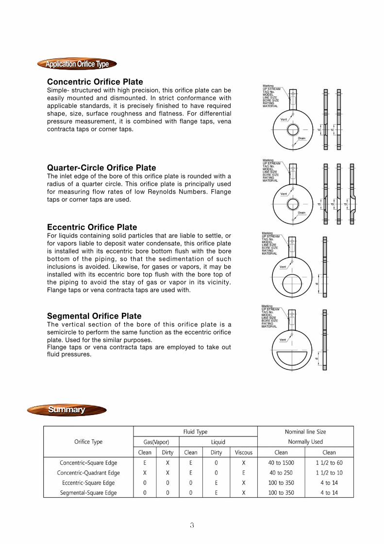
Orifice plates are widely used for measurement as theyprovide the simplest and the most economical means off low detection. Ori f ice plates are avai lable in theconcentric type that the round opening (bore) of theorifice plate is positioned concentrically with the centerof the pipe and the opening edge (bore edge) isavailable either in the concentric square edge type(sharp. Square edge type) or in the quadrant edge type(round edgy type). Orifice plates are also available inthe eccentric type that the opening of the orifice isshifted from the center of the pipe. They also areavailable in the segmental type that the opening is ac i rcu lar segmenta l segment and the or i f ice iscomparable to a partially opened gate valve
ORIFICE BORE TYPE Concentric Square Edged OrificeQuadrant Edged OrificeEccentric OrificeSegmental Orifice
FLOW CALCULATION STANDARDS ISO 5167AGA report #3ASME MFE-3M (R.W Miller)L.K.SpinkJIS Z 8762
FLANGE RATINGS JIS 10, 20, 30 etc.ANSI Class 150, 300, 600, 900 etc.
PRESSURE TAPS Flange tapsCorner tapsVena contract taps1D and 1/2D (Radius) tapsPipe taps
PLATE THICKNESS3, 6, 9, 12mm
TAB HANDLEWelded to orifice plate
PLATE MATERIAL Standard : 304SS, 316SSNon-standard : Monel, Hastelley-B/C, Titaniumetc.
DRAIN AND VENT HOLE Per ASME recommendationsNot drilled for orifice bores smaller than 25.4mm
MARKINGS Upstream s ide of tab handle stampedUPSTREAM and with bore type and size, line
size, tag number, and flange rating.
SPECIAL MARKINGS Special marking may be furnished to meetspecial requirement
Model
SOP-10 Orifice Plate
SummarySummary
Application Orifice Type
Concentric Orifice PlateSimple- structured with high precision, this orifice plate can beeasily mounted and dismounted. In strict conformance withapplicable standards, it is precisely finished to have requiredshape, size, surface roughness and flatness. For differentialpressure measurement, it is combined with flange taps, venacontracta taps or corner taps.
Quarter-Circle Orifice PlateThe inlet edge of the bore of this orifice plate is rounded with aradius of a quarter circle. This orifice plate is principally usedfor measuring flow rates of low Reynolds Numbers. Flangetaps or corner taps are used.
Eccentric Orifice PlateFor liquids containing solid particles that are liable to settle, orfor vapors liable to deposit water condensate, this orifice plateis installed with its eccentric bore bottom flush with the borebottom of the piping, so that the sedimentation of suchinclusions is avoided. Likewise, for gases or vapors, it may beinstalled with its eccentric bore top flush with the bore top ofthe piping to avoid the stay of gas or vapor in its vicinity.Flange taps or vena contracta taps are used with.
Segmental Orifice PlateThe vertical section of the bore of this orif ice plate is asemicircle to perform the same function as the eccentric orificeplate. Used for the similar purposes.Flange taps or vena contracta taps are employed to take outfluid pressures.
Application Orifice TypeApplication Orifice Type
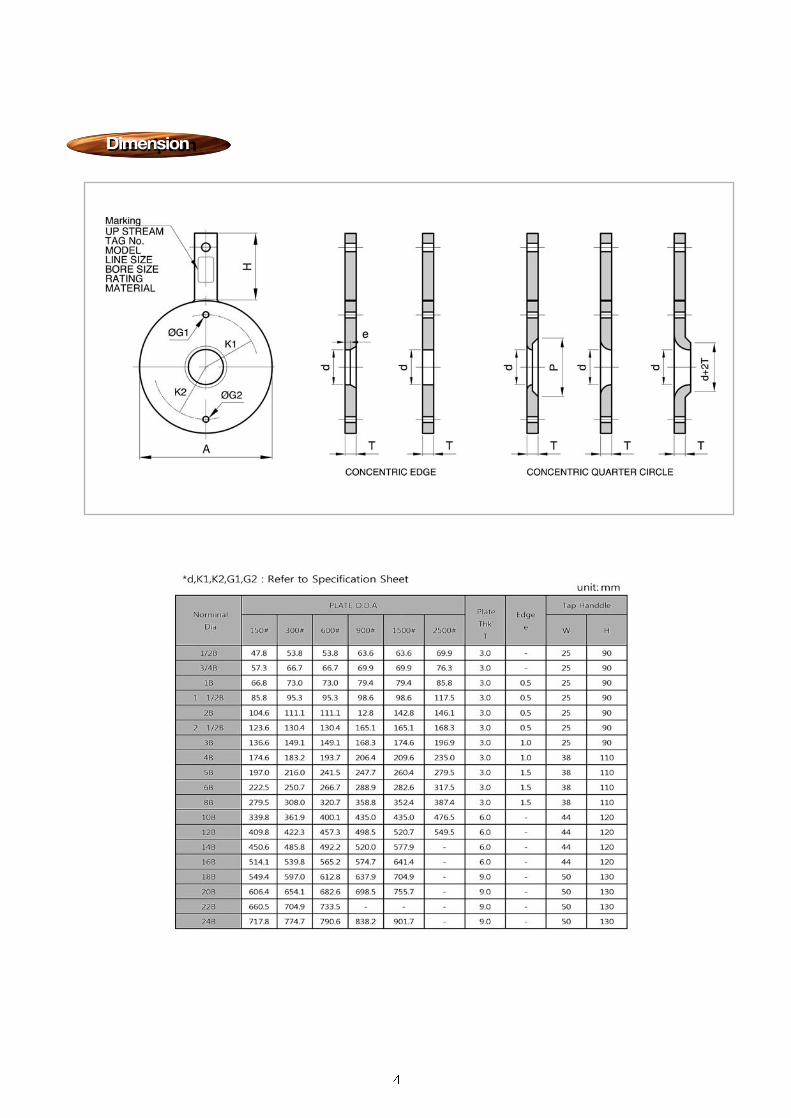
DescriptionDimension

DescriptionDescription
SpecificationsSpecifications
Ori f ice Ring Assembl ies are used for f lowmeasurement of smaller or medium sized pipe atlower pressures. Each assembly consists of oneor i f ice p late and two or i f ice r ings. D i f ferent ia lpressures are taken out in a corner tap system.Orifice Blocks, which are of a unit-construction typeand provide higher pressure ratings than the OrificeRing Assemblies, also are available.
ORIFICE BORE TYPEConcentric Square Edged OrificeQuadrant Edged OrificeMin imum quadrant edged or i f ice d iameter4.5mmMinimum quadrant edged radius 0.5mm
FLOW CALCULATION STANDARDSISO 5167JIS Z8762AGA3, 8General ApplicationL.K Spink
FLANGE RATINGSJIS 5, 10, 20 etc.ANSI (or JPI) 150, 300 etc.(Note: ANSI and JPI r ing d imensions areidentical)
PRESSURE TAPSCorner taps
PLATE THICKNESSES3, 6, 9, 12mm
TAP HANDLEWelded to orifice plate
PRESSURE TAP NIPPLES15mm (1/2 inch) Sch 40, 80Length : 150mmTap Connections : PT 1/2 or NPT male,Socket weld, Butt weld or Flange. (Flange ratingto be the same as the of the process pipeline)
DRAIN AND VENT HOLEPer ASME recommendationsNot drilled for orifice bores smaller than 25.4mm
MARKINGSSpecial marking may be furnished to meetspecial requirements
SPECIAL MARKINGSSpecial marking may be furnished to meetspecial requirements
MATERIALSRing and Pressure Tap Nipple : 304SS, 316SSPlate : 304SS, 316SS, MONEL, otherTab Handle : 304SS, 316LSS
GASKETMaterial : Asbestos, Non-Asbestos, TeflonThickness : 1.5mm, 2.0mm, 3.0mm
Model
SOP-20 Orifice Plate with Ring

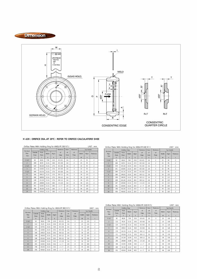
DescriptionDimension
d20 : ORIFICE DIA.AT 20 : REFER TO ORIFICE CALCULATED SHEETD : INSIDE DIA OF RING E : INSIDE DIA OF GASKET

DescriptionDescription
SpecificationsSpecifications
The Holder Ring Assembly is a combination of a holderring and an orifice plate designed for ring-type-joint(RTJ)flanges of ANSI or JPI Specifications. The holder ringhas a function of holding the orifice plate and also afunction as a gasket to prevent leakage of the processfluid. This metallic sealing system is applicable to a fluidof high temperature and high pressure. The pressuretapping system normally is of the flange tap type.
ORIFICE BORE TYPEConcentric Square Edged OrificeQuadrant Edged Orifice
FLOW CALCULATION STANDARDSISO 5167AGA 3,8General ApplicationL.K.SpinkASME-MFC-3MJIS Z 8762
FLANGE RATINGSANSI Class 300, 600, 900 etc.Ring type joint(RTJ)
PRESSURE TAPSFlange taps
PLATE THICKNESSES3, 6, 9, 12mm
TAB HANDLEWelding to ringHOLDING RINGRiveted to plateTypes : Octagonal or oval
DRAIN AND VENT HOLEPer ASME recommendationsNot drilled for orifice bores smaller than 25.4mm
MARKINGSUpstream side of tab handle stamped withUPSTREAM and with bore type and size,
Tag number, quadrant edge radius and flangerating.
SPECIAL MARKINGSSpecial marking may be furnished to meetSpecific requirement
MATERIALSPlate : 304SS, 316LSSHolding Ring : Soft Iron, 304SS or 316SSRivets : 304SS or 316SSTab Handle : 304SS or 316SS
NOMINAL PIPE SIZES AVAILABLE
Model
SOP-30 Orifice Plate with Holding Ring
DescriptionDimension


Ordering InformationsOrdering Informations
ORIFICE PLATE & RING ASSEMBLY
SOP - 10 A 1 A 1 A 1
RING MATERIALA = 304 SS B = 316 SS
OP = etc.
BORE TYPE1 = Concentric Edge2 = Quadrant Edge3 = Eccentric4 = Segmental
A = 15A(1/2 )B = 20A(3/4 )C = 25A(1 )D = 32A(1-1/2 )E = 50A(2 )F = 65A(2-1/2 )G = 80A(3 ) H = 100A(4 ) I = 125A(5 )
J = 150A(6 ) K = 200A(8 ) OP = etc.
LINE SIZE
1 = 304 SS 2 = 316 SS 3 = Titanum 4 = Monel OP = etc.
PLATE MATERIAL
10 = Orifice Plate 20 = Orifice Plate with Ring 30 = Orifice Plate with Holding Ring(Oval Type) 31 = Orifice Plate with Holding Ring(Octagonal Type)
TYPE(BASE MODEL)
1 = None2 = Drain3 = Ventoof (Ex d llC T6, IP65)
DRAIN / VENT
A = JIS 10KB = JIS 20K C = JIS 30KD = ANSI #150 E = ANSI #300 F = ANSI #600 G = ANSI #900 OP = etc.
FLANGE RATING
Printed by KOART. 2010. 01. 10-CG-F001. Rev: 0
When placing an order, selected ordering number should be indicated on the purchase order sheet.

Gas and Liquid FlowsHigh Pressure Drops
Cavitation and Flashing in Liquid FlowsChoked flow in gases.Excessive Noise /Vibration
Restriction orifice plates have traditionally been used to reduce pressures in GAS AND LIQUIDFLOWS by forcing the flow through a restricted bore. The precise pressure drop is produced byaccurately calculating the orifice bore, having taken into account all the relevant process and flowconditions.Where very HIGH PRESSURE DROPS in liquid flows are required MULTISTAGE RESTRICTIONORIFICES ASSEMBLIES may be required to achieve the desired pressure drop while preventingproblem such as CAVITATION, FLASHING and high NOISE and VIBRATION levels.
CAVITATION is a potentially damaging, erosive condition which occurs when the internal pressure ofthe liquid passing through the orifice falls below its vapour pressure and vapour bubbles form.Further downstream from the orifice the pressure recovers sufficiently to collapse the bubbles withextreme violence. Cavitation calculations are performed during the design stage of a MultistageRestriction Orifice Plate calculate cavitaion factors at each stage in the orifice assembly.
FLASHING is a similar phenomenon to cavitation except that the process pressure never recoverssufficiently to collapse the gas bubbles resulting in two phase flow-liquid and gas-downstream ofthe orifice. Erosion of pipe work and valves and other instrumentation can occur due to the impactof liquid droplets carried at high speed in the vapour flow.
CHOKED FLOW IN GASES is also known as critical flow-occurs when an excessive amount ofpressure drop is attempted across a single orifice plate. When the downstream pressure is less that52.8% of the upstream pressure, the flow through the orifice will become sonic, at which point nofurther increase in flow can be achieved by either increasing the upstream pressure or lowering thedownstream pressure. A Multistage Restriction Orifice enables to reduce the pressure as it goesthrough each plate to prevent chocked flow occuring.
DescriptionDescription
ApplicationsApplications
PreventsPrevents
The restr ict ion orif ices are used for reducing f luidpressure and are designed somewhat different from theorifice plates that are used for measuring flow rates.There are some types of restriction orifices, including asingle plate with a single hole, a single perforated plate(having diffused holes), and a set of several weldedorifices (a multistage orifice) for high pressure, hightemperature fluids.
Model
SOP-40 Restriction Orifice Plate

OverviewOverview
Multi-Stage Restriction AssemblyA multi-plate restriction assembly reducese the flowing pressure in stages as a means of reducingnoise pollution or improving the durability of the restriction element. Flow is kept subsonic and non-cavitating at each stage by adding stages. Each assembly is custom-engineered by Seojin for specificoperating parameters. Most assemblies are welded with non-removable plates. These assemblies arecommonly used in blowdown applications in which gases are vented to atmospheric pressure withminimal emitted sound.

PrinciplePrinciple
SpecificationsSpecifications
Application Fluid Liquid, Gas, SteamMaterial 304SS, 316SS, Monel, etcWorking Pressure UnlimittedWorking Temperature Max. 350 Accuracy Within 5% Evidence ISO 5167
If you want to decrease pressure p in a flux, you should determine the bore size of the orificeaccording to a formula like one above.
The conical type orifice creates an increase in velocity by reducing the flow s diameter. According toBernoulli s principle, this increase in velocity is accompanied by a corresponding decrease inpressure. This pressure differential ( ) and (Qv) has a proportional relation of Qv=K . In a regular flow volume, this pressure differential can be measured regularly. It is the same principle with the differencepressure flow meter and volume (Qv).
Qv = A2p
pp
Cd : Coefficient of Approaching VelocityA2 : Reduced AreaE : Coefficient of Approaching Speed
: Coefficient of Expansion: Density of Fluid: Pressure Lossp
Model
SOP-43 Conical Type Orifice
The Conical Type (Restriction Orifice) is a devicethat performs as a reducing valve which decreasethe pressure of fluid in the piping system, is usedin almost all the fluid like liquid, gas, steam etc.When high-pressure fluids are reduced to low-pressure, it creates cavitation and this may resultin damaging facilities by noise and vibration of thepipe.The conical type orifice allows for the reduction ofpressure by controlling the process condition toavoid cavitation.
DescriptionDescription

Ordering InformationsOrdering Informations
Printed by KOART. 2010. 01. 10-CG-F002. Rev: 0
When placing an order, selected ordering number should be indicated on the purchase order sheet.
RESTRICTION ORIFICE PLATE
SOP - 40 A 1 A 1 A
PIPE MATERIALA = A106 Gr.BB = 304 SS C = 316 SS OP = etc.
BORE TYPE1 = Concentric Edge
A = 15A(1/2 )B = 20A(3/4 )C = 25A(1 )D = 32A(1-1/2 )E = 50A(2 )F = 65A(2-1/2 )G = 80A(3 ) H = 100A(4 ) I = 125A(5 )
J = 150A(6 ) K = 200A(8 ) OP = etc.
LINE SIZE
1 = 304 SS 2 = 316 SS 3 = Titanum 4 = Monel OP = etc.
PLATE MATERIAL
40 = Restriction Orifice(Single Hole) 41 = Restriction Orifice(Multi Hole)42 = Restriction Orifice(Multi Stage)43 = Restriction Orifice(Conical Type)
TYPE(BASE MODEL)
A = JIS 10KB = JIS 20K C = JIS 30KD = ANSI #150 E = ANSI #300 F = ANSI #600 G = ANSI #900 OP = etc.
FLANGE RATING

DescriptionDescription
SpecificationsSpecifications
Ori f ice F lange Assembl ies are used inconjunct ion wi th Or i f ice P lates for f lowmeasurement of smaller or medium size pipes atlower or medium pressure ranges. The flangeconnection is of an RF type and the differentialpressure tapping system is with flange taps.
ORIFICE BORE TYPEWelding neckSlip-on Socket-weldRing-joint welding neck
NOMINAL DIAMETERS25mm(1 inch) to 500mm(20 inches)
FLANGE MATERIALA105, A182-F304, A182-F316, A182-F11,A182-F22, A350-LF2
FLANGE RATINGSJIS 10, 20, 30 etc.ANSI(or JPI) 150, 300, 600 etc.
MATERIALS OF BOLTS AND NUTS Stud bolts : A193-B7, A193-B8, A193-8MNuts : A194-2H, A194-8,A194-8MJack bolts and nuts : S25C, A307
GASKETThickness : 1.5mm, 4.5mm Material : Asbestos sheet gasket,
Spiral wound gaskets
PIPING CONNECTION METHODANSI 150# : Insertion welding type(Slip-on-type)ANSI 300#,600# : Butt welding type(Welding neck)ANSI 600# : Butt welding neck(Ring-joint WN)
DIFFERENTIAL PRESSURE PIPING CONNECTIONSelect refering to the model number construction table
Model
SOP-50 Orifice Flange Assemblies
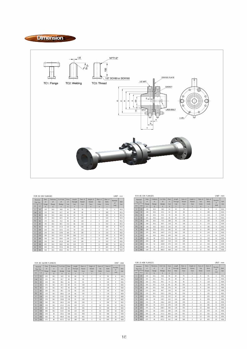
DescriptionDimension

DescriptionDimension

Pressure connection holes in the pipe should be 1/2 inch for 3-inch and larger lines, 3/4 inch for 3-inch lines, and 1/4 inch for 2-inch lines. When flange taps are used, insert a drill of the proper sizethrough the connection holes in the flanges and drill through the pipe. When connections in the pipeare used, weld half-couplings to the pipe at the proper locations, insert a drill through them, and drillthrough the pipe. Round off the edges of the holes slightly to be sure that no burrs remain in thepipe.
Basic PrincipleBasic Principle
Flange TapBoth upstream and downstream arelocated at a distance of 25mm from theorifice plate. This is also true of smallerpipes.
Corner TapTapping for di f ferent ia l pressure ismade at immediately upstream anddownstream positions of the orifice.This system is used primarily for smallpipes. (Smaller 2 )
Vena TapThe tap for the upstream side is locatedat a distance a approximately equal tothe pipe diameter. The downstream islocated at the lowest pressure position.
Radius TapID and 1/2D taps. Th is type ofconnection is a modification that haslarge ly been replaced. The VenaContracta taps, yields equally accurateresults and have the advantage of thedownstream connect ion be ing 1Dabove the upstream face of the orificeplate. But location of the upstreamconnect ion between 1/2D and 2Dintroduces only a small range of error.The downstream connection is located1/2D downstream from the upstreamface of the orifice plate.
Pipe TapThe differential pressure is small.This tapping system is not very popular.
ORIFICE FLANGE ASSEMBLIES

Ordering InformationsOrdering Informations
Printed by KOART. 2010. 01. 10-CG-F003. Rev: 0
When placing an order, selected ordering number should be indicated on the purchase order sheet.
ORIFICE PLATE & FLANGE ASSEMBLY
SOP - 50 A 1 A 1 A 1 A
PLATE MATERIALA = 304 SS B = 316 SS C = Titanum D = Monel
OP = etc.
GASKETS MATERIALA = Non Asbestos 1.5tB = Teflon 1.5tC = Spiral Wound
OP = etc.
TAP NIPPLE1 = None2 = NPT 1/ / 75L + 150L
OP= etc.
A = 15A(1/2 )B = 20A(3/4 )C = 25A(1 )D = 32A(1-1/2 )E = 50A(2 ) F = 65A(2-1/2 ) G = 80A(3 ) H = 100A(4 )I = 125A(5 )
J = 150A(6 ) K = 200A(8 )
OP = etc.
LINE SIZE
1 = Carbon Steel2 = 304 SS3 = 316 SS4 = etc
OP= .
FLANGE MATERIAL
50 = Orifice Flange Assembly(Welding Neck Type)51 = Orifice Flange Assembly(Socket-Welding Type)52 = Orifice Flange Assembly(Slip-On Type)53 = Orifice Flange Assembly(RTJ Type)
TYPE(BASE MODEL)
1 = B7 / 2H2 = B8 / 8
OP= etc.
BOLT / NUT MATERIAL
A = JIS 10KB = JIS 20K C = JIS 30KD = ANSI #150 E = ANSI #300 F = ANSI #600 G = ANSI #900
OP = etc.
FLANGE RATING