model-to-model transformations of architecture ......transformations were performed in the ibm...
TRANSCRIPT
Journal of Theoretical and Applied Computer Science Vol. 8, No. 2, 2014, pp. 48-62 ISSN 2299-2634 (printed), 2300-5653 (online) http://www.jtacs.org
Model-to-model transformations of architecture
descriptions of an integration platform
Tomasz Górski
Faculty of Cybernetics, Military University of Technology, Warsaw, Poland
Abstract: Model transformations play a key role in any software development project based on Mod-
el-Driven Engineering (MDE) principles. However, little attention has been paid to the ap-
plication of MDE principles to automate the design of integration solutions. The aim of the
paper is to present transformations of a model-to-model type, used to automate the process
of integration platform’s architecture description. The transformations have been designed
to enable the generation of model elements, according to the ‘1+5’ architectural views
model adjusted to the integration solutions description. Design and implementation of
transformations were performed in the IBM Rational Software Architect (RSA) environ-
ment. Authorial UML profiles: UML Profile for Integration Platform and UML Profile for
Integration Flows have been used. The paper covers transformations between models in the
following architectural views: Integrated Processes; Use Cases; Logical and Integrated
Services. The transformations occur at the levels of business processes, requirements speci-
fication and system design. Using the transformations, it is possible to generate models,
diagrams, model elements and relationships between them. The complete environment has
been obtained to automate architectural description of an integration solution. Transfor-
mations ensure completeness of the architectural description and consistency of elements
between models.
Keywords: Model Driven Architecture (MDA); Software Architecture; Enterprise Application Integra-
tion (EAI); Application Integration
1. Introduction
A matter of key importance to companies is the ability to provide services or products promptly, which meet the needs of potential clients. The time taken for order processing or responding to incoming requests is another vital issue. It is necessary to provide appropriate support to business processes by means of information technology to meet these challenges. Most commonly, an organization operates a variety of IT systems. This implies the need to build integration solutions comprised of IT systems and a communication layer that enables cooperation between these systems. A solution of this type is called an integration platform, or an integration solution. When designing integration solutions, it is essential to be able to model their complete architectural description. For this purpose, one needs to have an archi-tectural views model which allows for modelling integration platforms and a set of model constructs enabling presentation of the integration platform’s entire architecture [12, 13]. The integration of many various IT systems makes the integration project highly complex. Using transformations, the Integration Architect automates the process of constructing ar-
Model-to-model transformations of architecture descriptions of an integration platform 49
chitecture models, thereby reducing the design process duration and the volume of work it involves, while bringing down the number of errors [14, 20, 30]. The issue is analysed more broadly in Section 12 of the paper. The use of transformations is an element of the Model-Driven Engineering approach (MDE) [19, 21, 27]. The aim of the paper is to present trans-formations of a model-to-model type, used to automate the process of designing the integra-tion platform architecture. The article uses an architectural views model ‘1+5’ presented by Górski [12]. The models being transformed represent different levels of abstraction. From the perspective of notation, models expressed in the same notation — Unified Modeling Language — are subject to three of the transformations presented here, while models ex-pressed in different notations — Business Process Model and Notation [8] and UML — are subject to one of the transformations. The remainder of the paper is structured as follows. Section 2 presents views, models and diagrams of the architectural views model ‘1+5’. Sec-tion 3 introduces the subject of transformations. Section 4 contains an overview of publica-tions dedicated to similar problems. Section 5 introduces the transformation implementation environment IBM Rational Software Architect. Section 6 describes transformations de-signed for automation of the integration platform architecture design. Sections 7, 8, 9 and 10 present details of the four transformations. Section 11 explains automation of constructing structures of the models generated by the transformations. Section 12 concludes the paper, summing up the subject and outlining the advantages of using transformations in the context of effort, project duration and the number of errors involved. In addition, the conclusion outlines directions for further work.
2. Architectural views model ‘1+5’
Consistency of the architectural description of IT solutions is a significant matter and the subject of studies today [1]. A variety of models exists, with differing sets of architectural views, such as, for example: ‘4+1’, RM-ODP, Siemens, SEI views [26]. Yet, they do not allow for a complete description of the integration solutions architecture. The ‘1+5’ model of architectural views proposed here has been accommodated to suit the process of an inte-gration platform design [12]. The following architectural views have been distinguished within the model:
− Integrated Processes − Use Cases − Logical − Integrated Services − Contracts − Deployment. The view of Integrated Processes is the basic architectural view here. In this view, busi-
ness processes to be automated on the integration platform are modelled. The next four views (Use Cases, Logical, Integrated Services and Contracts) present the integration plat-form design. The Use Cases view contains functional requirements for the system being integrated within the platform. The view of Integrated Services presents services exposed by IT systems, and the way how they are connected to the service bus. The Contracts view shows components representing IT systems and the contracts defined between them. This view also encompasses mediation flows for each contract. The last view, Deployment,
shows the way the integration platform elements are deployed in a certain runtime environ-ment. Figure 1 illustrates the architectural views model ‘1+5’.
A detailed description of the architectural views model referred to above and examples of its application can be found in the literature [12, 13]. In the approach analysed here,

50 Tomasz Górski
models and diagrams of BPMN [5] and UML [29] languages, with an extension of Service oriented architecture Modeling Language stereotypes [28] have been used for modelling the integration platform architecture (Table 1).
Figure 1. The architectural views model ‘1+5’
Table 1. Elements for modelling the integration platform architecture
Model View Diagram
Processes Integrated Processes (BPMN) Business Process Use Cases Use Cases (UML) Use Case
(UML) Activity Design Logical (UML) Sequence
(UML) Communication (UML) Class
Services Integrated Services (UML) Component Contracts (UML) Component
(UML) Activity (UML) Composite Structure
Deployment Deployment (UML) Deployment
3. Transformations
The literature on the subject [7, 24] provides the following definition of the model-to-model transformation:
Transformation is the automatic generation of a target model from a source
model, according to a transformation definition. A transformation definition is a set
of transformation rules that together describe how a model in the source language
can be transformed into a model in the target language. A transformation rule is a
description of how one or more constructs in the source language can be trans-
formed into one or more constructs in the target language [19: p. 24]. To be transformable, models have to be expressed in a modelling language. Each model
needs to be consistent with the metamodel, which defines the syntax and semantics of a cer-

Model-to-model transformations of architecture descriptions of an integration platform 51
tain type of model. In the same way, the metamodel has to be consistent with a meta-metamodel. As a rule, the meta-metamodel defines itself, which means that it can be speci-fied by means of its own semantics. Metamodels are usually defined by means of a UML class diagram. Yet, there are other languages there, suitable for this purpose [7]: e.g. Meta-Object Facility; Ecore meta-metamodel, defined for the Eclipse Modelling Framework envi-ronment; and Kernel MetaMetaModel. Furthermore, various approaches are adopted to define and start transformations. Some of these are based on direct manipulation, where transformations are generated in a programming language which operates on models in the computer’s operating memory (e.g. Java Metadata Interface); some are declarative, where transformation rules are defined as mathematical rules(e.g. Query/View/Transformation [25]); and some use graph transformations, where models are presented as graphs (e.g. At-tribute Graph Grammar). Based on a modelling language in which the source model and the target model are expressed, one may distinguish endogenous and exogenous transformations [24]. Endogenous transformations occur between models expressed in the same modelling language. Exogenous transformations, on the other hand, are transformations between mod-els expressed in different modelling languages. Furthermore, transformations can be catego-rized as horizontal and vertical [24]. A horizontal transformation occurs when both the source model and the target model represent the same abstraction level, whereas when the source and target models are at different abstraction levels, the transformation is defined as a vertical one. Moreover, model transformations can be unidirectional or bidirectional [24]. In the case of unidirectional transformations, the target model can be generated from the source model, while in bidirectional transformations, the source and the target model remain consistent, regardless of which of alterations are made. In a bidirectional transformation, a traceability relationship has to be used, to establish links between elements of the models being transformed [27].
4. Related studies
An overview of the literature below follows the process described in the Systematic Re-view method [18]. The literature on the subject is rich in model transformations problems. Details of the model transformation taxonomy are presented in [24]. Publications describe various languages that can be used for generating transformations: Que-ry/View/Transformation (QVT) [25] and ATL (Atlas Transformation Language) [3, 16]. In publications of recent years, special focus has been on the topical and vital issues of model-to-model transformations verification and validation. Verification and validation of model transformations through invariants are presented in [6]. Moreover, the study proposes how the QVT language can be used for constructing a declarative language for the specification of visual contracts, which enables verification of transformations defined in any language of transformation [15]. An up-to-date, comprehensive overview of the model transformation verification problems is given in [7]. The article focuses on presenting model transfor-mations required for automation of designing a certain type of system; namely, integration platforms. These transformations have been designed according to requirements of the ar-chitectural views model ‘1+5’. The transformation of a BPMN process diagram into a UML use case diagram is a new, authorial proposal for identifying use cases of IT systems which are the subject of integration. In addition, the study presents a new, authorial profile: ‘UML Profile for Integration Platform’ with the <<IntegratedSystem>> stereotype [13]. Transfor-mation of BPMN models is a subject of current interest in the literature. For example, [23] discusses the issue of bidirectional transformation between BPMN and Business Process Execution Language models. Furthermore, some publications present model transformations

52 Tomasz Górski
transforming BPMN models into UML models. Here, BPMN models are transformed into UML activity diagrams [9, 22]. Frece and Juric [11] present an approach to the dynamic identification of services from the BPMN model, but models are not created explicitly in UML. The study proposes a meta-model for the formal specification of functional require-ments for the dynamic selection of services in business process models. The remaining transformations discussed in the article deal with the transformation of UML models. Two of them are new proposals developed by the author for the transformation of a Use Cases model into a Services model, proposed in the ‘1+5’ architectural views model. In the last transformation, a Use Cases model is transformed into a Design model, and constitutes an extension of a transformation, which was available in IBM Rational Software Architect 6.0, and which generated use cases realizations, as well as analytical classes with <<boundary>> and<<control>> stereotypes.
5. The environment for transformations design
In the IBM Rational Software Architect (RSA) environment, it is possible to use the transformations available there, as well as to construct one’s own. RSA enables the con-struction of the following types of transformation: code-to-model (models are generated from a source code); model-to-code (a source code is generated, e.g.: C++, Java, on the ba-sis of a model); and model-to-model (a model is generated, e.g. UML, BPMN, based on some other model). The focus of the present paper is on model-to-model transformations. The RSA tool is an extension of the Eclipse environment and uses the Ecore meta-metamodel [10]. Each transformation consists of three elements: a source model; a target model; and the mapping between them. The element which can be mapped onto Ecore mod-
el class element or onto an UML profile is always the source of the model-to-model trans-formation. Package and Model class elements from the org.eclipse.uml2.uml package, and Definitions from the com.ibm.xtools.bpmn2 package can be indicated as sources of trans-formation. BPMN and UML model elements are defined in Ecore. A definition of the Ecore model for BPMN is contained in file plugin/com.ibm.xtools.bpmn2/model/bpmn2.ecore, while a definition of the Ecore model for UML is included in file plugin/org.eclipse.uml2.uml/model/UML.ecore. In addition, an object inherited from the Ecore model or a UML profile should also be given as the target model of transformation. The mapping between the source model and the target model is the last defining element. The mapping is expressed on several levels. The source model mapping in the target model of the entire transformation occurs on the highest level. The highest level shows the main elements of mapping; e.g. Definitions in the source model and Package in the target model. Thereafter, mappings between attributes contained in the elements of mapping can be de-fined. For example, the Name attribute from the Definitions element can be transformed into the Name attribute of the Package element. When defining the mapping between the attrib-utes of elements, one should specify the type of mapping. The Custom and Submap map-pings allow for a high flexibility of the transformation’s design. With the Custom type of mapping, a method written in Java can be linked, to effect the transformation between the attributes of elements. Using the Submap type enables the decomposition of the mapping and the formation of nested mapping inside it. The operation of transformation is imple-mented in Java class, and run by invoking appropriate methods of the class. Java class methods executing the transformation have access to both the source and the target model saved as XML files. Examples of mapping and methods of Java classes implementing trans-formations will be presented further on, when concrete transformations will be described.
Model-to-model transformations of architecture descriptions of an integration platform 53
6. Transformations automating the integration platform architecture
design
Chief Analyst and Chief Architect are the key roles in the analytical work, and in design as well. During the process of modelling the integration platform architecture, models listed in Table are constructed, which present different architectural views. The first model created is the model of Processes. It is the Chief Analyst’s responsibility to develop the model. With the model of Processes ready, one should think about automating the process of developing the Use Cases model, which sources model constructs from the first one. Owing to trans-formation, some of the Use Cases model structures and elements can be obtained in an au-tomated manner. Thereafter, the Use Cases model has to be completed by analysts. Transformations enabling the development of model structures and elements in the Design model and the Services model can be applied only after the Use Cases model is complete. The two models — Design and Services — include elements which describe the integration platform architecture in the Logical, the Contracts and the Integrated Services views. Here, three transformations are proposed, generating design elements from the Use Cases model, which describes a specification of functional requirements. The Deployment model de-scribes the physical distribution of the software on hardware servers, as well as runtime en-vironments. It has been excluded from the area of automating the integration platform architectural description.
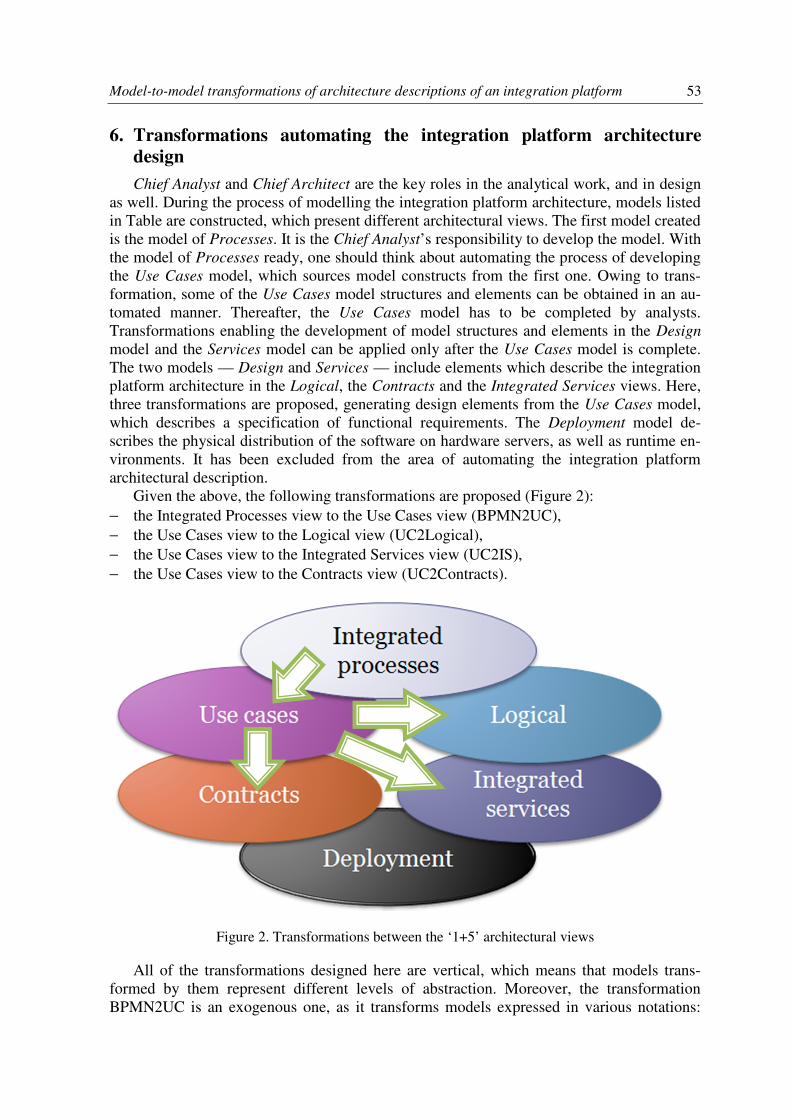
Given the above, the following transformations are proposed (Figure 2): − the Integrated Processes view to the Use Cases view (BPMN2UC), − the Use Cases view to the Logical view (UC2Logical), − the Use Cases view to the Integrated Services view (UC2IS), − the Use Cases view to the Contracts view (UC2Contracts).
Figure 2. Transformations between the ‘1+5’ architectural views
All of the transformations designed here are vertical, which means that models trans-formed by them represent different levels of abstraction. Moreover, the transformation BPMN2UC is an exogenous one, as it transforms models expressed in various notations:
54 Tomasz Górski
BPMN and UML. The remaining transformations analysed in this article are endogenous, and transform models expressed in UML. A comprehensive classification of transfor-mations can be found in [24].
7. Transformation of the Integrated Processes view into the Use Cases
view
The purpose of the transformation is to obtain Use Cases models for IT systems being integrated. The Integrated Processes view presents processes of the organization. It has been assumed that for each organization in the Processes model a separate Use Cases model is developed, which specifies functional requirements for a separate IT system. A list of employees identified for the given organization is used as a basis for establishing actors in the Use Cases model, which represents the IT system developed for this organization. A similar procedure applies to business process tasks. Namely, tasks identified within the or-ganization’s process are used as a basis for developing use cases within the Use Cases mod-el, which represents the IT system developed for this organization. The BPMN model represented in RSA as a file with the bpmx extension is taken as an input to the transfor-mation. All types of BPMN diagrams used in RSA can be transformed: choreography, col-laboration and process. Yet, as far as semantics are concerned, transformation should be used for the collaboration and process type diagrams. For transformation to be executed correctly, the following initial requirements have been pre-defined for the source model expressed in BPMN: − each Resource type element should represent the organization − each Lane type element represents an employee − each Lane type element representing an employee should be linked by PartitionElement
to the organization to which it belongs − tasks performed by an employee should be positioned on their lane.
The output model has to be expressed in UML. Within the output model a package is developed, which contains many Use Cases models representing organizations in the BPMN process diagram. Two packages are created inside each model. The first of these contains actors and their association relationships with use cases, while the second one con-tains use cases. System actors are created in UML, based on lanes in BPMN. Use cases rep-resent tasks performed by the employees. The association relationships between actors and use cases reflect employees performing these tasks. Figure 3 illustrates mapping defined for transformation BPMN2UC.
The figure depicts two mappings. The upper one is responsible for naming the package. The lower mapping performs the entire transformation and is responsible for creating the package contents in the target model. The Java BPMN2UC class and mainBPMN2UC oper-ation call, with two input parameters representing the source model (Definitions) and the target model (Package), are linked to the lower mapping (Figure 4).
An algorithm for the transformation process is as follows: − All processes included in the input model (Definitions object) are selected. There will be
one process for a process type diagram. − For each process, lanes representing employees are selected. Only the lanes connected
with a Resource type object (representing the organization) are taken into consideration. − If no model representing the Resource type element exists in the output package, a new
model is created, named the same as the Resource element. Thereafter, two packages are

Model-to-model transformations of architecture descriptions of an integration platform 55
added to the model: Actors and Use Cases. In the Actors package, an actor named with the same name as the lane is added.
− Tasks are taken from each lane. In the Use Cases package of the model matching the Resource element, a use case with the same name as the task name is added. Thereafter, an association relationship is established between the actor, based on the lane and the use case which represents the task from this lane.
Figure 3. Mapping for the BPMN2UC transformation
public class BPMN2UC {
public static void main BPMN2UC(Definitions bpmn, Package ucPerspective){
EList<RootElement>rootElements = bpmn.getRootElements();
Iterator<RootElement>rootElementsIterator = rootElements.iterator();
while(rootElementsIterator.hasNext()){
RootElementrootElement = rootElementsIterator.next();
if(rootElementinstanceof Process){
--- transformation body ---
}
}
private static Actor addActor(Lane lane, Package actorsPackage){
if(actorsPackage.getPackagedElement(lane.getName()) != null){
if(actorsPackage.getPackagedElement(lane.getName()) instanceof Actor){
return (Actor) actorsPackage.getPackagedElement(lane.getName());}
else{
return (Actor) actorsPackage.createPackagedElement(lane.getName(),
UMLPackage.eINSTANCE.getActor());}}
else{ return (Actor) actorsPackage.createPackagedElement(lane.getName(),
UMLPackage.eINSTANCE.getActor());}
}
}
Figure 4. A fragment of Java BPMN2UC class which is responsible for transformation from BPMN to UML

56 Tomasz Górski
IT systems are developed in order to support the execution of tasks within business pro-cesses. It is therefore highly probable that a considerable part of functionalities of the IT systems being integrated results from the tasks the business processes comprise. A trans-formation such as this gives the Chief Analyst a complete set of candidate use cases, which support the organization’s business processes. An automatic transition occurs from the level of organization description to the level where requirements for IT systems are specified. Further transformations bring us from the level of requirements specification to the level of the IT system design.
8. Transformation of the Use Cases view to the Logical view
Following verification and specification of use cases by the analysts, elements of the Design model can be generated. In this transformation, the source model has to be con-sistent with the target model of the BPMN2UC transformation. A use case realization is the basic construct in the Design model. It is modelled as collaboration with the <<UseCaseRe-alization>> stereotype. The use case realization groups design elements that execute the flow of events defined in the use case. The structure of design elements in the use case real-ization, as well as their interactions, is presented on sequence, communication and class diagrams. TheUC2Logical transformation creates sequence and class diagrams. Communi-cation diagrams have been left out, as they can be generated automatically in RSA, based on sequence diagrams. As a transformation output, a package named Design model is created. The first mapping between name elements names the target package. The next mapping is of the Submap type between packagedElement attributes. The packagedElement attribute is a list storing all elements contained in the package. The purpose of this mapping is to map the source package Model class elements onto the target package Model class elements. This has been effected by nested mapping. The last mapping — of the Custom type — fills the target packages with suitable elements. The Java-class UC2Logical and the addDiagrams
operation call, with two input parameters representing the source model (Package) and the target model (Package), have been linked to this mapping.
9. Transformation of the Use Cases view to the Integrated Services view
Following verification and specification of use cases by the analysts, model constructs can be generated in the Services model. Each Use Cases model is developed for a separate IT system. On the use cases diagrams, use cases and actors of the system, as well as the IT systems integrated by the service bus, are shown. The IT system playing the role of a system being integrated by the service bus is designated by the <<IntegratedSystem>> stereotype, from the UML Profile for Integration Platform [13]. If the use cases diagram includes a system with the <<IntegratedSystem>> stereotype, associated with at least one use case, components representing the system being described and the system being integrated will be generated in the Services model. Moreover, a component serving as the service bus will be created with the <<ESB>> stereotype from the UML Profile for Integration Platform [13]. An interface will be established with an operation corresponding to the use case with which the system being integrated is in a direct association relationship. In addition, a link will be created between components corresponding to systems from the Use Cases model. A link such as this is realized by the service bus. Depending on the direction of the association relationship between the system being integrated and the use case, the service provider and the client are identified. If the association is directed towards the use case, the component representing the system in which the use case is contained is the service provider. If the as-

Model-to-model transformations of architecture descriptions of an integration platform 57
sociation is directed towards the system being integrated, the respective component is the service provider. All components displaying or using services are denoted by the <<Capa-bility>> stereotype. The component representing the service provider is stereotyped <<Pro-vider>>, while the component using the service is stereotyped <<Consumer>>. All of these are SoaML stereotypes [28]. The Use Cases model is the transformation input. For each of the models, Actors and UseCases packages must be created. All Actor class objects should fall into the Actors package. Use cases should fall into the UseCases package. If in one of the models an actor represents the system being integrated, it must be stereotyped <<Inte-gratedSystem>> and its name has to be identical to the name of the model representing the system being integrated. A package named Services Model is created as the transformation output. Inside the package, an Integrated services perspective package is set up. In the Inte-
grated services perspective package, a component named ESB is created and stereotyped <<ESB>>. For each of the systems being integrated, one component is created and named after the system. For each of the use cases being used by an external system, an interface is established. For each relationship between the use case and the actor stereotyped <<Inte-gratedSystem>> (from Use Cases model) following actions are realized.
If the relationship is oriented from the actor towards the use case, then (in Services model): − an Interface Realization relationship is established from the component representing the
system realizing the use case to the interface which represents the use case. − an Usage relationship is established from the component represented by the actor to the
interface representing the use case. − the component representing the actor is stereotyped <<Capability>> and
<<Consumer>>. − the component representing the system which realizes the use case is stereotyped <<Ca-
pability>> and <<Provider>>. − the ESB component is assigned both the Usage and the Interface Realization relation-
ship to the interface representing the use case. If the relationship is oriented from the use case to the actor, then (in Services model) el-
ements similar to the above are created, the only difference being that the component repre-senting the system which realizes the use case changes roles with the component representing the actor.
If the relationship is a bi-directional one, then (in Services model) both variants present-ed above take place.
The Interface Realization type relationships are indicated by interfaces displayed by the component. The Usage type relationships are indicated by interfaces required by the com-ponent. The <<Provider>> stereotype is used to designate the service provider, while the <<Consumer>> stereotype is used to designate the service recipient.
In the UC2IS transformation four Custom type mappings have been used here. The first mapping assigns the name of Services Model to the model. The purpose of the second map-ping is to create an Integrated services perspective package and an ESB component. Be-sides, in the first mapping, profiles containing the stereotypes needed — <<ESB>>, <<Capability>>, <<Provider>>, <<Consumer>> — are searched for in the source package. In the Integrated services perspective package, a component named ESB and stereotyped <<ESB>> is created.
The third transformation supplements the Integrated services perspective package with appropriate components. Its role is to search through all of the elements in the source pack-
58 Tomasz Górski
age. When a Model class instance is found, a component with the same name as the model instance is created in the output package.
An algorithm for the transformation process is as follows: − getting all required stereotypes. − selecting all models from the input package. The transformation takes the following
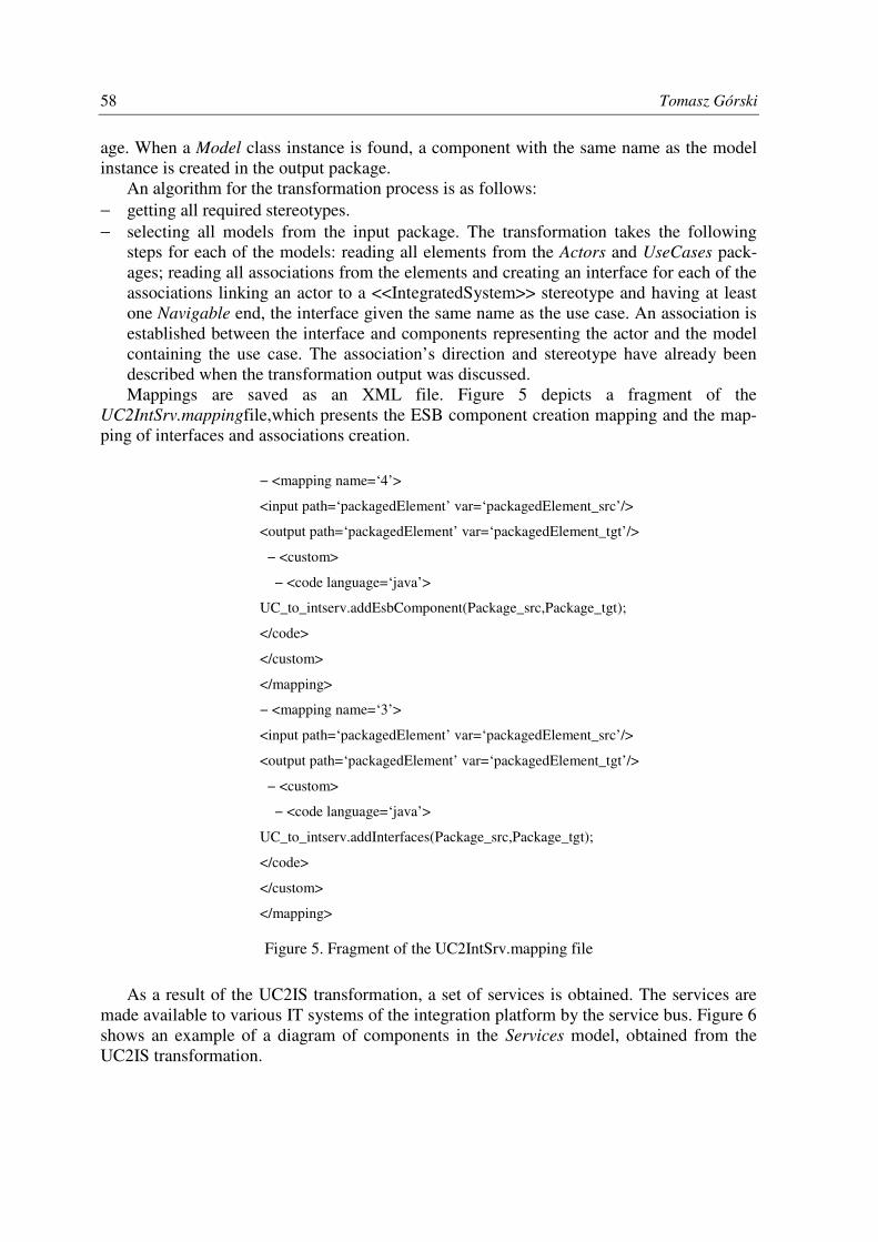
steps for each of the models: reading all elements from the Actors and UseCases pack-ages; reading all associations from the elements and creating an interface for each of the associations linking an actor to a <<IntegratedSystem>> stereotype and having at least one Navigable end, the interface given the same name as the use case. An association is established between the interface and components representing the actor and the model containing the use case. The association’s direction and stereotype have already been described when the transformation output was discussed. Mappings are saved as an XML file. Figure 5 depicts a fragment of the
UC2IntSrv.mappingfile,which presents the ESB component creation mapping and the map-ping of interfaces and associations creation.
− <mapping name=‘4’>
<input path=‘packagedElement’ var=‘packagedElement_src’/>
<output path=‘packagedElement’ var=‘packagedElement_tgt’/>
− <custom>
− <code language=‘java’>
UC_to_intserv.addEsbComponent(Package_src,Package_tgt);
</code>
</custom>
</mapping>
− <mapping name=‘3’>
<input path=‘packagedElement’ var=‘packagedElement_src’/>
<output path=‘packagedElement’ var=‘packagedElement_tgt’/>
− <custom>
− <code language=‘java’>
UC_to_intserv.addInterfaces(Package_src,Package_tgt);
</code>
</custom>
</mapping>
Figure 5. Fragment of the UC2IntSrv.mapping file
As a result of the UC2IS transformation, a set of services is obtained. The services are made available to various IT systems of the integration platform by the service bus. Figure 6 shows an example of a diagram of components in the Services model, obtained from the UC2IS transformation.

Model-to-model transformations of architecture descriptions of an integration platform 59
Figure 6. An example of an UML component diagram obtained from the UC2IS transformation
10. Transformation of the Use Cases view to the Contracts view
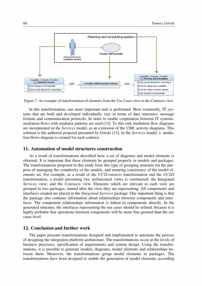
Taking the use cases verified and specified in the Use Cases model as a basis, it is pos-sible to generate contracts in the Services model. Components representing the systems are obtained as a result of transformation of the Use Cases view to the Integrated Services view. For each relationship between a use case and an actor with the <<IntegratedSystem>> stere-otype, a contract is created and named after the use case. The contract is linked by the Us-
age relationship to the components representing the system being integrated, and the system realizing the use case. Figure 7 shows an example of transformation of the Use Cases view to the Contracts view.
60 Tomasz Górski
Figure 7. An example of transformation of elements from the Use Cases view to the Contracts view
In this transformation, one more important task is performed. Most commonly, IT sys-tems that are built and developed individually vary in terms of data structures, message formats and communication protocols. In order to enable cooperation between IT systems, mediation flows with mediator patterns are used [13]. To this end, mediation flow diagrams are incorporated in the Services model, as an extension of the UML activity diagrams. This solution is the authorial proposal presented by Górski [13]. In the Services model, a media-tion flows diagram is created for each contract.
11. Automation of model structures construction
As a result of transformations described here, a set of diagrams and model elements is obtained. It is important that these elements be grouped properly in models and packages. The transformations proposed in this study form this type of grouping structure for the pur-pose of managing the complexity of the models, and ensuring consistency of the model el-ements set. For example, as a result of the UC2Contracts transformation and the UC2IS
transformation, a model presenting two architectural views is constructed: the Integrated Services view; and the Contracts view. Elements which are relevant to each view are grouped in two packages, named after the view they are representing. All components and interfaces created are placed in the Integrated Services package. One important thing is that the package also contains information about relationships between components and inter-faces. The component relationships information is linked to components directly. In the generated structure, the interfaces representing the use cases should be refined, because it is highly probable that operations between components will be more fine-grained than the use cases level.
12. Conclusion and further work
The paper presents transformations designed and implemented to automate the process of designing the integration platform architecture. The transformations occur at the levels of business processes, specification of requirements and system design. Using the transfor-mations, it is possible to generate models, diagrams, model elements and relationships be-tween them. Moreover, the transformations group model elements in packages. The transformations have been designed to enable the generation of model elements, according

Model-to-model transformations of architecture descriptions of an integration platform 61
to the ‘1+5’ architectural views model adjusted to the integration solutions description. Au-thorial UML profiles: UML Profile for Integration Platform and UML Profile for Integra-
tion Flows [13] have been used. Owing to transformations, it is possible to reduce the time needed for architectural description significantly, and to avoid a great many errors. This is particularly important when designing complex solutions integrating multiple IT systems. The available analyses of IT systems designed in the sector of medicine show that where model-driven engineering is applied, the software development process duration is recorded to be three times shorter [14, 30]. The economies resulting from the use of model-driven engineering in designing IT solutions for Internet applications are more than twofold (reduc-tion of the software development time by 59%) [20]. Moreover, transformations ensure completeness of the architectural description and consistency of elements between models. Studies have proved that with transformations, the number of software errors reported is ten times lower [14, 30]. The possibility of reducing the time of software development while improving its quality results in the fact that models are becoming the basic artefact in the process of software development. It is, therefore, crucial and topical to ensure an adequate level of model quality [2, 17]. So far, the main emphasis of the research work has been on assuring quality of transformations through verification and validation [7, 3, 6, 15]. Fur-thermore, the literature on the subject includes publications describing model-driven engi-neering applications for the automated generation of model transformations [4]. It would be interesting to see further work to develop a quality assurance method for the models being transformed, as well as for the transformation proper. Plans include the improvement of the BPMN2UC transformation flexibility towards using an XML file as a source element. Such evolution would enable the BPMN2UC transformation to transform process models devel-oped in any tool saving a BPMN model in the XML format. Adding traceability to the trans-formation design, and enabling the target model update following the source model modification would be another beneficial development [27]. Furthermore, bidirectional transformations would be constructed [23]. Moreover, plans include adding a model-to-code type of transformation, as well as generating a source code for classes, services and media-tion flows from the models.
References
[1] Abi-Antoun, M., Aldrich, J., Nahas, N., Schmerl, B., Garlan, D., 2008. Differencing and merg-ing of architectural views, Automated Software Engineering 15 35–74.
[2] Arendt, T., Taentzer, G., 2013. A tool environment for quality assurance based on the Eclipse Modeling Framework, Automated Software Engineering 20 141–184.
[3] Bézivin, J., Jouault, F., 2006. Using ATL for checking models, Electronic Notes In Theoretical Computer Science 152 69–81.
[4] Bollati, V. A., Vara, J. M., Jiménez, Á., Marcos, E., 2013. Applying MDE to the (semi-) auto-matic development of model transformations, Information and Softw. Technology 55 699–718.
[5] Business Process Model and Notation (BPMN) 2.0, OMG 2011, www.omg.org/spec/ BPMN/2.0. (accessed 8 August 2014).
[6] Cabot, J., Clarisó, R., Guerra, E., de Lara, J., 2010. Verification and validation of declarative model-to-model transformations through invariants, The Journal of Systems and Software 83 283–302.
[7] Calegari, D., Szasz, N., 2013. Verification of model transformations a survey of the State-of-the-art., Electronic Notes In Theoretical Computer Science 292 5–25.
[8] Chinosi, M., Trombetta, A., 2012. BPMN: An introduction to the standard, Computer Stand-ards & Interfaces 34 124–134.
62 Tomasz Górski
[9] Cibrán, M. A., 2009. Translating BPMN Models into UML Activities, Lecture Notes in Busi-ness Information Processing 17 236–247.
[10] Ecore Package API Javadoc - download.eclipse.org/modeling/emf/emf/javadoc/2.9.0/ org/eclipse/emf/ecore/package-summary.html (accessed 8 August 2014).
[11] Frece, A., Juric, M. B., 2012. Modelling functional requirements for configurable content- and context-aware dynamic service selection in business process models, J. of Vis. Languages and Computing 23 223–247.
[12] Górski, T., 2012. Architectural view model for an integration platform, J. of Theoretical and Appl. Computer Science, 6 (1) 25–34.
[13] Górski, T., 2013. UML profiles for architecture description of an integration platform, Biul. of Military University of Technology, 2 43-56.
[14] Groote, J. F., Osaiweran, A. A. H., Wesselius, J. H., 2011. Analyzing the effects of formal methods on the development of industrial control software, IEEE ICSM 2011, 467–472.
[15] Guerra, E., de Lara, J., Wimmer, M., Kappel, G., Kusel, A., Retschitzegger, W., Schönböck, J., Schwinger, W., 2013. Automated verification of model transformations based on visual con-tracts, Automated Software Engineering 20 5–46
[16] Jouault, F., Allilaire, F., Bézivin, J., Kurtev, I., 2008. ATL: A model transformation tool, Sci-ence of Computer Programming 72 31–39.
[17] Kessentini, M., Sahraoui, H., Boukadoum, M., 2011. Example-based model-transformation testing, Automated Software Engineering 18 199–224.
[18] Kitchenham, B., 2004. Procedures for performing systematic reviews, Keele University Tech-nical Report TR/SE-0401.
[19] Kleppe, A. J., Warmer, J., Bast, W., 2003. MDA Explained, The Model Driven Architecture: Practice and Promise, Addison-Wesley, Boston.
[20] Koch, N., Knapp, A., Kozuruba, S., 2012. Assessment of Effort Reduction due to Model-to-Model Transformations in the Web Domain, Lecture Notes in Computer Science, 7387 215–222.
[21] Lahman H. S., 2011. Model-Based Development: Applications, Addison-Wesley, Westford. [22] Macek, O., Richta, K., 2009. The BPM to UML activity diagram transformation using XSLT,
DATESO. [23] Mazanek, S., Hanus, M., 2011. Constructing a bidirectional transformation between BPMN and
BPEL with a functional logic programming language, Journal of Visual Languages and Com-puting 22 66–89.
[24] Mens, T., van Gorp, P., 2006. A taxonomy of model transformation, Electronic Notes In Theo-retical Computer Science 152 125–142.
[25] Rensink, A., Nederpel, R., 2008. Graph Transformation Semantics for a QVT Language, Elec-tronic Notes in Theoretical Computer Science 211 51–62.
[26] Rozanski, N., Woods, E., 2005. Software Systems Architecture. Working with stakeholders using Viewpoints and Perspectives, Addison-Wesley, Crawfordsville.
[27] Santiago, I., Jiménez, Á., Vara, J.M., De Castro, V., Bollati, V. A., Marcos, E., 2012. Model-Driven Engineering as a new landscape for traceability management: A systematic literature review, Information and Software Technology 54 1340–1356.
[28] Service Oriented Architecture Modeling Language (SoaML) Version 1.0.1, OMG 2012, http://www.omg.org/spec/SoaML/1.0.1/. (accessed 8 August 2014).
[29] Unified Modeling Language Specification Version 2.4.1, OMG 2011, www.omg.org/spec/ UML/2.4.1/. (accessed 8 August 2014).
[30] Van den Brand, M. G. J., Groote, J. F., 2012. Advances in Model Driven Software Engineer-ing, ERCIM News, 91 23-24.