model ycav air-cooled screw compressor liquid chillers style a
TRANSCRIPT

FORM 201.21-EG1 (209)
Model YCAV Air-Cooled Screw Compressor Liquid ChillersStyle A
150 -385 TONS & 385 - 515 TONS527 - 1354 kW & 1354 - 1804 kW
60 Hz 50 & 60 HzASHRAE 90.1 Compliant
140-200 Tons60Hz

FORM 201.21-EG1 (209)
9Johnson controls
NOMENCLATURE
The Model Number denotes the following characteristics of the unit:
0357
V = Identification Number
Nomenclature

Johnson controls16
Efficiency
Standard Full Load Efficiency - 60HzModel
Number YCAV
Nominal Capacity
Full Load Part Load
EER Standard IPLV (_S) Optimized IPLV (_P)
0157S/P 152.6 9.6 13.2 14.5
0177S/P 168.4 9.6 13.0 14.8
0187S/P 184.2 9.8 13.1 14.9
0207S/P 197.6 9.6 13.2 14.7
0227S/P 215.3 9.9 13.0 14.7
0247S/P 236.4 9.9 12.7 14.8
0267S/P 257.6 9.9 12.3 14.9
0287S/P 272.7 9.8 13.0 14.7
0307S/P 302.9 9.8 12.6 14.6
0357S/P 342.9 9.9 13.5 15.1
0397S/P 385.3 9.9 13.2 15.2
0417S/P 409.9 9.8 12.5 14.8
0457S/P 439.3 9.8 12.8 14.8
0477S/P 471.0 9.9 12.8 14.7
0507S/P 492.1 9.9 12.5 14.7
0527S/P 513.2 9.9 11.7 14.7
NOTES:
1. Nominal Capacity based on 95°F air on condenser temperature, 44°F Leaving Chilled Water Temperature (LCWT), and 2.4 GPM cooler water per ton.
2. EER = Chiller EER (includes power from compressors, fans, and control panels 0.8 KW)

Johnson controls64
Physical Data (English - Standard Efficiency)
1 Optional 300 psig Waterside available
Refrigerant R-134a STANDARD EFFICIENCYMODEL NUMBER (YCAV____ S/P)
General Unit Data YCAV0157 YCAV0177 YCAV0187 YCAV0207 YCAV0227 YCAV0247 YCAV0267Number of Independent Refrigerant Circuits 2 2 2 2 2 2 2Refrigerant Charge, R-134a, Ckt.-1/Ckt.-2, lbs 162/162 170/170 185/170 192/175 192/192 230/195 230/230Oil Charge, Ckt.-1/Ckt.-2, gal. 5/5 5/5 5/5 5/5 5/5 5/5 5/5Compressors, Semi-hermetic Screw Qty per Chiller 2 2 2 2 2 2 2
Condensers, High Efficiency Fin/Tube with Integral SubcoolerTotal Chiller Coil Face Area, ft2 235 235 264 264 293 323 352Number of Rows 3 3 3 3 3 3 3Fins per Inch 17 17 17 17 17 17 17
Condenser FansNumber, Ckt.-1/Ckt.-2 4/4 4/4 5/4 5/4 5/5 6/5 6/6
Low Sound FansFan Motor, HP 2 2 2 2 2 2 2Fan & Motor Speed, revs./min. 1140 1140 1140 1140 1140 1140 1140Fan Diameter, inches 35.4 35.4 35.4 35.4 35.4 35.4 35.4Fan Tip Speed, ft./min. 10575 10575 10575 10575 10575 10575 10575Total Chiller Airflow, cfm 104000 104000 117000 117000 130000 143000 156000
Ultra Quiet FansFan Motor, HP 2 2 2 2 2 2 2Fan & Motor Speed, revs./min. 838 838 838 838 838 838 838Fan Diameter, inches 35.4 35.4 35.4 35.4 35.4 35.4 35.4Fan Tip Speed, ft./min. 7774 7774 7774 7774 7774 7774 7774Total Chiller Airflow, cfm 104000 104000 117000 117000 130000 143000 156000
Evaporator, Direct ExpansionWater Volume, gals. 67.0 95.0 95.0 140.0 140.0 140.0 140.0Maximum Water Side Pressure, psig1 150 150 150 150 150 150 150Maximum Refrigerant Side Pressure, psig 235 235 235 235 235 235 235Minimum Chilled Water Flow Rate, gpm 140 160 160 180 180 180 180Maximum Chilled Water Flow Rate, gpm 675 750 750 800 800 800 800Water Connections, inches 8 10 10 10 10 10 10
Contact your nearest Johnson Controls Sales Office for weight data.

Johnson controls80
YCAV0207S/P, 0227S/P
Notes:
1. Placement on a level surface free of obstructions (including snow, for winter operation) or air recirculation ensure rated performance, reliableoperation, and ease of maintenance. Site restrictions may compromise minimum clearances indicated below, resulting in unpredictable airpatterns and possible diminished performance. Johnson Controls’ unit controls will optimize the operation without nuisance high pressure safe-ty cutouts: however, the system designer MUST consider potential performance degradation.
2. Access to the unit control center stipulates the unit is no higher when on spring isolators. Recommended minimum clearances: side to wall - 6';rear to wall - 6'; control panel end to wall - 4'; top - no obstructions whatsoever; distance between adjacent units - 10'. No more than one adja-cent wall may be higher than the unit.
Dimensions - English - continued
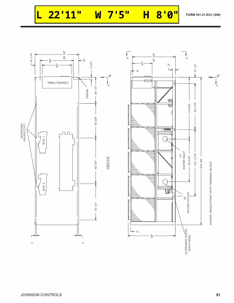
FORM 201.21-EG1 (209)
81Johnson controls