modelando chuby
TRANSCRIPT
Modeling a Low-Polygon Character
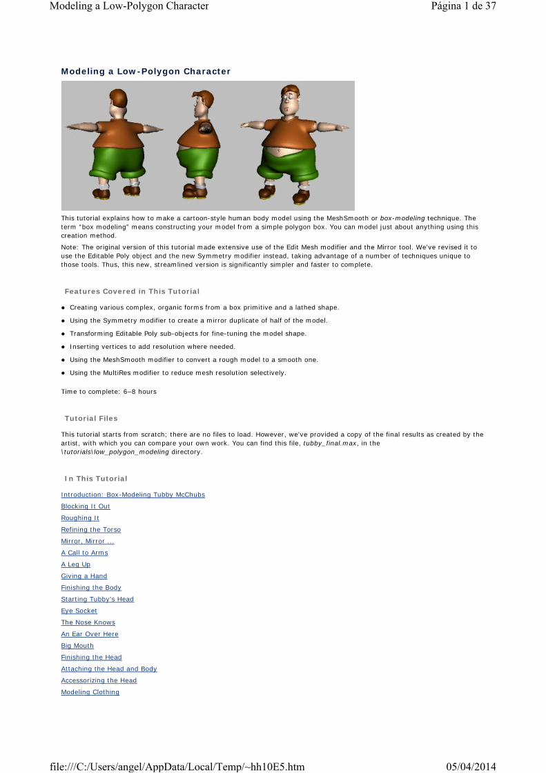
This tutorial explains how to make a cartoon-style human body model using the MeshSmooth or box-modeling technique. The term “box modeling” means constructing your model from a simple polygon box. You can model just about anything using this creation method.
Note: The original version of this tutorial made extensive use of the Edit Mesh modifier and the Mirror tool. We've revised it to use the Editable Poly object and the new Symmetry modifier instead, taking advantage of a number of techniques unique to those tools. Thus, this new, streamlined version is significantly simpler and faster to complete.
Features Covered in This Tutorial
Creating various complex, organic forms from a box primitive and a lathed shape.
Using the Symmetry modifier to create a mirror duplicate of half of the model.
Transforming Editable Poly sub-objects for fine-tuning the model shape.
Inserting vertices to add resolution where needed.
Using the MeshSmooth modifier to convert a rough model to a smooth one.
Using the MultiRes modifier to reduce mesh resolution selectively.
Time to complete: 6–8 hours
Tutorial Files
This tutorial starts from scratch; there are no files to load. However, we've provided a copy of the final results as created by the artist, with which you can compare your own work. You can find this file, tubby_final.max, in the \tutorials\low_polygon_modeling directory.
In This Tutorial
Introduction: Box-Modeling Tubby McChubs
Blocking It Out
Roughing It
Refining the Torso
Mirror, Mirror ...
A Call to Arms
A Leg Up
Giving a Hand
Finishing the Body
Starting Tubby's Head
Eye Socket
The Nose Knows
An Ear Over Here
Big Mouth
Finishing the Head
Attaching the Head and Body
Accessorizing the Head
Modeling Clothing
Página 1 de 37Modeling a Low-Polygon Character
05/04/2014file:///C:/Users/angel/AppData/Local/Temp/~hh10E5.htm
Comments
Introduction: Box-Modeling Tubby McChubs
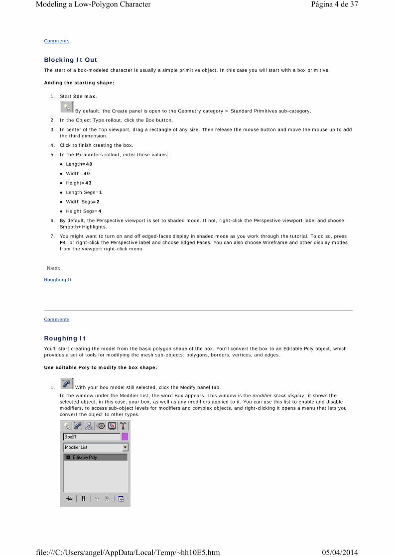
Throughout the history of 3D software, polygon modeling has been a fundamental method of building objects. It's simple, quick, and relatively easy to implement. The traditional drawback is that models tend to look angular and non-organic. More advanced methods such as patch modeling and NURBS have risen in popularity as they became increasingly available in 3D applications. These modeling methods let users do what has been difficult with polygon modeling: create smooth models that are relatively fast and easy to work with.
More recently, the implementation of innovative tools such as MeshSmooth and Subdivision Surfaces has resulted in a revival of polygon modeling. These newer tools and methods let you take advantage of the speed of polygons and the wealth of available high-level tools, but now offer the added ability to end up with smooth models. The techniques involved in polygon/smooth modeling are similar to the "rough-refine" technique traditionally trained modelers might already be familiar with. You can take a rough shape, similar to a block of clay, and then add details and refine the model in desired areas. This allows the model to be detailed in complex regions without wasting data in other areas.
The benefits of polygon modeling include simple but powerful tools that are fast and easy to use, as well as the ability to combine models seamlessly without too much work, or worrying about issues like tangency or blends, found in NURBS. They also allow easy animation setup. You can take the low-resolution version of the model and "skin" it for animation, instead of having to use a high-detail model.
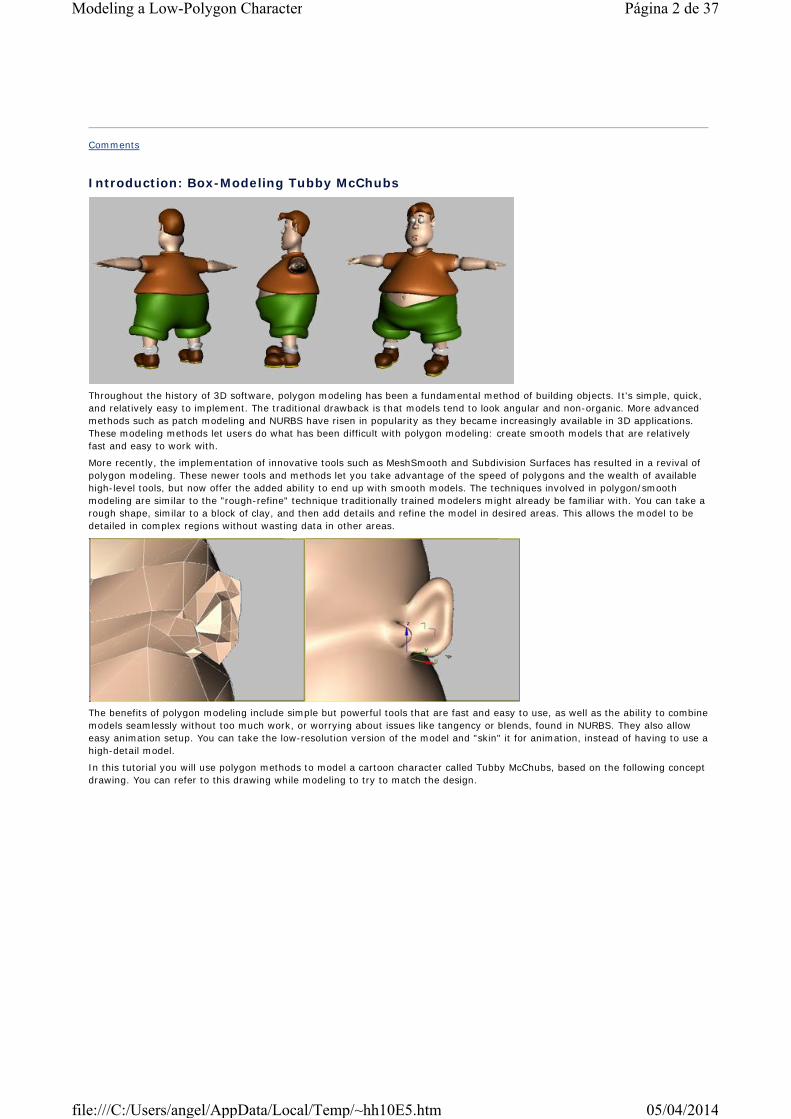
In this tutorial you will use polygon methods to model a cartoon character called Tubby McChubs, based on the following concept drawing. You can refer to this drawing while modeling to try to match the design.
Página 2 de 37Modeling a Low-Polygon Character
05/04/2014file:///C:/Users/angel/AppData/Local/Temp/~hh10E5.htm

Getting Around
A note about viewport navigation: You can follow most of this tutorial more easily if you work in a Perspective or User viewport. You can enable and disable shading and edged-faces displays by right-clicking the viewport label or using hot keys; by default, these are F2 and F4.
You can use three basic tools to obtain an appropriate view of the model:
To move around the viewport, use the Pan tool. Click the Pan button at the bottom of the screen that looks like a hand. You can then drag in the viewport to move the view around vertically and horizontally. When you are finished, right-click to exit Pan mode. Alternatively, if you have a three-button or wheel mouse, press and hold the middle or wheel button to temporarily activate Pan mode.
To zoom the view, use the Zoom tool, which looks like a magnifying glass. In Zoom mode, drag in the viewport to zoom in and out, and right-click to exit. With a wheel mouse, rotate the wheel to zoom.
To rotate the view around the model, use the Arc Rotate tool. The button has a circle with the axis arrows pointing out of it. The button image shown here is yellow, indicating that it is set to rotate around the sub-object selection. With a three-button or wheel mouse, press and hold ALT+the middle or wheel button to temporarily activate the current Arc Rotate navigation mode.
The Arc Rotate flyout
This button is on a flyout, as indicated by the small triangle in the icon button's lower-right corner. This means you can click and hold down the left mouse button on the icon to bring up different versions of the tool. The flyout choices are Arc Rotate, Arc Rotate Selected, and Arc Rotate Sub-object.
For this tutorial, we recommend using Arc Rotate Sub-object, so that rotations in the viewport occur around whatever is selected in sub-object level, such as polygons, vertices, or edges.
Next
Blocking It Out
Página 3 de 37Modeling a Low-Polygon Character
05/04/2014file:///C:/Users/angel/AppData/Local/Temp/~hh10E5.htm
Comments
Blocking It OutThe start of a box-modeled character is usually a simple primitive object. In this case you will start with a box primitive.
Adding the starting shape:
1. Start 3ds max.
By default, the Create panel is open to the Geometry category > Standard Primitives sub-category.
2. In the Object Type rollout, click the Box button.
3. In center of the Top viewport, drag a rectangle of any size. Then release the mouse button and move the mouse up to add the third dimension.
4. Click to finish creating the box.
5. In the Parameters rollout, enter these values:
Length=40
Width=40
Height=43
Length Segs=1
Width Segs=2
Height Segs=4
6. By default, the Perspective viewport is set to shaded mode. If not, right-click the Perspective viewport label and choose Smooth+Highlights.
7. You might want to turn on and off edged-faces display in shaded mode as you work through the tutorial. To do so, press F4, or right-click the Perspective label and choose Edged Faces. You can also choose Wireframe and other display modes from the viewport right-click menu.
Next
Roughing It
Comments
Roughing ItYou'll start creating the model from the basic polygon shape of the box. You'll convert the box to an Editable Poly object, which provides a set of tools for modifying the mesh sub-objects: polygons, borders, vertices, and edges.
Use Editable Poly to modify the box shape:
1. With your box model still selected, click the Modify panel tab.
In the window under the Modifier List, the word Box appears. This window is the modifier stack display; it shows the selected object, in this case, your box, as well as any modifiers applied to it. You can use this list to enable and disable modifiers, to access sub-object levels for modifiers and complex objects, and right-clicking it opens a menu that lets you convert the object to other types.
Página 4 de 37Modeling a Low-Polygon Character
05/04/2014file:///C:/Users/angel/AppData/Local/Temp/~hh10E5.htm
2. Right-click the modifier stack display, and from the right-click menu, under Convert To:, choose Editable Poly.
The Editable Poly object lets you work with the sub-object components that make up the mesh model: vertex, edge, border, polygon, and element.
3. Expand the sub-object hierarchy for the Editable Poly object by clicking the + icon to its left in the stack display, and then click the Vertex label.
This places you at the Vertex sub-object level, so you can work on the vertices in the model. The modifier's Vertex sub-object level is highlighted in yellow in the stack display.
The box model's vertices appear in the viewports as blue dots.
Next, you'll manipulate vertices to mold the model into a torso shape.
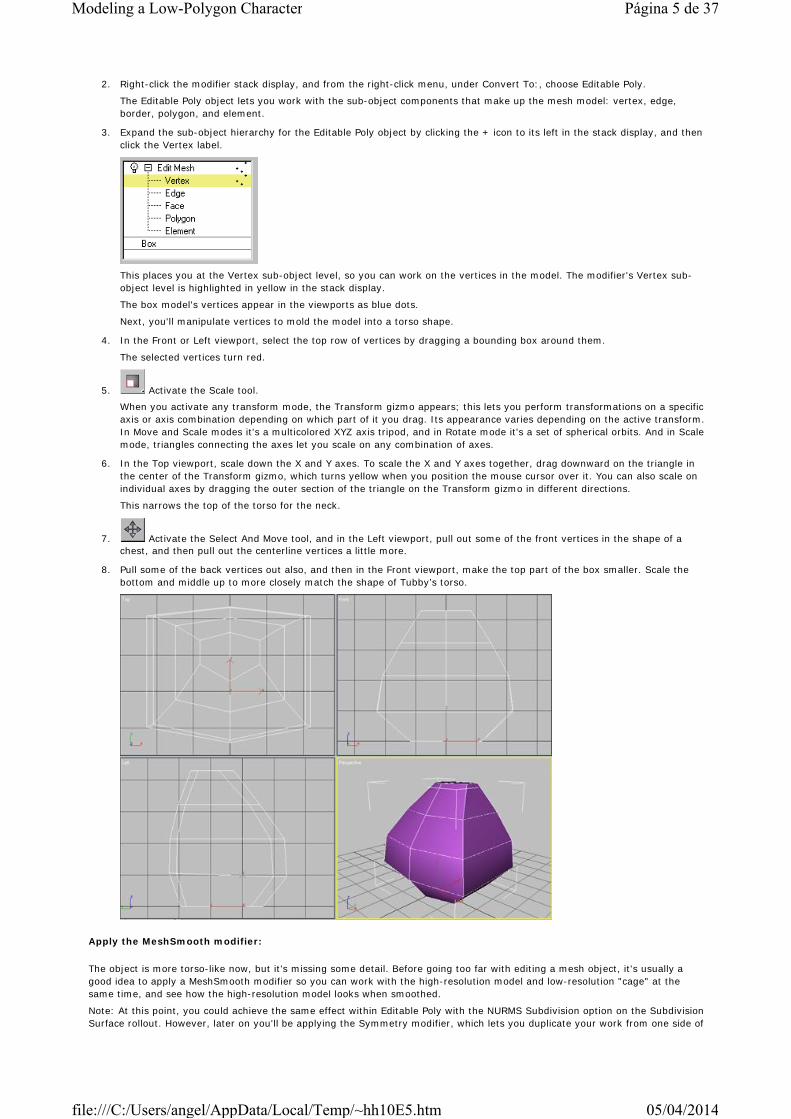
4. In the Front or Left viewport, select the top row of vertices by dragging a bounding box around them.
The selected vertices turn red.
5. Activate the Scale tool.
When you activate any transform mode, the Transform gizmo appears; this lets you perform transformations on a specific axis or axis combination depending on which part of it you drag. Its appearance varies depending on the active transform. In Move and Scale modes it's a multicolored XYZ axis tripod, and in Rotate mode it's a set of spherical orbits. And in Scale mode, triangles connecting the axes let you scale on any combination of axes.
6. In the Top viewport, scale down the X and Y axes. To scale the X and Y axes together, drag downward on the triangle in the center of the Transform gizmo, which turns yellow when you position the mouse cursor over it. You can also scale on individual axes by dragging the outer section of the triangle on the Transform gizmo in different directions.
This narrows the top of the torso for the neck.
7. Activate the Select And Move tool, and in the Left viewport, pull out some of the front vertices in the shape of a chest, and then pull out the centerline vertices a little more.
8. Pull some of the back vertices out also, and then in the Front viewport, make the top part of the box smaller. Scale the bottom and middle up to more closely match the shape of Tubby’s torso.
Apply the MeshSmooth modifier:
The object is more torso-like now, but it's missing some detail. Before going too far with editing a mesh object, it's usually a good idea to apply a MeshSmooth modifier so you can work with the high-resolution model and low-resolution "cage" at the same time, and see how the high-resolution model looks when smoothed.
Note: At this point, you could achieve the same effect within Editable Poly with the NURMS Subdivision option on the Subdivision Surface rollout. However, later on you'll be applying the Symmetry modifier, which lets you duplicate your work from one side of
Página 5 de 37Modeling a Low-Polygon Character
05/04/2014file:///C:/Users/angel/AppData/Local/Temp/~hh10E5.htm
the mesh to the other. Using the Editable Poly smoothing function would force the Symmetry modifier to do extra work and could introduce rendering artifacts, but applying MeshSmooth as a modifier lets Symmetry work before the smoothing is done, giving improved results with less computation required.
1. With the model selected, exit the sub-object level by clicking Vertex in the stack display.
Tip: You can also toggle sub-object levels by clicking the icon buttons at the top of the Selection rollout.
2. Open the Modifier List at the top of the Modify panel and choose Object-Space Modifers > MeshSmooth.
3. In the Subdivision Amount rollout, change the Iterations setting to 2.
The model appears in a smoothed state. You can raise or lower this setting to add more or less detail to your model. A setting of 2 is adequate for most models. When animating, you can get faster feedback by lowering the Iterations setting and raising the Render Iterations setting so that the model renders more smoothly than it appears in the viewport.
4. Save your work by choosing File menu > Save and specifying a file name.
It's a good idea to save periodically as you work through this tutorial. Also, after the first save, you can save consecutively numbered versions by choosing File menu > Save As and clicking the + button in the Save File As dialog.
Next
Refining the Torso
Comments
Refining the TorsoIn this topic you'll add more detail to the torso and adjust the vertices so that you can easily add arms to the character.
On each of the model's four height segments, there is only one large polygon from front to back. You could extrude the arm from that, but it is too big; in addition, you will want some more detail from front to back on the model to help round it out. You could have provided this detail by adding an extra segment when you created the box. But you've already converted the box to Editable Poly, thus losing access to the creation parameters, so you’ll instead use the Slice tool to add the detail in just the right place.
Modify the torso shape:
1. Select the torso object if it is not already selected.
In the modifier stack display, the Editable Poly hierarchy should still be expanded.
2. In the modifier stack display, click Editable Poly > Edge.
This moves you back to the base-object level, and you see the low-resolution version of the model before MeshSmooth takes effect.
You might need to toggle the Show End Result On/Off Toggle button to the off state in order to see the low-resolution version.
3. In the Edit Geometry rollout, click the Slice Plane button.
The Slice Plane gizmo appears as an orange wireframe square on the torso model representing the slicing plane.
The Slice Plane tool uses a square gizmo to define a 2D cutting plane. Where this plane intersects your model, the model is cut or divided and new edges and vertices appear. It’s important to note that the cutting plane defined by the gizmo extends infinitely in all directions. Even if the gizmo is small, it will still cut through your entire model.
In its default position, the gizmo is horizontal through the object center, but you'll be making a vertical cut. You could rotate and move the gizmo into place, but it's easier to do the initial setup with the new QuickSlice tool. Then you'll use Slice Plane to make the actual slice.
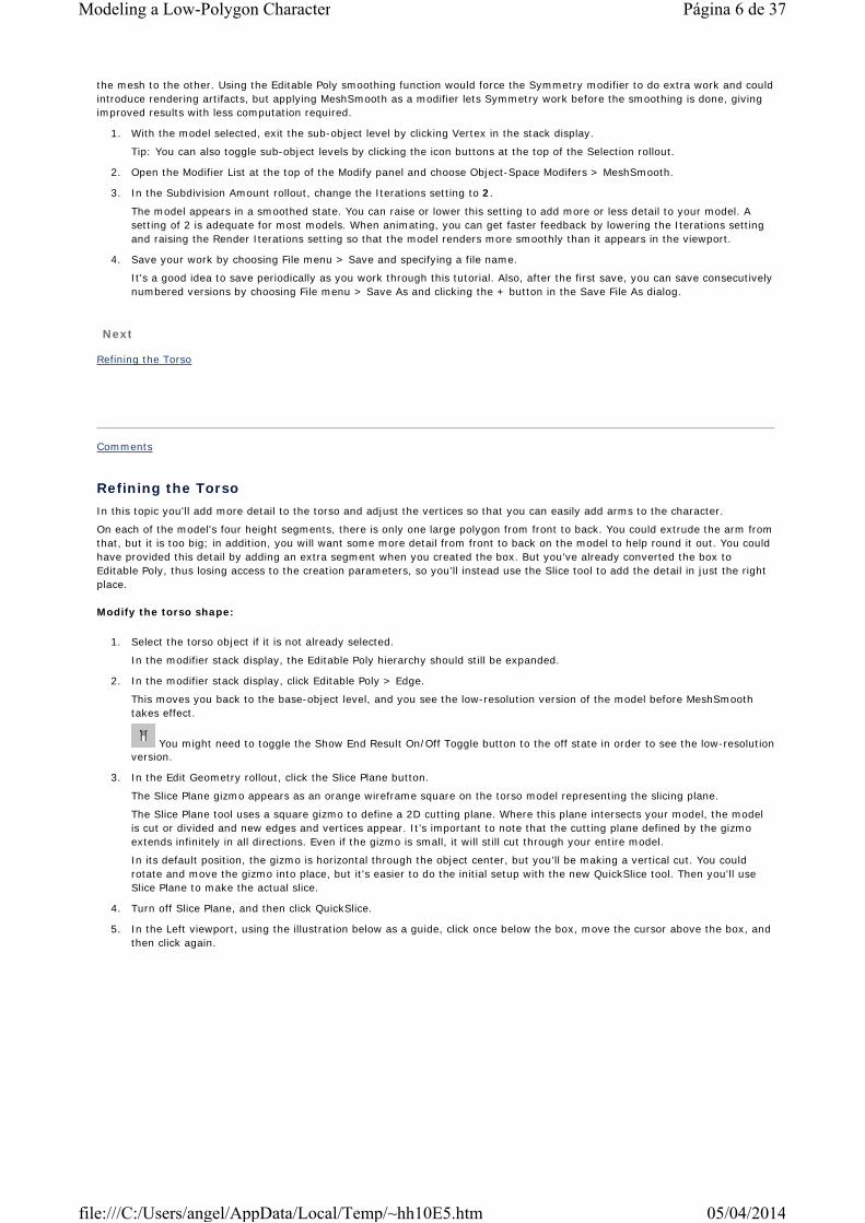
4. Turn off Slice Plane, and then click QuickSlice.
5. In the Left viewport, using the illustration below as a guide, click once below the box, move the cursor above the box, and then click again.
Página 6 de 37Modeling a Low-Polygon Character
05/04/2014file:///C:/Users/angel/AppData/Local/Temp/~hh10E5.htm

As you move the cursor after the first click, a line dynamically shows you where QuickSlice will create new edges.
6. Press CTRL+z to undo the QuickSlice, and then click Slice Plane.
The Slice Plane gizmo appears where the QuickSlice was.
7. If necessary, move and rotate the gizmo so it's positioned as shown in the following illustration.
8. When you are done adjusting the position of the gizmo, click the Slice button to create the new edges, and then click the Slice Plane button to exit the tool.
9. Go to the Vertex sub-object level, deselect all vertices by clicking in an empty area of the active viewport, and then return to the Edge level.
Add detail to the arm polygon:
You will use the top-rear polygon to extrude an arm. The four sides of this polygon aren't enough to produce a nicely rounded arm. You'll add a vertex to the bottom edge of the arm polygon, increasing it to five sides.
You should still be at the Edge sub-object level.
1. In the Edit Edges rollout, click the Insert Vertex button.
2. Click the middle of the bottom edge of the arm polygon. The following illustration shows where to insert the vertex.
A new vertex appears where you click.
3. Go to Vertex sub-object level.
Página 7 de 37Modeling a Low-Polygon Character
05/04/2014file:///C:/Users/angel/AppData/Local/Temp/~hh10E5.htm
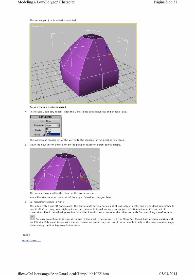
The vertex you just inserted is selected.
Torso with new vertex inserted
4. In the Edit Geometry rollout, click the Constraints drop-down list and choose Face.
This constrains movement of the vertex to the plane(s) of the neighboring faces.
5. Move the new vertex down a bit so the polygon takes on a pentagonal shape.
The vertex moves within the plane of the lower polygon.
You will make the arm come out of the upper five-sided polygon later.
6. Set Constraints back to None.
This effectively turns off Constraints. The Constraints setting persists at all sub-object levels, and if you don't remember to turn it off after using, you might get unexpected results transforming a sub-object selection using a different set of constraints. Read the following section for a brief introduction to some of the other methods for controlling transformation.
Because MeshSmooth is now at the top of the stack, you can turn off the Show End Result button when working with the Editable Poly mesh to see with the low-resolution model only, or turn it on to be able to adjust the low-resolution cage while seeing the final high-resolution mesh.
Next
Mirror, Mirror ...
Página 8 de 37Modeling a Low-Polygon Character
05/04/2014file:///C:/Users/angel/AppData/Local/Temp/~hh10E5.htm

Comments
Mirror, Mirror ...You’ve set up the start of the left-arm area, but the right side is not finished. Rather than duplicating these and later steps on each side, you’ll split the model into two parts, deleting the right side. Then you'll apply the new Symmetry modifier, which mirrors the left side and automatically attaches the two sides to make a complete model. By working on half of the model and then mirroring it over, you’ll have less to do, and the model will be symmetrical.
Create a mirror image of half of the torso:
1. Access the Polygon sub-object level of the Editable Poly object.
2. If necessary, turn off the Selection rollout > Ignore Backfacing option so as to be able to select all polygons, not just ones facing you.
3. In the Front viewport, select all the polygons on the model’s right side (the left side of the viewport). This is the side without the extra vertex.
4. Press the DELETE key to delete all the polygons on that side of the model.
5. When asked "Delete Isolated Vertices?", click the Yes button.
6. Exit sub-object level.
7. From the Modifier List > Object-Space Modifiers category, choose Symmetry.
Because the Editable Poly was highlighted in the stack, the Symmetry modifier is added between Editable Poly and MeshSmooth. This lets Symmetry work directly on the low-poly mesh, requiring less computation than if it were above MeshSmooth.
You should now see your model mirrored over to the other side. It should be centered properly, but if it isn't, adjust the Symmetry modifier's Mirror sub-object to move it as needed, or turn on Flip.
Página 9 de 37Modeling a Low-Polygon Character
05/04/2014file:///C:/Users/angel/AppData/Local/Temp/~hh10E5.htm

8. Save your work.
The Symmetry modifier creates a mirrored instance of the object it's applied to, eliminates any overlapping geometry, and welds the vertices where the two halves meet. Any changes you make to original side of the model, including adding new modifiers and adjusting sub-objects, are automatically mirrored onto the side created by the Symmetry modifier, so you can see how the complete model would look.
To test this, go to Editable Poly Vertex sub-object level, turn on the Show End Result toggle, and move some vertices around on the original side. As you make changes to the object, the mirrored side mimics your actions, keeping the meshes symmetrical. Be sure to undo any test modifications you make before continuing. Use the Edit menu > Undo command to undo changes.
Tip: When working at the sub-object level with an Editable Poly object to which the Symmetry modifier has been applied, an orange wireframe cage appears around the original half if Show End Result is turned on. If you prefer not to see this cage, go to the bottom of the Edit Geometry rollout and turn off Show Cage.
Next
A Call to Arms
Comments
A Call to ArmsYou'll leave the torso for a moment, and start to create some arms for the character. You'll do this by taking the five-sided polygon you just set up, and extend it with the Extrude function. Extrude takes a sub-object selection and pulls it into the third dimension.
Start the arms:
1. Select the object, if necessary, and then go to the Editable Poly > Polygon sub-object level.
2. Activate Select And Move, if necessary, and then select the pentagonal five-sided polygon on the side of the model.
This will become the arm.
Página 10 de 37Modeling a Low-Polygon Character
05/04/2014file:///C:/Users/angel/AppData/Local/Temp/~hh10E5.htm
On the Edit Geometry rollout, there are two buttons. One is labeled Extrude and the other Bevel. Each has a Settings button next to it.
You'll use Bevel, which combines extrusion with a scaling or “outlining” step.
3. Click the Bevel Settings button to open the Bevel Polygons dialog.
The dialog opens with Height set to the default of 10, creating an instant extrusion that will serve as a starting point for the arm.
For the remaining steps in this lesson, use the next illustration (near the end of the lesson) as a guide.
4. Change the Height setting to about 2. Accept the default Outline amount of -1, and click Ok to apply the settings and close the dialog.
5. Use the Select And Move tool to transform this new polygon so that the top surface is flat.
As a general rule, make the first extrusion for a limb, close to the torso, a short one. This gives you some detail that you can use when setting up the character for animation.
6. Click the Bevel button.
The button highlights.
7. Drag with the left mouse button on the new end polygon. As you drag, the polygon is extruded in or out. When you are happy with the result, release the left mouse button. Next, move the mouse vertically. As it moves, the polygon is now scaled up and down. When you are happy with the size, click once more to end the bevel operation.
In this way, you can extrude and scale with one operation. When you are done, click the Bevel button or right-click in the active viewport to exit Bevel mode.
8. Continue building the arm shape, using the Extrude and Bevel tools and the Move and Rotate tools to adjust the polygons.
9. You might also scale the polygon in the Front viewport on the X axis to flatten it. This will allow you to extrude or bevel straight out sideways. You will probably find that initial extrusions take place at an angle upwards. This is because the polygon is extruded along its surface normal, perpendicular to its surface. If you flatten the polygon along the X axis after the first or second extrusion, then it will extrude outwards along that axis only.
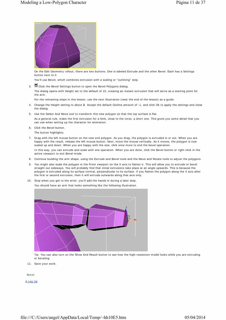
10. Stop when you get to the wrist; you’ll add the hands in during a later step.
You should have an arm that looks something like the following illustration.
Tip: You can also turn on the Show End Result button to see how the high-resolution model looks while you are extruding or beveling.
11. Save your work.
Next
A Leg Up
Página 11 de 37Modeling a Low-Polygon Character
05/04/2014file:///C:/Users/angel/AppData/Local/Temp/~hh10E5.htm

Comments
A Leg UpThe body is starting to look good. You'll now add the legs from the torso down to the ankle. You can stop at the ankle area because the character's shoes will cover its feet.
You'll use the same methods for creating the leg as for the arm. You’ll select the bottom polygons at the angle on the bottom side of the torso, and extrude/bevel out several times.
Create the leg:
1. You should still be at the Polygon sub-object level.
2. Select the two angled polygons halfway between the side and bottom of the torso.
3. Use the Extrude and Bevel techniques mixed with moving and rotating the polygons, as covered in the previous lesson, to create the leg. Try to end up with a leg that looks like the following illustration.
4. When you get to the knee area, extrude two or three sections close together, so that when you set the character up to animate, it will deform properly.
5. Continue by adjusting the middle edges and vertices to pull them out so the leg is more rounded, and also adjusting the vertices where the leg hits the body to make this area look more natural. The finished leg should look similar to the illustration.
Extrude the neck:
You'll also create part of the neck.
1. Select the top-rear polygon and extrude or bevel it upwards.
Before the Symmetry modifier, this would have created an additional polygon that lay on the centerline of the character, which you would have had to delete. Using Symmetry makes this unnecessary.
Página 12 de 37Modeling a Low-Polygon Character
05/04/2014file:///C:/Users/angel/AppData/Local/Temp/~hh10E5.htm

2. Adjust vertices as desired to create the neck shape. You might also move and adjust vertices on the torso now to tweak the shape a little.
Note: The centerline vertices at the top of the neck are created by the Symmetry modifier; to transform them, you must either turn off Show End Result or turn on Show Cage.
3. Exit sub-object level when done and save your work.
Next
Giving a Hand
Comments
Giving a HandYou’re almost done with Tubby’s body. The only major component missing now is the hand. You'll create the hand similarly to the arms and legs. Once again, you’ll select some polygons at the end of the wrist and extrude fingers. You'll first add more detail to the model so you can make two fingers. Using only two fingers makes your work easier and creates a more cartoon-like character.
Start the hand:
1. Select the polygon at the end of the arm and extrude it out to create the length of the palm of the hand.
You’ll extrude the fingers out of this polygon. But currently you have just one large polygon. If you want to extrude two fingers, you’ll need to cut it in two to make a left polygon for the index finger and a right polygon for the pinky.
You'll do this by dividing the top edge. You already have a point on the bottom of the five-sided polygon. You will divide the top edge to add a new point, making it a six-sided polygon.
2. Go to the Edge sub-object level.
3. Click the Edit Edges rollout > Insert Vertex button.
4. Click the top flat edge at the end of the hand.
A new vertex appears where you click.
If you don't see the vertex, turn off the Show End Result On/Off Toggle button.
5. Go to Vertex sub-object level.
The vertex you just inserted is selected.
6. Move the new vertex up a little bit to make the shape hexagonal.
Connect the vertices:
You'll use the Connect command to connect the top and bottom vertices.
1. Select the vertices at the centers of the upper and lower edges.
2. Click the Edit Vertices rollout > Connect button.
You now have two polygons at the end of the hand, as shown. This way you can extrude the fingers individually.
Página 13 de 37Modeling a Low-Polygon Character
05/04/2014file:///C:/Users/angel/AppData/Local/Temp/~hh10E5.htm

Extruding the fingers:
Now you'll make the fingers and thumb, again by extruding or beveling polygons.
1. Go to Polygon sub-object level.
2. Select one of the finger polygons.
Important: Extrude each separately, so that you produce discrete fingers. If you selected both together, you’d just get one large chunk.
3. Use the Extrude and Bevel tools to make the finger. Be sure to add a little extra detail in the knuckles area so they can bend nicely when set up for animation.
You should end up with something like the following illustration. You might also want to adjust some of the vertices in the finger and hand to make the shape more rounded.
4. Perform the same series of extrusions and bevels to create the pinky finger.
5. Select the polygon on the side of the hand and extrude the thumb from it.
6. Adjust the vertices on the thumbs and fingers until you are satisfied with the general look.
You should end up with something like the following illustration:
7. At this point, you can continue to add more detail and refinements using the tools learned so far. Try adding a Slice in
Página 14 de 37Modeling a Low-Polygon Character
05/04/2014file:///C:/Users/angel/AppData/Local/Temp/~hh10E5.htm

front of the wrist to add one more segment before the hand starts to help with wrist setup. You might want to divide the palm area or cut it to give more definition to the thumb base. You can also slice, cut, or add more edges to the fingers to make them five- or six-sided polygons instead of extruded squares.
In the following illustration, the modeler added a wrist slice, cut the bottom of the thumb and palm into multiple sections, and moved vertices around for more detail.
8. Exit sub-object level when done and save your work.
Next
Finishing the Body
Comments
Finishing the BodyThe body is essentially complete. The main task that remains is to join the left and right halves together. You’ll do this by collapsing most of the stack for the right side, then mirroring, attaching, and welding the other half on.
Collapse the stack:
1. In the stack display, click the Symmetry modifier.
2. Right-click the Symmetry modifier, and from the menu, choose Collapse To. If the Warning dialog appears, click Yes to continue.
This “bakes” the modifier's effect into the Editable Poly object, so that the entire body is now editable, rather than just the left half.
The stack now contains only two items: MeshSmooth on top and Editable Poly on the bottom. In the previous step, you kept all your work, but collapsed it so the object no longer contains a separate modifiers. Once you're satisfied with your object, use this "cleanup" step to save memory, speed up object interaction, and make the stack display more readable.
Adding a navel:
The last body part you'll add is the bellybutton.
1. Select the Editable Poly entry in the stack.
2. Go to Vertex sub-object level.
3. Select the vertex in the center-front stomach area.
You'll start the bellybutton here.
4. On the Edit Vertices rollout, click the Chamfer Settings button next to the Chamfer button. In the Chamfer Vertices dialog, increase the Chamfer Amount setting to 1.4.
This replaces the vertex with a square diamond. The Chamfer tool is useful for adding a ring around selected vertices, as well as outlining edges, as you'll see shortly.
You now have a polygon for the bellybutton that you can extrude and bevel for the indentation.
5. Go to Polygon sub-object level.
Página 15 de 37Modeling a Low-Polygon Character
05/04/2014file:///C:/Users/angel/AppData/Local/Temp/~hh10E5.htm
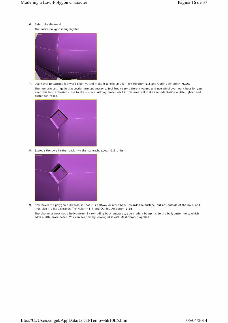
6. Select the diamond.
The entire polygon is highlighted.
7. Use Bevel to extrude it inward slightly, and make it a little smaller. Try Height=-0.2 and Outline Amount=-0.16.
The numeric settings in this section are suggestions; feel free to try different values and use whichever work best for you. Keep this first extrusion close to the surface. Adding more detail in this area will make the indentation a little tighter and better controlled.
8. Extrude the poly farther back into the stomach, about -1.6 units.
9. Now bevel the polygon outwards so that it is halfway or more back towards the surface, but not outside of the hole, and then size it a little smaller. Try Height=1.4 and Outline Amount=-0.16
The character now has a bellybutton. By extruding back outwards, you made a bump inside the bellybutton hole, which adds a little more detail. You can see this by looking at it with MeshSmooth applied.
Página 16 de 37Modeling a Low-Polygon Character
05/04/2014file:///C:/Users/angel/AppData/Local/Temp/~hh10E5.htm
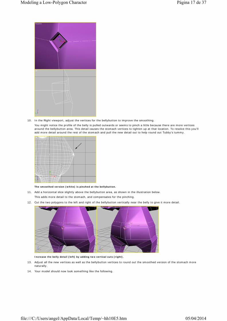
10. In the Right viewport, adjust the vertices for the bellybutton to improve the smoothing.
You might notice the profile of the belly is pulled outwards or seems to pinch a little because there are more vertices around the bellybutton area. This detail causes the stomach vertices to tighten up at that location. To resolve this you'll add more detail around the rest of the stomach and pull the new detail out to help round out Tubby's tummy.
The smoothed version (white) is pinched at the bellybutton.
11. Add a horizontal slice slightly above the bellybutton area, as shown in the illustration below.
This adds more detail to the stomach, and compensates for the pinching.
12. Cut the two polygons to the left and right of the bellybutton vertically near the belly to give it more detail.
Increase the belly detail (left) by adding two vertical cuts (right).
13. Adjust all the new vertices as well as the bellybutton vertices to round out the smoothed version of the stomach more naturally.
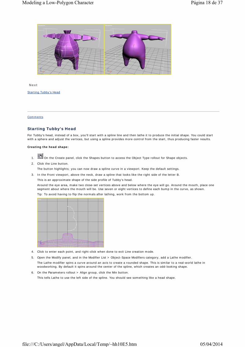
14. Your model should now look something like the following.
Página 17 de 37Modeling a Low-Polygon Character
05/04/2014file:///C:/Users/angel/AppData/Local/Temp/~hh10E5.htm
Next
Starting Tubby's Head
Comments
Starting Tubby's HeadFor Tubby’s head, instead of a box, you’ll start with a spline line and then lathe it to produce the initial shape. You could start with a sphere and adjust the vertices, but using a spline provides more control from the start, thus producing faster results.
Creating the head shape:
1. On the Create panel, click the Shapes button to access the Object Type rollout for Shape objects.
2. Click the Line button.
The button highlights; you can now draw a spline curve in a viewport. Keep the default settings.
3. In the Front viewport, above the neck, draw a spline that looks like the right side of the letter B.
This is an approximate shape of the side profile of Tubby’s head.
Around the eye area, make two close-set vertices above and below where the eye will go. Around the mouth, place one segment about where the mouth will be. Use seven or eight vertices to define each bump in the curve, as shown.
Tip: To avoid having to flip the normals after lathing, work from the bottom up.
4. Click to enter each point, and right-click when done to exit Line creation mode.
5. Open the Modify panel, and in the Modifier List > Object-Space Modifiers category, add a Lathe modifier.
The Lathe modifier spins a curve around an axis to create a rounded shape. This is similar to a real-world lathe in woodworking. By default it spins around the center of the spline, which creates an odd-looking shape.
6. On the Parameters rollout > Align group, click the Min button.
This tells Lathe to use the left side of the spline. You should see something like a head shape.
Página 18 de 37Modeling a Low-Polygon Character
05/04/2014file:///C:/Users/angel/AppData/Local/Temp/~hh10E5.htm
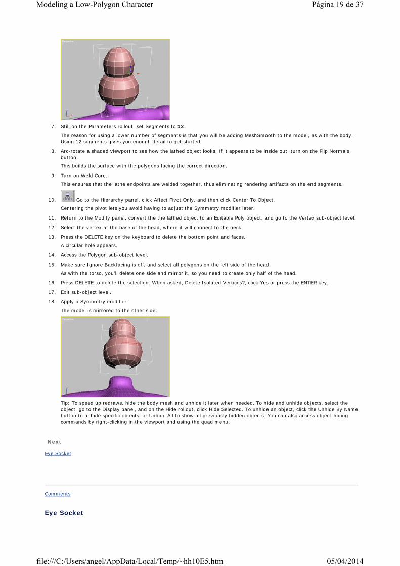
7. Still on the Parameters rollout, set Segments to 12.
The reason for using a lower number of segments is that you will be adding MeshSmooth to the model, as with the body. Using 12 segments gives you enough detail to get started.
8. Arc-rotate a shaded viewport to see how the lathed object looks. If it appears to be inside out, turn on the Flip Normals button.
This builds the surface with the polygons facing the correct direction.
9. Turn on Weld Core.
This ensures that the lathe endpoints are welded together, thus eliminating rendering artifacts on the end segments.
10. Go to the Hierarchy panel, click Affect Pivot Only, and then click Center To Object.
Centering the pivot lets you avoid having to adjust the Symmetry modifier later.
11. Return to the Modify panel, convert the the lathed object to an Editable Poly object, and go to the Vertex sub-object level.
12. Select the vertex at the base of the head, where it will connect to the neck.
13. Press the DELETE key on the keyboard to delete the bottom point and faces.
A circular hole appears.
14. Access the Polygon sub-object level.
15. Make sure Ignore Backfacing is off, and select all polygons on the left side of the head.
As with the torso, you’ll delete one side and mirror it, so you need to create only half of the head.
16. Press DELETE to delete the selection. When asked, Delete Isolated Vertices?, click Yes or press the ENTER key.
17. Exit sub-object level.
18. Apply a Symmetry modifier.
The model is mirrored to the other side.
Tip: To speed up redraws, hide the body mesh and unhide it later when needed. To hide and unhide objects, select the object, go to the Display panel, and on the Hide rollout, click Hide Selected. To unhide an object, click the Unhide By Name button to unhide specific objects, or Unhide All to show all previously hidden objects. You can also access object-hiding commands by right-clicking in the viewport and using the quad menu.
Next
Eye Socket
Comments
Eye Socket
Página 19 de 37Modeling a Low-Polygon Character
05/04/2014file:///C:/Users/angel/AppData/Local/Temp/~hh10E5.htm

You’ll build the eye by extruding polygons inward, making an eye socket. You’ll also add detail at that area so you can sculpt the eye socket to be more rounded.
Create the eye socket:
1. Select the head object, and go to the Editable Poly > Polygon sub-object level.
You'll add two vertical slices to the model around the eye area.
2. Select the four polygons from the area just above the eye section, down and including one polygon onto the lower face.
The illustration below shows which polygons to select.
3. Use QuickSlice or Slice Plane to divide the polygons vertically, a third of the way in from the left side.
Select these polygons (left) and add a vertical slice (right).
Next, you'll subdivide the upper and lower edges of the eye polygon. You'll end up with a six-sided polygon, which lets you make the eye shape more rounded.
4. Go to Edge sub-object level, click Insert Vertex, and click the centers of the upper and lower edges of the polygons to add a vertex to each. The following illustration shows where to insert the vertices.
At this point, you have the necessary detail around the eyes. You’ll turn the eye polygons into more of a rounded shape, and then extrude them inwards, as with the bellybutton.
5. Go to Vertex sub-object level and move the vertices forming the eye polygon into a hexagonal arrangement.
Finish the eyes:
1. Go to Polygon sub-object mode and select the eye polygon
2. Bevel and extrude the polygons back into the head.
Make the two initial bevels close to the front surface of the head so that you can use them as eyelids. Then extrude farther in once more to create the socket. You might also extrude a short distance more than the first two times, and then make them go back, but also scale up to create a true lip or roundness for the eyelid area if you want. It’s up to you how much detail you want to work with. It should look something like this illustration when done.
Página 20 de 37Modeling a Low-Polygon Character
05/04/2014file:///C:/Users/angel/AppData/Local/Temp/~hh10E5.htm
3. Exit sub-object level.
4. Apply a MeshSmooth modifier to your head object and set Iterations to 2 to see the model smoothed.
Create an eyeball:
It’s a good idea to create an eyeball object to make sure that your eyelid is shaped correctly. You’ll add a sphere, position it inside of the socket, and adjust the head mesh to make it fit.
1. Go to Create panel > Geometry and click the Sphere button.
2. In any viewport, drag out a sphere primitive.
3. Use the Select And Move tool to place the sphere inside the area of the eye socket.
4. Go to the Modify panel, where you'll see the basic options for the sphere you created.
5. Adjust the Radius setting as needed until the sphere's size more closely matches the eyelid and socket area. Also, lower the Segments setting to 24.
6. Select the head mesh.
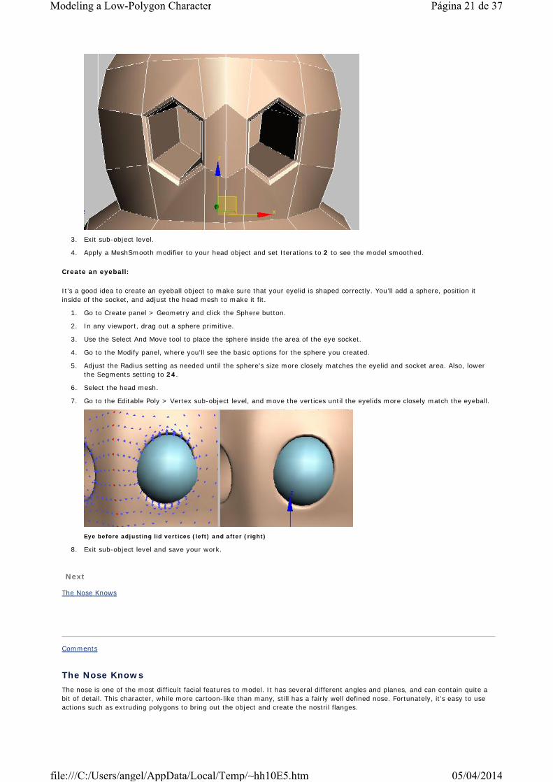
7. Go to the Editable Poly > Vertex sub-object level, and move the vertices until the eyelids more closely match the eyeball.
Eye before adjusting lid vertices (left) and after (right)
8. Exit sub-object level and save your work.
Next
The Nose Knows
Comments
The Nose KnowsThe nose is one of the most difficult facial features to model. It has several different angles and planes, and can contain quite a bit of detail. This character, while more cartoon-like than many, still has a fairly well defined nose. Fortunately, it’s easy to use actions such as extruding polygons to bring out the object and create the nostril flanges.
Página 21 de 37Modeling a Low-Polygon Character
05/04/2014file:///C:/Users/angel/AppData/Local/Temp/~hh10E5.htm
Build the nose:
1. Turn off the MeshSmooth modifier (click the light bulb icon in its stack entry) and go to the Editable Poly > Polygon sub-object level.
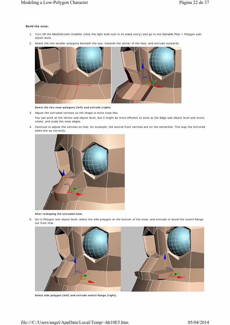
2. Select the two smaller polygons beneath the eye, towards the center of the face, and extrude outwards.
Select the two nose polygons (left) and extrude (right).
3. Adjust the extruded vertices so the shape is more nose-like.
You can work at the Vertex sub-object level, but it might be more efficient to work at the Edge sub-object level and move, rotate, and scale the nose edges.
4. Continue to adjust the vertices so that, for example, the central front vertices are on the centerline. This way the mirrored sides line up correctly.
After reshaping the extruded nose
5. Go to Polygon sub-object level, select the side polygon on the bottom of the nose, and extrude or bevel the nostril flange out from that.
Select side polygon (left) and extrude nostril flange (right).
Página 22 de 37Modeling a Low-Polygon Character
05/04/2014file:///C:/Users/angel/AppData/Local/Temp/~hh10E5.htm
6. Rotate the view to look underneath the nose at the bottom two polygons. Use the Cut tool to cut a new edge across both from left to right, effectively making a cross in the bottom middle of the nose.
The new vertex in the bottom center of the nose will become the nostril hole. You'll use the Chamfer tool on it to make a polygon to extrude inwards, as with the bellybutton.
7. Go to the Vertex sub-object level and select the vertex at the bottom center of the nose.
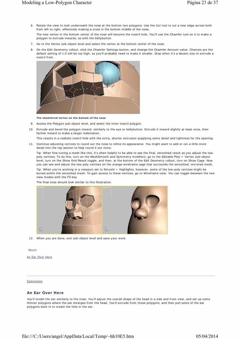
8. On the Edit Geometry rollout, click the Chamfer Settings button, and change the Chamfer Amount value. Chances are the default setting of 1.0 will be too high, so you'll probably need to make it smaller. Stop when it’s a decent size to extrude a nostril from.
The chamfered vertex on the bottom of the nose
9. Access the Polygon sub-object level, and select the inner nostril polygon.
10. Extrude and bevel the polygon inward, similarly to the eye or bellybutton. Extrude it inward slightly at least once, then farther inward to make a larger indentation.
This results in a realistic nostril hole with the extra, shorter extrusion supplying some detail and tightness for the opening.
11. Continue adjusting vertices to round out the nose to refine its appearance. You might want to add or cut a little more detail into the top section to help round it out more.
Tip: When fine-tuning a mesh like this, it's often helpful to be able to see the final, smoothed result as you adjust the low-poly vertices. To do this, turn on the MeshSmooth and Symmetry modifiers, go to the Editable Poly > Vertex sub-object level, turn on the Show End Result toggle, and then, at the bottom of the Edit Geometry rollout, turn on Show Cage. Now you can see and adjust the low-poly vertices on the orange wireframe cage that surrounds the smoothed, mirrored mesh.
Tip: When you're working in a viewport set to Smooth + Highlights, however, some of the low-poly vertices might be buried within the smoothed mesh. To gain access to these vertices, go to Wireframe view. You can toggle between the two view modes with the F3 key.
The final nose should look similar to this illustration.
12. When you are done, exit sub-object level and save your work.
Next
An Ear Over Here
Comments
An Ear Over HereYou'll model the ear similarly to the nose. You’ll adjust the overall shape of the head in a side and front view, and set up some thinner polygons where the ear emerges from the head. You’ll extrude from those polygons, and then pull some of the ear polygons back in to create the hole in the ear.
Página 23 de 37Modeling a Low-Polygon Character
05/04/2014file:///C:/Users/angel/AppData/Local/Temp/~hh10E5.htm

1. Select the head model if it is not already selected.
2. Go to the Vertex sub-object level.
Looking at the model from the side, notice that there are one or two large polygons towards the center of the head. This would be a good place to extrude an ear from, but currently they are too wide.
3. Adjust the vertices to make the polygons thinner so that you can use them to extrude the ear.
4. Continue adjusting vertices in the Left and Front viewports to make the head shape more natural looking and closer to the concept drawing.
5. Access the Polygon sub-object level and select the two smaller polygons on the side of the head.
6. Extrude these polygons outward once.
7. Scale the polygons smaller in the Front viewport on the X axis.
This flattens them so you can get a straighter extrusion.
8. Extrude and/or bevel two or three more times to get the general ear shape.
Shown here are three ear extrusions: once close to the sides of the head, a second for the center of the ear, and a third farther out and scaled in for the edge.
9. Adjust the vertices on the ear to give it a more natural ear shape, pulling up on the outer edge of the top and down on the lobe. Give it a little curve in a side view.
The ear is missing the notch that comes out at the point where it meets the head surface.
10. Select the middle point where the ear meets the surface, and chamfer it to create a new polygon diamond.
Página 24 de 37Modeling a Low-Polygon Character
05/04/2014file:///C:/Users/angel/AppData/Local/Temp/~hh10E5.htm

Select point (left) and chamfer (right)
11. At the Polygon sub-object level, select the new diamond-shaped polygon, and then extrude and bevel it out to create the ear wedge.
12. Adjust the vertices to give the extrusion a more natural shape.
13. Chamfer the vertex that is behind the wedge toward the inner ear, and then extrude that new polygon back into the head to make the ear hole.
Select vertex on back of wedge (left) and chamfer (right).
Select the new diamond polygon (left) and extrude back into the head (right).
14. Continue to refine the ear by cutting polygons and adjusting vertices on the main ear shape to add more detail.
You can also use Insert Vertex to cut edges and, at the Vertex sub-object level, you can use the new Remove command to get rid of incorrect vertices without welding. The following illustration shows a few more cuts into the ear for a nice ridge around the edge, as in the concept drawing.
15. When you are satisfied with the ear, select all the ear vertices. In the Top viewport, rotate the selection backwards so it lies more closely along the surface of the head. The final ear is shown here.
Página 25 de 37Modeling a Low-Polygon Character
05/04/2014file:///C:/Users/angel/AppData/Local/Temp/~hh10E5.htm
16. When you are done, exit sub-object level and save your work.
Next
Big Mouth
Comments
Big MouthThe mouth is similar to just about every indentation you’ve modeled. You’ll use Chamfer to create lip-shaped edges, then extrude the inside mouth inward, and the lips outward.
Model the mouth:
1. Select the head object if it is not already selected, and go to the Vertex sub-object level. Turn off the MeshSmooth modifier if necessary.
Notice how, under the nose, there is one row of horizontal edges. You’ll keep those so that the nose isn’t affected too much when the mouth moves.
Lower down is another row of edges. You’ll create the mouth around that area.
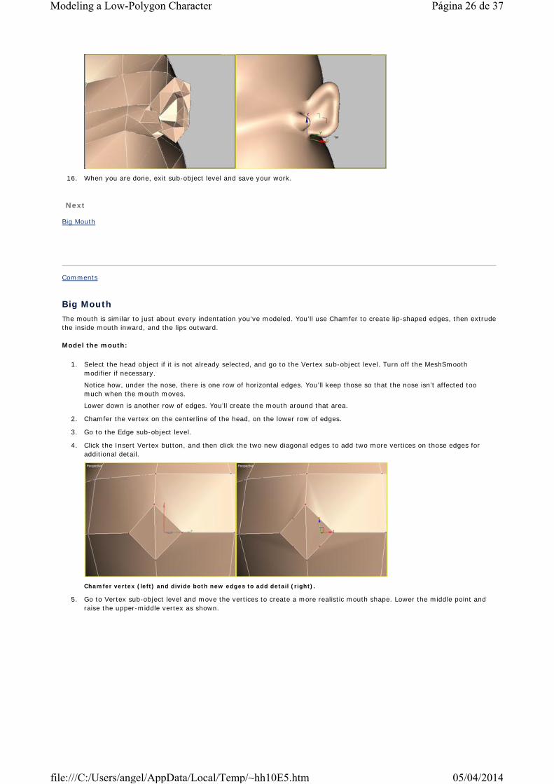
2. Chamfer the vertex on the centerline of the head, on the lower row of edges.
3. Go to the Edge sub-object level.
4. Click the Insert Vertex button, and then click the two new diagonal edges to add two more vertices on those edges for additional detail.
Chamfer vertex (left) and divide both new edges to add detail (right).
5. Go to Vertex sub-object level and move the vertices to create a more realistic mouth shape. Lower the middle point and raise the upper-middle vertex as shown.
Página 26 de 37Modeling a Low-Polygon Character
05/04/2014file:///C:/Users/angel/AppData/Local/Temp/~hh10E5.htm
6. Go to the Edge sub-object level.
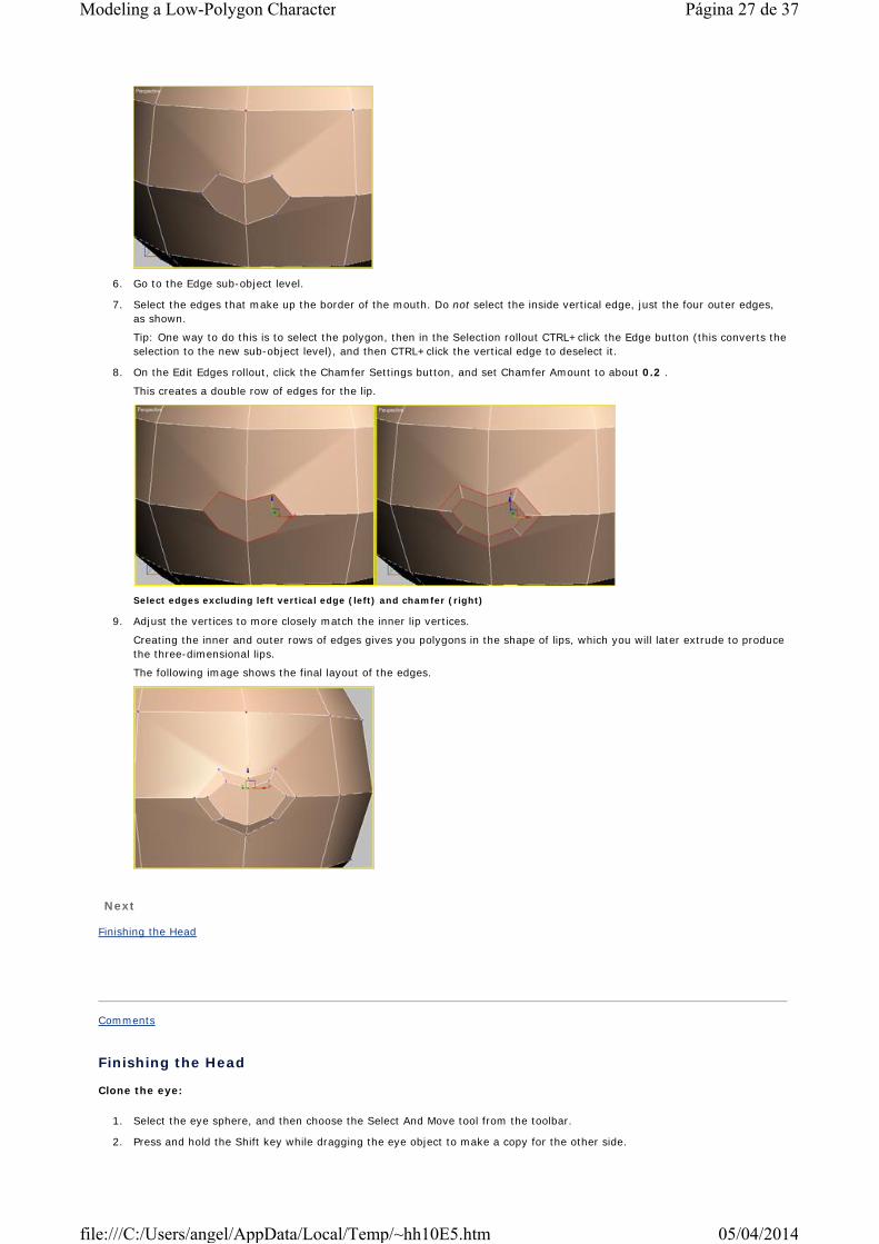
7. Select the edges that make up the border of the mouth. Do not select the inside vertical edge, just the four outer edges, as shown.
Tip: One way to do this is to select the polygon, then in the Selection rollout CTRL+click the Edge button (this converts the selection to the new sub-object level), and then CTRL+click the vertical edge to deselect it.
8. On the Edit Edges rollout, click the Chamfer Settings button, and set Chamfer Amount to about 0.2 .
This creates a double row of edges for the lip.
Select edges excluding left vertical edge (left) and chamfer (right)
9. Adjust the vertices to more closely match the inner lip vertices.
Creating the inner and outer rows of edges gives you polygons in the shape of lips, which you will later extrude to produce the three-dimensional lips.
The following image shows the final layout of the edges.
Next
Finishing the Head
Comments
Finishing the Head
Clone the eye:
1. Select the eye sphere, and then choose the Select And Move tool from the toolbar.
2. Press and hold the Shift key while dragging the eye object to make a copy for the other side.
Página 27 de 37Modeling a Low-Polygon Character
05/04/2014file:///C:/Users/angel/AppData/Local/Temp/~hh10E5.htm

When you release the mouse button, a dialog appears asking how the copy (clone) should be made.
3. Keep the default settings so it is a true copy and click OK.
Complete the mouth:
1. Select the head model if it is not already selected.
2. On the Modify panel > modifier stack display, right-click the Symmetry entry and, from the right-click menu, choose Collapse To.
The entire head is now a unified mesh. This will make it easier to finish modeling the mouth.
3. Go to the Edge level, and select the vertical edge at the center of the mouth-hole polygon.
4. On the Edit Edges rollout, click Remove.
The two inner mouth polygons are combined into one.
Next, you'll select and extrude the polygons that make up the lips; this is the ring around the mouth-hole polygon.
5. Access the Polygon sub-object level.
You'll use the new Grow feature to select the eight lip polygons without having to click each one. There are other ways to accomplish this, but one of the purposes of this tutorial is to introduce you to new features in 3ds max 5.
6. Select the mouth-hole polygon.
7. On the Selection rollout, click the Grow button.
All the mouth polygons are now selected.
8. CTRL+click the central mouth polygon to deselect it.
9. Extrude the lips forward once as shown.
The extruded lips are split in the middle.
10. Go to Edge sub-object level, select the two inside vertical edges, and move them leftward so they meet in the center.
Currently you have a big ring for the lips, which isn’t realistic. Most lips come back and flatten out at the corner. To do this, you’ll target weld the vertices on the corners of the lips back to the surface on each side.
11. Go to the Vertex sub-object level.
12. In the Edit Vertices rollout, click the Target button.
13. Drag one of the two extruded vertices on the outside corner of the mouth back to the surface point behind it, as shown. Do the same for the inside corner vertex.
Página 28 de 37Modeling a Low-Polygon Character
05/04/2014file:///C:/Users/angel/AppData/Local/Temp/~hh10E5.htm
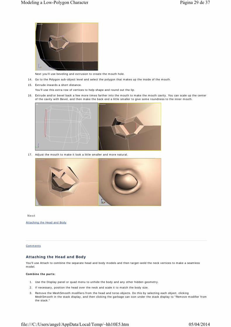
Next you'll use beveling and extrusion to create the mouth hole.
14. Go to the Polygon sub-object level and select the polygon that makes up the inside of the mouth.
15. Extrude inwards a short distance.
You'll use this extra row of vertices to help shape and round out the lip.
16. Extrude and/or bevel back a few more times farther into the mouth to make the mouth cavity. You can scale up the center of the cavity with Bevel, and then make the back end a little smaller to give some roundness to the inner mouth.
17. Adjust the mouth to make it look a little smaller and more natural.
Next
Attaching the Head and Body
Comments
Attaching the Head and BodyYou'll use Attach to combine the separate head and body models and then target-weld the neck vertices to make a seamless model.
Combine the parts:
1. Use the Display panel or quad menu to unhide the body and any other hidden geometry.
2. If necessary, position the head over the neck and scale it to match the body size.
3. Remove the MeshSmooth modifiers from the head and torso objects. Do this by selecting each object, clicking MeshSmooth in the stack display, and then clicking the garbage can icon under the stack display to "Remove modifier from the stack."
Página 29 de 37Modeling a Low-Polygon Character
05/04/2014file:///C:/Users/angel/AppData/Local/Temp/~hh10E5.htm
4. You might want to delete the bottom row of vertices on Tubby’s head since it doesn’t add much detail; doing so will give the bottom of the head a wider hole.
At this point, the bottom of the head has 12 vertices, but the top of the neck has only six vertices. For a weld to work properly, however, both edges must contain the same number of vertices. To resolve this, you'll add a vertical cut into each polygon on the side of the neck, ending up with 12 vertices. That way you can line up the vertex pairs and target weld the head and neck together.
5. Select the torso model.
6. Access the Edge sub-object level.
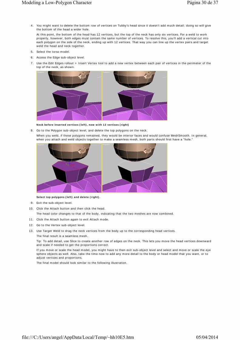
7. Use the Edit Edges rollout > Insert Vertex tool to add a new vertex between each pair of vertices in the perimeter of the top of the neck, as shown.
Neck before inserted vertices (left), now with 12 vertices (right)
8. Go to the Polygon sub-object level, and delete the top polygons on the neck.
When you weld, if these polygons remained, they would be interior faces and would confuse MeshSmooth. In general, when you attach and weld objects together to make a seamless mesh, both parts should first have a "hole."
Select top polygons (left) and delete (right).
9. Exit the sub-object level.
10. Click the Attach button and then click the head.
The head color changes to that of the body, indicating that the two meshes are now combined.
11. Click the Attach button again to exit Attach mode.
12. Go to the Vertex sub-object level.
13. Use Target Weld to drag the neck vertices from the body up to the corresponding head vertices.
The final result is a seamless mesh.
Tip: To add detail, use Slice to create another row of edges on the neck. This lets you move the head vertices downward and scale if needed to get the proportions correct.
If you move or scale the head model, you might have to then exit sub-object level and select and move or scale the eye sphere objects as well. Also, take the time now to add any more detail to the body or head model that you want, or to adjust vertices and proportions.
The final model should look similar to the following illustration.
Página 30 de 37Modeling a Low-Polygon Character
05/04/2014file:///C:/Users/angel/AppData/Local/Temp/~hh10E5.htm

14. Save your work.
Optional: Lower the resolution selectively:
At this point, you have a character model with two resolutions: very low, without the MeshSmooth modifier, and relatively high, with the MeshSmooth modifier. What if you want to keep the smoothed look, but lower the polygon count? In situations like this, the MultiRes modifier can come in handy.
If you're going to animate Tubby, you need to retain high resolution in the parts that will move: the joints and around the mouth. Fortunately, MultiRes lets you specify areas in which resolution should not be reduced.
1. Select the object, and in the Modify panel > modifier stack display, click the MeshSmooth modifier.
2. From the Modifier List > Object-Space Modifiers category, apply a MultiRes modifier.
3. In the modifier stack display, expand the MultiRes hierarchy, and click Vertex to go to that sub-object level.
You can now see and select vertices on the smoothed mesh. However, you can't transform them; these vertices are for use by the MultiRes modifier settings.
4. Select all vertices in areas that should retain full resolution: the mouth, shoulders, elbows, knees, and where the legs connect to the torso.
Tip: With areas that don't fit neatly into a rectangle or circle, such as the shoulders, you might want to try region-selecting with the new Lasso Selection Region tool. This lets you drag the outline, and is faster than using Fence Selection Region.
5. On the MultiRes Parameters rollout > Generation Parameters group, turn on Maintain Base Vertices.
6. Click the Generate button.
The selected vertices dots are replaced with asterisks, to show that they are now to be protected from resolution reduction. These are maintained even if you deselect the vertices.
7. Lower the Vert Percent or Vert Count settings.
The overall mesh resolution is reduced, but the base vertices are maintained. Even if you go as low as 20 percent, the object is still recognizable, while the protected areas retain full resolution.
Next
Accessorizing the Head
Comments
Accessorizing the HeadThe head is almost complete, but is still missing teeth, gums, and eyebrows. You can add the eyebrows as a texture, or model a basic box shape with a few segments, and then move the vertices to make eyebrows, as shown here.
Most of these objects can start as simple boxes with a few segments. The gums can be a box with vertices moved to a trapezoid
Página 31 de 37Modeling a Low-Polygon Character
05/04/2014file:///C:/Users/angel/AppData/Local/Temp/~hh10E5.htm

shape, rounded a bit and then smoothed.
The teeth can be boxes placed on the gums. For more cartoon-like teeth, you can start with a single long box object, bend it, smooth it, and then place it along the ridge of the gums.
You can make a tongue by adding a sphere primitive with a low Segments setting, flattening and lengthening it, and then smoothing it.
Lastly, you can create a simple hair object by starting with a box with several segments, and then extruding out a tuft of hair in the front, and extruding some sideburns polygons on the sides and back.
When completed, the body and head objects should look like this:
Modeling the teeth, tongue, eyebrows, and hair with MeshSmooth lets you attach these objects to the head. That is, you can remove the MeshSmooth modifiers so that all objects are low resolution. Then you can combine them all into a single mesh object with the Edit Mesh > Attach function. You don’t need to weld vertices.
You can still select each component at the Element sub-object level. You can texture them using a multi/sub-object material. One reason you might want the head parts to be combined into a single mesh is that if the character is set up with morph targets for facial animation, all of the inner mouth or eyebrow objects are part of the same morph target. So, they will automatically move the right way once the targets are created.
If you don’t want to attach the objects together, you can still simplify showing a high-resolution or low-resolution version by first removing the MeshSmooth modifier from each of the objects. Then select all the objects and apply a MeshSmooth modifier. This lets you raise and lower the Iterations setting with any one object selected and affect all the objects, because they're instances of the same MeshSmooth modifier.
Página 32 de 37Modeling a Low-Polygon Character
05/04/2014file:///C:/Users/angel/AppData/Local/Temp/~hh10E5.htm
Next
Modeling Clothing
Comments
Modeling ClothingAll that remains to add are clothing objects. You can make most items by adding a box primitive with several segments, and adjusting and extruding its sub-objects. With some clothing items, it's easier to start with a spline line, as with the head, and then lathe or extrude that.
The rest of this tutorial serves as an overview, showing one possibility for how to start the model, and then showing a progression and how the final piece was completed. You can use all of the tools and methods covered up to this point, including Editable Poly, Slice Plane and QuickSlice, Cut, Remove, Target Weld, Extrude, and Bevel, to create the rest of the objects.
Create the socks:
For the socks, you'll use a box just because it is easier to show a method for creating holes in clothing, such as where the feet go into the sock. Ordinarily you would probably create socks by lathing a spline.
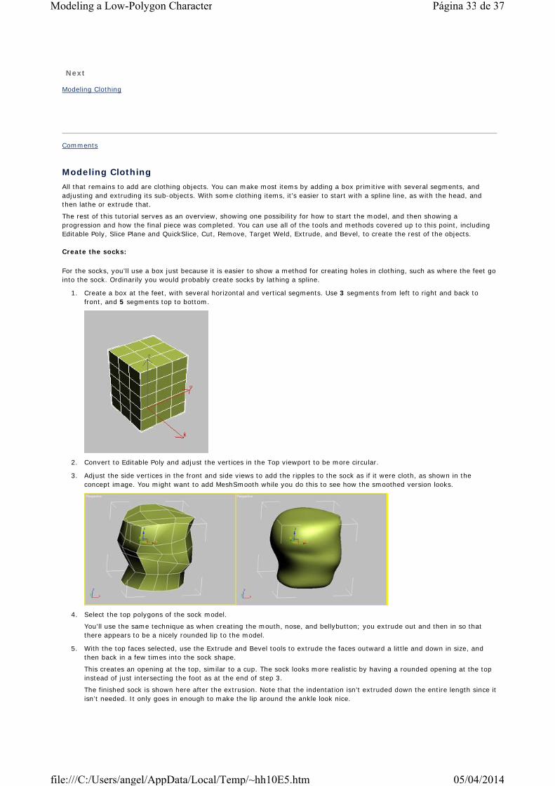
1. Create a box at the feet, with several horizontal and vertical segments. Use 3 segments from left to right and back to front, and 5 segments top to bottom.
2. Convert to Editable Poly and adjust the vertices in the Top viewport to be more circular.
3. Adjust the side vertices in the front and side views to add the ripples to the sock as if it were cloth, as shown in the concept image. You might want to add MeshSmooth while you do this to see how the smoothed version looks.
4. Select the top polygons of the sock model.
You'll use the same technique as when creating the mouth, nose, and bellybutton; you extrude out and then in so that there appears to be a nicely rounded lip to the model.
5. With the top faces selected, use the Extrude and Bevel tools to extrude the faces outward a little and down in size, and then back in a few times into the sock shape.
This creates an opening at the top, similar to a cup. The sock looks more realistic by having a rounded opening at the top instead of just intersecting the foot as at the end of step 3.
The finished sock is shown here after the extrusion. Note that the indentation isn’t extruded down the entire length since it isn’t needed. It only goes in enough to make the lip around the ankle look nice.
Página 33 de 37Modeling a Low-Polygon Character
05/04/2014file:///C:/Users/angel/AppData/Local/Temp/~hh10E5.htm

6. Adjust the sock model vertices around the leg as needed. Then Shift-clone a copy to the other leg.
Create the shoes:
Start the shoes by drawing a box in a side view around the foot area and shaping the vertices to a shoe shape. Then extrude where the sock goes into the shoe, in a manner similar to creating the sock.
You can start the sole of the shoe with a box. Because there is a real change in material or object type in the real model, you can get by with creating different objects or parts of objects for the model. That is, the shoe and sole don’t have to be one seamless mesh, because in reality, they aren’t seamless. In fact, anywhere that there is a seam in a real object, you can make different pieces in your 3D model and it will still look correct.
1. Create a box for the shoe in side view. Use three main sections: one for the bump at the front and one for the back where the foot goes in.
Because you'll need to shape this box, create five segments across as shown. Use 2 segments from left to right, 3segments vertically, and 5 segments from back to front.
2. Convert to Editable Poly.
3. Scale or move the row of edges horizontally to create a double edge for each section you want.
This shows why you needed five segments, not three.
4. Also, adjust the edges vertically so there is a double edge towards the bottom.
This helps keep the bottom of the shoe flat.
5. Adjust the vertices on the model so the shoe has more of a shoe shape.
Página 34 de 37Modeling a Low-Polygon Character
05/04/2014file:///C:/Users/angel/AppData/Local/Temp/~hh10E5.htm
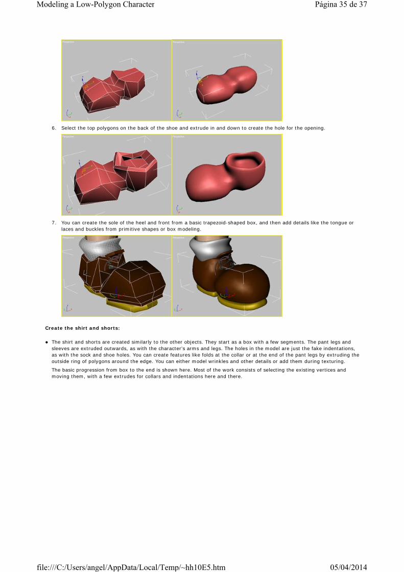
6. Select the top polygons on the back of the shoe and extrude in and down to create the hole for the opening.
7. You can create the sole of the heel and front from a basic trapezoid-shaped box, and then add details like the tongue or laces and buckles from primitive shapes or box modeling.
Create the shirt and shorts:
The shirt and shorts are created similarly to the other objects. They start as a box with a few segments. The pant legs and sleeves are extruded outwards, as with the character's arms and legs. The holes in the model are just the fake indentations, as with the sock and shoe holes. You can create features like folds at the collar or at the end of the pant legs by extruding the outside ring of polygons around the edge. You can either model wrinkles and other details or add them during texturing.
The basic progression from box to the end is shown here. Most of the work consists of selecting the existing vertices and moving them, with a few extrudes for collars and indentations here and there.
Página 35 de 37Modeling a Low-Polygon Character
05/04/2014file:///C:/Users/angel/AppData/Local/Temp/~hh10E5.htm
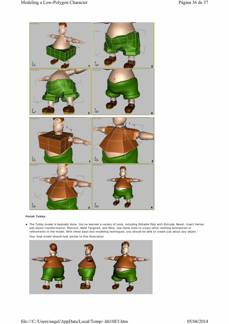
Finish Tubby:
The Tubby model is basically done. You've learned a variety of tools, including Editable Poly with Extrude, Bevel, Insert Vertex, sub-object transformation, Remove, Weld Targeted, and Slice. Use these tools to create other clothing accessories or refinements to the model. With these basic box-modeling techniques, you should be able to create just about any object.
Your final model should look similar to this illustration:
Página 36 de 37Modeling a Low-Polygon Character
05/04/2014file:///C:/Users/angel/AppData/Local/Temp/~hh10E5.htm

You'll find an example of the finished model in the file tubby_final.max on the Learning And Training CD in tutorials\lowpoly_charmodeling.
Comments
Página 37 de 37Modeling a Low-Polygon Character
05/04/2014file:///C:/Users/angel/AppData/Local/Temp/~hh10E5.htm