modeling a printed circuit heat exchanger with relap5 …/67531/metadc833229/m2/1/high... ·...
TRANSCRIPT

INL/EXT-10-20619
Modeling a Printed Circuit Heat Exchanger with RELAP5-3D for the Next Generation Nuclear Plant
Prashaanth Ravindran Piyush Sabharwall Nolan A. Anderson December 2010

DISCLAIMER This information was prepared as an account of work sponsored by an
agency of the U.S. Government. Neither the U.S. Government nor any agency thereof, nor any of their employees, makes any warranty, expressed or implied, or assumes any legal liability or responsibility for the accuracy, completeness, or usefulness, of any information, apparatus, product, or process disclosed, or represents that its use would not infringe privately owned rights. References herein to any specific commercial product, process, or service by trade name, trade mark, manufacturer, or otherwise, does not necessarily constitute or imply its endorsement, recommendation, or favoring by the U.S. Government or any agency thereof. The views and opinions of authors expressed herein do not necessarily state or reflect those of the U.S. Government or any agency thereof.

INL/EXT-10-20619
Modeling a Printed Circuit Heat Exchanger with RELAP5-3D for the Next Generation Nuclear Plant
Prashaanth Ravindran Piyush Sabharwall Nolan A. Anderson
December 2010
Idaho National Laboratory Next Generation Nuclear Plant Project
Idaho Falls, Idaho 83415
Prepared for the U.S. Department of Energy Office of Nuclear Energy
Under DOE Idaho Operations Office Contract DE-AC07-05ID14517


v
ABSTRACT
The main purpose of this report is to design a printed circuit heat exchanger (PCHE) for the Next Generation Nuclear Plant and carry out Loss of Coolant Accident (LOCA) simulation using RELAP5-3D. Helium was chosen as the coolant in the primary and secondary sides of the heat exchanger. The design of PCHE is critical for the LOCA simulations. For purposes of simplicity, a straight channel configuration was assumed. A parallel intermediate heat exchanger configuration was assumed for the RELAP5 model design. The RELAP5 modeling also required the semicircular channels in the heat exchanger to be mapped to rectangular channels. The initial RELAP5 run outputs steady state conditions which were then compared to the heat exchanger performance theory to ensure accurate design is being simulated.
An exponential loss of pressure transient was simulated. This LOCA describes a loss of coolant pressure in the primary side over a 20 second time period. The results for the simulation indicate that heat is initially transferred from the primary loop to the secondary loop, but after the loss of pressure occurs, heat transfers from the secondary loop to the primary loop.

vi

vii
ACKNOWLEDGEMENTS
The authors are thankful to Mr. Cliff B. Davis and Mr. Paul D. Bayless for their invaluable assistance and time towards this project. The authors extend their gratitude to Mike Patterson for his advice and assistance.

viii
ix
CONTENTS
ABSTRACT .................................................................................................................................................. v�
ACKNOWLEDGEMENTS ........................................................................................................................ vii�
ACRONYMS ............................................................................................................................................... xi�
NOMENCLATURE .................................................................................................................................... xi�
1.� INTRODUCTION .............................................................................................................................. 1�
2.� PARAMETERS AND ASSUMPTIONS ........................................................................................... 4�
3.� DESIGN SUMMARY ........................................................................................................................ 5�
4.� RESULTS AND DISCUSSION ......................................................................................................... 8�
5.� CONCLUSIONS AND RECOMMENDATIONS FOR FUTURE WORK ..................................... 12�
6.� REFERENCES ................................................................................................................................. 13�
Appendix A—Compact Heat Exchangers .................................................................................................. 15�
Appendix B—HeatricTM Printed Circuit Heat Exchanger .......................................................................... 19�
Appendix C—Mapping of Semicircular Channels in RELAP5-3D ........................................................... 23�
FIGURES Figure 1-1. Schematic of proposed NGNP system. ...................................................................................... 1�
Figure 3-1. Schematic of parallel IHX configuration. .................................................................................. 5�
Figure 3-2. Illustration of PCHE channels with alternating hot and cold flows with the flow path. ............ 5�
Figure 3-3. RELAP5-3D model of the PCHE. .............................................................................................. 7�
Figure 4-1. Exponential decrease in pressure at the primary loop inlet. ....................................................... 9�
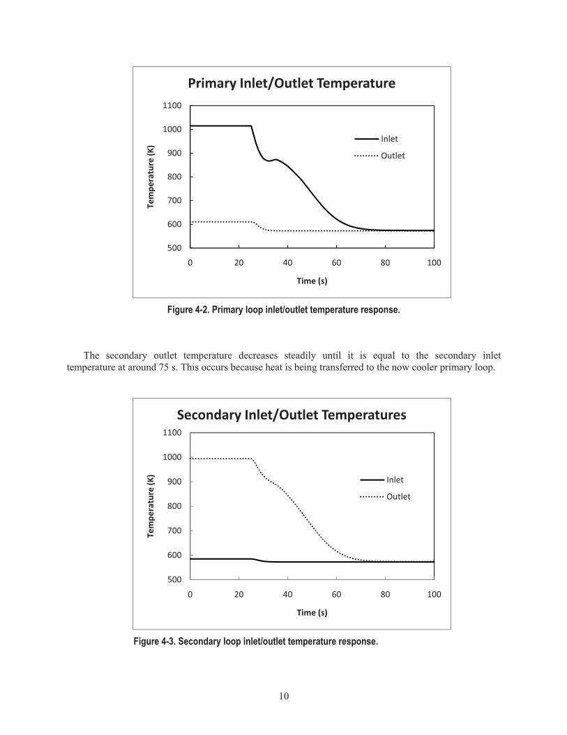
Figure 4-2. Primary loop inlet/outlet temperature response. ....................................................................... 10�
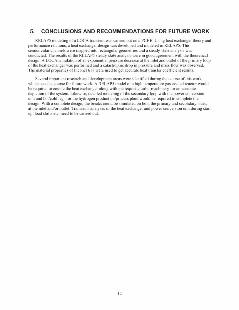
Figure 4-3. Secondary loop inlet/outlet temperature response. ................................................................... 10�
Figure 4-4. Primary loop inlet/outlet mass flow rate response. .................................................................. 11�
Figure B-1. Core of PCHE with diffusion bonded plates (Courtesy: HeatricTM). ....................................... 20�
Figure B-2. Photomicrograph of the semicircular passages (Courtesy: HeatricTM). ................................... 20�
Figure B-3. Typical PCHE configuration (Courtesy: HeatricTM). ............................................................... 21�
Figure B-4. Material properties for PCHE (ASME VIII I 2006). ............................................................... 21�
Figure C-1. Mapping a semicircular domain to a rectangular domain. ....................................................... 24�

x
TABLES Table 2-1. Key parameters and constraints. .................................................................................................. 4�
Table 4-1. Heat exchanger design. ................................................................................................................ 8�
Table 4-2. Comparison of Design and RELAP5-3D calculated point values. .............................................. 8�

xi
ACRONYMS ASME American Society of Mechanical Engineers
DOE Department Of Energy
HTE High Temperature Electrolysis
IHX Intermediate Heat Exchanger
LOCA Loss Of Coolant Accident
NGNP Next Generation Nuclear Plant
NRC Nuclear Regulatory Commission
PCHE Printed Circuit Heat Exchanger
NOMENCLATURE ACHAN Cross section area of the channel, m2
AF Free flow area, m2
AH Total heat transfer area, m2
cp Specific heat capacity at constant pressure, J/kg�K
d Channel diameter, mm
dm Rectangular mapped channel diameter, mm
DH Hydraulic diameter, mm
f Fanning friction factor
fD Darcy friction factor
h Heat transfer coefficient, W/m2�K
j Colburn friction factor
k Thermal conductivity
L Heat transfer length, m
�� Mass flow rate, kg/s
NCHAN Total number of channels
NH Number of channels along the height of the heat exchanger
NW Number of channels along the width of the heat exchanger
Nu Nusselt number
p Channel pitch, mm
P Perimeter of the channel, m
Pr Prandtl number
PIN Inlet pressure, MPa
QD Thermal duty, MWth

xii
Re Reynolds number
St Stanton number
t Plate thickness between channels, mm
teff Effective conduction thickness, mm
tm Rectangular mapped plate thickness, mm
TIN Inlet temperature, °C
TOUT Outlet temperature, °C
U Overall heat transfer coefficient, W/m2�K
V Velocity, m/s
VCHAN Volume of space taken by channels in the heat exchanger, m3
VALLOY Volume of metal in the heat exchanger, m3
Subscripts
P Primary side of the heat exchanger
S Secondary side of the heat exchanger
Greek
�� Density�
�D Maximum allowable stress, MPa
�TLM Log mean temperature difference
�pfric Frictional pressure drop, kPa
1
Modeling a Printed Circuit Heat Exchanger with RELAP5-3D for the Next Generation Nuclear Plant
1. INTRODUCTION The Next Generation Nuclear Plant (NGNP) project was initiated based on a U.S. Department of
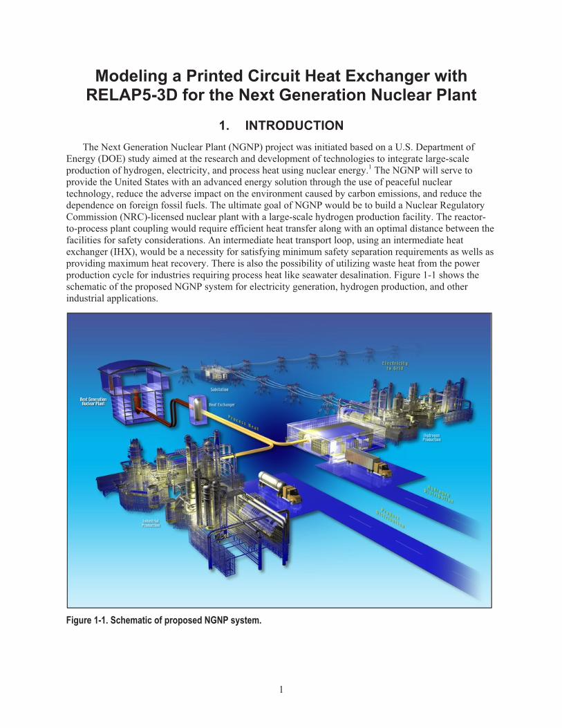
Energy (DOE) study aimed at the research and development of technologies to integrate large-scale production of hydrogen, electricity, and process heat using nuclear energy.1 The NGNP will serve to provide the United States with an advanced energy solution through the use of peaceful nuclear technology, reduce the adverse impact on the environment caused by carbon emissions, and reduce the dependence on foreign fossil fuels. The ultimate goal of NGNP would be to build a Nuclear Regulatory Commission (NRC)-licensed nuclear plant with a large-scale hydrogen production facility. The reactor-to-process plant coupling would require efficient heat transfer along with an optimal distance between the facilities for safety considerations. An intermediate heat transport loop, using an intermediate heat exchanger (IHX), would be a necessity for satisfying minimum safety separation requirements as wells as providing maximum heat recovery. There is also the possibility of utilizing waste heat from the power production cycle for industries requiring process heat like seawater desalination. Figure 1-1 shows the schematic of the proposed NGNP system for electricity generation, hydrogen production, and other industrial applications.
Figure 1-1. Schematic of proposed NGNP system.

2
The goal of NGNP is to increase energy efficiency by merging old and current technologies. Cost-effective, yet efficient and compact, heat exchangers between the nuclear plant and industrial facilities will be incorporated to maximize the transfer of energy for industrial use. The heat exchanger in question should be an equivalent Class I/Class II high-temperature component, designed in accordance with American Society of Mechanical Engineers (ASME) Boiler and Pressure Vessel Code, Sec. III. Selection of the appropriate material is paramount because the heat exchanger design will be subject to the following conditions:
� Design life of up to 60 years
� Operability in corrosive environments because of helium contamination
� Good mechanical properties: tensile strength, creep, etc.
The high temperature environment in the NGNP is challenging for many structural materials. HeatricTM recommended two materials of interest for nuclear industry: dual certified SS316/316L stainless steel and nickel-based Alloy 617.2 At present there are no NRC-approved materials for NGNP, so Alloy 617 was selected for this study.
This study investigated a new class of compact heat exchangers called printed circuit heat exchangers (PCHE) for use in the NGNP. Compact heat exchangers have high surface area density, which translates to better heat transfer and a general reduction in size.3 The compactness is achieved by the use of fins or, in the case of a PCHE, microchannels. A summary of compact heat exchangers has been presented in Appendix A.
PCHEs have been rated to operate under temperature range (from cryogenic to 900°C) and withstand pressures up to 60 MPa.4 The design of PCHEs enables them to be suitable for high purity, corrosive streams and is not susceptible to flow induced oscillations and vibrations, unlike conventional shell and tube heat exchangers. At present, HeatricTM is the world’s largest manufacturer of PCHEs, and their design specifications were chosen for this study. 5 According to HeatricTM, PCHEs require low maintenance if used in streams with particulate size limited to 300 μm. Though PCHEs have been widely used in the oil and natural gas industry in the last two decades, the nuclear power industry is yet to adopt this technology. Over the last 10 years, much of the research is centered on estimating performance because of the scarcity of available information in PCHE design. For more details on HeatricTM heat exchangers and material properties, refer to Appendix B.
The Brayton cycle with helium as the working fluid is currently the most mature of closed gas turbine cycles. Helium (He) is one of the working fluids in the intermediate heat transport loop in NGNP under strong consideration because of the following advantages:
� Low neutron cross section makes them ideal as thermal nuclear reactor coolants
� High temperature operational tolerance for efficient power generation
� Radionuclide retention under accident conditions
� Inert nature—no metal-water or metal-air reactions
� Elimination of steam cycle and high pressure steam generators by using Brayton cycle turbine
� Potential for use in nuclear waste disposal because of harder neutron energy spectrum, resulting in more effective burning of actinides
� In-service inspections are possible because of better observability, hence greater safety assurance
� Gas-cooled fast reactor studies demonstrated that during loss of forced circulation accidents, the natural circulation of helium would provide for adequate passive cooling for reactors up to 840 MWth.

3
Since there is little experience in using helium in a direct cycle application in a nuclear reactor, an extensive development program is necessary for reliability purposes.
The objectives of this study were to design and model a PCHE in RELAP5-3D and perform a loss of coolant accident (LOCA) analysis.

4
2. PARAMETERS AND ASSUMPTIONS There are two requisite primary parameters of interest for the design of an IHX between the reactor
and the secondary loop (hydrogen processing plant, seawater desalination, etc.). These are defined by the reactor outlet temperature (heat exchanger inlet) (TIN,P) and the maximum temperature delivered to the processing plant (TOUT,S). The selected reactor outlet temperature for this study was 750°C. The selected process heat temperature, which is dependent on the nature of the application, was 710°C. The temperature drop across the heat exchanger was 40°C, which is reasonable. These temperatures were selected because the efficiency of hydrogen production using high temperature electrolysis (HTE) increases with higher temperatures, and there are various HTE processes that require temperatures from 300 to 900°C. The key parameters and constraints are described in Table 2-1. The NGNP was assumed to generate a thermal duty of 600 MWth and the heat exchanger was designed to transfer the entire heat duty. Helium is used as the coolant in the reactor side (primary side of the heat exchanger) and the secondary loop. The operating pressure in the primary and secondary sides was assumed to be 8.0 and 7.73 MPa respectively, with a pressure drop constraint of less than 2% pumping pressure. Velocity constraints were imposed because of limiting the flow between laminar and laminar-turbulent transition Reynolds numbers. Though having turbulent flow in channels have shown to increase the overall heat transfer, the pressure drop increases significantly to counter any advantages from increased heat transfer.
Table 2-1. Key parameters and constraints. Parameter Constraint
Thermal duty, QD (MWth) 600 Reactor outlet temperature (heat exchanger inlet), TIN,P (°C) 750 Heat exchanger outlet temperature, TOUT,S (°C) 710 IHX primary side inlet pressure, PIN,P (MPa) 8.0 IHX secondary side inlet pressure, PIN,S (MPa) 7.73 IHX primary and secondary mass flow rate (kg/s) 282 Pressure drop constraints (primary and secondary) <2% PIN Velocity constraints (primary and secondary) (m/s) <35
Dostal previously provided a detailed component and system design for the NGNP direct Brayton power cycle.6 Gezelius had provided detailed performance comparisons and estimates of different types of heat exchangers, including PCHEs for a gas-cooled fast reactor.7 This study uses similar methodologies in getting the optimized parameters with updated correlations for calculating friction factor and Nusselt number. A direct-sizing algorithm for compact heat exchangers is currently under development.
The sizing of the heat exchangers will depend on the overall temperature difference between the outlet of the reactor core and the inlet temperature on the secondary side of the heat exchanger. The optimal design parameters used for RELAP5 modeling have been obtained from compact heat exchanger design theory detailed in Appendix A.
Davis et al. documented different plant configurations for coupling a hydrogen production facility to a nuclear reactor.8 For reasons of simplicity, a parallel IHX configuration, such as the one shown in Figure 3-1, was selected. In a parallel configuration, the fluid having the highest temperature will be directed to the power production part of the primary loop and the remainder towards the hydrogen production plant. This method achieves higher overall efficiency.
5
3. DESIGN SUMMARY
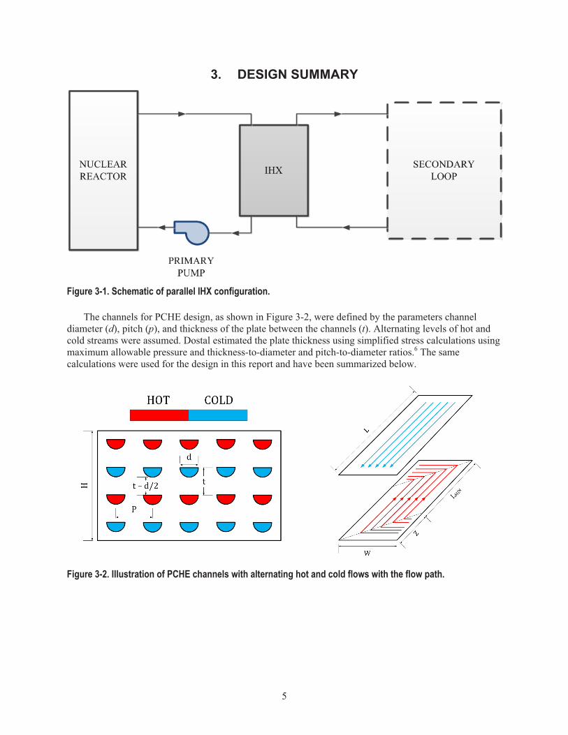
Figure 3-1. Schematic of parallel IHX configuration.
The channels for PCHE design, as shown in Figure 3-2, were defined by the parameters channel diameter (d), pitch (p), and thickness of the plate between the channels (t). Alternating levels of hot and cold streams were assumed. Dostal estimated the plate thickness using simplified stress calculations using maximum allowable pressure and thickness-to-diameter and pitch-to-diameter ratios.6 The same calculations were used for the design in this report and have been summarized below.
Figure 3-2. Illustration of PCHE channels with alternating hot and cold flows with the flow path.

6
The pitch to diameter ratio was represented as the minimum wall thickness between channels (t) and distance between the channels (p), which can be approximated as:
1D
p Pd �
�� � (2.1)
where �P is the differential pressure between the hot and cold streams and �D is the maximum allowable stress. The maximum allowable stress was taken as 10 MPa as the design stress of Inconel 617 is 12.4 MPa at temperatures greater than 898°C.9 A brief note on the HeatricTM PCHE and a comparison of high temperature alloys for possible application in NGNP is presented in Appendix B.
A RELAP5-3D model was developed and is illustrated in Figure 3-3. The model represents the heat exchanger as PIPE volumes (Components 330 and 390) connected by a heat structure (Component 1330). The PIPE component, which simulates the many small channels in the PCHE, has 40 volumes to provide detailed nodalizations for adequate convergence. Components 300 and 370 are the source volumes in the primary and secondary side respectively and are of type TMDPVOL (time-dependent volume) which provides the reactor and primary loop pressure and temperature. Components 310 and 375 are the time-dependent junctions used for controlling the mass flow rate into the system. Also, the time-dependent components set the boundary conditions of the problem, i.e., control system pressure and mass flow during steady-state calculations. To simulate a leak, the VALVE components—Components 325 and 335 on primary inlet and outlet and Components 385 and 395 on secondary inlet and outlet—can be used to connect a volume to the containment, which is at ambient conditions (Components 100, 101, 200, and 201). The flow direction was initialized as indicated in Figure 3-3 by the addition of sink TMDPVOL, which will have a pressure lower than the source. Typically, this pressure was found from the analytical calculations discussed later. The mass flow was set to 282 kg/s in the time dependent junction at the primary side inlet. Helium was used as the working fluid in the primary and secondary sides. As mentioned before, the LOCA transient was simulated only on the primary inlet side. The model has other VALVE components that will allow for future analysis. For steady-state analysis, the VALVES connecting the system to the ambient remain closed. The primary side time-dependent volumes are initialized with 8.0 MPa and 750°C in the source and 7.92 MPa and 340°C in the sink. Similarly, on the secondary side, the source was initialized to 7.73 MPa and 300°C and the sink at 7.64 MPa and 710°C. The ambient volumes were set to room temperature and pressure, simulating the containment room. The PIPE volumes were initialized with the source pressure and mass flow rate. The material properties for Inconel 617 were used for the heat structure. The thermal conduction between the primary and secondary side is multidimensional in reality, but was modeled as 1-D using rectangular geometry. The heat transfer area is the same as calculated by the analytical design. The Gnielinski heat transfer correlation was utilized on the primary and secondary side.
The LOCA was simulated by exponentially decreasing the pressure in the source and sink time-dependent volumes from the operating pressure to the ambient pressure.
In order to accurately map curved channels in RELAP5-3D which does not accept curvilinear objects, the semicircular channels have to be mapped to rectangular channels, resulting in a change in thickness of alloy between the channels. This is very important because of dependence of thermal conduction on the material thickness. The derived transformation equations are explained in detail in Appendix C.

7
Figure 3-3. RELAP5-3D model of the PCHE.

8
4. RESULTS AND DISCUSSION The heat exchanger design for use in RELAP5 was obtained using the effectiveness – number of
thermal units method explained in Appendix A. The results are tabulated in Table 4-1. The calculated pressure drop required a pumping power of 9.29 MW on the primary and secondary which would result in 1.5% of the total thermal duty. The pressure drop was almost the same in both sides because of similar operating conditions. The results are comparable to available literature.7
Table 4-1. Heat exchanger design. Parameter Values
Heat transfer length, L (m) 1.475 Channel diameter, d (mm) 1.2 Channel pitch, P (mm) 1.46 Thickness of plate, t (mm) 0.96 Total no. of channels (NCHAN) 8.7E+06 Primary side pressure drop (kPa) 81.13 Secondary side pressure drop (kPa) 81.01 Free flow area, AF (m2) 2.4623 Total heat transfer area, AH (m2) 19,813.43 Heat transfer coefficient—Primary (W/m2�K) 1,478.15 Heat transfer coefficient—Secondary (W/m2�K) 1,559.31 Overall heat transfer coefficient, U (W/m2�K) 758.82 Total Power (MW) 600
Table 4-2 compares the design values with the results of the steady-state simulation from RELAP5-
3D. The RELAP5 results show good agreement with the design calculations. The variation is ~1% of the design values, which is acceptable. The use of the Gnielinski heat transfer correlation over the default Dittus-Boelter correlation reduced the differences from 12% to less than 1%.
Table 4-2. Comparison of Design and RELAP5-3D calculated point values.
Parameter Analytical Design RELAP5-3D
Heat Duty (MW) 600 606 Primary Inlet Temperature (ºC) 750 744 Primary Outlet Temperature (ºC) 340 338 Secondary Inlet Temperature (ºC) 300 305 Secondary Outlet Temperature (ºC) 710 714 Reynolds number—Primary 2,104 2,170 Reynolds number—Secondary 2,185 2,219 Heat transfer coefficient—Primary 1,478.15 1,488.81 Heat transfer coefficient—Secondary 1,559.31 1,570.32

9
The model was next used to simulate a LOCA transient in the heat exchanger. Usually in reactors, loss of power to the pumps will result in loss of flow. Since the reactor and the secondary loop were not connected in this study, the LOCA was simulated by exponentially decreasing the pressure in the primary side of the heat exchanger.
A pipe break in the primary loop of the heat exchanger is most critical because it will result in the release of contaminants into the containment room. The break was timed to occur 25 seconds after initiation of the transient run. The primary loop pressure then exponentially decreases over the next 20 seconds until the pressure reaches ambient conditions. Figure 4-1 shows the primary loop pressure profile used to initiate the transient.
Figure 4-1. Exponential decrease in pressure at the primary loop inlet.
The helium temperature responses of the primary and secondary loops are shown in Figures 4-2 and
4-3 respectively. The primary inlet temperature decreases quickly with the loss of pressure. The small observed rise in Figure 4-2 around 35 s occurs because the primary loop temperature at the inlet decreased below the secondary loop temperature at the outlet. The primary inlet temperature then continues to decrease until it is equal to the primary outlet temperature at around 75 s.
0.00E+001.00E+062.00E+063.00E+064.00E+065.00E+066.00E+067.00E+068.00E+069.00E+06
0 10 20 30 40 50
Pressure�(P
a)
Time�(s)
Primary�Inlet�Pressure
10
Figure 4-2. Primary loop inlet/outlet temperature response.
The secondary outlet temperature decreases steadily until it is equal to the secondary inlet temperature at around 75 s. This occurs because heat is being transferred to the now cooler primary loop.
Figure 4-3. Secondary loop inlet/outlet temperature response.
500
600
700
800
900
1000
1100
0 20 40 60 80 100
Tempe
rature�(K
)
Time�(s)
Primary�Inlet/Outlet�Temperature
Inlet
Outlet
500
600
700
800
900
1000
1100
0 20 40 60 80 100
Tempe
rature�(K
)
Time�(s)
Secondary�Inlet/Outlet�Temperatures
Inlet
Outlet

11
The mass flow rate profile of the primary loop can be seen in Figure 4-4, it reflects the rapid coolant leak. After 45 s the mass flow rate has reduced nearly to 0.0 kg/s.
Figure 4-4. Primary loop inlet/outlet mass flow rate response.
The temperature inside the heat exchanger reacts to the loss of coolant at a slower pace. This was expected. Even if the coolant is completely lost, the residual heat in the heat exchanger takes longer to dissipate.
0
50
100
150
200
250
300
0 20 40 60 80 100
Mass�Flow
�Rate�(kg/s)
Time�(s)
Primary�Mass�Flow�Rate
12
5. CONCLUSIONS AND RECOMMENDATIONS FOR FUTURE WORK RELAP5 modeling of a LOCA transient was carried out on a PCHE. Using heat exchanger theory and
performance relations, a heat exchanger design was developed and modeled in RELAP5. The semicircular channels were mapped into rectangular geometries and a steady-state analysis was conducted. The results of the RELAP5 steady-state analysis were in good agreement with the theoretical design. A LOCA simulation of an exponential pressure decrease at the inlet and outlet of the primary loop of the heat exchanger was performed and a catastrophic drop in pressure and mass flow was observed. The material properties of Inconel 617 were used to get accurate heat transfer coefficient results.
Several important research and development areas were identified during the course of this work, which sets the course for future work. A RELAP5 model of a high temperature gas-cooled reactor would be required to couple the heat exchanger along with the requisite turbo-machinery for an accurate depiction of the system. Likewise, detailed modeling of the secondary loop with the power conversion unit and hot/cold legs for the hydrogen production/process plant would be required to complete the design. With a complete design, the breaks could be simulated on both the primary and secondary sides, at the inlet and/or outlet. Transients analyses of the heat exchanger and power conversion unit during start up, load shifts etc. need to be carried out.
13
6. REFERENCES 1. P. Mills, R. Soto, and G. Gibbs, Next Generation Nuclear Plant Pre-Conceptual Design Report.
INL/EXT-07-12967, Rev.1, November 2007.
2. X. Li, T. Smith, D. Kininmont, and S. J. Dewson, "Materials for Nuclear Diffusion-Bonded Compact Heat Exchangers," Proceedings of ICAPP '09, 2009, p. 9.
3. J. Hesselgreaves, Compact Heat Exchangers: Selection, Design and Rating. 1 ed. San Diego, CA, Pergamon, 2001.
4. X. Li, D. Kininmont, R. L. Pierres, S. J. Dewson, "Alloy 617 for the High Temperature Diffusion-Bonded Compact Heat Exchangers," Proceedings of ICAPP '08, 2008. p. 7.
5. X. Li, R. Le Pierres, S. Dewson, et al., "Heat exchangers for the next generation of nuclear reactors," Proceedings of the ICAPP, Vol. 6, 2006, pp.4–8.
6. V. Dostal, M. Driscoll, and P. Hejzlar, "A supercritical carbon dioxide cycle for next generation nuclear reactors. March 2004, p. 10.
7. K. Gezelius, “Design of compact intermediate heat exchangers for gas cooled fast reactors,” MIT-ANP-TR-103, May 2004.
8. C. Davis, C. Oh, R. Barner, and S. D. F. Sherman, Thermal-Hydraulic Analyses of Heat Transfer Fluid Requirements and Characteristics for Coupling a Hydrogen Production Plant to a High-Temperature Nuclear Reactor, INL/EXT-05-00453, June 2006.
9. S. Dewson and X. Li, “Selection Criteria for the High Temperature Reactor Intermediate Heat Exchanger,” Proceedings of ICAPP, Vol. 5, 2005, pp.15–19.
10. T. Kuppan, Heat Exchanger Design Handbook. Marcel Dekker, 2000.
11. W. Kays and A. London, Compact heat exchangers, New York, NY, McGraw-Hill, 1984.
12. A. Colburn, “A method of correlating forced convection heat-transfer data and a comparison with fluid friction,” International Journal of Heat and Mass Transfer, Vol. 7, Issue 12, 1964, pp. 1359-1384.
13. V. Gnielinski, “Heat transfer and pressure drop in helically coiled tubes,” Tien C, Carey V, Ferrell J, Proceedings of the Eighth International Heat Transfer Conference, Vol. 7. San Francisco, CA, Elsevier; 1986, pp. 2847–2854.
14. P. Linstrom and W. Mallard, NIST Chemistry WebBook, NIST Standard Reference Database Number 69, National Institute of Standards and Technology, Available at: http://webbook.nist.gov.

14

15
Appendix A
Compact Heat Exchangersa
a. This section has been condensed from Ref. 3, 11 and 12.
16
Appendix A Compact Heat Exchangers
The heat exchanger design balances heat transfer characteristics of the fluids with pumping requirements for fluid transfer through the heat exchanger. For liquids, this power requirement is usually small. In the case of gases, however, it is imperative to consider the pumping power a suitable design variable because it serves as an indicator for energy requirements in heat exchanger operation. This energy requirement can be high in most thermal power systems, as mechanical energy is significantly higher in the cost of thermal energy.
The velocity of fluid flow is a very important parameter in the design process, as most flow passages would show an increase in the heat transfer per surface area with an increase in fluid velocity. But the friction-to-power expenditure is also associated with an increase in fluid velocity in the form of a drop in pumping pressure; hence, a heat exchanger design is a function of heat transfer rates and pressure drop specifications.
Different types of heat exchangers—classified on the type of performance, application, operating environment, physical characteristics, etc.—are available but outside the scope of this report. Compact heat exchangers are of primary interest to be used as the intermediate heat exchanger of the NGNP because of the following specific design characteristics reported by Kuppan11:
1. High heat transfer area per unit volume of the core.
2. Small hydraulic diameter (DH).
3. Pressure drop is an important design consideration.
4. Large frontal area and a short flow length.
5. Little or no chance of fluid contamination.
6. Good for gas-to-gas applications. For preliminary design considerations, the physical dimensions may be assumed, but optimization would be necessary to ensure optimal performance. The output is usually displayed in terms of heat transfer coefficient (h), pressure drop across the heat exchanger (�P), number of thermal units (N), and pumping power (W). The analysis is performed for primary and secondary sides with the consequences of different cross-sectional areas, volume, and materials. The primary and secondary surfaces are invariably in transitional or fully turbulent Reynolds number regimes, and developed for pure counter-flow, but the analysis also works reasonably well for cross-flow. An overview of heat exchanger design is highlighted in this section. Detailed performance correlations for different types of surfaces are then explained and the complete thermal design and analysis of the printed circuit compact heat exchanger is discussed with an emphasis on optimization.
Kays and London described an approach to explain surface performance as functions of Reynolds number using Colburn friction factor j and Fanning friction factor f.12 The Colburn j factor, as first described by Colburn using a power law relationship, gives heat transfer coefficient h as a function of Prandtl number Pr, and valid for transitional flows.13
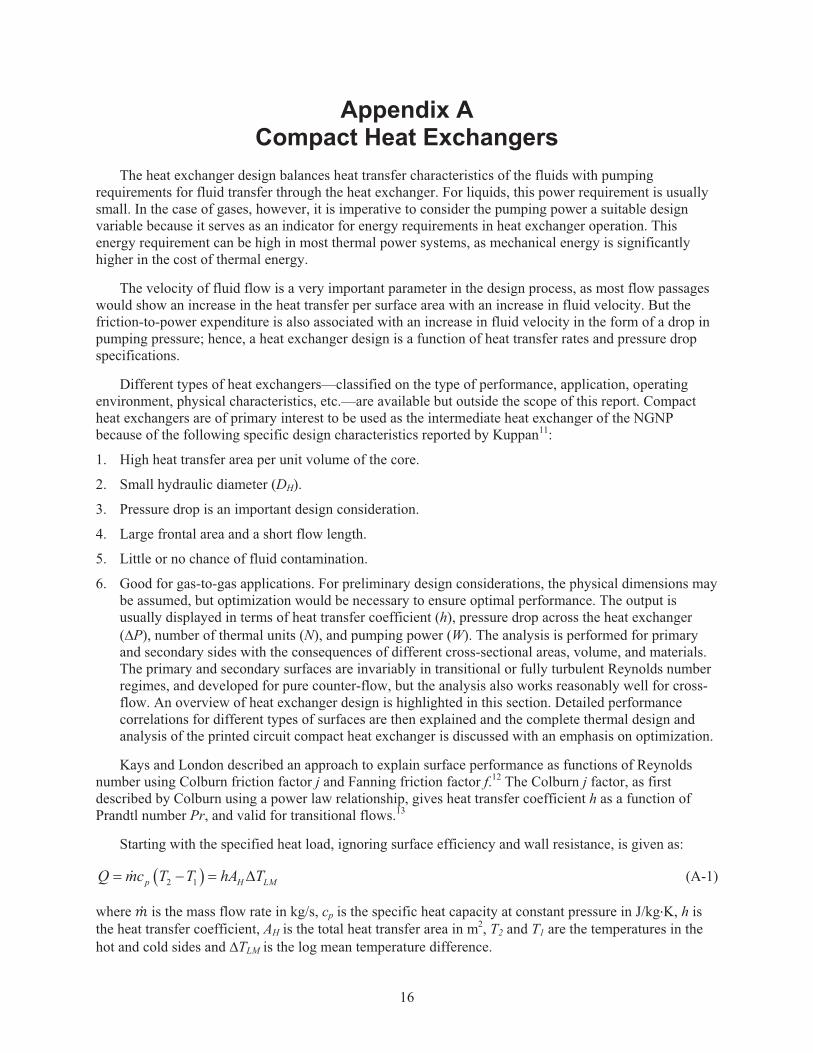
Starting with the specified heat load, ignoring surface efficiency and wall resistance, is given as:
2 1p H LMQ mc T T hA T� � � �� (A-1)
where �� is the mass flow rate in kg/s, cp is the specific heat capacity at constant pressure in J/kg�K, h is the heat transfer coefficient, AH is the total heat transfer area in m2, T2 and T1 are the temperatures in the hot and cold sides and �TLM is the log mean temperature difference.

17
The Colburn factor is expressed in terms of the heat transfer coefficient as,
2/31/3
Nuj StPrRePr
� � (A-2)
where Re is the Reynolds number, Pr is the Prandtl number, St is the Stanton number, and Nu, the Nusselt number, is given by
HhDNuk
� (A-3)
where the hydraulic diameter 4 CHAN
HH
A LDA
� and k is the thermal conductivity. Also, the friction factor
f is an important design parameter and depends on the surface characteristics and Reynolds number of the flow. The following equations were used to calculate the heat exchanger performance. One significant assumption is that the printed circuit heat exchanger has straight channels of semicircular cross section.
The cross sectional area ACHAN and perimeter P of a semicircular channel is given by
2
8
2
CHANDA
DP D
�
� �
(A-4)
where D is the diameter of the channel.
The free flow area AF and heat transfer area AH of the primary or secondary side can be evaluated from
F CHAN C
H CHAN
A N AA N L P
� �� � �
(A-5)
where NCHAN is the number of channels in the primary or secondary side and L is the length of the channel.
The heat transfer correlations for flow in semicircular ducts have been obtained from Hesselgreaves.3 The hydraulic diameter is used for noncircular ducts. The Gnielinski correlation has been employed for flows in the transitional to turbulent flow regime (2300<Re<5X10⁶) for smooth, straight semicircular ducts.14
6
23
10002 , 2300 5 10 0.5 2000
1 12.7 12
f Re PrNu Re Pr
fPr
� � �� �� �� � � � � �
� �� �� �
� �
(A-6)
where Nu is the Nusselt number, Pr the Prandtl number, Re the Reynolds number, and f is the Fanning friction factor defined by Bhatti and Shah3 as

18
1 8
7
for 2000 4000 0.0064, 2.3 10 , 2 / 3for 4000 10 0.00128, 0.1148, 3.2154
m Re A B mf A BRe
Re A B m
�� � � � � � � � �
� � �� � � � ��
(A-7)
The Gnielinski correlation has been superseded by other correlations, but has been used in this report because of the use of the correlation in RELAP5. The Darcy channel friction factor (fD) is a very vital parameter that is also used towards calculating the frictional pressure drop, which is calculated by
24 12fric D
H
Lp f VD
�� � (A-8)
where L is the flow length of the channel, � is the density, and V is the local fluid velocity. The Fanning friction factor calculated previously is different from the Darcy friction factor. The Darcy friction factor for turbulent flow in smooth round channels is estimated from the Colebrook equation as
3 71 1.5635ln 4 10 107D
Re Ref
� �� � � �� �� �
(A-9)
In this study, the channels were in the transitional flow regime, so there would be a slight correction because of uncertainty to the correlations explained above.
NOTE: The Prandtl number and other thermophysical properties such as density, specific heat capacity, and viscosity at a given temperature and pressure can be obtained from the National Institute of Standards and Technology.14

19
Appendix B
HeatricTM Printed Circuit Heat Exchangerb
b. This section has been condensed from the technical papers published by Heatric Division of Meggitt (UK) Limited. All
images are copyrighted by Heatric and have been released for informational purposes. For the complete peer-reviewed literature pertaining to Heatric PCHEs, please refer to http://www.heatric.com/technical_papers.html.

20
Appendix B HeatricTM Printed Circuit Heat Exchanger
Printed circuit heat exchangers (PCHEs) were primarily developed for refrigeration applications. They are constructed by diffusion bonding a stack of plates that have been photochemically etched. The name arises from comparisons to printed circuit board construction technology. Hesselgreaves details the construction process for the HeatricTM PCHE, the only organization currently involved in the manufacture of this type of heat exchangers.3 Using a thermal soaking period to enable grain growth, it was possible to create an interface-free bond between the plates, thus giving the heat exchanger high strength and very high operating pressure capabilities. The core of a typical HeatricTM diffusion-bonded PCHE is shown in Figure B-1. The photomicrograph of the cross section shown in Figure B-2 shows that the fluid passages are semicircular, typically1.0 to 2.0 mm wide, resulting in low hydraulic diameters of 1.5 to 3.0 mm.
Figure B-1. Core of PCHE with diffusion bonded plates (Courtesy: HeatricTM).
Figure B-2. Photomicrograph of the semicircular passages (Courtesy: HeatricTM).
HeatricTM has claimed to produce units of high surface areas, >2,500 m2, with any desired flow configuration. An example of a finished PCHE for high pressure and high temperature gas-to-gas applications is shown in Figure B-3. The presence of low hydraulic diameters is evident in the profile of the heat exchanger, which can aid high pressure duty cycles. Some of the salient features of the PCHE from HeatricTM are given below:
1. PCHEs can be four to six times smaller than conventional shell-tube heat exchangers of the same duty
2. Pressure capabilities of 600 bar and temperature range from cryogenic to 900°C, making it a likely candidate for VTHR
3. High thermal effectiveness of 98% possible with a single unit
4. Multiple process streams can be incorporated in a single unit
5. The construction process uses a wide range of materials, making them suitable for corrosive and high purity streams
6. Design life of up to 60 years (life of the reactor).

21
Figure B-3. Typical PCHE configuration (Courtesy: HeatricTM).
The limitations are the same as those of plate-fin heat exchangers, with cleaning virtually impossible in the tiny fluid passages, and design-code issues, with no nuclear approved material selection available.
Since requirements for the very high temperature reactor demand high temperatures for power generation and/or hydrogen production, the features of HeatricTM PCHEs are very appealing. Current manufacture materials include Alloy 617, Alloy 230, Alloy X and XR, Alloy 800 variants, and Alloy 602CA. Figure B-4 shows the maximum design stress for a given temperature relationship for the materials, with Alloys 617, 230, and 602CA suitable for high temperature applications; but only Alloys 617 and 230 are suitable for high pressure and temperature applications.
Figure B-4. Material properties for PCHE (ASME VIII I 2006).

22

23
Appendix C
Mapping of Semicircular Channels in RELAP5-3Dc
c. This mapping technique was implemented by Mr. Cliff B. Davis and has been used in this work with his permission.

24
Appendix C Mapping of Semicircular Channels in RELAP5-3D
The following equations were used to transform semicircular channels into rectangular channels for developing the input deck of RELAP5-3D. Transforming the channels from semicircular channels to rectangular will result in a change in the amount of metal present for heat transfer. Figure C-1 is an illustration of the parameters used in the mapping technique. For analysis, counter flow arrangement is assumed.
Figure C-1. Mapping a semicircular domain to a rectangular domain.
Let W, H, and L be the width, height and length of the heat exchanger respectively. The number of channels along width and height, given by NW and NH respectively, are defined as
; 1W HW HN Np t
� � � (C-1)
where p is the pitch, t is the plate thickness, and the total number of channels can be defined as CHAN W HN N N� � .
The cross sectional channel area of the semicircular channels,
2
8CHAN CHANdA N � �
� � �� � .
Volume of space taken by the channels, CHAN CHANV A L� � .
Volume of alloy in the heat exchanger, ALLOY CHANHXV W L H V� � � � .

25
Assuming the plate as a thick walled cylinder with an inner radius 2d
and outer radius as the thickness
of the plate (t) the area of metal available for heat transfer per channel is given by
2 2
8mALLOY
ALLOY AnnulusCHAN HX
d dVAN L
�� �
� (C-2)
where dm is an arbitrary diameter as illustrated in the semicircular channels in Figure C-1.Similarly, the arbitrary thickness, tm as illustrated in the Figure C-1, is defined as
12m mt d d� �
. (C-3)
The rectangular mapping is illustrated in Figure C-1, with the addition of a new parameter d1, which can be found out by the area of the rectangular channel, the same as the area of the semicircular channel as
2
1 18 8RECT ANNULUSd dA A d d d
� � � � � � (C-4)
Likewise dm and tm for the rectangular mapping can be found by
11 1
12
ALLOYALLOY m m m m
A d dA p d d d d t d d
p� �
� � � � � � � � �. (C-5)
The physical conduction thickness of the metal between channels varies along the circumference of
the semicircular channel, i.e. 2dt x t� �� � �� �
� � so the effective thickness can be calculated as the mean of
the limits given by
/ 22 4eff
t t d dt t t� �� � � �
(C-6)
This effective conduction thickness will be used to modify the volumetric heat capacity of Inconel 617 alloy to preserve the thermal capacitance of the heat structure component in RELAP5-3D.