modeling, analysis a nd fabrication of a · pdf filein the slow speed engines, the crankshafts...
TRANSCRIPT
http://www.iaeme.com/IJCIET/index.asp 368 [email protected]
International Journal of Civil Engineering and Technology (IJCIET) Volume 8, Issue 5, May 2017, pp. 368–377, Article ID: IJCIET_08_05_043 Available online at http://www.iaeme.com/IJCIET/issues.asp?JType=IJCIET&VType=8&IType=5 ISSN Print: 0976-6308 and ISSN Online: 0976-6316 © IAEME Publication Scopus Indexed
MODELING, ANALYSIS AND FABRICATION OF A PISTON ENGINE CRANK SHAFT
M. Ganesh Department of Aeronautical Engineering,
MLR Institute of Technology, Hyderabad, India
A. Sai Kumar Department of Aeronautical Engineering,
MLR Institute of Technology, Hyderabad, India
ABSTRACT A crankshaft is an important component of the automobile which converts the
reciprocating displacement of the engine to rotary motion. The crankshaft undergoes several load cycles during its life. Hence the crankshaft material has to feature high strength and toughness, high resistance to wear and fatigue stresses, resistance to impact loads and hardness such properties are possessed by properly machined carbon and alloyed steels and high duty cast iron. In medium speed engines, the crankshaft is usually forged. In the slow speed engines, the crankshafts are semi built with the webs and crankpins forged or cast in one piece and then shrunk onto the journals. Here we will model and fabricate a crankshaft by analyzing its each and every component and designing it in Pro-E and fabricate using Lathe Machine. We model and fabricate here the crank- shaft analyzing it by FEM. Possible alternatives to the thrust-crank-mechanism have not been able to assert themselves. Whereby, all together, rather more problems arose with the gear-rack of the atmospheric gas engine and also with the ingenious solution of the rotary engine than fewer. There have even been engines without connecting rods and crankshaft which transmitted their force hydraulically.
Key words: Crankshaft, Engines, Fabrication, FEM, Lathe, etc. Cite this Article: M. Ganesh and A. Sai Kumar, Modeling, Analysis and Fabrication of a Piston Engine Crank Shaft. International Journal of Civil Engineering and Technology, 8(5), 2017, pp. 368–377. http://www.iaeme.com/IJCIET/issues.asp?JType=IJCIET&VType=8&IType=5
1. INTRODUCTION The Crankshaft which is often referred to as a ‘Crank’ is a part of an engine that converts the reciprocating piston motion into rotary motion. To convert the reciprocating motion into rotary motion, the crankshaft has crankpins, bearing surfaces whose axis is offset from that of crank, to which the big ends of connecting rods from each cylinder attach. The crankshaft is

Modeling, Analysis and Fabrication of a Piston Engine Crank Shaft
http://www.iaeme.com/IJCIET/index.asp 369 [email protected]
connected to the flywheel to reduce the torsional vibration often caused along the length of the crankshaft by the cylinders. The crankshaft has a linear axis about which it rotates, with several bearing journals (the main bearings) held in the engine block. As a crankshaft undergoes a great deal of load from each cylinder in the multi cylinder engine, it must be supported by several such bearings, better will be performance.
Figure 1 Main parts of a crankshaft
For Some Engines, it is necessary to provide counterweights for the reciprocating mass of each piston and connecting rod to improve engine balance. While counterweights add a considerable amount of weight to the crankshaft, it provides a smoother running and allows higher rpm levels to be reached. Some expensive high performance crankshafts also use heavy metal counterweights to make the crankshaft more compact. Tungsten alloy and uranium is used for making counterweights, but the cheaper option is to use lead, because its density is less when compared to other materials.
A crankshaft contains two or more centrally-located coaxial cylindrical ("main") journals and one or more offset cylindrical crankpin ("rod") journals. The two-plane V8 crankshaft has five main journals and four rod journals, each spaced 90° from its neighbors. The crankshaft main journals rotate in a set of supporting bearings ("main bearings"), causing the offset rod journals to rotate in a circular path around the main journal centers. The diameter of that path is the engine "stroke": the distance the piston moves up and down in its cylinder. The big ends of the connecting rods ("conrods") contain bearings ("rod bearings") which ride on the offset rod journals.
1.1. Design Issues In the world of component design, there are competing criteria, which require the engineers to achieve a perceived optimal compromise to satisfy the requirements of their particular efforts. Discussions with various recognized experts in the crankshaft field make it abundantly clear that there is no ‘right’ answer, and opinions about the priorities of design criteria vary considerably. In contemporary racing crankshaft design, the requirements for bending and torsional stiffness compete with the need for low mass moment of inertia (MMOI). High stiffness is a benefit because it increases the tensional resonant frequency of the crankshaft, and because it reduces bending deflection of the bearing journals. At this point, it is important to digress and emphasize the often-misunderstood difference between ‘Stiffness’ and ‘Strength’.
The degree to which a given part resists deflection in response to a given loading is called stiffness. It is important to understand that the ultimate strength of a material has
M. Ganesh and A. Sai Kumar
http://www.iaeme.com/IJCIET/index.asp 370 [email protected]
nothing whatever to do with stiffness. Stiffness is the result of two properties i.e., the Young's Modulus of the material and the Cross-Sectionalproperties of the part to which the load is applied.
Since the current crankshaft materials are alloy steels, the Young's Modulus is fairly constant. That means that altering the section properties of the highly-stressed portions of the crankshaft is the only way to increase stiffness.
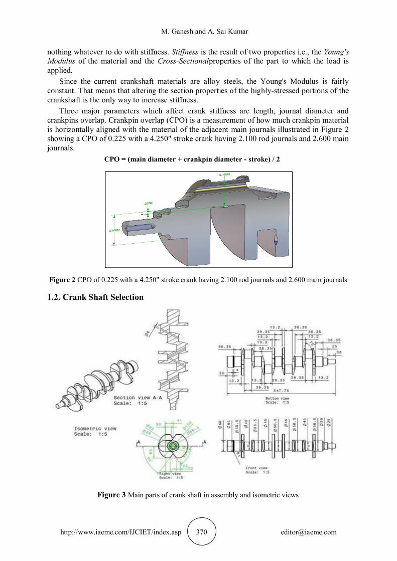
Three major parameters which affect crank stiffness are length, journal diameter and crankpins overlap. Crankpin overlap (CPO) is a measurement of how much crankpin material is horizontally aligned with the material of the adjacent main journals illustrated in Figure 2 showing a CPO of 0.225 with a 4.250" stroke crank having 2.100 rod journals and 2.600 main journals.
CPO = (main diameter + crankpin diameter - stroke) / 2
Figure 2 CPO of 0.225 with a 4.250" stroke crank having 2.100 rod journals and 2.600 main journals
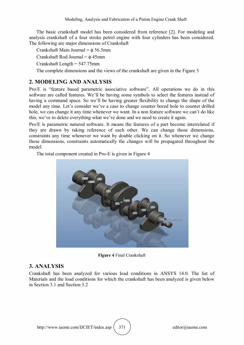
1.2. Crank Shaft Selection
Figure 3 Main parts of crank shaft in assembly and isometric views
Modeling, Analysis and Fabrication of a Piston Engine Crank Shaft
http://www.iaeme.com/IJCIET/index.asp 371 [email protected]
The basic crankshaft model has been considered from reference [2]. For modeling and analysis crankshaft of a four stroke petrol engine with four cylinders has been considered. The following are major dimensions of Crankshaft
Crankshaft Main Journal = ϕ 56.5mm Crankshaft Rod Journal = ϕ 45mm Crankshaft Length = 547.75mm The complete dimensions and the views of the crankshaft are given in the Figure 3
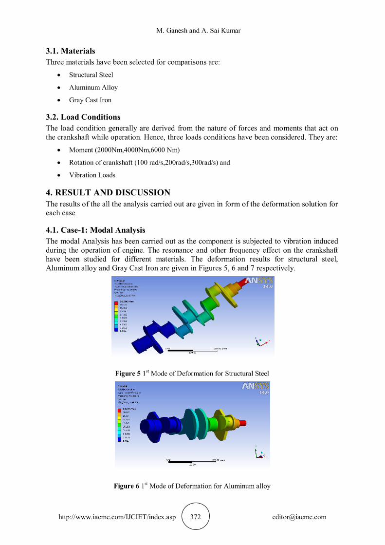
2. MODELING AND ANALYSIS Pro/E is “feature based parametric associative software”. All operations we do in this software are called features. We’ll be having some symbols to select the features instead of having a command space. So we’ll be having greater flexibility to change the shape of the model any time. Let’s consider we’ve a case to change counter bored hole to counter drilled hole, we can change it any time whenever we want. In a non feature software we can’t do like this, we’ve to delete everything what we’ve done and we need to create it again. Pro/E is parametric natured software. It means the features of a part become interrelated if they are drawn by taking reference of each other. We can change those dimensions, constraints any time whenever we want by double clicking on it. So whenever we change those dimensions, constraints automatically the changes will be propagated throughout the model.
The total component created in Pro-E is given in Figure 4
Figure 4 Final Crankshaft
3. ANALYSIS Crankshaft has been analyzed for various load conditions in ANSYS 14.0. The list of Materials and the load conditions for which the crankshaft has been analyzed is given below in Section 3.1 and Section 3.2
M. Ganesh and A. Sai Kumar
http://www.iaeme.com/IJCIET/index.asp 372 [email protected]
3.1. Materials Three materials have been selected for comparisons are:
Structural Steel
Aluminum Alloy
Gray Cast Iron
3.2. Load Conditions The load condition generally are derived from the nature of forces and moments that act on the crankshaft while operation. Hence, three loads conditions have been considered. They are:
Moment (2000Nm,4000Nm,6000 Nm)
Rotation of crankshaft (100 rad/s,200rad/s,300rad/s) and
Vibration Loads
4. RESULT AND DISCUSSION The results of the all the analysis carried out are given in form of the deformation solution for each case
4.1. Case-1: Modal Analysis The modal Analysis has been carried out as the component is subjected to vibration induced during the operation of engine. The resonance and other frequency effect on the crankshaft have been studied for different materials. The deformation results for structural steel, Aluminum alloy and Gray Cast Iron are given in Figures 5, 6 and 7 respectively.
Figure 5 1st Mode of Deformation for Structural Steel
Figure 6 1st Mode of Deformation for Aluminum alloy
Modeling, Analysis and Fabrication of a Piston Engine Crank Shaft
http://www.iaeme.com/IJCIET/index.asp 373 [email protected]
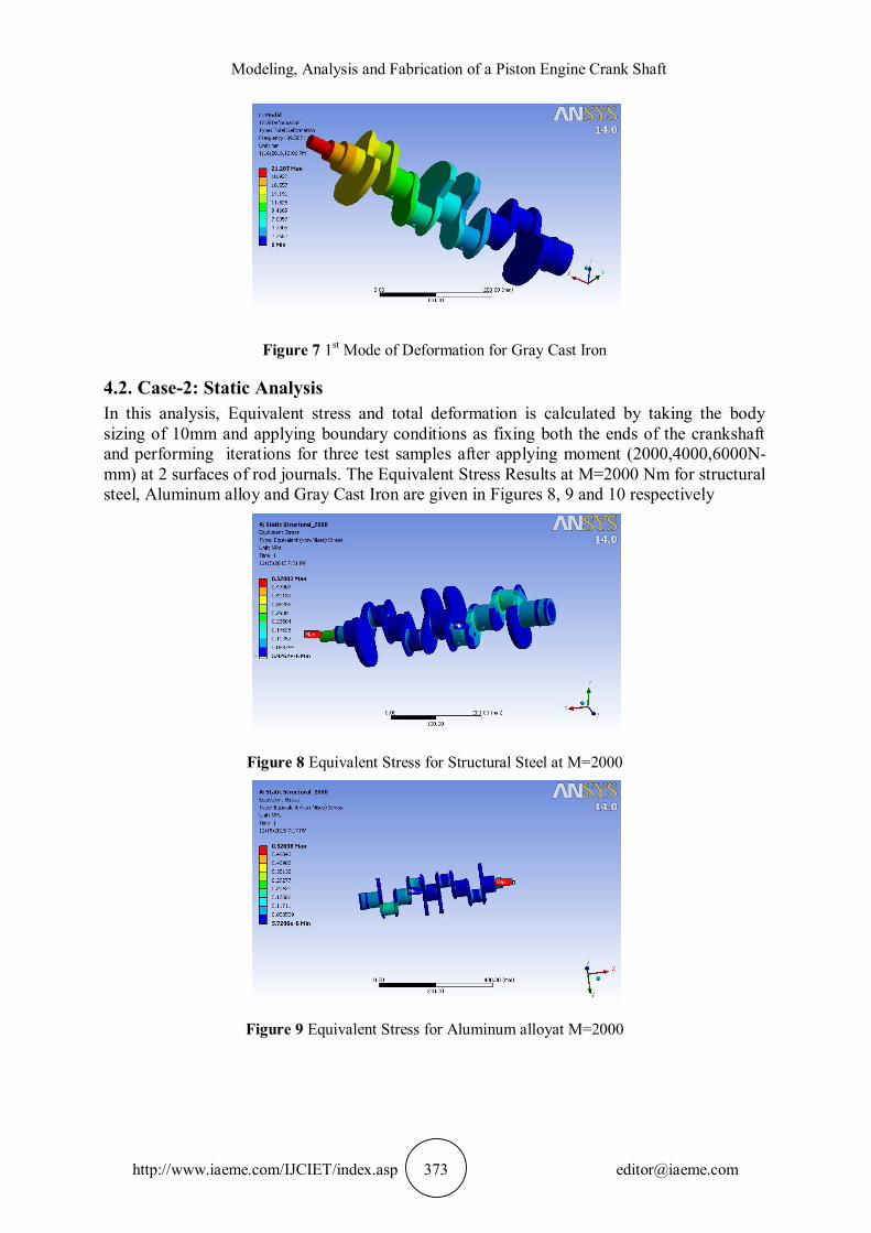
Figure 7 1st Mode of Deformation for Gray Cast Iron
4.2. Case-2: Static Analysis In this analysis, Equivalent stress and total deformation is calculated by taking the body sizing of 10mm and applying boundary conditions as fixing both the ends of the crankshaft and performing iterations for three test samples after applying moment (2000,4000,6000N-mm) at 2 surfaces of rod journals. The Equivalent Stress Results at M=2000 Nm for structural steel, Aluminum alloy and Gray Cast Iron are given in Figures 8, 9 and 10 respectively
Figure 8 Equivalent Stress for Structural Steel at M=2000
Figure 9 Equivalent Stress for Aluminum alloyat M=2000
M. Ganesh and A. Sai Kumar
http://www.iaeme.com/IJCIET/index.asp 374 [email protected]
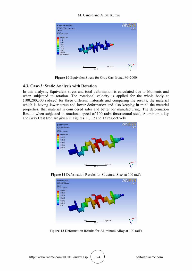
Figure 10 EquivalentStress for Gray Cast Ironat M=2000
4.3. Case-3: Static Analysis with Rotation In this analysis, Equivalent stress and total deformation is calculated due to Moments and when subjected to rotation. The rotational velocity is applied for the whole body at (100,200,300 rad/sec) for three different materials and comparing the results, the material which is having lower stress and lower deformation and also keeping in mind the material properties, that material is considered safer and better for manufacturing. The deformation Results when subjected to rotational speed of 100 rad/s forstructural steel, Aluminum alloy and Gray Cast Iron are given in Figures 11, 12 and 13 respectively
Figure 11 Deformation Results for Structural Steel at 100 rad/s
Figure 12 Deformation Results for Aluminum Alloy at 100 rad/s

Modeling, Analysis and Fabrication of a Piston Engine Crank Shaft
http://www.iaeme.com/IJCIET/index.asp 375 [email protected]
Figure 13 Deformation Results for Gray Cast Ironat 100 rad/s
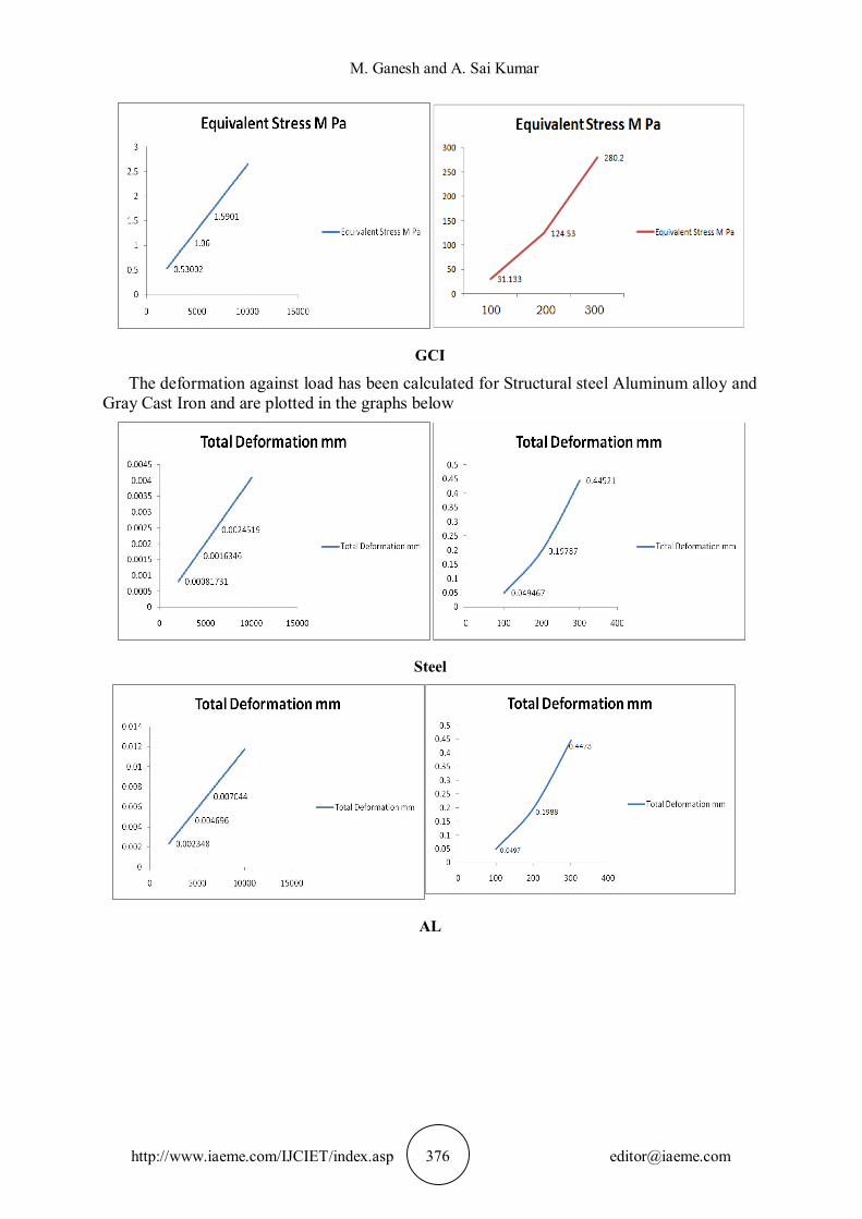
4.4. Discussion The graphs have been plotted for each material for load v/s deformation and load v/s stress developed in the component
The variation equivalent stress against load (with and without rotation) has been calculated for Structural steel Aluminum alloy and Gray Cast Iron and are plotted in the graphs below
For steel with rotation For steel without rotation
For AL with rotation For AL without rotation
M. Ganesh and A. Sai Kumar
http://www.iaeme.com/IJCIET/index.asp 376 [email protected]
GCI
The deformation against load has been calculated for Structural steel Aluminum alloy and Gray Cast Iron and are plotted in the graphs below
Steel
AL

Modeling, Analysis and Fabrication of a Piston Engine Crank Shaft
http://www.iaeme.com/IJCIET/index.asp 377 [email protected]
GCI
5. CONCLUSION Based on the results obtained, the following can be concluded
According to the Results, the Max. Stress of Structural steel, Aluminum alloy and Gray cast iron are very close, but as per the material properties and the deformation occurs for these materials, structural steel will be good for the manufacturing.
Based on the results, Structural Steel is considered best for manufacturing the crankshaft as it is having less frequency, less equivalent stress, less deformation, and it has high tensile strength, high melting point, high density, higher strengths at low weights, less expensive, when compared to Aluminum alloy and Gray cast iron.
6. FUTURE SCOPE The work can be extended to fabrication and testing of the model in place of another crankshaft of similar dimensions for the validation.
REFERENCES [1] Xiaorong Zhou., Ganwei Cai., 2009, “Analysis on Dynamic Characteristics of Internal
Combustion Engine Crankshaft System,” International Conference on Measuring Technology and Mechatronics Automation.
[2] Jensen, E. J., 1970, “Crankshaft Strength through Laboratory Testing,” SAE Technical Paper No. 700526, Society of Automotive Engineers.
[3] Amitabha Ghosh and Kumar mallik, “Machining Process”, affiliated eat-west press Pvt.Ltd. New Delhi.
[4] M. Zoroufi and A.Fatemi, “Review on Durability evaluation of Crankshafts including comparisons of competing manufacturing processes and cost analysis”, the university of Toledo, Toledo, Ohio.
[5] Silva, F. S., 2003, “An Investigation into the Mechanism of a Crankshaft Failure,” Key Engineering Materials, Vols. 245-246, pp. 351-358.
[6] Park, H., Ko, Y. S., and Jung, S. C., 2001, “Fatigue Life Analysis of Crankshaft at Various Surface Treatments,” SAE Technical Paper No. 2001-01-3374, Society of Automotive Engineers.