modeling and simulation of electromechanical … and simulation of electromechanical systems...
TRANSCRIPT

1© 2015 The MathWorks, Inc.
Modeling and Simulation of Electromechanical
Systems
Dhirendra Singh
[email protected] Vivek Raju
Application Engineer Application Engineer
2
Challenges
Working with Multi-Domain systems (Mechanical, Electrical)
Modeling Kinematics & Mechanisms of Mechanical design
Determine the sizing of the electrical components like motors and optimize the parameters
Develop appropriate control logic (Field oriented control and event based control logic)
Perform real-time simulation for rapid control prototyping and hardware-in-the-loop simulation
3
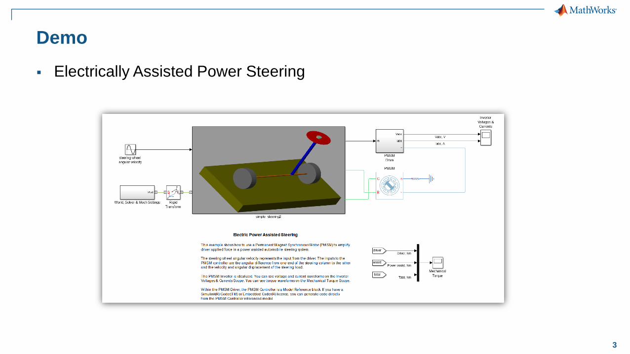
Demo
Electrically Assisted Power Steering
4
Challenge 1:
Working with Multi-Domain systems (Mechanical,
Electrical)
To address this challenge
We need to have a platform which allows working with Electrical, Mechanical
and Control system in a single environment
5
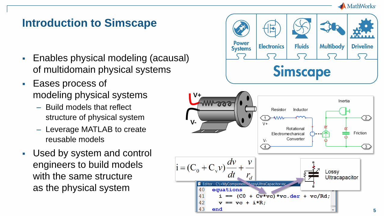
Introduction to Simscape
Enables physical modeling (acausal)
of multidomain physical systems
Eases process of
modeling physical systems
– Build models that reflect
structure of physical system
– Leverage MATLAB to create
reusable models
Used by system and control
engineers to build models
with the same structure
as the physical system
V+
V-
6
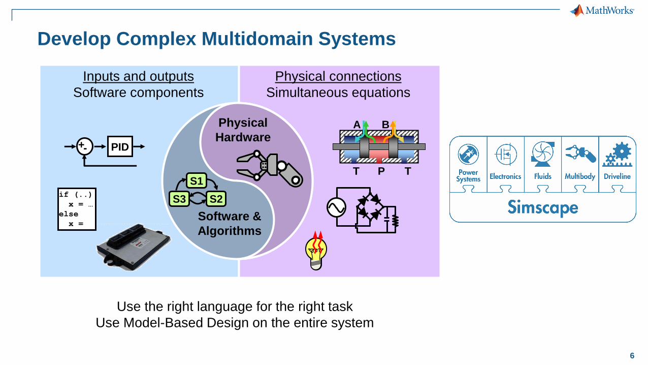
Develop Complex Multidomain Systems
Physical
Hardware
S1
S2S3
Software &
Algorithms
A B
P TT
PID+-
if (..)
x = …
else
x =
Inputs and outputs
Software components
Physical connections
Simultaneous equations
Use the right language for the right task
Use Model-Based Design on the entire system
7
Challenge 2:
Modeling Kinematics & Mechanisms of Mechanical
design
To address this challenge
We need to have platform to model kinematics and mechanisms of mechanical
systems and simulate the dynamics.
We also require to import existing enterprise CAD models.

8
Modeling Kinematics & Mechanisms of Mechanical design
Enables multibody simulation
of 3D mechanical systems
Construct model using
bodies, joints, and forces
– Model matches structure of system
– No need to derive and program equations
Primary uses
– System-level analysis of
mechanical and multidomain systems
– Control development in Simulink
9
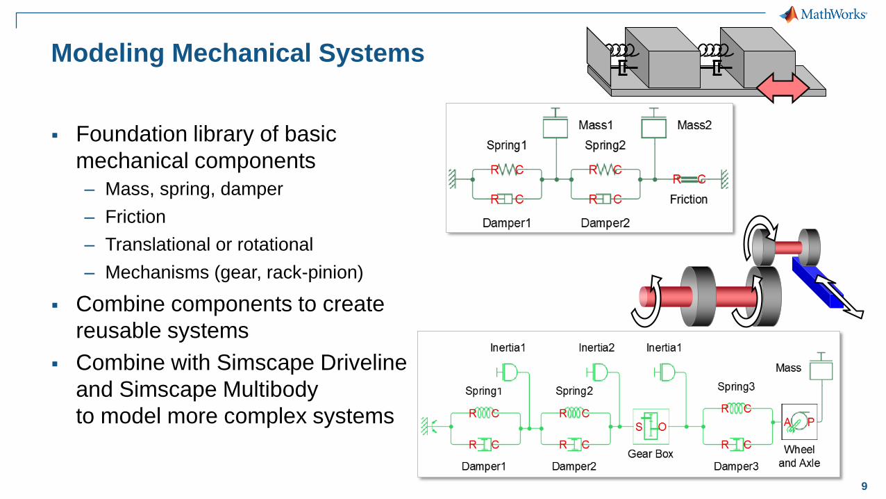
Modeling Mechanical Systems
Foundation library of basic
mechanical components
– Mass, spring, damper
– Friction
– Translational or rotational
– Mechanisms (gear, rack-pinion)
Combine components to create
reusable systems
Combine with Simscape Driveline
and Simscape Multibody
to model more complex systems

10
Working with
Simscape Multibody
Build components
– Predefined solids
– Extrusions defined in MATLAB
Parameterize components
– MATLAB variables
– Custom dialog boxes
Connect with joints
– Sense and actuate
– Guide assembly

11
CAD to MATLAB
to Simscape Multibody
1. Export from CAD to MATLAB code
– SolidWorks:
CAD2MATLAB_SolidWorks.swp
– Other CAD System: Adapt code
to your CAD system’s API
2. Run MATLAB code to create
data structure in MATLAB
3. Run data2smixml.m to generate
Simscape Multibody XML file
4. Import Simscape Multibody XML file
to create Simscape Multibody model
parameterized with STL files
for animation.
CAD
robot.m
smiModel
robot.xml
robot.slx
>> robot.m
>> smimport(‘robot.xml’)
2
4
part.STL
CAD2MATLAB_SolidWorks.swp
3
1
>> data2smixml(smiModel,’robot.xml’)
12
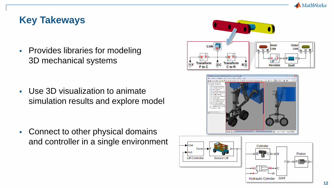
Key Takeways
Provides libraries for modeling
3D mechanical systems
Use 3D visualization to animate
simulation results and explore model
Connect to other physical domains
and controller in a single environment

13
Challenges
Working with Multi-Domain systems (Mechanical, Electrical)
Modeling Kinematics & Mechanisms of Mechanical design
Determine the sizing of the electrical components like motors and optimize the parameters
Develop appropriate control logic (Field oriented control and event based control logic)
Perform real-time simulation for rapid control prototyping and hardware-in-the-loop simulation
14
Challenge 3:
Determine the sizing of the electrical components like
motors and optimize the parameters
To address this challenge
We need to model the motor, analyze the behavior by simulating the model and
optimize the parameters of the electromechanical system.
15
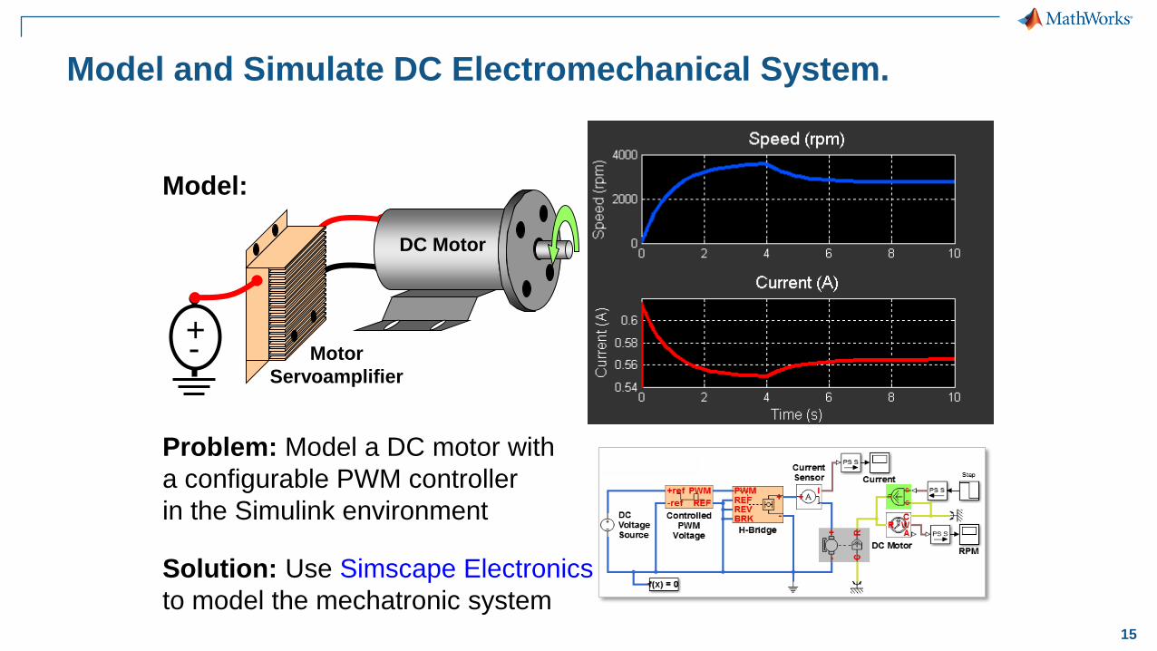
Model and Simulate DC Electromechanical System.
Problem: Model a DC motor with
a configurable PWM controller
in the Simulink environment
Solution: Use Simscape Electronics
to model the mechatronic system
Model:
DC Motor
Motor
Servoamplifier
+-

16
Modeling 3-Phase Electrical Systems
Problem: Build a modular,
intuitive model of a 3-phase
electric motor without deriving
equations.
Solution: Use Simscape Power
Systems to model the System.
Model:
a
b
c

17
Estimating Model Parameters of Motor
R L J K B
3 0.01 0.01 0.02 0.5
Problem: Simulation data does not
match measured data because the
parameters are incorrect
Solution: Use Simulink Design
Optimization to automatically tune
model parameters
Model:
+- 12V
Up
Up Down
Down
V+V-
R = Resistance
L = Inductance
J = Inertia
B = Friction
K = Back EMF Constant
R L J K B
4.03 1e-4 0.11 0.45 1.07
18
Challenge 4:
Develop appropriate control logic (Field oriented
control and event based control logic)
To address this challenge
We need to tune the proportional and integral values to an
appropriate level for a smooth steering control.

19
Optimize System-Level Performance
and Meet Design Requirements
Simulating plant and controller in one environment allows you to optimize
system-level performance
Plant
+u y
Controller
s1 s2
s3

20
Demo: Field Oriented Control of PMSM
3-Phase
Inverter
PMSM
Motor
Va Vb Vc
Space
Vector
PWM
Position & Speed
Sensing
PIInv_Park
Transform
d,q
To
alpha,beta
Clark
Transform
a,b,c
to
alpha, beta
Ia
Ib
Park
Transform
alpha, beta
to
d, q
Is_alpha
Is_beta
Vs_alpha
Vs_beta
PI
PI
Vsq_ref
Vsd_refIsd_ref
_
_
+Isq_ref
Is_d
Is_q
Desired
RPM
_
RPM
theta

21
Challenge 5:
Perform real-time simulation for rapid control prototyping and
hardware-in-the-loop simulation
To address this challenge
We need to have a real-time operating system to quickly prototype the control
system before implementing in an embedded processor and also perform an
hardware-in-the-loop simulation.

22
Simulink Real-Time Enables Real-Time
Simulation and Testing
Rapidly create real-time applications from Simulink
models and run and test them with your hardware under
test at normal operating frequencies, speeds, and timing. Metso was able to
achieve multiple goals
simultaneously. They
were able to developed a
sophisticated controller
for digital hydraulics that
is more reliable, accurate,
and efficient than
previous systems, and
they were able to
accelerate their
development.
“Simulations in Simulink
and real-time testing with
Simulink Real-time
helped us deliver an
exceptionally reliable
control system.”
Kari Leminen, Metso
23
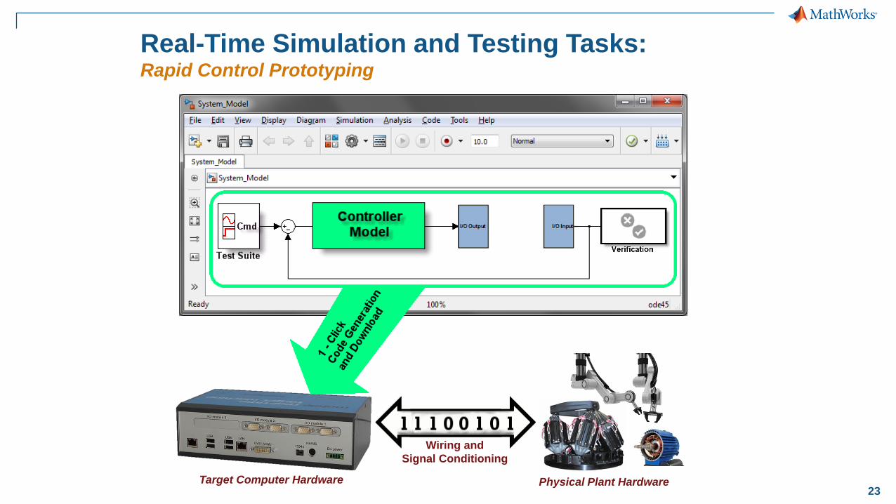
I/O Output I/O InputI/O Output I/O Input
Real-Time Simulation and Testing Tasks: Rapid Control Prototyping
Physical Plant Hardware
Wiring and
Signal Conditioning
0
0
Target Computer Hardware

24
Wiring and
Signal Conditioning
Embedded Controller HardwareTarget Computer Hardware
Real-Time Simulation and Testing Tasks: Hardware-in-the-loop (HIL) Simulation