modeling complex structures in electromagnetics using ... · modeling complex structures in...
TRANSCRIPT

Modeling complex structures in
electromagnetics using hybrid algorithm
Presented by: Kapil Sharma
110th Annual Symposium on Signal Integrity

Presentation Outline
• Introduction
• Research motivation
• Common CEM techniques
• Problem definition
• Past research work
• Novel hybrid technique
• Numerical examples and simulation results
• Observations
• Future research
• References
210th Annual Symposium on Signal Integrity

Introduction: Modeling Challenges in
Current Technologies
3
Solar Cells (Plasmonics)
Composite Layers (Inhomogeneous)
Embedded Antenna (Multiscale)
Nano Rods (Thin and Long)
Sub micron Die (Signal Integrity)Graphene
(Fine Thickness )
10th Annual Symposium on Signal Integrity

Research Motivation
• Ubiquity of complex multi-scale problems in numerical
electromagnetics
410th Annual Symposium on Signal Integrity

Research Motivation
• Simulation of structures with multi-scale features is highly
challenging
5
Fine feature captured by
conventional FDTD mesh
-0.5 -0.4 -0.3 -0.2 -0.1 0 0.1 0.2 0.3 0.4 0.50
0.05
0.1
0.15
0.2
0.25
0.3
0.35
0.4
Distance along Z in
Am
plit
ude in V
/m
Amplitude Variation of Scattered Ey
DM Appraoch
HFSS
0 0.2 0.4 0.6 0.8 1 1.2 1.4 1.6 1.8 20.4
0.6
0.8
1
1.2
1.4
1.6
Distance along Y in
Am
plit
ude in V
/m
Amplitude Comparison of Ez from New Conformal FDTD
New Conformal FDTD
GEMS
FEKO
HFSS
Spurious Ripples!
Dielectric Cuboid
Plasmonic Nano-spheres
10th Annual Symposium on Signal Integrity

Common CEM techniques
• FDTD
• Solves for a wide frequency range
• Computationally expensive when handling fine structures, resonant structures, and
dispersive media
• MoM
• Solves at a single frequency
• Singularity extraction requires special treatment
• Handles dispersive media well, but computationally expensive when handling fine
structures
• FEM
• Solves at a single frequency
• Computationally expensive for fine and resonant structures
• FIT
• Solves for a wide frequency range
• Computationally expensive when handling fine structures, resonant
structures, and dispersive media
610th Annual Symposium on Signal Integrity
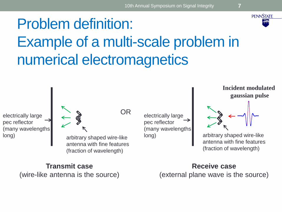
Problem definition:
Example of a multi-scale problem in
numerical electromagnetics
7
OR
arbitrary shaped wire-like
antenna with fine features
(fraction of wavelength)
electrically large
pec reflector
(many wavelengths
long)
Transmit case
(wire-like antenna is the source)
Receive case
(external plane wave is the source)
arbitrary shaped wire-like
antenna with fine features
(fraction of wavelength)
electrically large
pec reflector
(many wavelengths
long)0 0.5 1 1.5 2 2.5
-3
-2
-1
0
1
2
3
4x 10
9
t (ns)
x(t
)
analytical
iDFT
Incident modulated
gaussian pulse
10th Annual Symposium on Signal Integrity

Proposed hybrid technique
8
The novel hybrid FDTD
technique combines the MoM
and FDTD techniques directly in
the time domain
Fine features are handled by
MOM code
Special basis functions are used to
represent current on wire-like
geometries with fine features
Time domain scattered fields are
sampled at a planar interface
Sampled time domain scattered fields
are then combined with the
conventional FDTD update equations
10th Annual Symposium on Signal Integrity

Problem Definition – validation of
MoM code
X
Z
λ @ highest frequency of interest: 4 GHz
Observation Line
A straight wire is directed along x.
Length of the straight wire is 0.75 cm
Straight wire antenna of length 0.75 cm with
a delta gap voltage source
9
Wire antenna radius = 0.005*length
10th Annual Symposium on Signal Integrity

MoM code vs FEKO results
-1.5 -1 -0.5 00
5
10
15
20
Amplitude of Ex
Distance Along Z in
Am
plit
ud
e in
V/m
MOM code
FEKO
Magnitude comparison
-1.5 -1 -0.5 0120
140
160
180
200
220
240
Phase of Ex
Distance Along Z in
Ph
ase
in
De
gre
e
MOM code
FEKO
Phase comparison
1010th Annual Symposium on Signal Integrity

Transmit Case: Example 1
11
X
Z
FDTD domain mesh size: λ/20
λ @ highest frequency of interest: 8 GHz
λ0 @ center frequency of interest: 4 GHz
Observation Line
A straight wire antenna is directed along x at a distance of 7.5 cm
from a pec plate
Length of the straight wire antenna is 0.1875 cm from the wire antenna
Straight wire antenna of length 0.1875 cm
with a delta gap voltage source7.5 cm
pec plate(26.25 cm x 26.25 cm)
Planar Interface (26.25 cm x 26.25 cm)
0.1875 cm
Variable Value
λ 3.75 cm
λ0 7.5 cm
λ/20 0.1875 cm
FDTD domain
MoM domain
Wire antenna radius = 0.005*length
MoM domain solution is obtained in the
time-domain
10th Annual Symposium on Signal Integrity
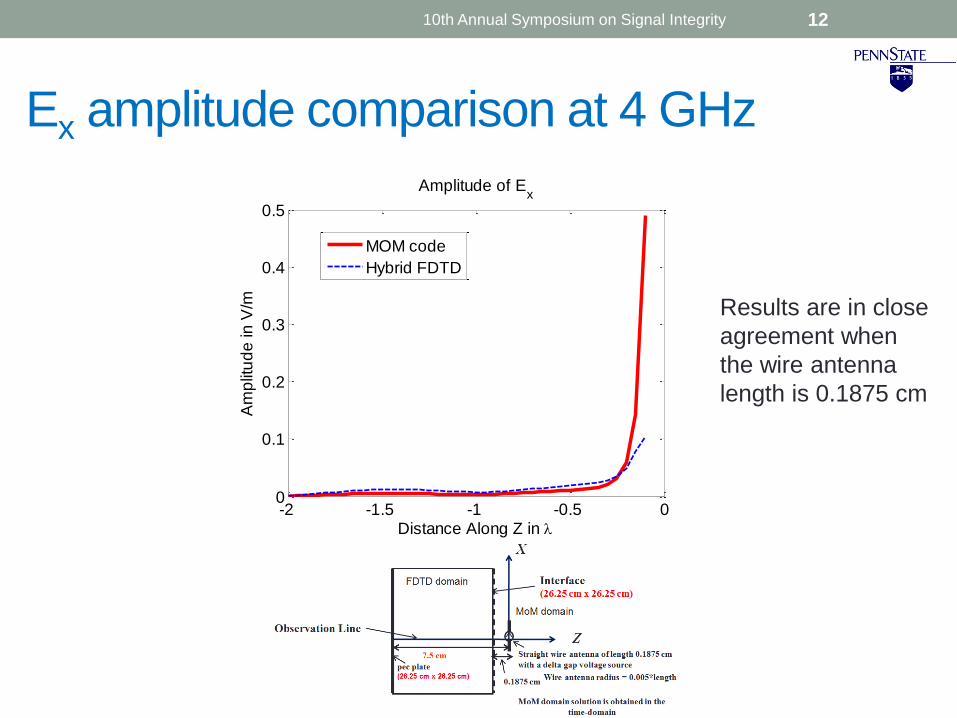
Ex amplitude comparison at 4 GHz
12
-2 -1.5 -1 -0.5 00
0.1
0.2
0.3
0.4
0.5
Amplitude of Ex
Distance Along Z in
Am
plit
ud
e in
V/m
MOM code
Hybrid FDTD
Results are in close
agreement when
the wire antenna
length is 0.1875 cm
10th Annual Symposium on Signal Integrity

Ex phase comparison at 4 GHz
13
-2 -1.5 -1 -0.5 0-50
0
50
100
150
200
250
Phase of Ex
Distance Along Z in
Ph
ase
in
De
gre
e
MOM code
Hybrid FDTD
Results are in close
agreement when
the wire antenna
length is 0.1875 cm
10th Annual Symposium on Signal Integrity

Transmit Case: Example 2
14
A straight wire antenna is directed along x at a distance of 7.5 cm
from a pec plate
Length of the straight wire antenna is 0.75 cm from the wire antenna
X
Z
FDTD domain mesh size: λ/20
λ @ highest frequency of interest: 8 GHz
λ0 @ center frequency of interest: 4 GHz
Observation Line
Straight wire antenna of length 0.75 cm
with a delta gap voltage source7.5 cm
pec plate(26.25 cm x 26.25 cm)
Planar Interface (26.25 cm x 26.25 cm)
0.1875 cm
Variable Value
λ 3.75 cm
λ0 7.5 cm
λ/20 0.1875 cmFDTD domain
MoM domain
Wire antenna radius = 0.005*length
MoM domain solution is obtained in the
time-domain
10th Annual Symposium on Signal Integrity

Ex amplitude comparison at 4 GHz
15
-2 -1.5 -1 -0.5 00
5
10
15
20
Amplitude of Ex
Distance Along Z in
Am
plit
ud
e in
V/m
MOM code
Hybrid FDTD
Results are in close
agreement when the
wire antenna length is
increased to 0.75 cm
10th Annual Symposium on Signal Integrity
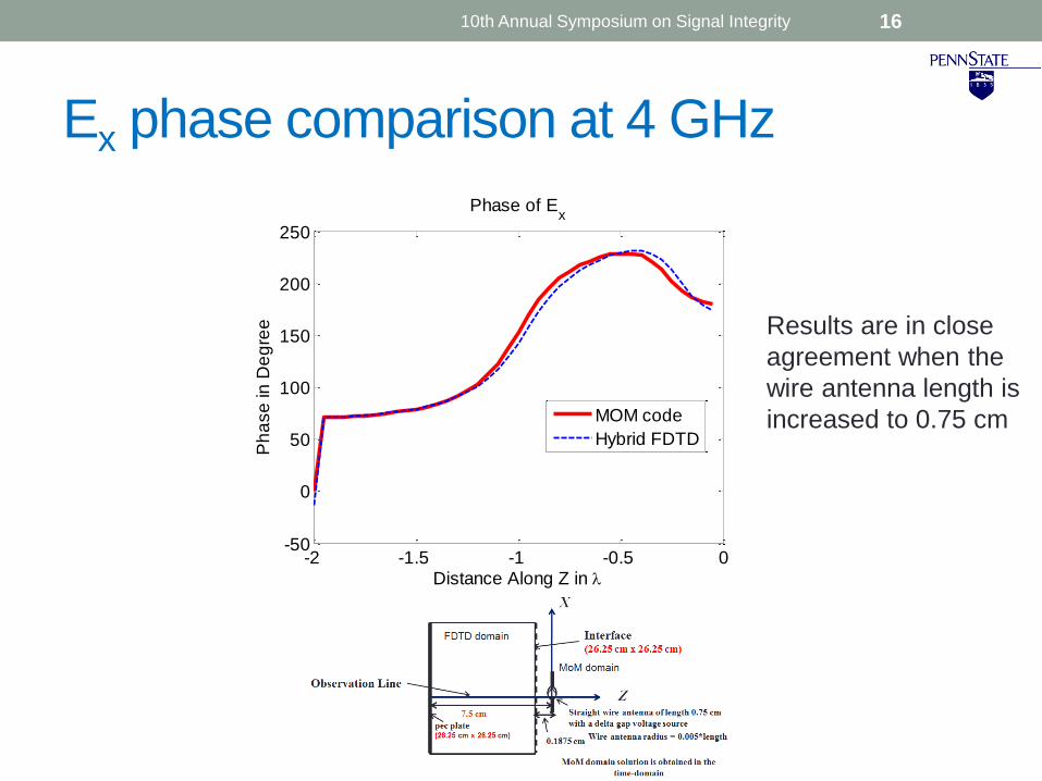
Ex phase comparison at 4 GHz
16
-2 -1.5 -1 -0.5 0-50
0
50
100
150
200
250
Phase of Ex
Distance Along Z in
Ph
ase
in
De
gre
e
MOM code
Hybrid FDTD
Results are in close
agreement when the
wire antenna length is
increased to 0.75 cm
10th Annual Symposium on Signal Integrity

Receive Case: Example 1
17
X
Z
Mesh size: λ/20
λ @ highest frequency of interest: 8 GHz
λ0 @ center frequency of interest: 4 GHz
Observation Line
0.1875 cm
Planar Interface(26.25 cm x 26.25 cm)
A straight wire antenna is directed along x at a distance of 7.5 cm from a pec plate
Length of the straight wire antenna is 0.1875 cm
Planar Interface is at a distance 0.1875 cm from the wire antenna
Straight wire antenna of length 0.1875 cm7.5 cm
pec plate
(26.25 cm x 26.25 cm)
Variable Value
λ 3.75 cm
λ0 7.5 cm
λ/20 0.1875 cm
FDTD domain
MoM domain
0 0.5 1 1.5 2 2.5-3
-2
-1
0
1
2
3
4x 10
9
t (ns)
x(t
)
analytical
iDFT
k
Wire antenna radius = 0.005*length
Incident modulated
gaussian pulse
MoM domain solution is obtained in the
time-domain
10th Annual Symposium on Signal Integrity

Ex amplitude comparison at 4 GHz
18
-2 -1.5 -1 -0.5 00
1
x 10-4 Amplitude of E
x
Distance Along Z in
Am
plit
ud
e in
V/m
MOM code
Hybrid FDTD
Results are in close
agreement when the
wire antenna length
is 0.1875 cm
10th Annual Symposium on Signal Integrity

Ex phase comparison at 4 GHz
19
-2 -1.5 -1 -0.5 0-100
-50
0
50
100
150
200
Phase of Ex
Distance Along Z in
Ph
ase
in
De
gre
e
MOM code
Hybrid FDTD
Results are in close
agreement when the
wire antenna length
is 0.1875 cm
10th Annual Symposium on Signal Integrity

Receive Case: Example 2
20
X
Z
Mesh size: λ/20
λ @ highest frequency of interest: 8 GHz
λ0 @ center frequency of interest: 4 GHz
Observation Line
0.1875 cm
Planar Interface(26.25 cm x 26.25 cm)
A straight wire antenna is directed along x at a distance of 7.5 cm from a pec plate
Length of the straight wire antenna is 0.75 cm
Planar Interface is at a distance of 0.1875 cm from the wire antenna
Straight wire antenna of length 0.75 cm7.5 cm
pec plate
(26.25 cm x 26.25 cm)
Variable Value
λ 3.75 cm
λ0 7.5 cm
λ/20 0.1875 cm
FDTD domain
MoM domain
0 0.5 1 1.5 2 2.5-3
-2
-1
0
1
2
3
4x 10
9
t (ns)
x(t
)
analytical
iDFT
k
Wire antenna radius = 0.005*length
Incident modulated
gaussian pulse
MoM domain solution is obtained in the
time-domain
10th Annual Symposium on Signal Integrity

Ex amplitude comparison at 4 GHz
21
-2 -1.5 -1 -0.5 00
1
2
3
4
5
6
7
8x 10
-3 Amplitude of Ex
Distance Along Z in
Am
plit
ud
e in
V/m
MOM code
Hybrid FDTD
Results are in close
agreement when the
wire antenna length is
increased to 0.75 cm
10th Annual Symposium on Signal Integrity

Ex phase comparison at 4 GHz
22
-2 -1.5 -1 -0.5 0-100
-50
0
50
100
150
200
Phase of Ex
Distance Along Z in
Ph
ase
in
De
gre
e
MOM code
Hybrid FDTD
Results are in close
agreement when the
wire antenna length is
increased to 0.75 cm
10th Annual Symposium on Signal Integrity

Observations
• Amplitude and phase of the scattered field along the
observation line obtained using the proposed hybrid method
are in close agreement to that obtained using the method of
moments code
• Accurate results are obtained using the proposed novel hybrid
technique for the cases when the scatterer size is small as well
as large
2310th Annual Symposium on Signal Integrity
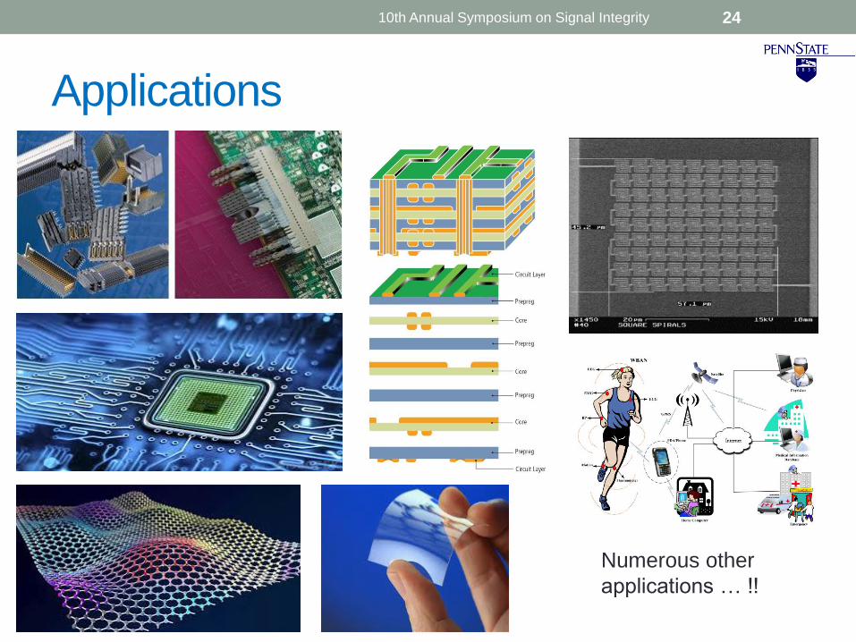
Applications
24
Numerous other
applications … !!
10th Annual Symposium on Signal Integrity

References
• [1] Kane S. Yee, “Numerical Solution of Initial Boundary Value Problems Involving Maxwell’s Equations in Isotropic
Media,” IEEE Trans. On Antennas and Propagation, vol.14, no.3, pp. 302-307, May 1966.
• [2] Jean-Pierre Berenger, “A Perfectly Matched Layer for the Absorption of Electromagnetic Waves”, Journal of
Computational Physics 114, 185-200 (1994).
• [3] Wenhua Yu, Xiaoling Yang, Yongjun Liu and Raj Mittra, Electromagnetic Simulation Techniques Based on the
FDTD Method, John Wiley & Sons, Inc., 2009.
• [4] Raj Mittra, J.N. Bringuier, “A Technique for Solving Multiscale Problems in CEM Utilizing Dipole Moments and
Macro Basis Functions,” Proceedings of the Fourth European Conference on Antennas and Propagation (EuCAP), 2010.
• [5] Raj Mittra, Jonathan Bringuier, Chiara Pelletti, Kadappan Panayappan, Ozlem Ozgun, Agostino Monorchio, “On
the Hybridization of Dipole Moment (DM) and Finite Methods for Efficient Solution of Multiscale Problems”,
Proceedings of the Fifth European Conference on Antennas and Propagation (EuCAP), 2011.
• [6] E.C. Jordan and W.L. Everitt, “Acoustic Models of Radio Antennas”, Proc. IRE, 29, 4, 186 (1941).
2510th Annual Symposium on Signal Integrity

Thank You
Questions
2610th Annual Symposium on Signal Integrity