modeling, design, and control of robotic mechanisms
TRANSCRIPT

Modeling, Design, and Control of Robotic Mechanisms
Modeling, Design, and Control of Robotic Mechanisms
Han Sung Kim
Department of Mechanical Engineering,Kyungnam University
Email: [email protected]: http://imecha.kyungnam.ac.kr
(Phone: 82-55-249-2627, Fax: 82-505-999-2160)

ContentsContents
(1) Development of Robotic Mechanisms
(2) Analysis and MATLAB Practice
(3) SimMechanics Simulation Practice
(4) Robot Control Practice
(5) Project Practice: Arduino Project, Walking Robot, Haptic Interface

Project SummaryProject Summary
Title: Design of Mechatronics System and Capstone Design Subtitle: Modeling, Design, and Control of Robotic Mechanisms Abstract:
This project is to make analytical and CAD models of robotic mechanisms (for example, industrial robots, walking robots, etc.), to design robotic mechanisms and position controller based on the models, to fabricate the robotic mechanisms and the embedded real-time controller by using xPC Target, and to do the control experiments on prototype robot system.
Project Goals:To make kinematic & dynamic models and simulations of simple robotic mechanismsTo design controller based on plant model & To implement real hardware
Lecture notes (for 15 weeks)Applicable subjects: Robotics, Mechatronics, and Capstone Design

(1) Development of Robotic Mechanisms(1) Development of Robotic Mechanisms
2-DOF/3-DOF Planar Serial Robots, 2-DOF 5-bar Closed-loop Mechanism (Type I & II), and 3-DOF 3-RRR Parallel Robot 4 DC servo motors (Maxon 20W) with one 66:1 and three 23:1 gears Use the same base platform Horizontal and vertical configurations (gravity compensation experiment) Double ball bearings are employed for better rigidity and small friction Could be used as force feedback haptic device (low gear ratio) Machine vision and vision-based control experiments
Waling Robots with 6-bar and 8-bar Legs Actuated by two DC motors and Move forward/backward/right/left Statically balanced walking robot

2-DOF Planar Serial Robot (R-R)2-DOF Planar Serial Robot (R-R)
[Horizontal Configuration] [Vertical Configuration]

3-DOF Planar Serial Robot (R-R-R)3-DOF Planar Serial Robot (R-R-R)
[Horizontal Configuration] [Vertical Configuration]
[PC CAM]

2-DOF 5-bar Closed-loop Mechanisms2-DOF 5-bar Closed-loop Mechanisms
[Type I] [Type II]
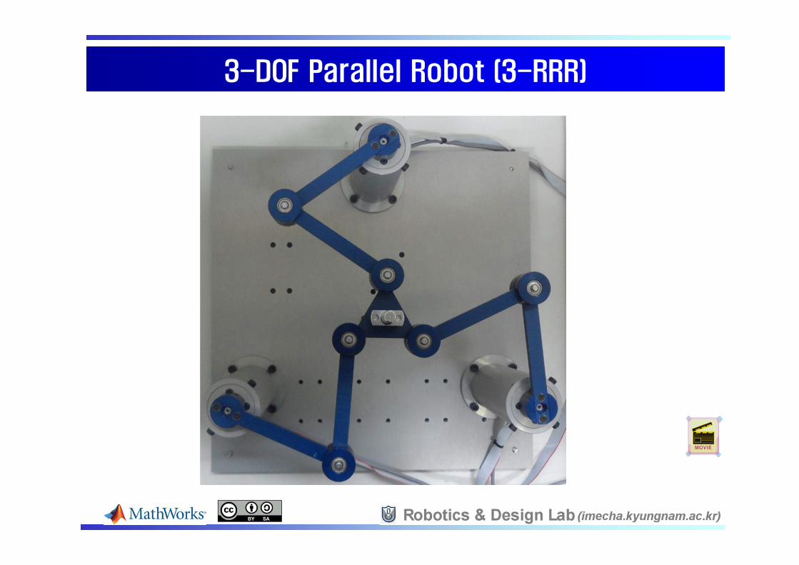
3-DOF Parallel Robot (3-RRR)3-DOF Parallel Robot (3-RRR)

Arduino ProjectsArduino Projects
[Sensor & Actuator Interface]
[2-DOF Robot Arm with Arduino Mega 2560]

Walking RobotsWalking Robots
[with 6-bar Legs] [with 8-bar Legs]

Walking RobotsWalking Robots
[DC Motor & External Power] [Servo Motor, Wireless & Battery]

(2) Analysis and MATLAB Practice(2) Analysis and MATLAB Practice
Forward & Inverse Kinematic Analysis Velocity & Statics Analysis Forward & Inverse Dynamics Analysis MATLAB Practices (MATLAB Demo)
[MATLAB Figure] [VRML Output]
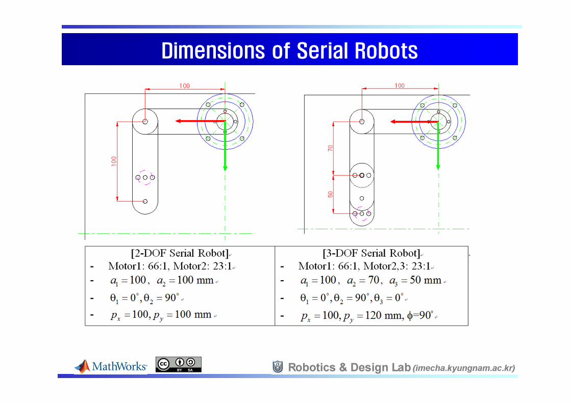
Dimensions of Serial RobotsDimensions of Serial Robots
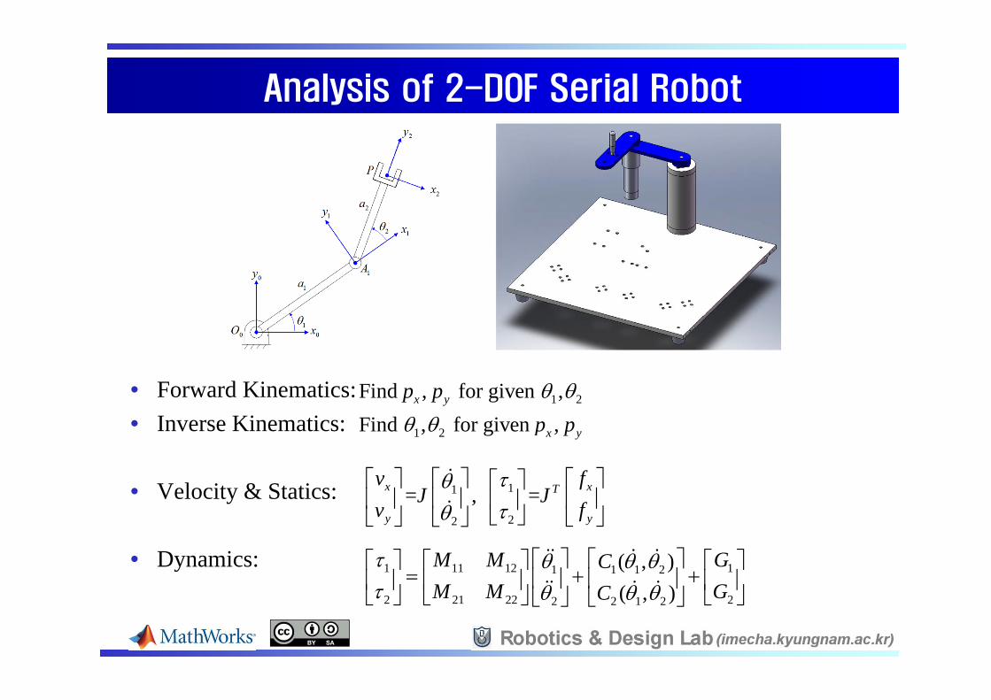
Analysis of 2-DOF Serial RobotAnalysis of 2-DOF Serial Robot
• Forward Kinematics:• Inverse Kinematics:
• Velocity & Statics:
• Dynamics:
1 2Find , for given ,x yp p
1 2Find , for given ,x yp p
11
22
= , =x xT
y y
v fJ J
v f
1 11 12 11 1 1 2
2 21 22 22 2 1 2
( , )( , )
M M GCM M GC
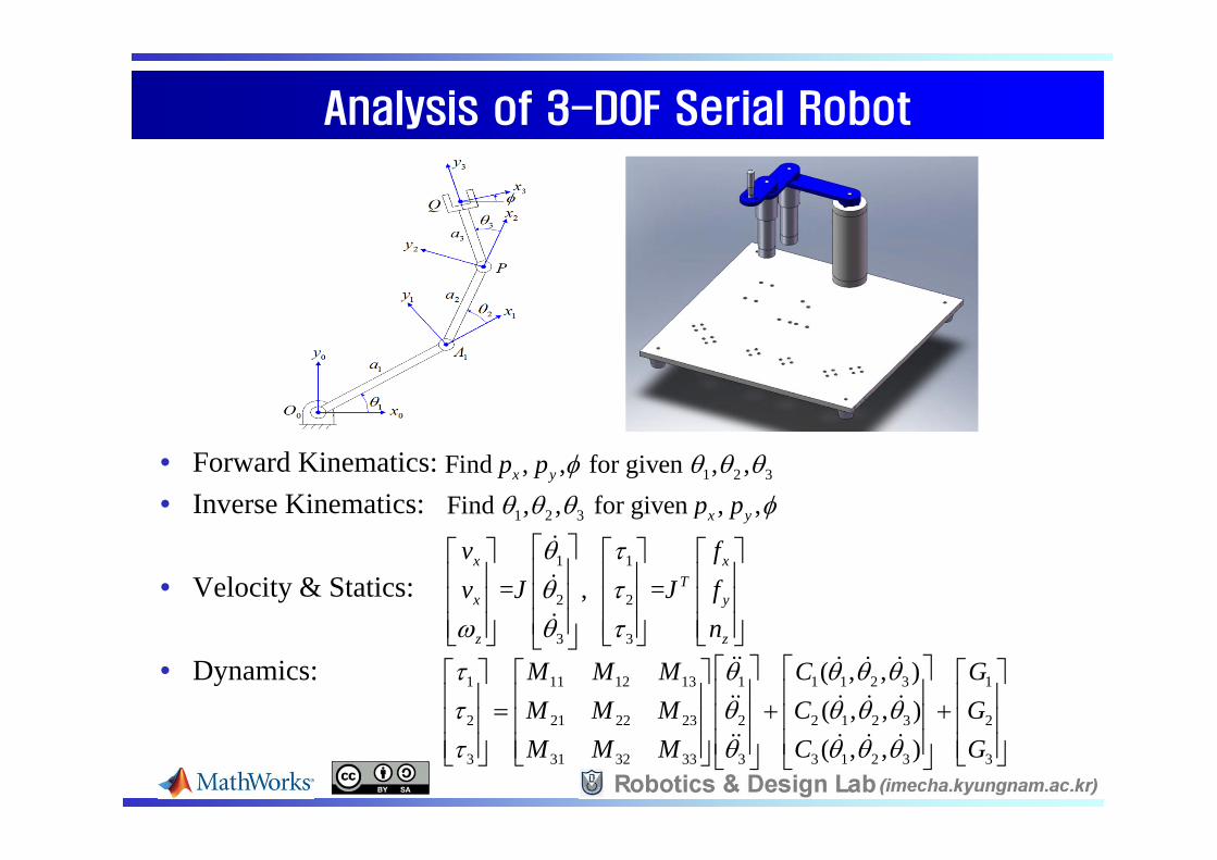
Analysis of 3-DOF Serial RobotAnalysis of 3-DOF Serial Robot
• Forward Kinematics:• Inverse Kinematics:
• Velocity & Statics:
• Dynamics:
1 2 3Find , , for given , ,x yp p
1 2 3Find , , for given , ,x yp p
1 1
2 2
3 3
= , =x x
Tx y
z z
v fv J J f
n
1 11 12 13 1 1 1 2 3 1
2 21 22 23 2 2 1 2 3 2
3 31 32 33 3 3 1 2 3 3
( , , )( , , )( , , )
M M M C GM M M C GM M M C G

Dimensions of 5-bar MechanismsDimensions of 5-bar Mechanisms
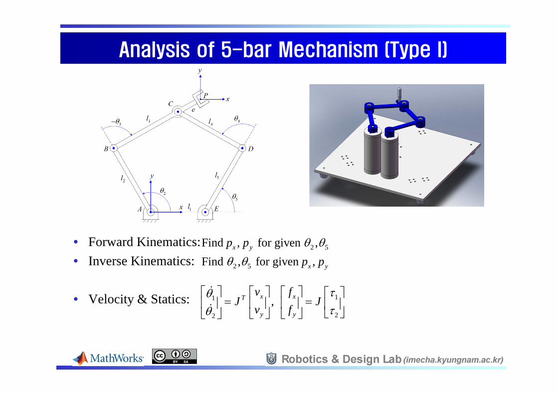
Analysis of 5-bar Mechanism (Type I)Analysis of 5-bar Mechanism (Type I)
• Forward Kinematics:• Inverse Kinematics:
• Velocity & Statics:
2 5Find , for given ,x yp p
2 5Find , for given ,x yp p
11
22
, x xT
y y
v fJ J
v f

Analysis of 5-bar Mechanism (Type II)Analysis of 5-bar Mechanism (Type II)
• Forward Kinematics:• Inverse Kinematics:
• Velocity & Statics:
2 5Find , for given ,x yp p
2 5Find , for given ,x yp p
11
22
, x xT
y y
v fJ J
v f

Dimensions of 3-DOF Parallel RobotDimensions of 3-DOF Parallel Robot
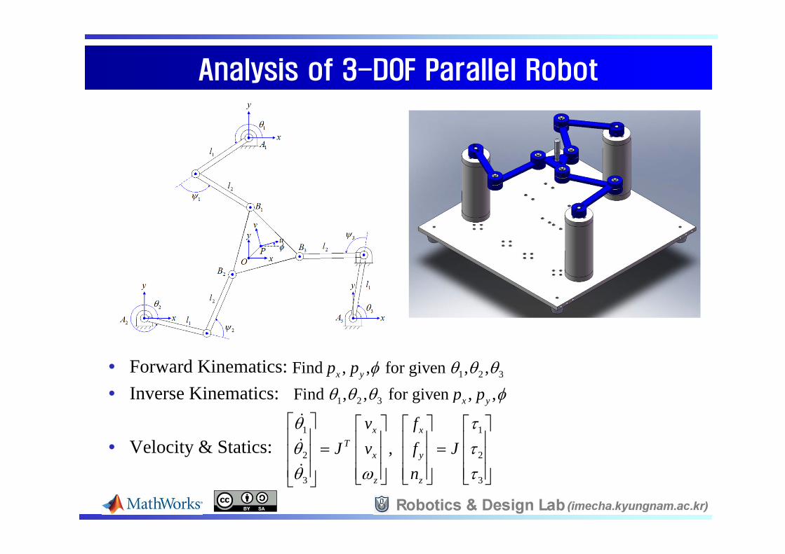
Analysis of 3-DOF Parallel RobotAnalysis of 3-DOF Parallel Robot
• Forward Kinematics:• Inverse Kinematics:
• Velocity & Statics:
1 2 3Find , , for given , ,x yp p
1 2 3Find , , for given , ,x yp p
1 1
2 2
3 3
, x x
Tx y
z z
v fJ v f J
n

[3] SimMechanics Simulation Practice[3] SimMechanics Simulation Practice
Forward Dynamics Simulation Apply forces Find motions Numerical integration (ode45)
Inverse Dynamics Simulation Specify motions (Trajectory) Find joint torques Design of actuator size Computed torque control (simple gravity compensation)
Comparing SimMechanics results with those of the Dynamics Equations and ADAMS simulations
1 11 12 11 1 1 2
2 21 22 22 2 1 2
( , )( , )
M M GCM M GC

Forward Dynamics Simulation (2-DOF Serial Robot)Forward Dynamics Simulation (2-DOF Serial Robot)
Mass(kg) Inertia(kg mm2)
CG Position(m)/from CS1
CS(m)/from World
Ground - - - [0 0 0]
Link1 0.071 89.395 [0.0373 0 0] CS1 = [0 0 0]CS2 = [0.1 0 0]
Motor 0.292 0 [0 0 0] CS1 = [0.1 0 0]CS2 = [0.1 0 0]
Link2 0.075 109.864 [0.04168 0 0] CS1 = [0.1 0 0]CS2 = [0.2 0 0]
Initial Condition: [1, 2]=[-60,0]

Inverse Dynamics Simulation (2-DOF Serial Robot)Inverse Dynamics Simulation (2-DOF Serial Robot)
Joint-space Simulation: [1, 2]=[0,0] [90,0]
[Joint Torque]
[Cubic Trajectory]

Inverse Dynamics Simulation (2-DOF Serial Robot)Inverse Dynamics Simulation (2-DOF Serial Robot)
Cartesian-space Simulation: [px, py]=[100,100] [-100,100]
[Cubic Trajectory]
[Joint Torque]

Comparison of Simulation Results (2-DOF Serial Robot)Comparison of Simulation Results (2-DOF Serial Robot)
Dynamics Equation:
ADAMS Result:
SimMechanics Result:

Inverse Dynamics Simulation (3-DOF Serial Robot)Inverse Dynamics Simulation (3-DOF Serial Robot)
Mass(kg)
Inertia(kg mm2)
CG Position(m)/from CS1
CS(m)/from World
Ground - - - [0 0 0]
Link1 0.071 89.395 [0.0373 0 0] CS1 = [0 0 0]CS2 = [0.1 0 0]
Motor2 0.292 0 [0 0 0] CS1 = [0.1 0 0]CS2 = [0.1 0 0]
Link2 0.055 38.709 [0.0236 0 0] CS1 = [0.1 0 0]CS2 = [0.17 0 0]
Motor3 0.292 0 [0 0 0] CS1 = [0.17 0 0]CS2 = [0.17 0 0]
Link3 0.05 24.587 [0.0186 0 0] CS1 = [0.17 0 0]CS2 = [0.22 0 0]
Cartesian-space Simulation: [px, py]=[100,100], =90 [-100,100] , =90

Inverse Dynamics Simulation (5-bar mechanism)Inverse Dynamics Simulation (5-bar mechanism)
Cartesian-space Simulation: px=50, py=50,
Mass(kg) Inertia(kg mm2)
CG Position(m)/from CS1
CS(m)/from World
L_Ground - - - [0 0 0]
L_Link1 0.053 110.61 [-0.025592 0.046537 0] CS1 = [0 0 0]CS2 = [-0.048187 0.087624 0]
L_Link2 0.054 120.188 [0.042537 0.026153 0]CS1 = [-0.048187 0.087624 0]CS2 = [0.037 0.140 0]CS3 = [0.060852 0.154665 0]
R_Ground - - - [0.074 0 0]
R_Link1 0.061 134.303 [0.022017 0.040035 0] CS1 = [0.074 0 0]CS2= [0.122187 0.087624 0]
R_Link2 0.045 90.992 [-0.042594 0.026188 0] CS1= [0.122187 0.087624 0]CS2 = [0.037 0.140 0]
L_Link1
L_Link2 R_Link2
R_Link1
L_Ground R_Ground

Inverse Dynamics Simulation (5-bar mechanism, Type I)Inverse Dynamics Simulation (5-bar mechanism, Type I)
[px move]
[py move]

Inverse Dynamics Simulation (5-bar mechanism, Type II)Inverse Dynamics Simulation (5-bar mechanism, Type II)
[px move]
[py move]

Inverse Dynamics Simulation (3-DOF Parallel Robot)Inverse Dynamics Simulation (3-DOF Parallel Robot)
Mass(kg)
Inertia(kg mm2)
CG Position(m)/from CS1
CS(m)/from World
Ground1 - - - [0 0.15 0]
Link1_1 0.053 110.621 [-0.043452 -0.030538 0]
CS1=[0 0.15 0]CS2=[-0.081818 0.092497 0]
Link1_2 0.045 90992 [0.040909 -0.028749 0]
CS1=[-0.081818 0.092497 0]CS2=[0 0.035 0]
Ground2 - - - [-0.1299 -0.075 0]
Link2_1 0.053 110.621 [0.048173 -0.022361 0]
CS1=[-0.1299 -0.075 0]CS2=[-0.039196 -0.117104 0]
Link2_2 0.045 90.992 [0.0044425 0.049802 0]
CS1=[-0.039196 -0.117104 0]CS2=[-0.03011 -0.0175 0]
Ground3 - - - [0.129902 -0.074997 0]
Link3_1 0.053 110.621 [-0.0047204 0.0528997 0]
CS1=[0.129902 -0.074997 0]CS2=[0.121013 0.024607 0]
Link3_2 0.045 90.992 [-0.0453515 -0.0210535 0
CS1=[0.121013 0.024607 0]CS2=[0.030311 -0.0175 0]
Mo-Pl 0.081 46.643 [0 0 0]/from World
CS1=[0 0.035 0]CS2=[-0.03011 -0.0175 0]CS3=[0.030311 -0.0175 0]

Inverse Dynamics Simulation (3-DOF Parallel Robot)Inverse Dynamics Simulation (3-DOF Parallel Robot)
Cartesian-space Simulation: px=50, py=50,
[px move]
[py move]

[4] Robot Control Practice[4] Robot Control Practice
Introduction to xPC Target & speedgoat controller Design of speedgoat Controller Robot Control Practice Hardware Test Control of DC servo motors (In Joint-space) Simple PTP Control (In Cartesian-space) Trajectory Control (In Cartesian-space) Gravity Compensation (In Cartesian-space)

Introduction to xPC TargetIntroduction to xPC Target
[Host PC]Windows
Non Real-time
[Target PC]xPC Target
Real-time Kernel
TCP/IPI/O
[Hardware]Robots, Mechatronics
SimulinkProgramming
C-codeGeneration
.dlmexecutable
on xPC Target
Real-timeWorkshop C-Compiler
(Simulink Coder)

Introduction to speedgoat ControllerIntroduction to speedgoat Controller
speedgoat Education real-time target machine Intel Celeron M 1GHz, 1GB IDE flash drive, 24V DC I/O Slots: 2 (IO101 & IO311) IO101 (fixed DAQ package): 16-ch AI (16 bit, differential), 8-ch AO, 8-
ch DI, 8-ch DO IO311 (Motion Control FPGA package): 64 TTL I/O, 24k logic cells,
fixed set of 3-ch PWM, 3-ch Encoder, DIO Supported xPC target drivers

Design of speedgoat ControllerDesign of speedgoat Controller
Real-time Controllers:(Two types of DC amplifiers)

Design of speedgoat ControllerDesign of speedgoat Controller
[Front view]
[Side view][Top view]
IO101IO311
Maxon Amp
Ch1 Ch2 Ch3
PWM Amp
Ch1 Ch2 Ch3

Design of speedgoat ControllerDesign of speedgoat Controller
M+ M- Vcc Gnd31 42 7 8
-Set +Set
PWM DIR BRK GND
M+ M-
GND
24V
GND AO1
46 12
M+ M- Vcc Gnd31 42 7 8
-Set +Set M+ M- Vcc Gnd31 42 7 8
-Set +Set
GND AO2 GND AO3
47 13 48 14
1 37PWM1 DIO7
40DIO10
PWM DIR BRK GND
M+ M-
GND
24V
4 38PWM2 DIO8
41DIO11
PWM DIR BRK GND
M+ M-
GND
24V
7 39PWM3 DIO9
42DIO12
17GND
Q1-A Q1-B
14 15Q2-A Q2-B
19 20Q3-A Q3-B
22 23GND
18
6 8A B
2VCC
3GND
6 8A B
2VCC
3GND
6 8A B
2VCC
3GND
[IO101]
[MAXON AMP1] [AMP2] [AMP3]
[PWM AMP1] [AMP2] [AMP3]
[IO311]
[ENC3][ENC2][ENC1]
GND
5V
[5V DCPOWER]
GND
24V
[24V DCPOWER]
Design of speedgoat ControllerDesign of speedgoat Controller
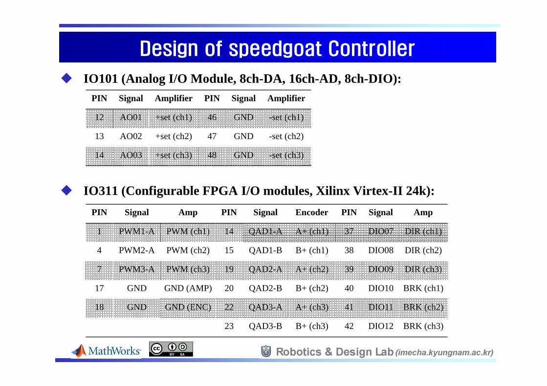
IO101 (Analog I/O Module, 8ch-DA, 16ch-AD, 8ch-DIO):
IO311 (Configurable FPGA I/O modules, Xilinx Virtex-II 24k):
PIN Signal Amplifier PIN Signal Amplifier
12 AO01 +set (ch1) 46 GND -set (ch1)
13 AO02 +set (ch2) 47 GND -set (ch2)
14 AO03 +set (ch3) 48 GND -set (ch3)
PIN Signal Amp PIN Signal Encoder PIN Signal Amp
1 PWM1-A PWM (ch1) 14 QAD1-A A+ (ch1) 37 DIO07 DIR (ch1)
4 PWM2-A PWM (ch2) 15 QAD1-B B+ (ch1) 38 DIO08 DIR (ch2)
7 PWM3-A PWM (ch3) 19 QAD2-A A+ (ch2) 39 DIO09 DIR (ch3)
17 GND GND (AMP) 20 QAD2-B B+ (ch2) 40 DIO10 BRK (ch1)
18 GND GND (ENC) 22 QAD3-A A+ (ch3) 41 DIO11 BRK (ch2)
23 QAD3-B B+ (ch3) 42 DIO12 BRK (ch3)

Design of speedgoat ControllerDesign of speedgoat Controller
Maxon LSC 30/2 amplifier (24V, 2A):
LMD18200 PWM amplifier (24V, 3A):
DA+GND
PWM DIR BREAK GND
+24V GND
M+ M- Maxon Motor (20W)• 66:1 Geared motor:
Tmax=3.1 Nm• 23:1 Geared motor
Tmax=1.1 Nm• Encoder: 500 lines/rev

Robot Control Practice: Hardware TestRobot Control Practice: Hardware Test
3-ch DA output, 3-ch PWM output, 6-ch Digital output, 3-ch Encoder input Sampling time: 1mse, external mode
100
V6
100
V5
100
V4
10
V3
10
V2
10
V1
0
Slider Gain6
0
Slider Gain5
0
Slider Gain4
0
Slider Gain3
0
Slider Gain2
0
Slider Gain1
ZOH
Rate Transition2
ZOH
Rate Transition1
ZOH
Rate Transition
-K-
R2D
In1
PWM Generation1
Init HW
Out1
Encoder
0
0
0
Display2
0
0
0
Display1
0
0
0
DisplayIn1
DA
3
3
3 3
3
33
33
33

Robot Control Practice: DC motor controlRobot Control Practice: DC motor control
Control of DC motors for step and cubic trajectory inputs (Joint-space control)
0 0.1 0.2 0.3 0.4 0.5 0.6 0.7 0.8 0.9 10
2
4
time [sec]
th [d
eg]
0 0.1 0.2 0.3 0.4 0.5 0.6 0.7 0.8 0.9 1-2
0
2
time [sec]
err [
deg]
0 0.1 0.2 0.3 0.4 0.5 0.6 0.7 0.8 0.9 1-100
0
100
time [sec]
U [V
]
0.1 0.2 0.3 0.4 0.5 0.6 0.7 0.8 0.9 10
5
time [sec]
th [d
eg]
0.1 0.2 0.3 0.4 0.5 0.6 0.7 0.8 0.9 10
0.05
0.1
time [sec]er
r [de
g]
0.1 0.2 0.3 0.4 0.5 0.6 0.7 0.8 0.9 1-0.5
0
0.5
time [sec]
U [V
]
DC servo motor with 66:1 gear (kp=150, kd=1)
[step input] [cubic trajectory input]

Robot Control Practice: PTP controlRobot Control Practice: PTP control
2-DOF Serial Robot: (M1) kp=200, kd=1.5, (M2) kp=160, kd=1.2 Cubic Trajectory: [px, py]=[100,120] [-100,120]
0.5 1 1.5 2 2.5 3 3.5 4 4.5 5 5.5 6-100
-50
0
50
100
time [sec]
xd [m
m]
0.5 1 1.5 2 2.5 3 3.5 4 4.5 5 5.5 60
50
100
150
time [sec]
th [d
eg]
0.5 1 1.5 2 2.5 3 3.5 4 4.5 5 5.5 6-0.1
0
0.1
0.2
0.3
time [sec]
err [
deg]

Robot Control Practice: PTP controlRobot Control Practice: PTP control
3-DOF Serial Robot: (M1) kp=200, kd=1.5, (M2,3) kp=160, kd=1.2 Cubic Trajectory: [px, py]=[100,120], 90 deg [-100,120], 90 deg
5
tsec
(pi/180)*[0,90,0]'
enc_offset
[-200,0,0*D2R]'
dx
dx
tsec
xdfcn
Trajectory Function
In1 Out1
PID Subsystemxd
thd
w_indexfcn
Inverse Kinematics
[w_index]
Goto5
[xd]
Goto4[u]
Goto3
[err]
Goto2
[tha]
Goto1
[thd]
Goto
Out1
Encoder
In1
DA
3
33
3
3
3
3
3
33
3
3
3
3
3
3
3
33
0.5 1 1.5 2 2.5 3 3.5 4 4.5 5 5.5 6-100
0
100
200
time [sec]
xd [m
m]
0.5 1 1.5 2 2.5 3 3.5 4 4.5 5 5.5 6-200
-100
0
100
200
time [sec]
th [d
eg]
0.5 1 1.5 2 2.5 3 3.5 4 4.5 5 5.5 6-0.2
0
0.2
0.4
0.6
time [sec]
err [
deg]

Robot Control Practice: PTP controlRobot Control Practice: PTP control
5-bar Mechanism (Type I) : (M1,2) kp=160, kd=1.2 Cubic Trajectory: px=50, py=50
2
tsec
(pi/180)*[120,60]'
enc_offset
(50 0)
dx
dx
tsec
xdfcn
Trajectory Function
In1 Out1
PID Subsystemxd
thd
w_indexfcn
Inverse Kinematics
[w_index]
Goto5
[xd]
Goto4[u]
Goto3
[err]
Goto2
[tha]
Goto1
[thd]
Goto
Out1
Encoder
In1
DA
2
2
22
2
2
2
2
22
2
2
2
2
2
2
2
22
0.2 0.4 0.6 0.8 1 1.2 1.4 1.6 1.8 20
100
200
time [sec]
xd [m
m]
0.2 0.4 0.6 0.8 1 1.2 1.4 1.6 1.8 20
100
200
time [sec]
th [d
eg]
0.2 0.4 0.6 0.8 1 1.2 1.4 1.6 1.8 2-0.2
0
0.2
time [sec]
err [
deg]
1
0.2 0.4 0.6 0.8 1 1.2 1.4 1.6 1.8 20
200
400
time [sec]
xd [m
m]
0.2 0.4 0.6 0.8 1 1.2 1.4 1.6 1.8 250
100
150
time [sec]
th [d
eg]
0.2 0.4 0.6 0.8 1 1.2 1.4 1.6 1.8 2-0.2
0
0.2
time [sec]
err [
deg]
1[X move] [Y move]

Robot Control Practice: PTP controlRobot Control Practice: PTP control
3-DOF Parallel Robot: (M1,2,3) kp=160, kd=1.2 Cubic Trajectory: px=50, py=50
2
tsec
(pi/180)*[-144.9004,-24.9004,95.0996]'
enc_offset
[50,0,0*D2R]'
dx
dx
tsec
xdfcn
Trajectory Function
In1 Out1
PID Subsystemxd
thd
w_indexfcn
Inverse Kinematics
[w_index]
Goto5
[xd]
Goto4[u]
Goto3
[err]
Goto2
[tha]
Goto1
[thd]
Goto
Out1
Encoder
In1
DA
3
33
3
3
3
3
3
33
3
3
3
3
3
3
3
33
0.2 0.4 0.6 0.8 1 1.2 1.4 1.6 1.8 20
50
time [sec]
xd [m
m]
0.2 0.4 0.6 0.8 1 1.2 1.4 1.6 1.8 2-200
0
200
time [sec]
th [d
eg]
0.2 0.4 0.6 0.8 1 1.2 1.4 1.6 1.8 2-0.5
0
0.5
time [sec]
err [
deg]
0.2 0.4 0.6 0.8 1 1.2 1.4 1.6 1.8 20
50
time [sec]
xd [m
m]
0.2 0.4 0.6 0.8 1 1.2 1.4 1.6 1.8 2-200
0
200
time [sec]th
[deg
]
0.2 0.4 0.6 0.8 1 1.2 1.4 1.6 1.8 2-0.5
0
0.5
time [sec]
err [
deg]
[X move] [Y move]

Robot Control Practice: TrajectoryRobot Control Practice: Trajectory
Trajectory Generation (similar to G-code)
0 4P , P
3P
1P[-200, 0]
2P
x
y
[0, 0]
[0, 40][-200, 40]
5P ( 30 ) 6P ( 30 )
7P ( 0 )
% 3-DOF SKM %G01 X0 Y0 W0 L80 A30% -X MoveG01 X-200 Y0 W0S00 T0.1% +Y MoveG01 X-200 Y40 W0S00 T0.1% +X MoveG01 X0 Y40 W0S00 T0.1% -Y MoveG01 X0 Y0 W0S00 T0.1% +ANG %G01 X0 Y0 W30S00 T0.1% -ANG %G01 X0 Y0 W-30S00 T0.1% HOME %G01 X0 Y0 W0S00 T0.1M02
[Grammar]% : notesG01 : ptp move (by cubic polynomial)Format: X Y W L A[mm] [mm] [deg] [mm/s] [deg/s]S00 T : set holding time in secM02 : script end
0 5 10 15-200
0
200
Time [sec]
pos
[mm
]
0 5 10 15-100
0
100
Time [sec]
vel [
mm
/s]
0 5 10 15-500
0
500
Time [sec]
acc
[mm
/s2 ]
0 5 10 15-50
0
50
Time [sec]
ang
[deg
]
0 5 10 15-50
0
50
Time [sec]
omeg
a [d
eg/s
]
0 5 10 15-200
0
200
Time [sec]
alph
a [d
eg/s
2 ]

Robot Control Practice: TrajectoryRobot Control Practice: Trajectory
2-DOF Serial Robot:
0 2 4 6 8 10 12-100
0
100
200
time [sec]
xd [m
m]
0 2 4 6 8 10 120
50
100
150
time [sec]
th [d
eg]
0 2 4 6 8 10 12-0.5
0
0.5
time [sec]
err [
deg]
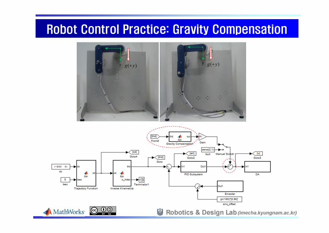
Robot Control Practice: Gravity CompensationRobot Control Practice: Gravity Compensation

[5-1] Arduino Interface: Arduino Mega 2560[5-1] Arduino Interface: Arduino Mega 2560
Arduino Mega 2560 ATmega 2560: 16MHz, 256kB Flash, 54-DIO, 14-PWM, 16-AI, 4-
UART, USB connector Supported I/O drivers: AI, DI, DO, AI, PWM, Servo Read/Write, Serial
Receive/Transmit MathWorks webpage:
http://www.mathworks.co.kr/products/simulink/simulink-targets/

[5-2] Mechatronics Practice[5-2] Mechatronics Practice
Analog Sensor:[Inputs: IR, Switch, Mic, Tilt CdS, Remote, Ouputs: LED, Buzzer]
ON/OFF Type:
[IR, Pot, Keypad]

[5-2] Mechatronics Practice[5-2] Mechatronics Practice
[Dynamixel (32:1, 254:1) DC motor, Pot]
DC Motor:
[PWM Amp]
[Connection]
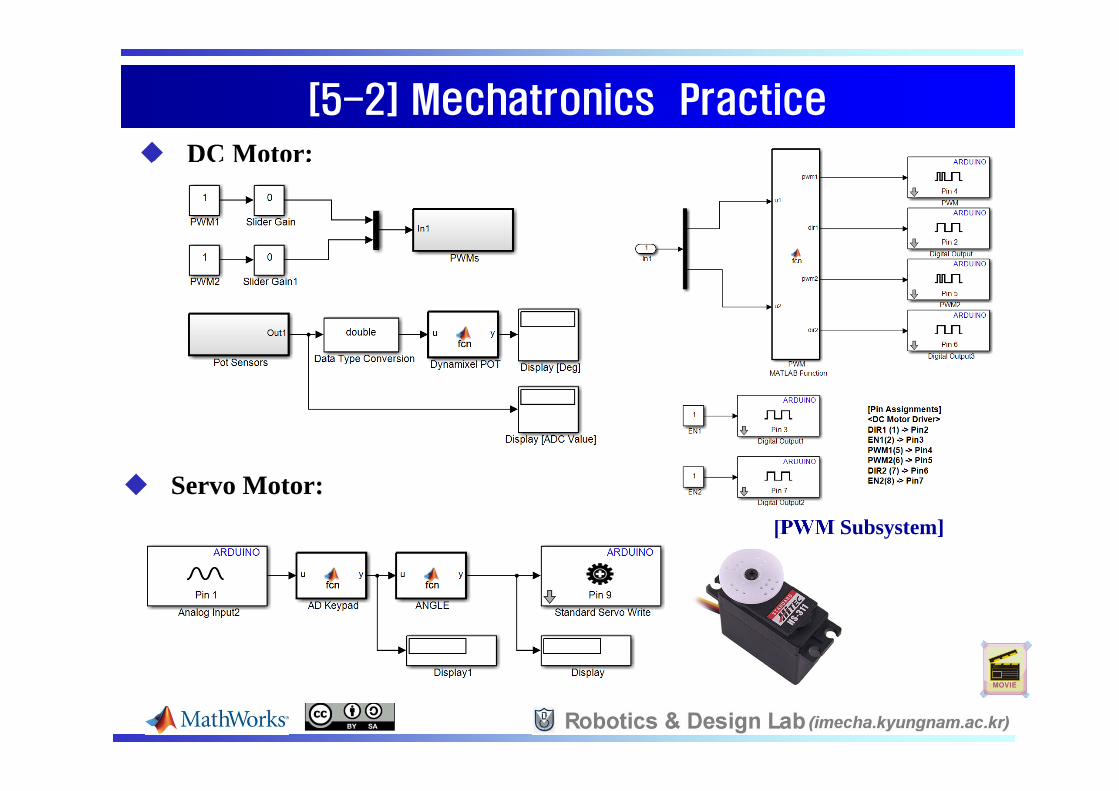
[5-2] Mechatronics Practice[5-2] Mechatronics Practice
DC Motor:
[PWM Subsystem]
Servo Motor:

[5-3] PID Control Practice[5-3] PID Control Practice
PID Control (10msec):
2 2.5 3 3.5 4 4.5 5 5.5 6 6.50
20
40
60
80
100
120
time [sec]
thd
& th
a [d
eg]
2 3 4 5 6 7 80
10
20
30
40
50
60
70
80
90
100
time [sec]th
d &
tha
[deg
]
[Kp=300, Kd=0, Ki=0] [Kp=300, Kd=12, Ki=0] [Kp=300, Kd=12, Ki=100]
2 2.5 3 3.5 4 4.5 5 5.5 6 6.5 70
50
100
150
time [sec]
thd
& th
a [d
eg]

[5-4] 2-DOF Robot Arm Project[5-4] 2-DOF Robot Arm Project
2-DOF Robot Arm with Keypad Control:Forward Kinematics: K0+th1, K4-th1, K1+th2, K5-th2Inverse Kinematics: K2+x, K6-x, K3+y, K7-y

[5-5] Walking Robot[5-5] Walking Robot
2-ch PWM AMP
Arduino Mega 2560
3 IR Sensors

Arduino Interface: Arduino Mega 2560Arduino Interface: Arduino Mega 2560
Arduino Mega 2560 ATmega 2560: 16MHz, 256kB Flash, 54-DIO, 14-PWM, 16-AI, 4-
UART, USB connector Supported I/O drivers: AI, DI, DO, AI, PWM, Servo Read/Write, Serial
Receive/Transmit MathWorks webpage:
http://www.mathworks.co.kr/products/simulink/simulink-targets/

Arduino Interface: PartsArduino Interface: Parts
DC Motor Amplifier(AM-DC2-2D) (2ch, 2A, 5~45V)
Geared DC Motor (60RPM, 3.5kgf.cm at DC 6V)

Arduino Interface: ConnectionArduino Interface: Connection
225V 5V
2324 2526 27
Gnd Gnd
3 2[PWM]
[DIG
ITA
L]
5V Gnd[Power]
[USB]
[POWER]
31 2
45 67 89 10
V+V-
M+ M- M+ M-
[Motor1] [Motor2]
[9V DCPOWER]
GND
9V
[Arduino Mega 2560]
[PWM AMP]
Gnd Vcc
[IR Sensor 3]Out
Gnd Vcc
[IRSensor 1]Out
Gnd Vcc
[IR Sensor 2]Out
28 29
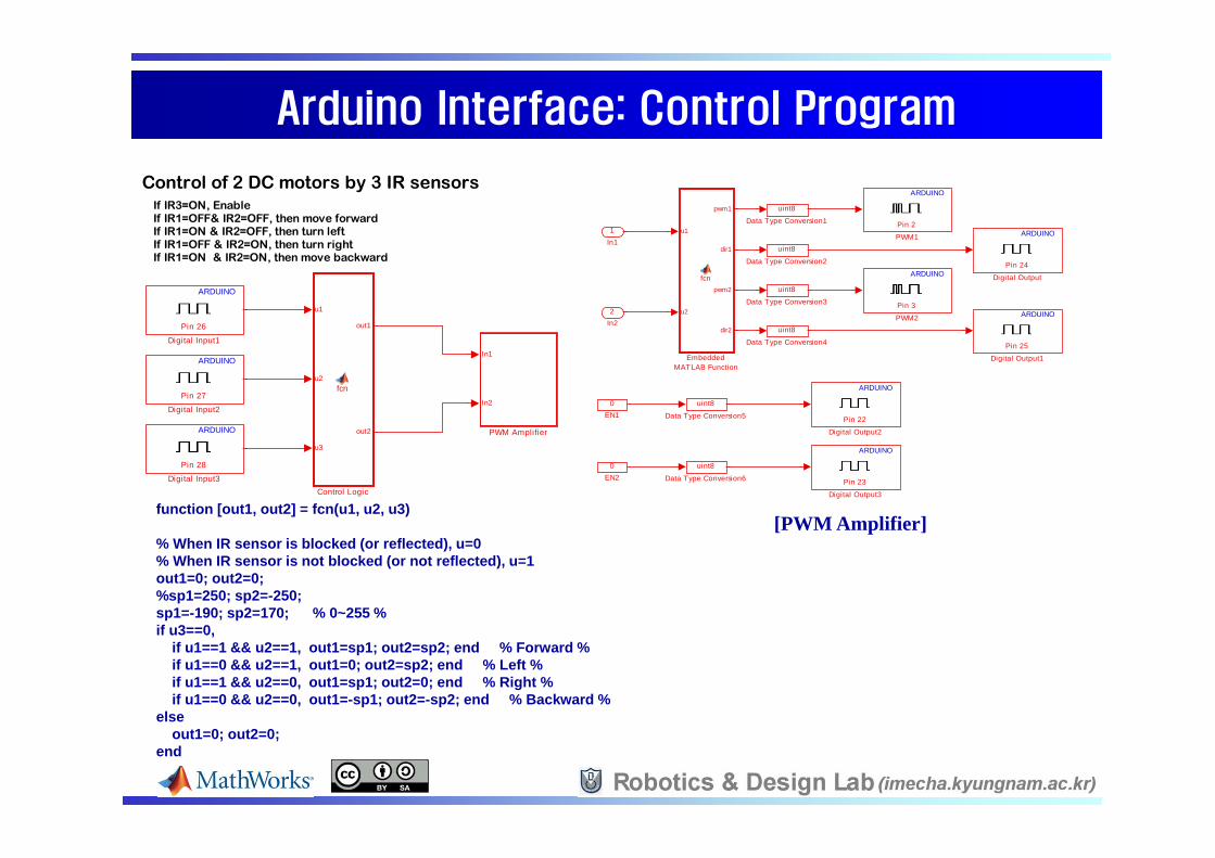
Arduino Interface: Control ProgramArduino Interface: Control Program
Control of 2 DC motors by 3 IR sensorsIf IR3=ON, EnableIf IR1=OFF& IR2=OFF, then move forwardIf IR1=ON & IR2=OFF, then turn leftIf IR1=OFF & IR2=ON, then turn rightIf IR1=ON & IR2=ON, then move backward
In1
In2
PWM Amplifier
Pin 28
ARDUINO
Digital Input3
Pin 27
ARDUINO
Digital Input2
Pin 26
ARDUINO
Digital Input1
u1
u2
u3
out1
out2
fcn
Control Logic
Pin 3
ARDUINO
PWM2
Pin 2
ARDUINO
PWM1u1
u2
pwm1
dir1
pwm2
dir2
fcn
EmbeddedMATLAB Function
0EN2
0EN1
Pin 23
ARDUINO
Digital Output3
Pin 22
ARDUINO
Digital Output2
Pin 25
ARDUINO
Digital Output1
Pin 24
ARDUINO
Digital Output
uint8
Data Type Conversion6
uint8
Data Type Conversion5
uint8
Data Type Conversion4
uint8
Data Type Conversion3
uint8
Data Type Conversion2
uint8
Data Type Conversion1
2In2
1In1
[PWM Amplifier]function [out1, out2] = fcn(u1, u2, u3)
% When IR sensor is blocked (or reflected), u=0% When IR sensor is not blocked (or not reflected), u=1out1=0; out2=0;%sp1=250; sp2=-250; sp1=-190; sp2=170; % 0~255 %if u3==0,
if u1==1 && u2==1, out1=sp1; out2=sp2; end % Forward %if u1==0 && u2==1, out1=0; out2=sp2; end % Left %if u1==1 && u2==0, out1=sp1; out2=0; end % Right %if u1==0 && u2==0, out1=-sp1; out2=-sp2; end % Backward %
elseout1=0; out2=0;
end

6-bar Leg Mechanisms6-bar Leg Mechanisms
x
y
22Z
1Z
3Z
5Z4Z
6Z7Z
8Z
12C23C
34C
14C
57C
67C
Z1 Z2 Z3 Z4 Z5 Z6 Z7 Z845 15 37.5 37.5 60 60 37.5 22.5
[6-bar mechanism]
[3-D Modeling]
[SimMechanics]-150 -100 -50 0 50 100 150
-150
-100
-50
0
x-axis
y-ax
is
[MATLAB Simulation]

-150 -100 -50 0 50 100 150-150
-100
-50
0
50
x-axis
y-ax
is
8-bar Leg Mechanisms8-bar Leg Mechanisms
[8-bar mechanism (Theo mechanism)]
[3-D Modeling]
[SimMechanics] [MATLAB Simulation]
x
y
2
2Z1Z
3Z
5Z
4Z
6Z
7Z
8Z12C
23C
34C
14C
78C
11,12C
9Z
11Z 12Z
5Z
56C9,10C
Z1 Z2 Z3 Z4 Z5 Z6 Z7 Z8 Z9 Z10 Z11 Z1290 28 128 83 128 83 115 83 83 83 166 144

Walking Robot PrototypesWalking Robot Prototypes
[6-bar Legs] [8-bar Legs]
Operated by two DC motors and Move forward/backward/right/left Statically balanced walking robot

[5-6] Haptic Interface[5-6] Haptic Interface
2-DOF Parallel-type Haptic Device Forward kinematics module Force-Reflecting module VRML graphic module
[Haptic Device] [Virtual Environment]
position
force

[5-7] PC-based Controller with xPC Target[5-7] PC-based Controller with xPC Target
[PC-based,DAQ-based]
[FPGA-based][DSP-based]
[PC-104] [speedgoat] [NI PXI with DAQs] [AC Motor Drivers]
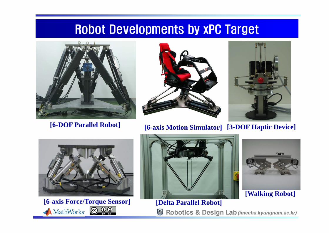
Robot Developments by xPC TargetRobot Developments by xPC Target
[6-DOF Parallel Robot] [6-axis Motion Simulator] [3-DOF Haptic Device]
[6-axis Force/Torque Sensor] [Delta Parallel Robot][Walking Robot]

[6] Conclusions[6] Conclusions
This hand-on notes can be used partially or fully in Robotics, Control Design, Mechatronics system, and Capstone Design.
The hand-on notes with drawings and MATLAB & Simulink examples will be published at the following website. http://imecha.kyungnam.ac.kr/rndlab
More project practices will be developed.