modeling of human movement for the generation of humanoid
TRANSCRIPT
HAL Id: tel-00538705https://tel.archives-ouvertes.fr/tel-00538705
Submitted on 23 Nov 2010
HAL is a multi-disciplinary open accessarchive for the deposit and dissemination of sci-entific research documents, whether they are pub-lished or not. The documents may come fromteaching and research institutions in France orabroad, or from public or private research centers.
L’archive ouverte pluridisciplinaire HAL, estdestinée au dépôt et à la diffusion de documentsscientifiques de niveau recherche, publiés ou non,émanant des établissements d’enseignement et derecherche français ou étrangers, des laboratoirespublics ou privés.
Modeling of human movement for the generation ofhumanoid robot motion
Manish Narsipura Sreeniva
To cite this version:Manish Narsipura Sreeniva. Modeling of human movement for the generation of humanoid robotmotion. Automatic. Institut National Polytechnique de Toulouse - INPT, 2010. English. �tel-00538705�

INSTITUT NATIONAL POLYTECHNIQUE DE TOULOUSE
ECOLE DOCTORALE SYSTEMES
THESE
pour obtenir le grade de
Doctorat de l’universite de Toulouse
delivre par Institut National Polytechnique de Toulouse
Specialite: Systemes Informatiques Critiques
presentee et soutenue le 21 September 2010
Modeling of human movement for the generation
of humanoid robot motion
Manish SREENIVASA
Directeurs de These
M. Philippe Soueres, M. Jean-Paul Laumond
Preparee au Laboratoire d’Analyse et d’Architecture des Systemes
Jury
M. Sethu VIJAYAKUMAR Rapporteur
M. Vincent HAYWARD Rapporteur
M. Alain BERTHOZ Examinateur
Mm. Katja MOMBAUR Examinateur


Dedicated to the love
across four generations

Abstract
Humanoid robotics is coming of age with faster and more agile robots. To compliment the
physical complexity of humanoid robots, the robotics algorithms being developed to derive
their motion have also become progressively complex. The work in this thesis spans across
two research fields, human neuroscience and humanoid robotics, and brings some ideas from
the former to aid the latter. By exploring the anthropological link between the structure of a
human and that of a humanoid robot we aim to guide conventional robotics methods like local
optimization and task-based inverse kinematics towards more realistic human-like solutions.
First, we look at dynamic manipulation of human hand trajectories while playing with a
yoyo. By recording human yoyo playing, we identify the control scheme used as well as a
detailed dynamic model of the hand-yoyo system. With the aid of optimization methods, this
model is then used to implement stable yoyo-playing within the kinematic and dynamic limits
of the humanoid robot HRP-2.
The thesis then extends its focus to human and humanoid locomotion. We take inspiration
from human neuroscience research on the role of the head in human walking and implement
a humanoid robotics analogy to this. By allowing a user to steer the head of a humanoid,
we develop a control method to generate deliberative whole-body humanoid motion including
stepping, purely as a consequence of the head movement.
This idea of understanding locomotion as a consequence of reaching a goal is extended
in the final study where we look at human motion in more detail. Here, we aim to draw
a link between “invariants” in neuroscience and “tasks” in humanoid robotics. We record
and extract stereotypical characteristics of human movements during a walking and grasping
task. These results are then normalized and generalized such that they can be regenerated for
other anthropomorphic figures with different kinematic limits than that of humans. The final
experiments implement a generalized stack of tasks that can generate realistic walking and
grasping motion for the humanoid HRP-2.
The general contribution of this thesis is in showing that while motion planning for
humanoid robots can be tackled by classical methods of robotics, the production of realistic
movements necessitate the combination of these methods with the systematic and formal
observation of human behavior.


Resume
La robotique humanoide arrive a maturite avec des robots plus rapides et plus precis. Pour
faire face a la complexite mecanique, la recherche a commence a regarder au-dela du cadre
habituel de la robotique, vers les sciences de la vie, afin de mieux organiser le controle du
mouvement. Cette these explore le lien entre mouvement humain et le controle des systemes
anthropomorphes tels que les robots humanoides.
Tout d’abord, en utilisant des methodes classiques de la robotique, telles que l’optimisation,
nous etudions les principes qui sont a la base de mouvements repetitifs humains, tels que
ceux effectues lorsqu’on joue au yoyo. Nous nous concentrons ensuite sur la locomotion en
nous inspirant de resultats en neurosciences qui mettent en evidence le role de la tete dans
la marche humaine. En developpant une interface permettant a un utilisateur de commander
la tete du robot, nous proposons une methode de controle du mouvement corps-complet d’un
robot humanoide, incluant la production de pas et permettant au corps de suivre le mouvement
de la tete.
Cette idee est poursuivie dans l’etude finale dans laquelle nous analysons la locomotion
de sujets humains, dirigee vers une cible, afin d’extraire des caracteristiques du mouvement
sous forme invariants. En faisant le lien entre la notion “d’invariant” en neurosciences et celle
de “tache cinematique” en robotique humanoide, nous developpons une methode pour produire
une locomotion realiste pour d’autres systemes anthropomorphes. Dans ce cas, les resultats sont
illustres sur le robot humanoide HRP2 du LAAS-CNRS.
La contribution generale de cette these est de montrer que, bien que la planification
de mouvement pour les robots humanoides peut etre traitee par des methodes classiques
de robotique, la production de mouvements realistes necessite de combiner ces methodes a
l’observation systematique et formelle du comportement humain.

Acknowledgements
As the culmination of several years of (sometimes) hard work, this thesis would not be
complete without acknowledging a long list of people who made it possible.
This thesis was conducted within the French ANR project Locanthrope and I gratefully
acknowledge their funding to this end. I am also grateful to the reviewers and jury of my thesis
committee. Their insight and commentary helped significantly improve the quality and clarity
of the final document.
My first gratitude goes towards my thesis supervisors Philippe Soueres and Jean-Paul
Laumond. Apart from their guidance on vital scientific and technical topics, I have also learned
what it means, and what it takes, to allow a student to nurture his/her own creativity. I hope
that someday I will be able to provide that level of guidance, freedom and support to someone
else. I have been very lucky to have the very best of teachers throughout my career, and for this
I would like to also acknowledge Katja Mombaur, Jan Souman, Ilja Frissen, Marc Ernst and
Heinrich Bulthoff.
A special mention is reserved for Alessandro de Luca who recommended me to Jean-Paul,
and recommended Jean-Paul to me. Without that vital step I would not be at my current position.
Throughout my thesis, I never made a distinction between work and play.. indeed this was
not even necessary. There are a small number of very crazy people I have to thank for this.
The PhD students of the group Gepetto and RIA have been truly legen...wait for it.. dary,
and the camaraderie that we shared would be sorely missed. I express a warm and heartfelt
wuzzzgoinonnn to ; Sebastien the New-Yorker from Paris, Mathieu the Queen of Everything,
Alireza the Master of Everything, Anh the Ladies-Man I, Oussama the Magician Musician,
Minh the Real Vietnamese Tonic, Francisco the Mexican Tornado, Sovan the (only) Sober
Rocker, David the Eating (and cooking) Machine, Layale the Life of the Party, Panos the Ladies-
Man II, Brice the (no more) Neanderthal, Muhammad Ali the Wise, Assia the Eternal Giggler,
Mokhtar the Ice Hockey Player, Xavier the Rallyist, Doung the Rising Hope of Gepetto, Thomas
the Diplomat, Amit Pandey, Sabita Pandey, Christophe Halgand, Antonio Elkhoury and Carlos
Hernandez.
A grateful thanks to all the past and present senior members of RIA ; Eiichi Yoshida, Nicolas
Mansard, Florent Lamiraux, Michel Taix, Joan Sola and Mitsuharu Morisawa... they can party

Chapter 0 · · § 0.0
as hard as their students and it has been a pleasure working with them. Special thanks are
due to Anthony Mallet, for tolerating my frequently crappy programming code, for all the
conversations, and for all the cigarettes I “borrowed” from him.
The big smoky burnout after receiving my doctoral degree was dedicated to the very large
and very dear gang of madcap motorbikers from Moto-Toulouse. I was always a motorbiker at
heart, but with them I learnt the meaning of real passion for the art of motorbiking. The best
lessons in life are learnt while laughing at oneself, and for this I thank my friends all over the
world.
I dedicate this thesis to my family and to the love that spans across four generations. To my
grandmother for being the strongest and most loving person I have ever known.. it is a privilege
and honor to say that the same blood runs through us both. To Zoya for constantly reminding me
that family comes first.. and for making sure my bank balance always remained in the negative.
To my entire family in India, Germany, US and Canada.. you all are and have been awesome.
9

Contents
Preface 1
1 Introduction 3
1.1 Why consider the human aspect ? . . . . . . . . . . . . . . . . . . . . . . . . . 4
1.2 Biological Cybernetics . . . . . . . . . . . . . . . . . . . . . . . . . . . . . . 5
1.3 Anthropomorphism and biological principles in robotics . . . . . . . . . . . . 8
1.4 Motivation & Contribution . . . . . . . . . . . . . . . . . . . . . . . . . . . . 14
1.5 Chapter organization . . . . . . . . . . . . . . . . . . . . . . . . . . . . . . . 14
1.6 Related publications . . . . . . . . . . . . . . . . . . . . . . . . . . . . . . . . 15
2 Generation of humanoid robot motion 17
2.1 The kinematic chain . . . . . . . . . . . . . . . . . . . . . . . . . . . . . . . . 18
2.2 Inverse kinematics . . . . . . . . . . . . . . . . . . . . . . . . . . . . . . . . 19
2.2.1 Differential kinematics . . . . . . . . . . . . . . . . . . . . . . . . . . 19
2.2.2 Multiple tasks and prioritization . . . . . . . . . . . . . . . . . . . . . 20
2.3 Dynamic balance of a humanoid robot . . . . . . . . . . . . . . . . . . . . . . 22
2.4 Implementation and software . . . . . . . . . . . . . . . . . . . . . . . . . . . 26
2.5 Extensions and further reading . . . . . . . . . . . . . . . . . . . . . . . . . . 28
Part I From imitation to modeling of upper body movements 32
3 Transferring human movements to a humanoid robot 33
3.1 Tools used in this thesis . . . . . . . . . . . . . . . . . . . . . . . . . . . . . . 33
3.1.1 Recording human movements . . . . . . . . . . . . . . . . . . . . . . 33
3.1.2 HRP-2, The humanoid robot . . . . . . . . . . . . . . . . . . . . . . . 36
3.2 Direct imitation of human movements . . . . . . . . . . . . . . . . . . . . . . 37
3.3 Using human movement primitives to drive robot reaching motions . . . . . . . 40
3.4 Discussion . . . . . . . . . . . . . . . . . . . . . . . . . . . . . . . . . . . . . 43
10

4 From human to humanoid yoyo playing 47
4.1 Measuring human yoyo motion . . . . . . . . . . . . . . . . . . . . . . . . . . 49
4.2 Dynamic model of a yoyo . . . . . . . . . . . . . . . . . . . . . . . . . . . . . 51
4.3 Identifying the human control scheme . . . . . . . . . . . . . . . . . . . . . . 57
4.4 Adapting motion to humanoids . . . . . . . . . . . . . . . . . . . . . . . . . . 59
4.5 HRP-2, world’s first humanoid to play the yoyo ! . . . . . . . . . . . . . . . . 62
4.5.1 Open Loop Control . . . . . . . . . . . . . . . . . . . . . . . . . . . . 63
4.5.2 Event-based & Closed-loop control . . . . . . . . . . . . . . . . . . . 64
4.6 Discussion . . . . . . . . . . . . . . . . . . . . . . . . . . . . . . . . . . . . . 67
Part II Modeling goal-driven locomotion 69
5 Steering a humanoid robot by its head 71
5.1 Why the head ? . . . . . . . . . . . . . . . . . . . . . . . . . . . . . . . . . . 73
5.2 Humanoid steering control algorithm . . . . . . . . . . . . . . . . . . . . . . . 75
5.2.1 Smoothing user input . . . . . . . . . . . . . . . . . . . . . . . . . . . 76
5.2.2 When and Where to step ? . . . . . . . . . . . . . . . . . . . . . . . . 76
5.2.3 Recovering posture in critical situations . . . . . . . . . . . . . . . . . 81
5.3 Whole-body motion generation . . . . . . . . . . . . . . . . . . . . . . . . . . 81
5.3.1 During standing . . . . . . . . . . . . . . . . . . . . . . . . . . . . . . 81
5.3.2 During stepping . . . . . . . . . . . . . . . . . . . . . . . . . . . . . . 82
5.4 Experiments . . . . . . . . . . . . . . . . . . . . . . . . . . . . . . . . . . . . 83
5.5 Discussion . . . . . . . . . . . . . . . . . . . . . . . . . . . . . . . . . . . . . 85
6 Goal-driven walking and grasping 89
6.1 Walking and grasping in humans . . . . . . . . . . . . . . . . . . . . . . . . . 90
6.1.1 Quantifying human movement . . . . . . . . . . . . . . . . . . . . . . 91
6.1.2 Materials and Methods . . . . . . . . . . . . . . . . . . . . . . . . . . 92
6.1.3 Results - Human Experiments . . . . . . . . . . . . . . . . . . . . . . 94
6.2 Synthesis of human movement invariants as rules . . . . . . . . . . . . . . . . 97
6.3 Generalizing results to other anthropomorphic figures . . . . . . . . . . . . . . 98
6.4 HRP-2 Experiments . . . . . . . . . . . . . . . . . . . . . . . . . . . . . . . . 102
6.5 Discussion . . . . . . . . . . . . . . . . . . . . . . . . . . . . . . . . . . . . . 105
7 Conclusions 107
References 122
Annex 129


Preface
THE work conducted within this thesis involves two research disciplines, robotics and human
neuroscience. This short preface seeks to underline some aspects of this inter-disciplinary
nature.
For the sake of distinguishing between humans and humanoid robots, I use the term
“movements” for humans and the term “motion” for humanoid robots. This is not an arbitrary
choice, as most literature in neuroscience talks about human movements while in robotics we
almost always do motion planning.
In the early stages of research, I recognized that it would be impossible to bring ideas
from human neuroscience to a robotics setting while being an outside observer. The chapters in
this document reflect this by giving introductions to basic approaches in robotics like inverse
kinematics, task planning etc. While it may not have been always possible, I have tried to keep
the tone and depth of these introductions intentionally simplistic, such that they would be of
interest to someone from outside the field of robotics.
In trying to understand and use the available robotics tools, this thesis gave rise to
collaborations that merit more than mere acknowledgments of assistance. The study outlined
in §3.2 was the result of collaborative work with Dr. Francesco Javier Montecillo Puente. It is
also a part of Francesco’s PhD dissertation on human-humanoid motion imitation [Montecillo-
Puente 2010]. My contribution in this regard was in the motion capture and HRP-2 experiments.
Similarly, the study in §3.3 comes from the dissertation of Dr. Tran Minh Tuan ([Tuan
2009]). My contributions here were in the experimental methodology for human trials as well
as the implementation on the humanoid robot.
Another major collaboration was the work with Prof. Katja Mombaur concerning the yoyo
experiments [Mombaur and Sreenivasa 2010a]. The modeling and optimization parts of this
work are attributed to Katja with significant back-and-forth brainstorming during this phase.
Further notes concerning these collaborations and the relevant citations can be found in
the respective sections. For the sake of clarity, I henceforth use the term “we” to denote both
individual as well as collaborative work.
All through this thesis I consistently use the work by Dr. Oussama Kanoun as the basis to

generate motion of the humanoid robot. The role of the software developed within his doctoral
dissertation [Kanoun 2009] was vital to my experiments.
2

1Introduction
HUMANS have been fascinated by the nature of their own movements, and that of other
animals around them, since a very long time. In the early years of scientific curiosity,
the distinction between a scientist and an artist were a lot more blurred than now. As a result,
the elaborate designs envisioned by the early scientist-artist were in many ways a subjective
expression of their observation of nature. Using the tools and knowledge available at that
time they tried to reproduce what they could, but this was not always an easy or successful
endeavor. Some examples of these attempts can be found in the intricate flying, walking and
amphibious machines of yester-years. But sheer ingenuity and the many years of research that
have passed since those early machines have certainly shortened the gap between nature’s and
man’s creations.
With the advent of modern engineering techniques, the capabilities of the machines that
were built increased proportionally. In his own image, man created machines that look and move
like himself. The path to the conception and construction of these “humanoid” machines has
been long and difficult. An example of an early humanoid or semi-humanoid walking machine
is the steam driven “Steam-Man” invented by Zadoc P. Dederick in 1868. Among more recent
state-of-the-art humanoids are sophisticated machines like HRP-2 (Kawada), ASIMO (Honda)
and the partner robots by Toyota.
The humanoids of today share little similarities with their ancestors from Steam-Man’s
time although both genres of machines were conceived from nature’s creations. Back then the
3

scientist-artist strived to make his inventions mimic nature using mechanical craftsmanship. In
today’s machines, the complicated mechanics and electronics strongly rely on mathematical
advancements to make themselves move more human-like. But even today this realm of
scientific research contains significant challenges, and there is still a large gap between the
capabilities of humanoid machines and the natural counterpart that they intend to replicate.
This thesis comes at a time when machines of all sizes and shapes become an integral part
of our society. In 1920, Josef Capek first coined the term “robot” to describe creatures who
look like humans and can think for themselves. Nowadays a robot can be characterized as any
machine that is either physically or mentally anthropomorphic. The research conducted in this
thesis concerns machines that own attributes from both, namely humanoid robots. Henceforth,
we use the term “humanoids” interchangeably with “humanoid robots”. The core aspect of this
work is to study human movements such that we can learn how to better organize the motion of
humanoid robots. But before that, we establish the basis of our argument as to why we should
look at the human aspect in the first place.
1.1 Why consider the human aspect ?
There is a big difference between making a robot look like a human and providing it the
intelligence to act like one. In robotic manipulators used in industrial applications, the critical
need is to be efficient and robust and there is little reason to be human-like. But as more
robots are introduced into mainstream society (e.g. service robots), new issues arise like the
anthropomorphism of robot movements. These issues have already spawned a whole research
field of human-robot interaction (HRI), where the onus is on making the robot sensitive to the
human and also move like a human to generate an amicable exchange. In addition, the robot has
to do this in the environment built and optimized for humans.
Humanoid robots are anthropomorphic systems which have the particularity of being under-
actuated and having a redundant structure. Redundancy in robotics refers to the ability of a robot
to reach a goal in more than one unique way. Under-actuation is the property of a mechanical
system where the number of actuated (driven) Degrees of Freedom (DoFs) is less than the total
DoFs. Both of these topics are further developed later in this document (§2). There are a lot of
challenges involved in planning motion for a complicated humanoid robot. Roboticists rely on
sophisticated mathematical methods to solve these problems. But as the mechanics of humanoid
robots become more complex, so do the functions that they are designed to complete.
One such complex function that humanoids of the future are expected to satisfy is to move
in a human-like manner. Humans are very finely tuned to human-like movements and related to
this is the hypothesis of the “uncanny valley”. Originally proposed by [Mori 1970], this refers to
robots that look very close to humans and not enough to be completely convincing. The resulting
4

Chapter 1 · Introduction · § 1.2
almost-human appearance and movement is said to cause repulsion among humans. Although
the existence of such a valley is still strongly debated, it can nevertheless be appreciated that
there is a real need to look beyond the usual engineering approaches to plan humanoid motion.
This is not only to make their motion more human-like, but to also guide mathematical solutions
by simplifying the problem. The most obvious source of inspiration is to look back at human
movements to see what information from there can be used to generate humanoid motion.
In biological sciences, the study of human movements has seen years of focused research.
For example, neuroscientists study the role of the Central Nervous System (CNS) in regulating
human movements. On the other hand, biomechanics looks at the kinematic and dynamic
behavior of human joints and the muscles actuating them. The importance of these and other
fields of human movement research cannot be overstated. The detailed picture of human
physiology built over decades of research help in answering fundamental questions about what
makes us human and our role in nature. In order to truly represent and quantify human behavior,
scientists in these fields have developed many formal methods of testing and proving their
hypotheses. In the context of the human-like humanoid robot motion, these methods and
their rigorous application becomes essential. This is not only to make humanoids friendlier
(like for HRI studies), but also to be able to rightfully claim that the derived motion of a
humanoid robot really does correspond to representative human movements.
It is on the basis of this argument that we qualify the work in the following Chapters. But
first we expand on the notion of formal methods in the study of humans, by reviewing research
in the field of biological cybernetics.
1.2 Biological Cybernetics
Cybernetics is closely related to control theory, and is defined as the study of regulated systems.
The regulation here is of the system itself, which is involved in a closed feedback loop with its
environment. In a biological context, this can be defined as the study of an organism and its
interaction with the environment. Research in biological cybernetics can be sub-divided into
many fields, depending on the organism being studied, or the level of investigation (neuronal,
physiological etc), the methods used, etc. Activity at a neuronal level can be studied by using
advanced techniques like Functional Magnetic Resonance Imaging (fMRI). fMRI is the process
of mapping neuronal activity of the brain, by detecting related changes in blood flow. By
studying this neuronal activity during various manipulated tasks, researchers try to build a
coherent idea of the working mechanisms of the brain. For example, in the study by [Galati et al.
2010] functional neuroimaging was used to investigate the reference frames used in different
cortical regions of the human brain for representing spatial locations of objects. The results from
this study suggested the selective involvement of the posterior parietal cortex and associated
5
frontal regions in the specific process of egocentric localization of visual and somatosensory
stimuli with respect to relevant body parts.
Alternative to this low-level approach is to observe the organism from a more macroscopic
viewpoint. By assuming the organism to be a “black box”, one can try to indirectly infer internal
organization by studying the inputs (sensory information) and the resulting outputs (motor
actions). In humans, this style of study is often supported with the help of the perception-action
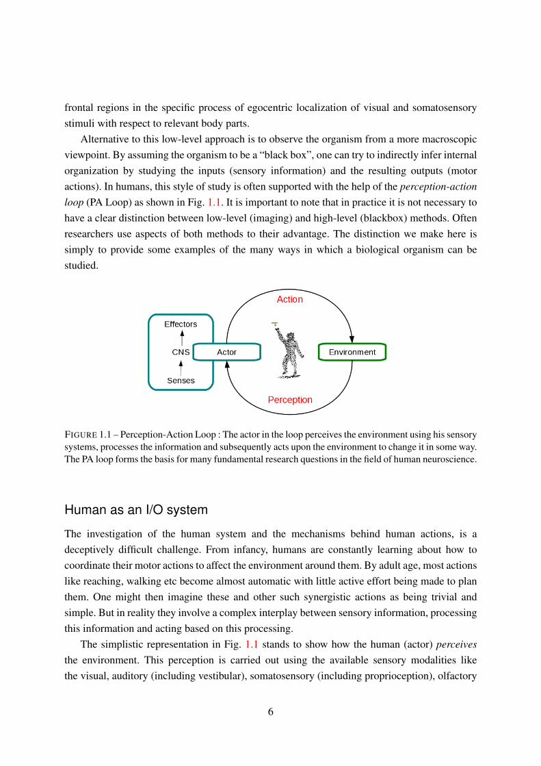
loop (PA Loop) as shown in Fig. 1.1. It is important to note that in practice it is not necessary to
have a clear distinction between low-level (imaging) and high-level (blackbox) methods. Often
researchers use aspects of both methods to their advantage. The distinction we make here is
simply to provide some examples of the many ways in which a biological organism can be
studied.
FIGURE 1.1 – Perception-Action Loop : The actor in the loop perceives the environment using his sensory
systems, processes the information and subsequently acts upon the environment to change it in some way.
The PA loop forms the basis for many fundamental research questions in the field of human neuroscience.
Human as an I/O system
The investigation of the human system and the mechanisms behind human actions, is a
deceptively difficult challenge. From infancy, humans are constantly learning about how to
coordinate their motor actions to affect the environment around them. By adult age, most actions
like reaching, walking etc become almost automatic with little active effort being made to plan
them. One might then imagine these and other such synergistic actions as being trivial and
simple. But in reality they involve a complex interplay between sensory information, processing
this information and acting based on this processing.
The simplistic representation in Fig. 1.1 stands to show how the human (actor) perceives
the environment. This perception is carried out using the available sensory modalities like
the visual, auditory (including vestibular), somatosensory (including proprioception), olfactory
6

Chapter 1 · Introduction · § 1.2
(smell) and gustatory (taste) systems. Each of these sensory systems provide the human Central
Nervous System (CNS) with some feedback of the current state of the environment. The role of
the CNS is to robustly combine these signals in a meaningful way that best serves the current
task at hand. Sensory integration refers to the process by which these signals are combined
in a meaningful fashion (see for example [Ernst and Bulthoff 2004]). Based on this combined
percept, the brain decides on a suitable action to execute on the environment via the body
effectors.
Due to the complexity of these processes, trying to understand them separately is not an
easy task. In order to simplify things, neuroscientists often try to isolate specific perception-
action effects by suppressing other sensory modalities, and/or, modifying the environment. For
example, we know that vision is vital to execute motor tasks like locomotion. However, humans
can still walk when vision is not available or severely impaired. Thus the mechanism of sensory
integration is robust enough to rely on other sources of information, like the vestibular system,
to compensate for missing senses. An earlier study investigated this by intentionally degrading
visual information and then observing the change in the motor action [Souman et al. 2009].
One interesting result from this particular study was that humans were found to walk in circles
when blindfolded, and even when walking with vision but in a featureless environment like
a desert. From this it was concluded that in the absence of a reliable directional reference,
veering from a straight course suggests to be a result of accumulating noise in the sensorimotor
system, rather than due to general biomechanical asymmetries. As alternative examples, study
of sensory integration could also be across the vision and haptic senses [Hayward 2009], vision
and audition [Hartcher-O’Brien et al. 2010], or, vision and proprioception [Haith et al. 2008] etc.
In the study by [Bennequin et al. 2009], it was shown that the kinematic and temporal features
of human movements during drawing and locomotion are well accounted for, by considering
their representation in three geometries, Euclidian, equi-affine and full affine. The results from
this study propose the possibility that the brain uses different mixtures of these geometries to
encode movement duration and speed, and the ontogeny of such representations.
In general the study of sensory perception and motor action can be aggregated under the
term sensorimotor integration. The examples presented in this section are only a few among
many studies that use this style to infer knowledge about the human system. A more expansive
reading of methods in the study of humans can be found in [McGuigan 1996], with a general
overview of the ideas in neuroscience in the books by [Gescheider 1997], [Bear et al. 2006] and
[Berthoz 2009].
Representing average human movements
Within the context of this thesis the idea to understand human action as a function of perception
is interesting, as are the methods used to make these inferences. In particular we are interested in
7

FIGURE 1.2 – Bio-mimesis and bio-inspiration in robotics, towards human-like and human-do-like
machines From left to right, Robotuna II the robotic fish from MIT [Beal and Sachinis ], Salamandar
robot from EPFL [Ijspeert et al. 2005], Aibo the robotic dog from Sony [SonyCorp ], Big Dog from
Boston Dynamics [Raibert 2008], Lucy of Vrije Unversiteit Brussel [Vanderborght et al. 2008] and HRP-
2, the humanoid robot from Kawada Industries [Kaneko et al. 2004]. The striking similarity between a
human and the humanoid robot’s structure sometimes leads people to expect it to be capable of other
anthropomorphic abilities well beyond its limits and intelligence... like for example riding a motorbike !
how we can represent average human behavior by testing a small subset of humans in controlled
conditons, and then qualify the observed results using statistical tests. To make this point more
clear, we can consider any number of studies in neuroscience. For example, head and body
movements during locomotion have been shown to be closely linked to perceiving the future
walking environment [Grasso et al. 1998; Patla et al. 1999; Hollands et al. 2001; Imai et al.
2001; Courtine and Schieppati 2003; Hicheur et al. 2005]. In the study of [Sreenivasa et al.
2008], the goal was to investigate the relationship between the head and trunk during walking
and turning. To do this, the behavior of several participants was recorded while modulating
the task slightly (changing the turning angle). The resulting head and trunk behavior was then
analyzed and certain stereotypical results were extracted. This stereotypy was proven to be
statistically significant. The resulting inference based on this stereotypy can then, and only
then, be said to represent average human behavior for that particular experimental scenario.
Such a methodology is of course not limited to joint angles during locomotion, but to any
parameter extracted from human data. For example, in [Hicheur et al. 2007] and [Souman et al.
2009] similar methods were applied to human locomotion trajectories. In neuroscience, such
methodology is the accepted norm and followed by most, if not all, of the human studies that are
referred to in this thesis. For these reasons, we employ similar methods in this thesis to study,
quantify and subsequently qualify our models of human movements before applying them to
humanoid robots.
8

Chapter 1 · Introduction · § 1.3
1.3 Anthropomorphism and biological principles in robotics
The premise of this thesis lies in the transfer of ideas from the movement of humans to that
of human-like machines. We now momentarily shift our focus away from human movements,
and towards human-like and other biologically inspired machines and principles in robotics.
Legged locomotion in nature has always been of much interest to roboticists and engineers (but
see also [Hayward 1993]). There is a long list of machines that can walk, crawl or otherwise
locomote using legs. Some examples of multi-ped robots are shown in Fig. 1.2. The versatile
amphibious robot Salamandra robotica is modeled after the salamander. In addition to being
physically similar to its natural counterpart, the motion of the robot’s spinal cord is modeled
using biological principles of neural oscillators. There are numerous further examples of such
robots that are “bio-inspired”. A popular four legged robot is the Big Dog by Boston Dynamics.
Many more such examples can be found in today’s robots, the robotic fish, bird, dog, snake etc
were all built to mimic nature’s blueprint and often use established biological principles to plan
their motions. In this regard, modern humanoid robots are the latest in a long line of such robots
that were inspired from nature.
In robotics literature we sometimes find the distinction between bio-inspired and bio-
mimetic approaches. In the former, the goal is to reproduce observations from biology but
not necessarily the underlying means. By bio-mimetic robots, we aim to classify robots that
reproduce both the phenomenon and the means. However, in practice most approaches lie
somewhere between these two notional classifications (see Chapter 60 in the book by [Siciliano
and Khatib 2008] for a more detailed debate). For the purpose of this thesis, we suggest a
similar parallel between motion imitation and motion modeling, with imitation being closer
to bio-inspired and modeling closer to bio-mimesis. In the following we concentrate on bio-
inspired and bio-mimetic approaches as applied to the motion of humanoid or semi-humanoid
robots.
Automatons
An automaton is a machine built to execute a predefined set of movements without any
perception of its environment. Thus, in this sense an automaton is not a robot. But this is not
the same as saying that they are simple machines. The history of automatons can be traced
back a long time and often they were complex mechanisms with fine construction. A popular
early automaton is the warrior automaton designed by Leonardo da Vinci in 1495. Da vinci
was of firm belief that understanding the human anatomy was vital to reproduce it accurately
in paintings or machines. Nevertheless, automatons can be seen as more a measure of their
creator’s caliber and skill, rather than scientific acumen. This brings automatons closer to art
than science. Some examples of anthropomorphic automatons are shown in Fig. 1.3. Even today
9

FIGURE 1.3 – Early automatons : Mechanical constructions given “life” by human ingenuity. Arguably,
automatons lie somewhere between the fields of art, engineering and science. Pictures from : Musee de
l’automate de Souillac, Souillac, France
automatons find application in the entertainment industry like theme parks and museums.
Motion imitation
The easiest way to make a humanoid robot behave like a human, is to simply copy a human’s
movements. The connoted simplicity is with regard to the amount we need to understand the
human movements in order to reproduce them. Note that here we are suggesting a qualitative
difference between this kind of imitation and the implied “imitation” of an automaton. Even
without requiring to understand human movements, motion imitation for a humanoid robot is
more than just a straightforward transfer. The challenges here arise due to the kinematic and
dynamic disparity between the human and the humanoid.
Like a human, a humanoid robot has two hands, two legs, a torso, a head etc. While the
overall similarity can be quite convincing at first glance, the organization of how each joint
moves with respect to the other, and by how much, is very different. Additionally, the number
of Degrees of Freedom (DoFs) available to a human exceed even the most technologically
advanced humanoids. This kinematic disparity is magnified by the fact that humans are never
constructed in standard shapes and sizes. Thus, any imitation framework has to first be
intelligent enough to appropriately scale human motion and then map this motion onto the
appropriate robot joints.
The second problem is that of dynamics. Agility in humans is not only the ability to move
fast, but doing so while maintaining dynamic balance at the same time. Walking and running
10

Chapter 1 · Introduction · § 1.3
FIGURE 1.4 – Human to humanoid robot motion imitation : Pictures on the left are a preview from a
study described later in this thesis. In scenarios with low dynamics, a humanoid robot can be made to
imitate human motion or human behavior. On the right is an illustration of a tightrope walker : Requiring
fine balance and quick reflexes, tight rope walking is an example of a benchmark for highly dynamic
human movements. How would one go about imitating this behavior on a humanoid ?
are examples of dynamic movements, but humans are capable of a lot more. An example of this
is the tightrope walker’s trick popular in many cultures (Fig. 1.4). The idea here is to walk on a
tensioned wire suspended over two points. By placing one leg in front of the other the support
base in the lateral plane is drastically reduced. Hence, the walker sways rapidly from side to
side to maintain balance on an oscillating rope. While it may be possible to design motors that
can mimic the speed of such motion, or even faster, the mechanisms behind maintaining fast
reactive balance are not well understood. In the case of humanoid robots, often the dynamics of
the system is simplified for various reasons (this is further elaborated in §2.3). A consequence
of the relative mechanical and computational simplicity is that the humanoids of today are
well behind human capabilities in terms of agility and dynamics. This brings us back to the
problem of imitating human movements which are possibly beyond the dynamic capabilities of
the humanoid.
Several studies have tried to solve these issues in motion imitation using a variety of
approaches. For example, in the study of [Nakaoka et al. 2005] the humanoid robot HRP-
2 imitated the complicated Japanese dance of Aizu-Bandaisan. Since the original dancing
movements were outside the dynamic limits of the robot, the movements themselves were
modified such that they conformed to the robot’s limitations while still being close to the
original template. Another example of modification of movements for dynamic and kinematic
conformity is the study by [Suleiman et al. 2008]. Here the recorded motion was that of a boxer
and well outside the robot’s limits. Using an optimization approach the authors successfully
reproduced the motion on HRP-2. Real-time imitation adds additional level of challenges and
11

were tackled in the studies by [Dariush et al. 2008] & [Yamane and Hodgins 2009]. In §3.2 we
present a short overview of an alternative method for real-time imitation of human movements
by a humanoid robot. Further literature and references on motion imitation can be found in the
thesis by [Montecillo-Puente 2010].
Motion modeling
Under the umbrella term of “motion modeling”, we gather together methods that try to
understand the principles behind the motion by suitably representing them, and then consequently
modifying them for the purpose of driving humanoid motion. Here we also include methods
where feedback from the environment is used to learn the appropriate actions. This is of course
a very broad classification and encompasses many sub-categories of research methodologies.
The reason for grouping them together in such a manner is that the methods described here
come closest to those researched in this thesis. Here we give some examples of such studies in
robotics research.
In a humanoid robot, low-level control is effected by modulating the joint angles or joint
torques. Corresponding to this, researchers often use movement primitives to encode human
movements. Movement primitives can be used to represent the co-activation of joints as
temporal functions (see [Schaal et al. 2004] for an overview). Usually, a finite set of movement
primitives appropriately weighted then encode a large range of movements. From a robotics
point of view, expressing the motion of redundant anthropomorphic systems using a reduced
representation is interesting. This representation is close to the biological theory of motor
control that suggests that the primate CNS also generates movements using a finite set of
elementary motor components. Movement primitives have found extensive use in robotics like
in the balance control of a humanoid [Hauser et al. 2007], robotic arm movements [Lim et al.
2005], as well as in statistical learning frameworks [Mussa-Ivaldi and Bizzi 2000; Todorov and
Ghahramani 2003; Bitzer and Vijayakumar 2009].
Human movements have been suggested to be optimal in terms of metrics like jerk [Flash
and Hogan 1985], torque change [Uno et al. 1989], variance [Harris and Wolpert 1998],
effort and error [Todorov and Jordan 2002] or energy of motor neurons [Guigon et al. 2007].
This is often reflected in the mathematical models that aim to model and reproduce these
movements (see [Todorov and Jordan 2004] for an overview and [Laschi et al. 2006] for one
such application in robotics). Optimal control is the problem of finding a control law for a
system such that some optimality criterion is satisfied. In robotics, this usually means finding
a function describing the evolution of the control variable that moves the robot from an initial
to a final configuration (by obeying a differential equation), such that a related cost function
is minimized. For example, [Mitrovic et al. 2010] studied target reaching tasks for redundant
anthropomorphic manipulators. The key qualification of the motion was the underlying premise
12

Chapter 1 · Introduction · § 1.3
of minimal energy consumption and compliance. When looking at locomotion, it has been
shown that numerical optimization techniques can be efficiently used to create self-stable
running motions for a human-like robot model [Mombaur 2008]. A similar optimal framework
was also applied to explain stereotypy in human locomotion trajectories, and subsequently
applied on a humanoid robot [Mombaur et al. 2010].
An alternative method to incorporate human movement information in the motion of
humanoid robots is the study by [Harada et al. 2009]. Here, human walking motion was
parametrized by extracting information like step length, waist height etc. This information was
then applied to the motion of a humanoid robot, to make it look more human-like. Similarly,
other kinematic characteristics of human movements like, speed and rotational angle of turns,
were used to generate realistic humanoid walking and turning motions [Miura et al. 2009]. In
[Miura et al. 2008], the authors showed how the foot slip during a human twirling movement,
can be used to perform similar twirls on a humanoid robot.
Other notable approaches are those put forward by proponents of the biological “mimesis
theory” in robotics. For example, the bio-mimetic approaches in [Lee and Nakamura 2007] and
[Ott et al. 2008]. In the former study, the authors propose a method that recognizes the pose
of a demonstrator using a Hidden Markov Models (HMMs) based mimesis scheme. Here, the
recognition was achieved using the robot’s monocular vision. A similar HMM based approach
was used in [Ott et al. 2008], but this time with the use of motion capture technology (see
§3.1.1). The authors implemented a Cartesian control scheme to drive humanoid motion from
recorded human movements, via virtual springs. The application in both these studies was closer
to imitation than modeling. Nevertheless, we note that the mimesis model using HMMs is a
promising way to model and classify human movements.
In order to model human movement it is not always necessary to work at the joint level.
Behavior-based robotics is the term popularly used to refer to approaches that characterize
behaviors rather than movements. This can be done, for example, by developing semantics
to categorize complex human motions. In [Inamura et al. 2004], the authors explore the
mimesis theory in biology which concerns behavioral imitation in humans, from a robotics
perspective. Using Hidden Markov Models (HMMs) they propose a mathematical model that
integrates symbol emergence, behavior recognition, self-behavior generation and acquiring of
motion primitives. A later study by [Takano et al. 2007] used a combination of representative
symbols (from human movements) to generate a derived behavior for a humanoid robot. Other
approaches aim at modeling human-like behaviors for the purpose of human-robot social
interactions [Thomaz and Breazeal 2010]. While such behavior based methods are not directly
related to human or humanoid movements, it can be appreciated that often the correct human-
like movement for a humanoid robot, might come for the most appropriate behavioral response.
The use of human knowledge for the control of humanoid robots is a relatively recent
development. Despite that, there are various approaches and methods already being studied
13

and implemented by roboticists. It can already be seen that the synergy between robotics and
neuroscience can be advantageous to both fields (see [Dario et al. 2003] for a review of neuro-
engineering and neuro-robotics). The purpose of this section was not to provide an exhaustive
literature review, but rather to provide an introduction to some of these ideas. There are many
methods and extensions to the examples cited here and some of these are further elaborated and
referred to later on in this thesis.
1.4 Motivation & Contribution
The motivation behind this thesis was already covered to a large extent in §1.1, where we
established why the study of human movements is relevant to humanoid robotics. As humanoid
robots become progressively complex so do the algorithms being used to generate their motion.
Applied methods like local optimization are a quick way to solve for motion of a multiple
degrees of freedom robot. However, due to the redundant nature of the humanoid robot, the
result might not correspond to the best or most human-like solution. We have already underlined
why it is vital for humanoids to behave in a human-like manner. Hence the motivation behind
this work is to model human movements to guide conventional robotics algorithms towards
more human-like solutions. At the same time we also hope to understand more about human
movements themselves.
The general contribution of this thesis is in bringing to the robotics community, a systematic
and rigorous way of applying knowledge from the study of humans. In the scenarios described in
this thesis, we profit from experimental methodologies from the field of human neuroscience.
The models developed within this thesis are then used to drive humanoid robot motion. To
effect this transfer we use established state-of-the-art approaches on dynamic balance, task-
based redundancy resolution, and stepping motion generation for humanoid robots.
We can develop three contributions arising from this thesis :
• Formal definition and synthesis of human movements such that they can be applied to
the control of humanoid robots. For example, in Chapter 4, these were used to implement
yoyo-playing on the humanoid robot.
• Application of neuroscience principles on the role of the head in human locomotion,
within a humanoid robotics perspective to generate deliberative whole-body motion
including stepping.
• A novel approach to generate goal-driven walking for humanoid robots. The organization
of similar movements in humans was modeled, such that they could be generalized to
other anthropomorphic characters like humanoid robots.
14

Chapter 1 · Introduction · § 1.6
1.5 Chapter organization
In the present Chapter we introduced some important concepts in the study of human
movements and in the field of humanoid robotics. We also outlined the motivation behind the
work conducted in this thesis, and its main contributions. Chapter 2 serves the purpose of giving
an overview of task-based prioritized inverse kinematics and ZMP-based humanoid stepping
approaches. These state of the art approaches in humanoid motion planning are recurring themes
in this thesis, and vital to the application of the models that were developed.
Part I of this thesis, divided into two chapters, deals with making the transition from motion
imitation to motion modeling.
In Chapter 3 we introduce the motion capture technology which is used as the basis for
human motion recording in this thesis. We also introduce the humanoid robot HRP-2, which
acts as the platform for showcasing the results of our work. The chapter then reviews two studies
that were related to the general themes in this thesis, but do not form its main contributions. The
first part §3.2 relates to online motion imitation between a human actor and the humanoid robot
HRP-2. The next part (§3.3) reviews an approach to use human movement primitives to generate
humanoid arm reaching motions. Both these studies were a result of collaborative work.
To address the issue of dynamic control in arm movements, Chapter 4 models the repetitive
movements during yoyo-playing. First, we look at human yoyo playing to better understand
how humans manipulate a yoyo to generate stable oscillations. The knowledge gained from
human movements is then used to generate stable yoyo playing motion for the humanoid robot
HRP-2.
Part II builds on the notion of motion modeling and shifts focus towards locomotion in
humans and humanoids.
Chapter 5 looks at whole-body motions and the role played by the head during locomotion.
By taking inspiration from the field of human neuroscience, we develop a control algorithm
to generate deliberative head-driven motion, including stepping, for a humanoid robot. Here,
the perception of the humanoid is augmented by introducing the human into the humanoid’s
perception-action loop.
The principle illustrated in Chapter 5 is extended in Chapter 6 to generate goal-driven
locomotion for humanoids. We study human motion during a goal-driven walking and grasping
task, and extract movement invariants that are characterized as rules. The knowledge from
human movements are then transferred to the humanoid robot, to generate smooth and realistic
motion.
We conclude this thesis in Chapter 7 where we discuss the results of this work, and the
implications of biological motivation in the field of humanoid robotics.
15

1.6 Related publications
The following publications form the basis of this thesis :
– Sreenivasa MN, Soueres P & Laumond JP : On using human movement invariants to
generate target-driven anthropomorphic locomotion. IEEE Int. Conf. Biomedical Robotics
and Bio- mechatronics (BioRob) 2010
– Sreenivasa MN, Soueres P, Laumond JP & Berthoz A : Steering a humanoid robot by its
head. IEEE Int. Conf. Intelligent Robots and Systems (IROS) 2009
– Mombaur K & Sreenivasa MN : HRP-2 plays the yoyo : From human to humanoid yoyo
playing using optimal control. IEEE Int. Conf. Robotics and Automation (ICRA) 2010
– Mombaur K & Sreenivasa MN : Inverse optimal control as a tool to understand human
yoyo playing. 8th Int. Conf. Numerical Analysis and Applied Mathematics (ICNAAM)
2010
– Montecillo-Puente FJ, Sreenivasa MN & Laumond JP : On Real-Time Whole-Body
Human-Humanoid Motion Transfer. Int. Conf. Informatics in Control, Automation and
Robotics (ICINCO) 2010
– Tuan TM, Soueres P, Taix M, Sreenivasa MN & Halgand C : Humanoid human-like
reaching control based on movement primitives. IEEE Int. Symp. on Robot and Human
Interactive Communication (Ro-Man) 2010
The work presented in this thesis follows from previous research on human locomotion which
was conducted outside of the thesis, but is directly related to it. The following publications are
related to the runup to the work in this thesis (research conducted at the Max Planck Institute
for Biological Cybernetics, Tubingen, Germany) :
– Sreenivasa MN, Frissen I, Souman JL & Ernst MO : Walking along curved paths of
different angles : the relationship between head and trunk turning. Experimental Brain
Research 2008
– Sreenivasa MN, Frissen I, Souman JL & Ernst MO : Walking in natural environments.
Gait & Posture 2010 (Under review)
– Souman JL, Frissen I, Sreenivasa MN & Ernst MO : Walking straight into circles. Current
Biology 2009
Abstracts
– Souman JL, Frissen I, Sreenivasa MN & Ernst MO : Walking in circles : the role of visual
information in navigation. 31st European Conference on Visual Perception (ECVP) 2008
– Sreenivasa MN, Frissen I, Souman JL & Ernst MO : Head-trunk relation before and
during a turn : the effect of turn angle. 10th Tubingen Perception Conference (TWK)
2007
– Sreenivasa MN, Frissen I, Souman JL & Ernst MO : Measuring Natural Walking using
16

Chapter 1 · Introduction · § 1.6
GPS and IMU Technologies. CyberWalk Workshop 2008, Tubingen, Germany
17


2Generation of humanoid robot motion
THE basis of this thesis can be divided into two fields “Modeling of human movements” and
“Generation of humanoid robot motion”. The main contributions of this work are in the
former, and in transferring those ideas and results to the latter. The results developed within
this thesis would not have been possible without the supporting research in motion planning
for humanoid robots. In order to understand the niche where this thesis fits, we have to first
understand how we can generate motion for a humanoid robot. This builds on decades of work in
mechanics, mathematics and robotics, and it would not be possible to provide a comprehensive
review of all methods and principles, or even those particular to this thesis. Instead, this Chapter
provides an overview of certain aspects of motion generation that are important within the
context of our present work. Additionally, each topic is supported by extensive and authoritative
references for further reading.
A humanoid robot is an under-actuated and redundant system. Under-actuation is a property
of a system where the number of driving actuators are less than the number of Degrees of
Freedom (DoFs). In the particular case of a humanoid robot, this refers to the fact that the robot
has a “free-flying root” and that the motion of this root joint is indirectly actuated using its other
DoFs (for example by bipedal gait). Redundancy, in the context of manipulator kinematics, is
always with respect to performing some function. If the manipulator has more DoFs than those
required to control a desired variable, then it is said to be redundant. The question here is, what
to do with the remaining DoFs ?
19

FIGURE 2.1 – A simple 2D kinematic chain consisting of 3 rigid links connected by revolute joints. The
point G represents the goal towards which point C, attached to link A3, should converge.
In the following sections we review the methods and principles developed to generate
humanoid robot motion. But first, we start by the basic definitions and problems in kinematics.
2.1 The kinematic chain
Within the context of robotics, kinematics is the study of the motion of bodies in a mechanism,
without taking into account the forces/torques that cause that motion. In order to plan and
control these motions, it is first important to appropriately represent the pose of a body.
We start with Fig. 2.1, where we show the idealized illustration of a three-link manipulator.
We assume that the links A1, A2, A3 are rigid bodies. Each link is connected by a joint that
constrains their relative motion. An additional assumption is that the joints have ideal contact
with no clearance. The way the relative motion is constrained depends on the type of joint. For
the revolute joints in Fig. 2.1, each link is constrained to rotate only about one axis, relative to
its adjoining link, i.e. each joint creates a 1DoF linkage. Link A1 is fixed at the point O via a
revolute joint, thus the overall system has 3DoF. The length of each link is denoted by li, and its
relative angle with respect to the previous link as qi.
Forward kinematics can be defined as the problem of finding the position of the end effector
(C). To do this we can use the known geometric properties to calculate,
−→OC =
[
xC
yC
]
=
[
l1cos(q1)+ l2cos(q1 +q2)+ l3cos(q1 +q2 +q3)
l1sin(q1)+ l2sin(q1 +q2)+ l3sin(q1 +q2 +q3)
]
(2.1)
In (2.1), (q1,q2,q3) are called the joint configurations of the kinematic chain.
20

Chapter 2 · Generation of humanoid robot motion · § 2.2
2.2 Inverse kinematics
The opposite of the problem in (2.1), is to calculate the joint configurations qi such that the
end effector tracks a given target. For example, in the case above we could wish to move the
end-effector C to the desired position G. The process of finding the configuration q to place an
end-effector at a desired position and orientation is called the inverse kinematics problem.
q = x−1(s) (2.2)
where, s = x(q) defines a task. In the example Fig. 2.1, a task could be to minimize the distance
between C and G. Thus,
x(q) =
(
xC − xG
yC − yG
)
−→ 0 (2.3)
Note that in the above formulation, the task was specified in 2 dimensional space (x and y
positions) while the system in Fig. 2.1 has 3 degrees of freedom. If x(q) = 0 is solvable, then
there may exist more than one configuration q that solves this task. This illustrates the issue of
redundancy, where the dimension of the task is smaller than the available DoF.
We can generalize the above example to a kinematic chain with n DoF, and configuration
q = (q1,q2, ....,qn) ∈ Rn. For this general case,
x(q) = 0 (2.4)
can be any m dimensional vector function (often non-linear) that defines some kinematic
properties.
If for a configuration q, the equation (2.4) is satisfied and to be preserved, we call it a
constraint. If (2.4) is not yet satisfied then it is called a task. If the dimension of the task m
exceeds the degrees of freedom n, then the system has no solution. In the opposite case (m < n),
the inverse as in (2.2) is not defined. We can use numerical methods to solve this problem.
2.2.1 Differential kinematics
In order to solve the system (2.4), we can compute small configuration updates towards
completing the task. The iterative process of mapping small changes in the joint space to the
task space via a differential relation is known as differential kinematics [Nakamura 1991]. Here,
we assume (2.4) to be differentiable functions with respect to the joint configuration.
The jacobian of the task forms this differentiable relation, and the configuration updates that
regulate the error to 0 can be calculated from the linear differential equation ([Liegeois 1977]),
21

Jq = x (2.5)
where, J = J(q) is the m× n jacobian matrix computed as J = ∂x∂q(q). The solution to (2.5)
depends on the condition of the jacobian matrix J. If m = n and |J| 6= 0, then we can simply
invert the matrix J and calculate the joint variations as q = J−1x. If m > n, then there may not
be any solutions.
If m < n and J is non-singular, (2.5) can be inverted to give a solution,
q = J+x = JT (JJT )−1x
where, J+ is the pseudo-inverse of J [Boullion and Odell 1971]. The general solution of the
system can be written as,
q = J+x+(I − J+J)z (2.6)
where, (I−J+J) is the projector on the null-space of J, and z is a n-dimensional arbitrary vector.
The first term on the right side of (2.6) is the minimal-norm solution and z in the second term
can be used to span the whole affine subspace of solutions.
In the case that J is singular the differential update process will lead to large undesirable
configuration updates in the neighborhood of the singularity. Singularity occurs, when the task
function has a local minima whose neighborhood does not intersect x(q) = 0. At such a minima
the product JJT becomes ill-conditioned and the results diverge. To avoid this divergence we
can employ methods like that proposed in [Nakamura and Hanafusa 1986]. For the sake of the
overview we do not develop these singularity-avoidance methods further, but direct the reader
to the references cited.
2.2.2 Multiple tasks and prioritization
A powerful capability of a redundant kinematic system like a humanoid robot, is to complete
multiple tasks simultaneously. In (2.6) the vector z can be used to define additional tasks and
constraints without disturbing the solution of the previous task. However, solving for multiple
tasks could in some situations lead to conflicts which result in neither of the tasks being satisfied.
This problem can be solved by assigning priorities to each of the tasks and then solving this
prioritized stack [Siciliano and Slotine 1991].
We illustrate this with an example scenario for the humanoid robot HRP-2 as shown in Fig.
2.2. For the sake of explanation we assume the robot’s feet are fixed. In the picture on the left
we define two tasks, the first is to reach a target with the right hand. We call this Task 1 denoted
by x1(q). The second task is to look at the target, let us call this xgaze(q). For these two tasks,
22

Chapter 2 · Generation of humanoid robot motion · § 2.2
FIGURE 2.2 – Defining multiple tasks for a humanoid robot : Picture of left shows HRP-2 completing
two tasks, reach the red target with the right hand and looking at it. On the right we add an additional
reaching task for the left hand. In order to avoid conflicts we have to enforce task prioritization.
the structure of HRP-2 is redundant and both tasks can be solved without conflicts. In the right
picture, we modify xgaze(q) to look at a new target. We add a second task, Task 2 (x2(q)), which
is to reach this new target with the left hand.
The second target associated to x2(q) is slightly out of reach, and solving for this might
conflict with the solution of the first task, x1(q). Note that the gaze task in both situations can
be solved since this does not affect the other task solutions. In order to find a resolution we can
assign a higher priority to task 1 over task 2. To simplify the explanation we ignore the gaze
tasks for the time being. The solutions for task 1, as follows from (2.6), can be written as,
q = J+1 x1 +(I − J+1 J1)z q,z ∈ Rn (2.7)
Replacing q in the above equation, with the similar expression for task 2, we get,
x2 − J2J+1 x1 = J2(I − J+1 J1)z (2.8)
Denoting P1△
= (I − J+1 J1) and q1△
= J+1 x2, [Nakamura 1991] showed that the solution of the
system in (2.8) can be solved to,
q = J+1 x1 +(J2P1)+(x2 − J2q1) (2.9)
In order to deal with multiple tasks, the generic iterative expressions for solving k tasks with
descending order of priority are (as per [Siciliano and Slotine 1991]),
23

FIGURE 2.3 – The change in shape of the support polygon of a humanoid robot as it steps. For the static
case and for quasi-static motions the projection of the CoM (green ball) should remain inside this support
polygon.
P0 = I
Ji = JiPi−1
Pi = I − J+i Ji
qi+1 = J+i+1(xi+1 − Ji+1qi)
where, i goes from 1 to k, Pi is the projector associated with the ith task, Ji is the jacobian of the
ith task and I is the n×n identity matrix. The configuration update δqi is iteratively computed
for all tasks.
2.3 Dynamic balance of a humanoid robot
Planning stable bipedal motion for an anthropomorphic humanoid robot is a challenging task
from a mathematical and practical point of view and has received substantial attention from
research over the past decade. Often humanoids are built with large feet to provide a bigger
support area while standing. In robotic parlance, this support area is called the support polygon,
and its shape and size depend on the current configuration of the feet (for example see shaded
area in Fig. 2.3).
To explain the control of a humanoid robot during dynamic activities like locomotion, we
first develop the idea of the Zero Moment Point (ZMP) [Vukobratovic et al. 1990]. We present
here the derivation of the ZMP as reported in [Wieber 2002].
24

Chapter 2 · Generation of humanoid robot motion · § 2.3
Zero Moment Point (ZMP)
Consider a walking system with k rigid bodies of masses mk. The external forces acting on
this system are gravity and the forces at the contact points. In order to walk, the system has
to appropriately modify these contact forces, for example by repeatedly breaking contact and
regaining it.
The dynamic wrench of this system can be written as,
[
∑mkxk
∑xk ×mkxk +RkIkωk −Rk((Ikωk)×ωk)
]
(2.10)
where xk is the position of the Center of Mass (CoM) of the kth body, Rk is the relevant rotation
matrix, ωk its rotation speed, mk the mass and Ik the inertia matrix.
The basic laws of mechanics state that the dynamic wrench of an object is strictly equal to
the total wrench of the exterior forces acting on it. If the dynamic wrench is 0, the system is
static and the total wrench of gravity and contact forces is 0.
For the particular case that all contact points are on a horizontal plane,
−∑mkgn+∑ fkn = 0
−∑xk ×mkgn+∑ pk × fkn = 0
where, n is a vertical unit vector, pk is the position of the kth contact point and fk the vertical
contact force.
When the above system is moving, we have to consider the dynamic wrench as in (2.10)
giving,
−∑mkgn+∑ fkn = (T.n)n
−∑xk ×mkgn+∑ pk × fkn = n×R×n
where, T and R are the derivatives of linear and angular momentum as in (2.10). This can be
rewritten as,
mgxG ×n+n×R×n
mg+T.n=
∑ fk pk ×n
∑ fk
(2.11)
where, m = ∑mk is the total mass of the system and xG = ∑mkxk
mis the position of the center of
gravity.
The point expressed in (2.11) is called the Zero Moment Point (ZMP). In simpler terms, the
ZMP of a rigid body system is defined as the point where its horizontal angular momentum is
25

FIGURE 2.4 – Cart-table model : The complicated exact dynamics of a humanoid robot is replaced by a
simplified cart-table model. The red point inside the foot of the table represents the momentary ZMP of
the system.
zero [Vukobratovic et al. 1990]. In the field of neuroscience and human psychophysics we find
the equivalent term of Center of Pressure (CoP).
Simplified dynamic model of a humanoid
Using the ZMP formulation to control a complex distributed mass system like a humanoid robot
is a problematic task for two reasons. First, from a control point of view the computation of the
ZMP should be instantaneous to allow time to react to an unfavorable state. Second, once such
a state has been detected the system has to be modified to bring it back into the stability space.
Computing a feedback law that does this for the complete dynamic model of the humanoid is a
difficult and computationally expensive task.
In 2003 [Kajita et al. 2003], proposed a simplified model where the bipedal structure of
a humanoid is approximated as a wheeled cart moving on top of a massless table. Fig. 2.4
illustrates this model. The foot of the table corresponds to the support polygon of the robot and
the cart represents the center of gravity of the robot. According to [Vukobratovic et al. 1990]
the distribution of the reaction force of the ground can be replaced by an equivalent reaction
force R exerted on the ZMP.
In the cart-table model, the cart has to accelerate to keep the table upright. The ZMP has to
exist inside the table foot and the moment around it must be zero. Using this property of zero
momentum, the x-y position of the ZMP can be calculated as,
[
px
py
]
=
[
x− zc
gx
y− zc
gy
]
(2.12)
26

Chapter 2 · Generation of humanoid robot motion · § 2.3
FIGURE 2.5 – Left : Illustration of the projection of CoM (red) and the ZMP (black) of an articulated
walking system. Right : Plot of the x and y position of the CoM and ZMP. The motion in x-y plane is
shown in 2.6. Note that both figures are for illustration and not to scale.
where, px, py are the x and y positions of the ZMP, respectively, and zc is the height of the CoM
of the cart. The equation in (2.12) gives us the relationship between the ZMP and the position
and acceleration of the CoM. The problem now is to manipulate the ZMP such that it stays
within the support polygon and preferably away from its edges.
Optimal control of ZMP
In order to plan a valid ZMP trajectory we can control its position via the CoM using the relation
in (2.12). To perform the inversion of (2.12), [Kajita et al. 2003] proposed the use of an optimal
linear-quadratic control with an infinite preview horizon.
The control variable in Kajita’s method was the third derivative of the CoM position. For
instance, in the sagittal plane this is ux =...x , with the restricted state representation of the system
given by,
X =
0 1 0
0 0 1
0 0 0
X +
0
0
1
ux (2.13)
with the output equation,
px =[
1 0 − zc
g
]
X (2.14)
where, X = [ x x x ]T is the state vector, x being the abscissa of the CoM. The same analysis is
conducted for the y-dimension to derive the control uy.
This continuous-time formulation is then discretized and solved by specifying a quadratic
27

cost function to be minimized. The cost function defines the optimized minimum of a weighted
sum of three terms. The first term is the error of the ZMP with respect to its reference. The
second term is the variation in the state of the CoM, and the third term is the variation of the
control. The optimality criteria is further detailed in Annex 7, and the full definition can be
found in [Kajita et al. 2003].
Fig. 2.5 illustrates the motion of the planned ZMP and corresponding motion of the
projection of the robot CoM. As the robot switches from double to single support phase, the
ZMP is shifted to the current support foot in a piecewise linear manner (black lines). Using the
system description outlined above, the idea is to generate a smooth oscillating trajectory for the
CoM (red line). The motions of the CoM and ZMP with relation to the robot’s feet is made
more clear in Fig. 2.6.
FIGURE 2.6 – Dynamic stepping motion for 4 consecutive steps : First a piece-wise linear ZMP path is
planned within the support polygons (solid black line). In the beginning the ZMP is at a point between
the feet (green circles). During single support the ZMP is fixed at the support foot (brown squares), and
then moved between the feet after the stepping foot has landed. For dynamic stepping, the motion of
the CoM is calculated by an optimal controller (smooth red line) and oscillates between the ZMP path.
Adapted from [Kanoun 2009].
2.4 Implementation and software
The inverse kinematics framework in §2.2 and ZMP based methods in §2.3 together form
powerful tools to exploit the manipulability and locomotive skills of humanoid robots. The
merger of these tools was one of the contributions of the work in [Kanoun 2009]. The software
developed as a result of this research is called GIK, which stands for Generalized Inverse
Kinematics. This thesis uses GIK as a basis for the generation of humanoid robot motion.
The general idea behind GIK is to give the highest priority to the tasks required for dynamic
walking. This is necessary as the humanoid should never be allowed to lose balance and fall. To
implement dynamic walking [Kanoun 2009] defined two tasks,
28

Chapter 2 · Generation of humanoid robot motion · § 2.4
FIGURE 2.7 – Organization of software for generating, testing and executing humanoid robot motion.
Communication between distributed user modules was acheived under the GenoM architecture.
• The first dynamic walking task is to control the position of the humanoid CoM. The
reference for this task comes from the optimal controller defined in §2.3.
• The second dynamic walking task is to control the position and orientation of the stepping
foot and is varied depending on the walk phase (double or single support). The actual
motion of the stepping foot is planned using the minimum-jerk criteria as defined by
[Shadmehr and Wise 2005].
All other tasks follow these two tasks in priority level, and allow planning of a wide range of
manipulation and locomotion activities, like the experiments conducted in this thesis.
The implementation of GIK enables the user to define equality tasks for body position,
orientation, parallelism and other geometric criteria. For example, in order to generate motion
for the first scenario shown in Fig. 2.2 we need to define two tasks. First, given a target position,
we define a Gaze task which orients HRP-2’s head towards the target. The right hand can be
made to reach the target by either defining a Position or Homogeneous Transformation task,
as necessary. Additionally, in order to ensure stability of the robot we can also define a CoM
constraint that maintains the center of mass in its present position (inside the support polygon).
The software allows the user to further define the start and end of each of these tasks.
Additional objects that can be added to this task stack pertain to dynamic locomotion. As
illustrated in Fig. 2.6, the locomotion objects consist of three elements, an initial ZMP shift
element, a foot motion element, and a final ZMP shift element. The duration of each of these
elements can be defined by the user, as well as the final position and orientation of the stepping
foot. By building a series of such locomotion elements, we can generate dynamic locomotion.
After defining a stack of tasks, possibly including locomotion objects, the software GIK
resolves the motion using a prioritized inverse kinematics solver built on top of an equality
29

system solver. The dynamic walk generation is based on the ZMP formulation, and integrated
within the software. The joints limits and resolution of singularities are also taken into account
during the solution stage. At this level of motion generation, the software does not guarantee
stability and this is left up to the user to implement by using an effective combination of tasks,
constraints and stepping elements.
Simulation of the planned humanoid motion was conducted using the software package
OpenHRP, Open Architecture Humanoid Robotics Platform (Fig. 2.7), developed within the
Humanoid Robotics Project by AIST, Tsukuba, Japan [Kanehiro et al. 2004]. This software
allows us to transfer the motion calculated by GIK and simulates the dynamics of the humanoid
robot HRP-2.
The implementation of GIK, the experiments described in this thesis and the communication
between them and OpenHRP, was done using the distributed user modules software architecture
GenoM [Fleury et al. 1997]. This overall scheme is shown in Fig. 2.7.
2.5 Extensions and further reading
In order to provide a general overview of state of the art methods to generate humanoid motion,
we have so far refrained from giving exhaustive details. However, this does not mean that these
details are not important when it comes to planning robot motion.
In §2.2.1, we described the process by which differential kinematics can be used to plan
motion for a robot using equality tasks and constraints. However, we did not develop the case
where a manipulator comes close to singularity. If untreated, this would result in large and
potentially damaging joint velocities on the real robot. There are several ways to solve the
problem of singularities, and some of these can be reviewed in the studies by [Nakamura 1991].
Additionally, it is often advantageous to enforce tasks and constraints as inequalities. For
example, the joint limits of a robot that are to be avoided during motion, can be easily expressed
as inequality constraints. The formulation and solution of prioritized inequality tasks and
constraints can be found in the study by [Kanoun et al. 2009].
In addition to the numerical methods listed in this Chapter, the problem of inverse
kinematics can also be solved using analytical methods (for example see [Craig 2005]), or by
non linear optimization [Zhao and Badler 1994]. Other approaches to motion planning avoid
model-based methods like inverse kinematics, by using probabilistic methods like Rapidly-
exploring Random Trees (RRTs) [LaValle 2006]. In recent research it has been shown that
a combination of these two methods can provide a better global motion planning solution
[Dalibard et al. 2009; Berenson et al. 2009; Stilman 2010].
In §2.3, we outlined the formulation of the Zero Moment Point (ZMP) to be used as an
indicator of the dynamic stability of a humanoid robot. However, we made several assumptions
30

Chapter 2 · Generation of humanoid robot motion · § 2.5
about the robot and the walking environment. To insert a humanoid robot in the environment
of humans it is not enough to model walking on a flat surface, without perturbations and
perception. Since the seminal work by [Kajita et al. 2003], several improvements have been
proposed, for example, alternative models for stabilization [Xinjilefu et al. 2009], approaches
for stepping over obstacles [Stasse et al. 2008], frameworks for manipulating objects while
walking [Mansard and Chaumette 2007] and execute a whole array of complicated and dynamic
motions [Hirukawa et al. 2006; Yoshida et al. 2007; Khatib et al. 2008]. To form a detailed
picture of state-of-the-art in humanoid motion generation, further reading of the studies cited
here is vital and their contributions, indeed, essential.
31


Part I : From imitation to modeling of
upper body movements
In the introductory Chapter 1, we reviewed some concepts from biological sciences as well as
their application in robotics. An important point we covered there was the difference between
bio-inspired and bio-mimesis. To recall, bio-inspired approaches seek to reproduce natural
results without needing to model the (robotic) system according to nature’s design. In contrast, a
bio-mimetic approach involves embedding results observed from nature starting from the lowest
levels of the system.
In the context of human and humanoid motion, we would like to draw a similar parallel
between imitation and modeling. Examples of imitation could range from the crude automatons
in §1.3 to more sophisticated frameworks like in [Montecillo-Puente 2010]. By modeling we
refer to methods that involve some degree of representation and consequent modification of the
movements. In other words, by modeling we wish to reproduce natural movements by trying to
understand the underlying principles.
Part I of this thesis deals more with the motion modeling aspect. Here we strongly support
the notion of goals or targets as being the purpose for motion. By subscribing to the view that
motions are driven by goals, the question we raise is : How can we model human goal-driven
movements such that this knowledge can be applied to humanoids ?
In the following chapters, we first overview two studies that provide the transition from
motion imitation to motion modeling. The first study is part of a thesis on motion imitation
between a human and a humanoid robot [Montecillo-Puente 2010; Montecillo-Puente et al.
2010]. The second study comes from a thesis on neuro-robotic approaches applied to the control
of anthropomorphic systems [Tuan 2009; Tuan et al. 2010]. Here, reaching movements of the
human arm towards near targets are modeled using a movement primitives approach. In the next
Chapter we focus on modeling human movements while manipulating a yoyo. The goal in this
case is to maintain stable oscillations. By modeling the dynamic system of a yoyo we aim to
use the knowledge from human yoyo movements on the humanoid robot.
The work in this part of the thesis was collaborative in nature. Notes in this regard were
already made in §1.5 and in the thesis preface. For the studies outlined in the next Chapters the
33

main contributions of this thesis were in the experimental methodology, human motion capture
and implementation on the humanoid robot. For the yoyo study in Chapter 4 there was further
collaboration in the modeling stages.
34

3Transferring human movements to a
humanoid robot
HUMANS movements and humanoid robots form the two main aspects of this thesis. Before
explaining how we can transfer ideas from the former to the latter, we first need to
introduce two important tools that were used. The first is the way in which human movements
can be easily and accurately recorded. Second, is the humanoid robot HRP-2 which forms the
platform on which we showcase all our results. After introducing these two tools, we present an
overview of two studies that share common ideas with this thesis. The results from these studies
do not form the main contributions of this thesis, however they were a result of collaborative
work and are significant within the present context of human to humanoid motion transfer.
3.1 Tools used in this thesis
3.1.1 Recording human movements
Before getting to the stage of motion modeling or representation, we have to first decide a
way to record the movements of a human. Several options exist in this regard and the final
choice depends on the intended accuracy, recording environment, ease of instrumenting the
participants etc. Probably the least intrusive of these options is the reconstruction of motion
35

FIGURE 3.1 – Infrared-camera based motion capture : Several specially equipped cameras record the
position of markers attached to the joints at high data rates. The position and orientation of the joints can
then be reconstructed from the positions of several markers.
from video cameras, for example that used in the studies by [Kehl and Gool 2006] and [Dariush
et al. 2008]. The advantage here is that one can simply record a person’s movements without
having to modify the hardware or outfitting the actor with special equipment. Of course the
downside is the difficulty in computing individual joint rotation angles and the associated errors
in position accuracy.
At the other end of the spectrum is completely instrumenting a human using Inertial
Measurement technology (IMU). Recent technological and algorithmic advances in using IMUs
allow them to be used with relatively low drift over extended periods of time. Specialized suits
with embedded IMUs can be used to record accelerations and rotation rates of human joints.
The motion can then be reproduced in real-time, for example the Xsens inertial motion capture
suit [Roetenberg et al. ]. However, outfitting many participants in an experiment may be a time
consuming and cumbersome process, as would be finding the correct suit sizes.
Infrared-camera based motion capture
A popular form of motion capture is based on recording the distinct infrared signature of
reflective markers. These markers can be part of special suits or just be attached to the bare skin
or clothes of a human. Cameras specially equipped with infrared filters track the movement
of these markers. Using several cameras (usually 6+), the 3-D position of the markers can be
estimated at high accuracy and data rates. Fig. 3.1 shows an illustration of the motion capture
setup. In order to identify specific markers, we have to pre-define partial or complete skeletons
consisting of fixed length joints. The system then uses this initial template to match the current
36

Chapter 3 · Transferring human movements to a humanoid robot · § 3.1
marker data with the correct pose of the skeleton. For tracking non-human data we can also
define models corresponding to rigid manipulable bodies (sticks, balls, boxes etc).
This technology has already found extensive use in popular public mediums like movies,
video games and virtual reality applications. The drawbacks of motion capture are a substantial
initial investment in time and infrastructure. Additionally, the recordable area is limited by
the space enclosed within the cameras. But most research on human gait uses relatively small
movement space (in the order of several meters) and requires repeated measurements. Thus,
the ease of infrared-camera based motion capture and the advantages it offers have made it the
favored choice among many gait research studies. In the motion capture experiments conducted
as part of this thesis, we use 10 infrared tracking cameras (MotionAnalysis, CA, USA) to record
motion in a 10× 5 m space. The accuracy of marker positions was about 1 mm and unless
specified, the recording rate was 100 Hz. Motion was streamed online or stored offline using
the software Cortex (MotionAnalysis, CA, USA).
Continuous motion capture
During recording of human movements via motion markers, it is possible to lose some data
due to self-occlusions. In offline applications, this is generally acceptable and motion can be
recovered using specialized methods like 3-D spline interpolation. However, when working
with human movements online, it is critical to have continuous data. To implement this we used
a classical Kalman filter to estimate the position of the missing markers for short durations
of outage. Marker motion was modeled as a simple linear system, and each marker had a
corresponding filter associated to it. The Kalman filter was originally proposed in [Kalman
1960]. An overview of the filter equations is provided in Annex 7 and a more detailed review
can be found in [Welch and Bishop 2001]. The state of the Kalman filter, as implemented by
[Montecillo-Puente et al. 2010], was defined as :
xk = [ pk vk ak ]T
where pk, vk and ak are the position, velocity and acceleration of the markers, respectively.
To predict the motion of the markers we assumed that they were moving with constant
accelerations. Thus, the system was defined as,
pk = pk−1 + vk−1∆t +ak−1∆t2
2vk = vk−1 +ak−1∆t (3.1)
ak = ak−1
where, ∆t is the time step. In the actual implementation the constant acceleration ak was taken
37
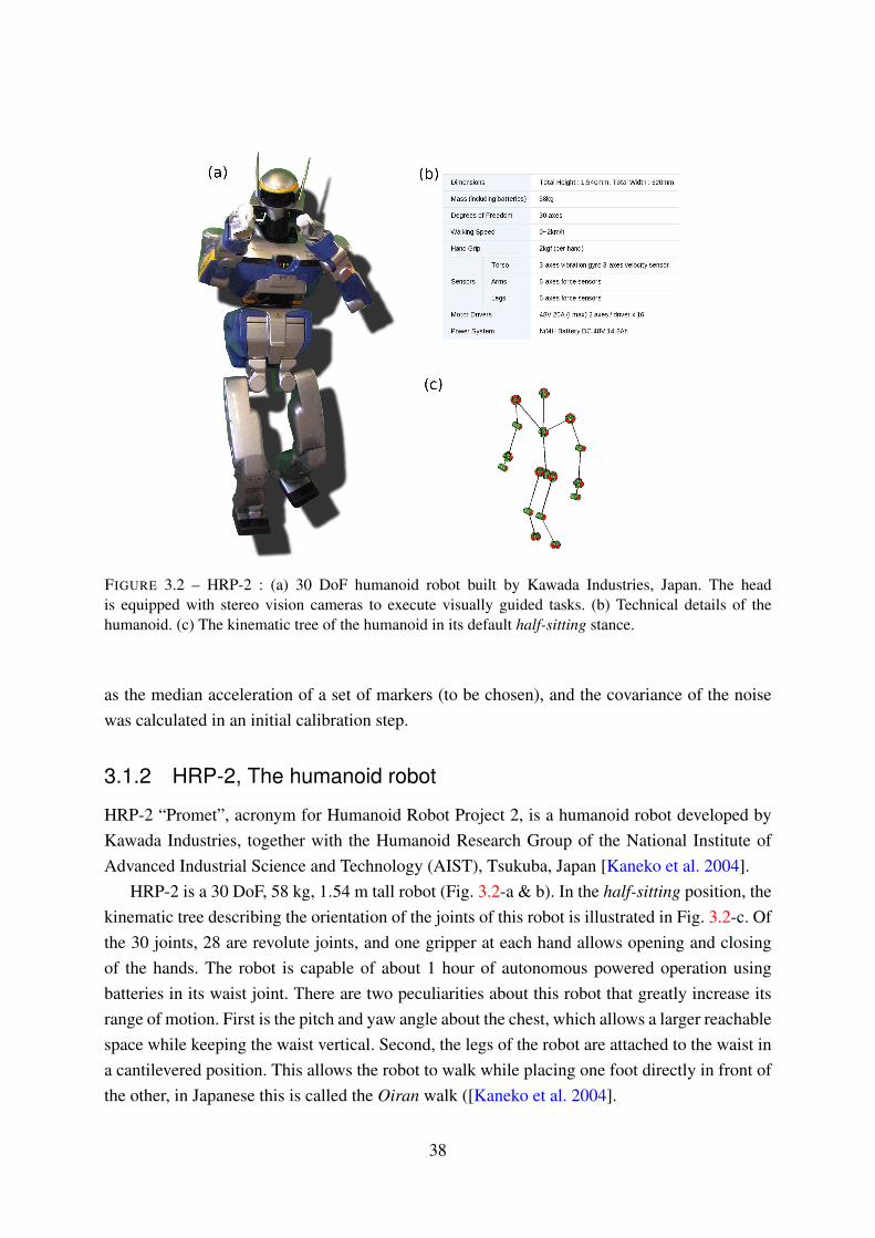
FIGURE 3.2 – HRP-2 : (a) 30 DoF humanoid robot built by Kawada Industries, Japan. The head
is equipped with stereo vision cameras to execute visually guided tasks. (b) Technical details of the
humanoid. (c) The kinematic tree of the humanoid in its default half-sitting stance.
as the median acceleration of a set of markers (to be chosen), and the covariance of the noise
was calculated in an initial calibration step.
3.1.2 HRP-2, The humanoid robot
HRP-2 “Promet”, acronym for Humanoid Robot Project 2, is a humanoid robot developed by
Kawada Industries, together with the Humanoid Research Group of the National Institute of
Advanced Industrial Science and Technology (AIST), Tsukuba, Japan [Kaneko et al. 2004].
HRP-2 is a 30 DoF, 58 kg, 1.54 m tall robot (Fig. 3.2-a & b). In the half-sitting position, the
kinematic tree describing the orientation of the joints of this robot is illustrated in Fig. 3.2-c. Of
the 30 joints, 28 are revolute joints, and one gripper at each hand allows opening and closing
of the hands. The robot is capable of about 1 hour of autonomous powered operation using
batteries in its waist joint. There are two peculiarities about this robot that greatly increase its
range of motion. First is the pitch and yaw angle about the chest, which allows a larger reachable
space while keeping the waist vertical. Second, the legs of the robot are attached to the waist in
a cantilevered position. This allows the robot to walk while placing one foot directly in front of
the other, in Japanese this is called the Oiran walk ([Kaneko et al. 2004].
38

Chapter 3 · Transferring human movements to a humanoid robot · § 3.2
Capable of a walking speed of around 2 km/h, HRP-2 has a 3-axes vibration gyro and 3-
axes velocity sensor situated in its torso. Further 6-axes force sensors are available in its feet
and both wrists. Under usual operation all algorithmic processing is conducted onboard the
two computers, ’C’ & ’V’ embedded inside HRP-2’s chest. The V computer handles higher
level processing while the C computer runs on real-time ART linux and controls the lower
level functions of the robot. Tasks requiring vision are conducted using onboard stereo-vision
cameras situated in the robot’s head.
HRP-2 also comes with a built-in stabilizer which maintains balance of the humanoid.
The inputs to the stabilizer are the reference ZMP position, waist attitude and whole-body
configuration of the robot. The current state of the robot is taken into account using the joint
angles, torso IMU, and the force sensor values from the robot’s feet. These inputs are then
used to modify the lower DoFs (i.e. the two legs) of the robot such that it maintains balance. In
practice, the stabilizer is provided as a black box and we do not have access to its inner functions
and exact architecture.
3.2 Direct imitation of human movements
In §1.3 we introduced some studies that implement motion imitation between humans and
humanoids (and virtual actors) using a variety of approaches, for example [Schaal et al. 2001;
Pettre and Laumond 2006; Dariush et al. 2008; Suleiman et al. 2008; Yamane and Hodgins
2009]. In the present study, some of these ideas were extended to implement real-time motion
imitation between a human actor and the humanoid robot HRP-2. The basis of this approach
can be condensed into two parts :
• Taking inspiration from the concept of a normalized skeleton in computer graphics
[Multon et al. 2008], a Humanoid-Normalized model was developed to act as an
intermediary motion conduit between the human and the humanoid.
• The original idea of an anticipation model was motivated by results in human neuroscience.
The purpose of the model was to allow the humanoid to imitate the movements of a human
balancing on one foot. The shifting of support foot was helped by taking into account
previous motion of the human head, and the humanoid’s Center of Mass (CoM).
Humanoid-Normalized model
[Multon et al. 2008] proposed the use of a normalized skeleton, which acts as an intermediate
entity to map motion between two different digital actors. The generation and adaptation
of motion was done by assuming that there exist planes formed by the arms and legs. The
normalized skeleton was represented by normalized segments, limbs of variable lengths and the
spine.
39

FIGURE 3.3 – Human→Humanoid Normalized Model→Humanoid. Motion capture position data from
the human is transferred in real-time to the normalized model and associated with the planes and
humanoid joints. The motion of these planes and joints drives the humanoid motion. Source [Montecillo-
Puente et al. 2010]
This idea was extended in this study by defining additional planes for the head, chest and
waist. The physical model of the upper body was built from the Cartesian positions of 22
markers on the human Fig. 3.3. Before the model was computed marker positions were scaled
according to a modified version of a standard scaling algorithm [Boulic et al. 2009]. The planes
were then attached to the human body in such a way that they could be directly used to define
tasks in a prioritized inverse kinematics solver. A combination of the orientation of these planes,
and the position of the extremities (head and wrists) formed the elements of the Humanoid-
Normalized model. These elements were then applied to tasks and constraints on the kinematic
chain of the humanoid robot.
Stack of tasks
The motion for each joint was generated from a prioritized stack of tasks, which was solved
using the inverse kinematics formulation explained in §2.2.2. Each element of the Humanoid-
Normalized model, was used as the reference input for the tasks. Four kinds of tasks were used :
position task, orientation vector task, homogeneous transformation task and a CoM task. The
task stack was defined as (in decreasing priority) :
1. Homogeneous transformation task for each feet, i.e. both position and orientation are
fixed,
2. Position task for Center of Mass (CoM) projection (X and Y positions),
3. Position task for the head,
4. Homogeneous transformation task for the left and right wrist,
5. Orientation vector task for the chest,
6. Orientation vector task for the waist,
40

Chapter 3 · Transferring human movements to a humanoid robot · § 3.2
FIGURE 3.4 – Scenario 1. (a) Snapshot of human dancing and its imitation by HRP-2 (b) Roll, pitch and
yaw angles of the head joint during the dancing motion. Solid black line indicates the angles of the HN
model, this was the reference that the humanoid had to follow. Red circles indicate the corresponding
angular value on HRP2 (c) Chest angles of the HN model (solid black line) and the corresponding angles
on the humanoid (dashed red line). Source [Montecillo-Puente et al. 2010]
7. Orientation vector task for the head.
CoM Anticipation Model
The relationship between the CoM and ZMP of a humanoid robot from the perspective of
maintaining dynamic balance was discussed in §2.3. The problem in this study was to decide
when to start shifting the CoM during the double support stance, and how to manipulate it during
single support stance. The solution to this was inspired from results in human neuroscience
research. Studies have reported strategies by which motion of the head in humans, can be related
to the CoM, foot placement and hip orientation [Patla et al. 1999; Vallis and McFadyen 2005].
The important result from these studies is that there is an anticipatory head movement which
precedes the motion of the rest of the body while stepping. In pilot experiments similar behavior
was found in the movements of this study’s human participants. This anticipatory motion was
vital to the approach as it could be used as a cue to prepare the humanoid for transitioning from
double to single support stance.
The projection of the humanoid CoM on the floor was manipulated by making it track a
calculated reference. The reference position was computed from the human head velocity and
the humanoid feet positions. Depending on the current stance of the HN model, i.e. Double
or Single Support the control law for calculating the reference position was switched. Fig. 3.5
shows the strategy at work.
41

FIGURE 3.5 – Scenario 2. (a) Picture of humanoid imitating the human lifting his foot. (b) Sideways
displacement of the HN model head (solid black line), and the vertical height of the humanoid’s lifting
foot (dashed red line). Also shown is the Y displacement of the humanoid’s CoM (dash-dot blue line).
Zoom inset shows a magnified view of the anticipation phase. The anticipation occurs between the
’Balance point’ and the time when the humanoid lifts its foot. Source [Montecillo-Puente et al. 2010]
HRP-2 Experiments
The motion imitation framework was implemented using the software GIK (see §2.4 for more
details). In the first scenario the robot’s feet positions were fixed and it imitated the motion of a
human performer executing a slow dance with the upper body, including bending of the knees
and ankles. Fig. 3.4-b & c show the roll, pitch and yaw angles of the head and chest of the HN
model and those of the humanoid robot. In the second scenario, the human performer was asked
to balance on one foot. Fig. 3.5-a shows the human and the humanoid balancing on one foot
(SS stance). The motion of the head in the HN model, and the vertical position of the foot of
the humanoid is plotted in Fig. 3.5-b. It was observed that the head shifts towards the support
foot (right foot) before the lifting the other foot. The sideways displacement of the head reaches
the Y position of the support foot about ∼ 1 s before foot lift. The video of the results can be
accessed at §7.
3.3 Using human movement primitives to drive robot reaching
motions
In §1.3 we introduced the concept of movement primitives as a means to easily represent
complicated human movements. In the field of biological motor control, it has been suggested
that the Central Nervous System (CNS) of primates uses a finite set of elementary motor
components, called primitives, to generate movements. The general ideas proposed here find
support in numerous and extensive studies (for example [Alexandrov et al. 1998; Lacquaniti
et al. 1999; Thomas et al. 2005; Kaminski 2007]).
42

Chapter 3 · Transferring human movements to a humanoid robot · § 3.3
FIGURE 3.6 – (a) Experimental environment : The participants were required to touch a target at the end
of a stick with their fingers. The position of the target was manipulated by the experimenter. Inset (right
top) shows the current position of the target (green sphere) and the next target (red sphere). Using real-
time feedback of the current position the experimenter positioned the stick during the experiment. (b)
An illustration of the placement of the virtual grids relative to the participant position. Each participant
executed 993 movements such that all 32 targets were reached from each other. Source [Tuan et al. 2010]
The goal of this study was to generate realistic humanoid reaching motions by looking at
how humans organize the same. The realism of the movement was judged by observing the
similarity in its kinematic characteristics, i.e. almost straight trajectories with a possible weak
regular curvature, and bell-shaped velocity profiles. In order to extract movement primitives we
first recorded a large database of human reaching movements.
Movement database generation
Arm movements of 3 participants were recorded using infrared markers attached to the shoulder,
elbow and wrist (Fig. 3.6 & 3.7-a). Participants were asked to perform a set of reaching
movements while standing up. 32 target positions (Fig. 3.7-b, regularly spaced in two parallel
grid were considered, such that the center of the grids was aligned to the participant’s shoulder.
The target was placed at one of the 32 positions, and the participants heard a sound to indicate
that they should start moving their hand to the target. Upon reaching the current target, the next
target was chosen randomly from the other 31 positions, and the experimenter moved the stick
to the new position.
Extraction of primitives
From the recorded human database, 6 angular values were extracted for each movement (other
DoFs were not considered). All movements were discretized to 100 data points and normalized
to 1 s duration. The primitive extraction problem was then expressed as determining K time-
functions such that for all m = 1, ...,M, it is possible to determine k real coefficients αmk ,
verifying :
43

FIGURE 3.7 – (a) Positioning of the reflective markers used to record reaching movements of the human
arm (b) Representation of the 32 target positions on two parallel virtual grids. These target positions were
used to drive the human reaching movements. Source [Tuan et al. 2010]
Um(t) =K
∑k=1
αmk Φk(t)
where, Um(t)∈R6 describes a database of M movements, with m= 1, ...,M, t ∈ [0,T ]. Functions
Φk(t) represent the expected primitives and the coefficients αmk are weighting the contribution
of each primitive Φk(t) into the movement Um(t).
This problem was solved using Principle Component Analysis (PCA) which has already
found application in neuroscience and robotics [Alexandrov et al. 1998; Thomas et al. 2005;
Sanger 2000; Lim et al. 2005]. It was observed that for K = 8 primitives, the variance accounted
for (VAF) was more than 96%, while it was 99.5% with K = 20. The reconstructed trajectories
were then compared to the original ones by using Root Mean Squared Error (RMSE), expressed
as,
RMSE =
√
E
(M×6× J)
where, E =E(αmk ,Φk) was the reconstruction error relative to the M movements of the database,
and J was the number of sampling elements for each movement. Using this measure, the number
of primitives can be easily chosen. For example, for the first participant it was found that with
K = 16, the RMSE was about 0.02 radians, (1.2◦).
Generalizing Movements
To generate almost straight trajectories with bell-shaped velocity curves, αk was chosen such
that the minimum jerk condition was satisfied [Flash and Hochner 2005]. This was implemented
as an optimization problem whose objective was to characterize the αk coefficients that allow
to minimize the mean error between the computed hand trajectory and the reference minimum-
44

Chapter 3 · Transferring human movements to a humanoid robot · § 3.4
jerk curve in the Cartesian space. Additional inequality constraints to the optimization were the
upper and lower bounds of the robot joints.
Experiments
The generalization approach was tested by generating a large number of new movements.
Fig.3.8 shows the characteristics of movements obtained with the robot arm, for K =
6,8,10,12,20. The hand trajectories and the velocity curves were not realistic for K = 6 and
8. However, as K increases, the trajectory becomes straighter and the velocity curve becomes
smoother and more regular. For K = 20 the velocity profiles were perfectly bell-shaped and
the hand trajectories almost straight with a continuous weak curvature. A video of the motion
capture and robot experiments can be accessed at §7.
FIGURE 3.8 – Description of the movement for the same reaching task of amplitude 58 cm, generated by
successively increasing the number of primitives K = 6, 8, 10, 12, and 20. From left to right, each row
corresponds to a particular value of K and represents : the Cartesian hand coordinates, the hand velocity
profile, the joint trajectories and the hand trajectory. The reaching errors in cm are respectively : 4.07,
1.14, 0.36, 0.12 and 0.11. Source [Tuan et al. 2010]
45

3.4 Discussion
In this chapter we first looked at some details of infrared-camera based motion capture
technology, and we were introduced to the humanoid robot HRP-2. Both of these are recurring
themes in this thesis and form the basis for recording human movements and for showcasing
the final motion, respectively. We then presented an overview of two studies that used
these technologies to show how human movements can be transferred to a humanoid robot.
In the context of motion planning for highly redundant robots, dimensionality reduction
and generalizability are attractive attributes. One of the advantages is lower computational
requirements which result in the possibility of implementing quicker and more reactive planning
algorithms. As the capacities and associated skills required of robots become progressively
complex, these attributes become important to make robots more adaptive.
In the first case, a motion imitation framework was developed that allows the humanoid
HRP-2 to reproduce a wide range of human movements in real-time. The key contributions of
this study were real-time transfer using a Humanoid-Normalized model, and the novel idea of
a CoM anticipation model. Additionally, with regard to other whole-body real-time imitation
approaches (e.g. [Dariush et al. 2008; Yamane and Hodgins 2009]), this study was different as
we do not consider the torso as one segment but allow independent chest and waist motions, as
well as leg motions. Here, the human movements were encoded by defining an appropriate
normalized model with reduced dimensions than the original movements. Additionally an
anticipation model was used which brings together results from human neuroscience and
practical application on a real humanoid robot. Other than the possible applications of direct
imitation, the results teach us a couple of more important things. We see how just a few
kinematic tasks coupled with ZMP constraints, when correctly defined and treated, can be easily
used to generate stable whole-body motions of a complex humanoid robot. Also we can now
judge how setting task priorities affect the execution of that task relative to others. These points
give us some clues as to the direction we have to take in order to better generate humanoid
motion from human movements.
Imitation in humans is a powerful learning tool and the mechanisms behind this has been the
focus of much research. Consequently, in the field of social robotics, imitation plays a strong
role in developing behaviors for a robot, as well as for picking up motion cues from the humans
it is imitating. In the context of the present study, it is important to note that the imitation
here is more direct, with no allowance for anticipation of human movements. The anticipation
implemented in the CoM motion was driven by a lower-level requirement of stability, rather than
a higher-level cognitive reasoning. Critically speaking, imitating human movements essentially
disregards any cues within those movements that can tell us more about their purpose and
intention. Also in the case of highly dynamic movements, this imitation method would fail.
Hence, to better understand what makes our movements human, and to consequently
46
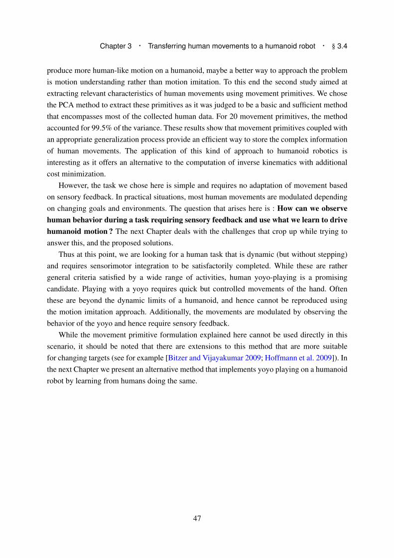
Chapter 3 · Transferring human movements to a humanoid robot · § 3.4
produce more human-like motion on a humanoid, maybe a better way to approach the problem
is motion understanding rather than motion imitation. To this end the second study aimed at
extracting relevant characteristics of human movements using movement primitives. We chose
the PCA method to extract these primitives as it was judged to be a basic and sufficient method
that encompasses most of the collected human data. For 20 movement primitives, the method
accounted for 99.5% of the variance. These results show that movement primitives coupled with
an appropriate generalization process provide an efficient way to store the complex information
of human movements. The application of this kind of approach to humanoid robotics is
interesting as it offers an alternative to the computation of inverse kinematics with additional
cost minimization.
However, the task we chose here is simple and requires no adaptation of movement based
on sensory feedback. In practical situations, most human movements are modulated depending
on changing goals and environments. The question that arises here is : How can we observe
human behavior during a task requiring sensory feedback and use what we learn to drive
humanoid motion ? The next Chapter deals with the challenges that crop up while trying to
answer this, and the proposed solutions.
Thus at this point, we are looking for a human task that is dynamic (but without stepping)
and requires sensorimotor integration to be satisfactorily completed. While these are rather
general criteria satisfied by a wide range of activities, human yoyo-playing is a promising
candidate. Playing with a yoyo requires quick but controlled movements of the hand. Often
these are beyond the dynamic limits of a humanoid, and hence cannot be reproduced using
the motion imitation approach. Additionally, the movements are modulated by observing the
behavior of the yoyo and hence require sensory feedback.
While the movement primitive formulation explained here cannot be used directly in this
scenario, it should be noted that there are extensions to this method that are more suitable
for changing targets (see for example [Bitzer and Vijayakumar 2009; Hoffmann et al. 2009]). In
the next Chapter we present an alternative method that implements yoyo playing on a humanoid
robot by learning from humans doing the same.
47

4From human to humanoid yoyo playing
AS children (and even some adults) many of us have played with a yoyo for fun. If you
were to hand a yoyo to a naive person, chances are that he/she will make mistakes at
the beginning but pretty soon be able to make stable oscillations. There is thus something that
humans learn about the dynamic characteristics of the yoyo and how manipulating the motion
of their hands can affect them.
While it does not seem to be a complicated task to learn, in reality, manipulating a yoyo
involves a complex interplay between sensing its position, estimating its future behavior and
coordinating one’s motor action to compensate for perturbations while maintaining stable
oscillations. Keeping this in mind, yoyo playing for a humanoid robot is a challenging task
for several reasons. First, there is little formal understanding of the basic control laws that
humans apply to perform cyclic tasks such as yoyo playing including the amount and type of
feedback. Second, compared to a human, humanoid robots are relatively slow, capable of only
small accelerations and a limited range of motion. Hence, a direct transfer of human maneuvers
by simply replaying the recorded motion on a humanoid would not work. And third, the sensors
and controllers available even on a state-of-the-art humanoid robot are quite different from what
nature has offered humans.
There are other cyclic tasks involving the manipulation of a ball such as juggling and
dribbling which have received a lot of attention in robotics [Buehler and Koditchek 1990; Schaal
and Atkeson 1993; Batz et al. 2009]. The fundamental difference between ball manipulation
49

and yoyo playing is that juggling and dribbling have free flying phases where the ball and
the hand move independently, while the yoyo always remains connected to the hand by the
string. Several authors have studied yoyo playing from a robotics perspective. [Hashimoto and
Noritsugu 1996], proposed a model to control a yoyo by a robot based on vision feedback.
An improved model with 2 DoF (Degrees of Freedom) and four phases was used by [Jin
and Zacksenhouse 2002] to study energy loss due to collisions. The authors later proposed
a switching control strategy and use visual feedback and state estimation to implement yoyo
motion on a manipulator [Jin and Zacksenhouse 2004]. Yoyo motions of different amplitudes
were implemented on a robotic arm, using a 1 DoF yoyo model, by Zlajpah and Nemec [Zlajpah
and Nemec 2003].
Compared to the robots used in these studies, a humanoid robot not only has a more complex
kinematic structure, but also unique characteristics that are both a constraint and an advantage
to its overall capabilities. For example, a typical humanoid is not capable of the kind of precise
high-speed motion that robotics arms can accomplish. In addition, a humanoid, being bipedal,
has to maintain its stability while executing all motions and for the same reason cannot execute
the non-smooth control laws proposed by previous authors.
FIGURE 4.1 – (a) Human yoyo playing motion recorded via motion capture technology (left), is used to
teach the humanoid HRP-2 (right) (b) HRP-2 grasps the yoyo in its hand, and inset shows the same yoyo
with the reflective motion capture markers used in the motion capture experiments
In the following section we explain the recording and analysis of the human motion capture
experiments. A precise dynamic model of the yoyo is then developed from motion capture data
by using optimal parameter estimation. The derived model is then used to generate trajectories
that are within the kinematic and dynamic limits of the humanoid HRP-2. Finally, we present
experiments on the humanoid that show stable yoyo-playing.
50

Chapter 4 · From human to humanoid yoyo playing · § 4.1
4.1 Measuring human yoyo motion
Human yoyo playing was recorded using the aid of motion capture technology. The experimental
area was a 5× 5 m well lit empty space equipped with an optical tracking system (Motion
Analysis Corporation, USA) and all data were output in a reference frame centered in the
capture volume (see §3.1.1 for more details). The yoyo used was a professional grade free-
wheeling type (Duncan Wheels, Duncan, USA) weighing 66 gm. Three miniature reflective
tracking markers were attached to the yoyo in order to track its trajectory during the oscillations
(see Fig. 4.1-b). Two markers were attached symmetrically to one side of the yoyo, and the third
marker was set in the middle of the other side. The reason for attaching two markers to one side
was because we wished to calculate the rotational of the yoyo during oscillations (see Fig. 4.2).
Marker positions were adjusted such that they caused minimal perturbation during oscillations.
Experimental protocol
To track the movement of the participants, we used 8 tracking markers as shown in Fig. 4.1-a. In
total we measured yoyo action of four participants, all of whom had previous experience with
playing yoyos. All participants chose to use their right hand and were free to choose the finger
on which to tie the yoyo string. They were asked to elevate their hand, instead of just lifting the
finger, while playing the yoyo. This was necessary due to the lack of finger articulation on our
humanoid robot HRP-2. Participants were instructed to play the yoyo at their preferred speed in
a smooth fashion, and to not re-grasp the yoyo between trials. Before recording, all participants
were given about 5 minutes to practice yoyo oscillations with the given instructions. None of the
participants reported any difficulty playing with the yoyo in this manner. For each participant,
we recorded three trials, each containing 90 seconds of up-down yoyo motion. Additional trials
were recorded for blindfolded yoyo playing and other tricks like ’sleeper’ etc. The focus of this
study was the simple up-down yoyo trials.
Data Analysis
For the purpose of the model defined in the following sections, we needed the following three
parameters from the recorded experimental data,
• Vertical height of human hand
• Vertical height of yoyo
• Rotational angle of yoyo
The first two were directly measured and available. For the vertical yoyo height, we used
the single marker on one side since this was closest to the yoyo’s (vertical) center. Both these
measures were low-pass filtered at 10 Hz to reduce electronic noise (3rd degree, zero phase
shift Butterworth filter). Calculating the rotational angle of the yoyo as it rolled on its axis and
51

translated in space was a more challenging task. This was primarily due to the high rotational
speed of the yoyo (around 60 rotations per second at mid-oscillation).
Fig. 4.2-a shows the profile view of the motion of markers A and B attached to one side
of the yoyo. In order to detect one full rotation we need at least two recorded frames where
A and B are in different angular quadrants. Since we were recording motion at 100 Hz, this
was easy during slow rotational phases (begin and end of cycle). However, while rotating at
maximum speeds, the resolution of motion capture was close to its limits. At such times, the
system fails to match the current pose of the markers and either returns no value, or worse the
same information as the previous frame. This was detrimental as it could lead us to estimate a
wrong (normally lower) value for the rotational angle during an oscillation.
We cannot simply filter the position data, since the markers rotate as well as translate
in space. Modifying (filtering) this positional data would lead to even more losses while
calculating the rotational angles. To solve this problem we implemented a filter at the level
of rotational accelerations.
First, oscillations were automatically segmented by detecting the yoyo peak height, as
shown in Fig. 4.2-b. Then for each oscillation the progression of the rotational angle, φ , was
computed as shown in Fig. 4.2-a. Rotational angle was defined as starting from zero at the
start and continuously increasing till the end of that oscillation. This initial estimate was not
reliable due to the reasons outlined before. In order to improve our estimate, we first calculated
rotational accelerations as,
α = ω = φ
where, ω is the rotational velocity of the yoyo. Instances where the motion capture failed to
record a change in marker positions would result in very large changes in rotational acceleration.
These were detected using a threshold value that was chosen by observing the acceleration
pattern. Fig. 4.2-c shows the detected peaks of acceleration. At each of these points we rejected
the calculated value and interpolated between the last and next reliably known accelerations.
Typically, we had to interpolate for only a few frames at a time. From the corrected and
interpolated acceleration values, we recalculated the rotational angle φ (Fig. 4.2-d). The shape
of the progression of rotational angle corresponded well with what would be expected during an
oscillation, i.e. slow rotation at the beginning, smoothly transitioning into faster rotations and
again slowing down towards the end.
For each subject we calculate the above parameters for all segmented oscillations. From this
data we chose 10 oscillations per subject where the acceleration profile required the least amount
of corrections. Note that the chosen oscillations need not have been necessarily consecutive. The
final data set, as shown in Fig. 4.3, was then used to identify the human yoyo control scheme
52

Chapter 4 · From human to humanoid yoyo playing · § 4.2
FIGURE 4.2 – Analysis of yoyo motion : (a) Illustration of profile view of yoyo during oscillations. The
cartesian positions of the two markers, A and B, attached to the side of the yoyo were used to calculate
the rotational angle. Proportional changes are exaggerated in this figure for easier illustration. (b) Time
course of hand and yoyo vertical heights over several oscillations. Squares indicate the detected peaks in
yoyo height. The bold lines stand for the currently segmented oscillation with corresponding data in the
next two panels. (c) Filtering erroneous rotational acceleration using a threshold value (horizontal dotted
lines). (d) Recomputed rotational angle after filtering.
as well as unknown yoyo parameters. This is explained in the following sections, but first we
present the dynamic equations that describe the yoyo motions during an oscillation.
4.2 Dynamic model of a yoyo
Even though a yoyo seems to be a quite simple mechanism, the correct description of its
dynamics is not that straightforward. A complete description involves multiple phases, state
dependent phase switching events, discontinuities of variables at impacts, friction effects etc.
The yoyo motion is powered by the motion of the guiding hand which transfers energy to the
yoyo either by directly imposing its motion to the yoyo during the short contact phase, or - when
53
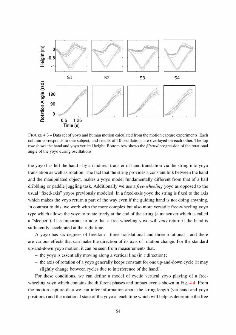
FIGURE 4.3 – Data set of yoyo and human motion calculated from the motion capture experiments. Each
column corresponds to one subject, and results of 10 oscillations are overlayed on each other. The top
row shows the hand and yoyo vertical height. Bottom row shows the filtered progression of the rotational
angle of the yoyo during oscillations.
the yoyo has left the hand - by an indirect transfer of hand translation via the string into yoyo
translation as well as rotation. The fact that the string provides a constant link between the hand
and the manipulated object, makes a yoyo model fundamentally different from that of a ball
dribbling or paddle juggling task. Additionally we use a free-wheeling yoyo as opposed to the
usual “fixed-axis” yoyos previously modeled. In a fixed-axis yoyo the string is fixed to the axis
which makes the yoyo return a part of the way even if the guiding hand is not doing anything.
In contrast to this, we work with the more complex but also more versatile free-wheeling yoyo
type which allows the yoyo to rotate freely at the end of the string (a maneuver which is called
a “sleeper”). It is important to note that a free-wheeling yoyo will only return if the hand is
sufficiently accelerated at the right time.
A yoyo has six degrees of freedom - three translational and three rotational - and there
are various effects that can make the direction of its axis of rotation change. For the standard
up-and-down yoyo motion, it can be seen from measurements that,
– the yoyo is essentially moving along a vertical line (in z direction) ;
– the axis of rotation of a yoyo generally keeps constant for one up-and-down cycle (it may
slightly change between cycles due to interference of the hand).
For these conditions, we can define a model of cyclic vertical yoyo playing of a free-
wheeling yoyo which contains the different phases and impact events shown in Fig. 4.4. From
the motion capture data we can infer information about the string length (via hand and yoyo
positions) and the rotational state of the yoyo at each time which will help us determine the free
54
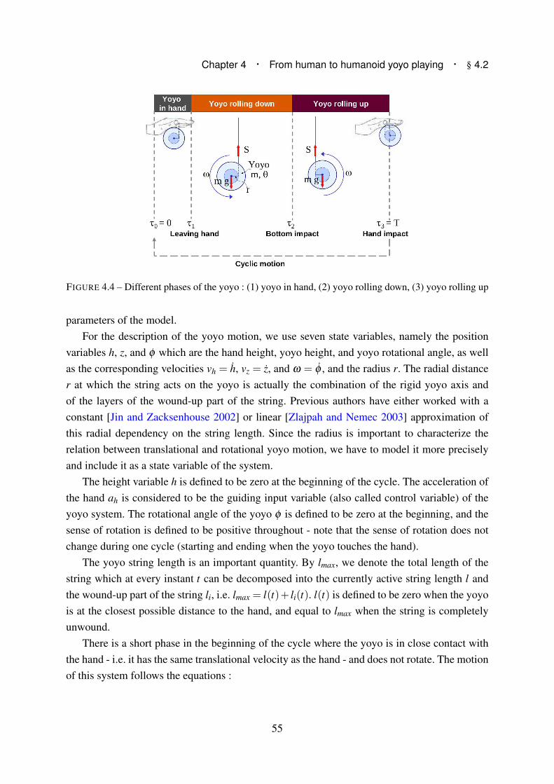
Chapter 4 · From human to humanoid yoyo playing · § 4.2
FIGURE 4.4 – Different phases of the yoyo : (1) yoyo in hand, (2) yoyo rolling down, (3) yoyo rolling up
parameters of the model.
For the description of the yoyo motion, we use seven state variables, namely the position
variables h, z, and φ which are the hand height, yoyo height, and yoyo rotational angle, as well
as the corresponding velocities vh = h, vz = z, and ω = φ , and the radius r. The radial distance
r at which the string acts on the yoyo is actually the combination of the rigid yoyo axis and
of the layers of the wound-up part of the string. Previous authors have either worked with a
constant [Jin and Zacksenhouse 2002] or linear [Zlajpah and Nemec 2003] approximation of
this radial dependency on the string length. Since the radius is important to characterize the
relation between translational and rotational yoyo motion, we have to model it more precisely
and include it as a state variable of the system.
The height variable h is defined to be zero at the beginning of the cycle. The acceleration of
the hand ah is considered to be the guiding input variable (also called control variable) of the
yoyo system. The rotational angle of the yoyo φ is defined to be zero at the beginning, and the
sense of rotation is defined to be positive throughout - note that the sense of rotation does not
change during one cycle (starting and ending when the yoyo touches the hand).
The yoyo string length is an important quantity. By lmax, we denote the total length of the
string which at every instant t can be decomposed into the currently active string length l and
the wound-up part of the string li, i.e. lmax = l(t)+ li(t). l(t) is defined to be zero when the yoyo
is at the closest possible distance to the hand, and equal to lmax when the string is completely
unwound.
There is a short phase in the beginning of the cycle where the yoyo is in close contact with
the hand - i.e. it has the same translational velocity as the hand - and does not rotate. The motion
of this system follows the equations :
55

h = z = vh (4.1)
φ = 0 (4.2)
which in the full form with seven state variables becomes :
h = vh (4.3)
z = vz (4.4)
φ = ω (4.5)
vh = ah (4.6)
vz = ah (4.7)
ω = 0 (4.8)
r = 0 (4.9)
with the initial conditions :
z(τ0) = h(τ0)+∆h (4.10)
vz(τ0) = vh(τ0) (4.11)
φ(τ0) = ω(τ0) = 0. (4.12)
∆h is the small offset between hand and yoyo mid point, occurring when the two are at close
contact.
After a very short time (which was estimated to be t = τ1 = 0.1 s) the yoyo leaves the hand
and starts its rolling down phase. In this phase, (4.3) - (4.6) remain valid, but the last three
equations change. The rolling motion induces the following kinematic coupling to the velocity
variables vh, vz and ω :
l = vh − vz = ωr
→ l = vh − vz = ω r+ ωr,
→ vz + ωr = ah −ω r (4.13)
The dynamic equations of the yoyo in translational and rotational directions can be written
as :
56

Chapter 4 · From human to humanoid yoyo playing · § 4.2
mvz = S−mg
Θω = Sr− γrω
where, m and Θ are the mass and moment of inertia of the yoyo. S is the force in the string
(see Fig. 4.4), and the last term in the latter equation is a velocity dependent friction term with
constant γ . Elimination of S results in the dynamic equation :
Θω −mrvz = mgr− γrω (4.14)
For the radial distance at which the string acts on the yoyo we can assume that its change is
proportional to the angular velocity of the yoyo (due to the snail-like way the string winds about
the axis). In the rolling down phase, the radius decreases, and the angular velocity by definition
is positive. We therefore obtain :
r =−ρ ω (4.15)
where the parameter ρ > 0 remains to be determined.
The rolling down phase lasts until the bottom impact event at t = τ2 when the string reaches
its maximum length,
sbottomimpact = l − lmax = h− z−∆h − lmax = 0 (4.16)
i.e. this event does not depend explicitly on time, but on the state of the yoyo system. It can be
assumed that the motion of the hand is smooth, but the impact generates discontinuities of the
velocities of the yoyo vz and ω of the following form :
ω(τ+2 ) = βω(τ−2 ) with β < 1 (4.17)
vz(τ+2 ) =
{
vh(τ+2 )+ω(τ+2 )r if (ah(τ
−2 )≥ bah
)
vh(τ+2 ) else
(4.18)
Eqn. (4.17) assumes that the loss of rotational motion can be captured by a constant factor
β (to be determined from measurements). Eqn. (4.18) takes into account the property of a free-
wheeling yoyo that if no sufficient upward acceleration is generated before bottom impact, then
it will remain in a freely rotating - i.e. sleeping - mode at the end of the string. If on the other
hand the upward acceleration is high enough, the yoyo will go into the up-winding phase. Here
we are interested in the latter case. The lower bound of this acceleration depends on many
factors, such as the tightness of the string about the yoyo axle which also changes during the
57

play, but we work here with an estimation of bah= 3 m/s2. With this estimation we remain on
the safe side for motion generation, since we observed that humans never had to exceed that
value at the bottom point.
The rolling up phase is defined by similar equations as the rolling down phase but with some
sign changes of the terms. The sense of rotation remains unchanged (positive), but the active
string length now shortens as a function of the rotation, i.e. the kinematic equation becomes
l = vh − vz =−ωr
→ vz − ωr = ah +ω r (4.19)
The dynamic equation also changes to,
Θω +mrvz =−mgr− γrω, (4.20)
and the radius equation becomes
r = ρ ω . (4.21)
Again, (4.3) - (4.6) remain valid. The phase ends when the yoyo is back in the hand at
t = τ3 = T which is implicitely defined by the switching function,
shand impact = l = h− z−∆h = 0, (4.22)
and the cycle is closed by appropriate impact equations to match the initial conditions (4.10) -
(4.12). Periodicity constraints are considered to generate a cyclic motion :
(h(T ),z(T ),vh(T ),r(T )) = (h(0),z(0),vh(0),r(0)) (4.23)
Periodicity of vz is automatically implied via (4.23) and (4.11), and periodicity of ω via the
hand impact equations that eliminate all rotation of the yoyo. φ is by definition reset to zero
after each cycle.
For the yoyo used in the human experiments, only the yoyo mass could be directly measured,
and was m = 0.066 kg. The inertia Θ of the yoyo can only be roughly estimated and is identified
by computations. The same is true for the impact coefficient β , the friction coefficient γ and the
radial parameter ρ . Maximum string length lmax and yoyo-hand offset depend on the way the
yoyo is attached to the hand of each subject and will also be identified from measurements (see
next section).
[Jin and Zacksenhouse 2002] have proposed the inclusion of an additional transition phase
after bottom impact where no rolling occurs and z and φ are independent. However, for the
58
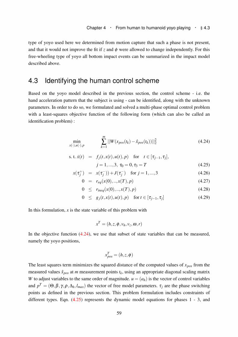
Chapter 4 · From human to humanoid yoyo playing · § 4.3
type of yoyo used here we determined from motion capture that such a phase is not present,
and that it would not improve the fit if z and φ were allowed to change independently. For this
free-wheeling type of yoyo all bottom impact events can be summarized in the impact model
described above.
4.3 Identifying the human control scheme
Based on the yoyo model described in the previous section, the control scheme - i.e. the
hand acceleration pattern that the subject is using - can be identified, along with the unknown
parameters. In order to do so, we formulated and solved a multi-phase optimal control problem
with a least-squares objective function of the following form (which can also be called an
identification problem) :
minx(·),u(·),p
m
∑k=1
||W (xpos(tk)− xpos(tk))||22 (4.24)
s. t. x(t) = f j(t,x(t),u(t), p) for t ∈ [τ j−1,τ j],
j = 1, ...,3, τ0 = 0,τ3 = T (4.25)
x(τ+j ) = x(τ−j ))+ J(τ−j ) for j = 1, ...,3 (4.26)
0 = req(x(0), ..,x(T ), p) (4.27)
0 ≤ rineq(x(0), ..,x(T ), p) (4.28)
0 ≤ g j(t,x(t),u(t), p) for t ∈ [τ j−1,τ j] (4.29)
In this formulation, x is the state variable of this problem with
xT = (h,z,φ ,vh,vz,ω,r)
In the objective function (4.24), we use that subset of state variables that can be measured,
namely the yoyo positions,
xTpos = (h,z,φ)
The least squares term minimizes the squared distance of the computed values of xpos from the
measured values xpos at m measurement points tk, using an appropriate diagonal scaling matrix
W to adjust variables to the same order of magnitude. u = (ah) is the vector of control variables
and pT = (Θ,β ,γ,ρ,∆h, lmax) the vector of free model parameters. τ j are the phase switching
points as defined in the previous section. This problem formulation includes constraints of
different types. Eqn. (4.25) represents the dynamic model equations for phases 1 - 3, and
59

FIGURE 4.5 – Match between human experiments and identified model for all four subjects s1 - s4 : thin
grey lines show 10 measured cycles, black dots their average, and solid lines show computational results.
(4.26) the state variable jumps between those. Eqn. (4.27) and (4.28) are point-wise equality
and inequality constraints. They may describe conditions to a single point, such as starting
equation (4.10) or switching point conditions equation (4.16), or conditions relating different
points to each other, such as periodicity conditions (4.23). Eqn. (4.29) represents continuous
inequality constraints on all variables, such as bounds on state and control variables, which are
not relevant in this section, since they are not reached in the case of human yoyo playing, but
they become relevant in the next section where humanoid yoyo playing is considered.
For the solution of this multi-phase optimal control problem, we use a direct approach based
on a piecewise constant control discretization as implemented in the code MUSCOD ([Bock
and Plitt 1984; Leineweber et al. 2003]). State parametrization is accomplished by the multiple
shooting method which splits the long integration interval into many smaller ones and with
that transforms the original boundary value problem into a set of initial value problems with
corresponding continuity and boundary conditions. This technique is highly efficient and allows
the solution of the described yoyo problem in approximately 1 second.
Such an identification problem is solved individually for each of the four subjects. For each
subject we use data of 10 different yoyo cycles out of a nearly cyclic motion (as calculated in
§4.1), and from this obtain average cyclic data xpos. Motion data of subjects can not be combined
since every subject has its own characteristic way of playing yoyo, i.e. uses its individual control
scheme. However, since all are playing with the same yoyo, we do expect to identify the same
60

Chapter 4 · From human to humanoid yoyo playing · § 4.4
yoyo parameters Θ, γ , β and ρ from the experiments. Parameters lmax and ∆h again are subject
specific, since they depend on the particular way of attaching the yoyo to the hand, and on the
marker position on the subjects hand.
Fig. 4.5 presents the solutions of the four optimal control problems identifying the cyclic
motions of the four subjects with trajectories for hand and yoyo height in the left column, and for
the rotational angle in the right column. The thin lines show the 10 different measurements for
each subject, while the solid thick lines show the computed trajectories, which nearly perfectly
match the average data. It can therefore be concluded that the model results in a very good
approximation of the experiments. The table in Fig.4.6, shows the resulting yoyo parameters
for all subjects as well as the average values which can now be used for the following yoyo
computations.
FIGURE 4.6 – Resulting parameter data for subjects s1 - s4, and average values.
4.4 Adapting motion to humanoids
The yoyo playing trajectories of human players studied in the previous section cannot
directly be transferred to the humanoid robot HRP-2. The required hand motion is not feasible
within the tight ranges on position, velocity and acceleration of the robot. We therefore
generated new yoyo playing motion which respected the following bounds of HRP-2 :
−0.24 m ≤ h ≤ 0.16 m (4.30)
i.e. 0.94 m−1.34 m above ground
−1.6 m/s ≤ vh ≤ 1.6 m/s (4.31)
−10.5 m/s2 ≤ ah ≤ 10.5 m/s2 (4.32)
as well as the condition that the yoyo should stay well above the floor,
61
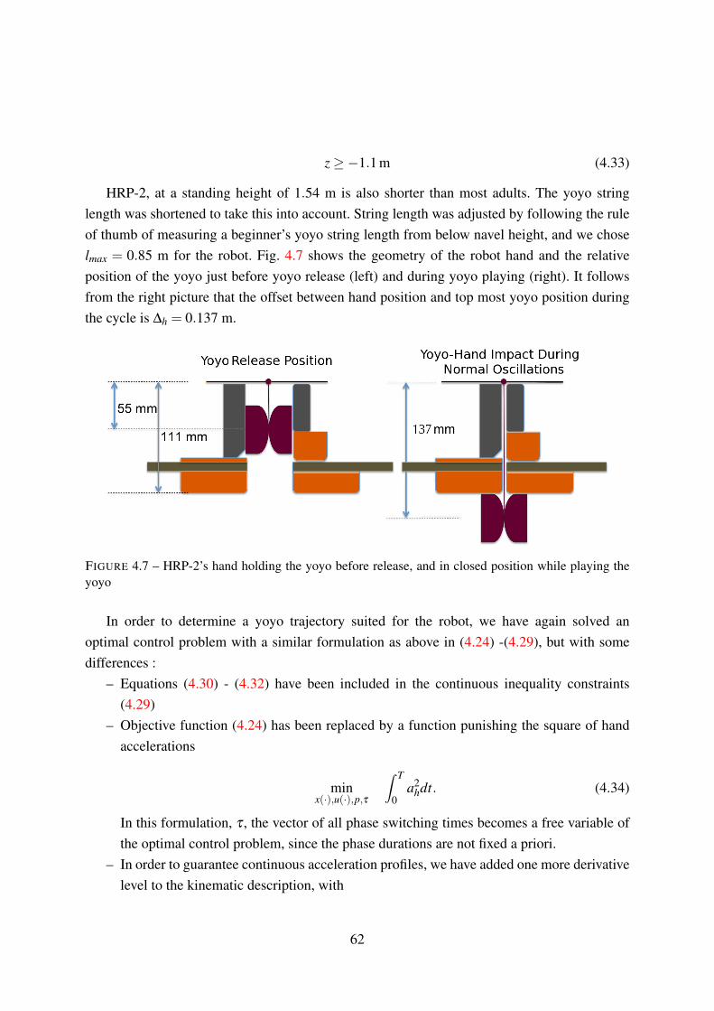
z ≥−1.1 m (4.33)
HRP-2, at a standing height of 1.54 m is also shorter than most adults. The yoyo string
length was shortened to take this into account. String length was adjusted by following the rule
of thumb of measuring a beginner’s yoyo string length from below navel height, and we chose
lmax = 0.85 m for the robot. Fig. 4.7 shows the geometry of the robot hand and the relative
position of the yoyo just before yoyo release (left) and during yoyo playing (right). It follows
from the right picture that the offset between hand position and top most yoyo position during
the cycle is ∆h = 0.137 m.
FIGURE 4.7 – HRP-2’s hand holding the yoyo before release, and in closed position while playing the
yoyo
In order to determine a yoyo trajectory suited for the robot, we have again solved an
optimal control problem with a similar formulation as above in (4.24) -(4.29), but with some
differences :
– Equations (4.30) - (4.32) have been included in the continuous inequality constraints
(4.29)
– Objective function (4.24) has been replaced by a function punishing the square of hand
accelerations
minx(·),u(·),p,τ
∫ T
0a2
hdt. (4.34)
In this formulation, τ , the vector of all phase switching times becomes a free variable of
the optimal control problem, since the phase durations are not fixed a priori.
– In order to guarantee continuous acceleration profiles, we have added one more derivative
level to the kinematic description, with
62

Chapter 4 · From human to humanoid yoyo playing · § 4.4
FIGURE 4.8 – Optimal smooth yoyo playing trajectory for HRP-2 with continuous hand acceleration
profile, respecting bounds on h, vh and ah
ah = jh (4.35)
where the jerk jh now becomes the new control variable of the problem (which is
discretized as a piecewise constant function) and ah the eighth state variable (which
consequently is piecewise linear and continuous). To ensure continuity of the accelerations
between cycles, we add a fifth periodicity constraint to (4.23),
ah(T ) = ah(0) (4.36)
Fig. 4.8 shows the resulting plots of all eight state variables for periodic yoyo motions. All
bounds are satisfied, but while velocity and acceleration stay clear of the imposed bound, the
possible range of hand height positions is nearly fully exploited. We also computed a special
starting cycle that allows us to bring the yoyo from its static release position (compare Fig. 4.7)
to the periodic target orbit in one oscillation.
In order to implement more diverse yoyo playing motions on the humanoid robot, we have
also investigated the variations of trajectories with respect to different frequencies, i.e. different
cycle times. This can be achieved for the same string length by different hand motion cycle
frequencies. In order to determine these different solutions, we repeatedly solve the optimal
control problem described above with objective function (4.34), each time fixing the total time
τ3 = T to the chosen value. It is a simple task to additionally provide transition trajectories
63

FIGURE 4.9 – (a) Cycle time variations of yoyo playing trajectories for HRP-2 (b) Hand and yoyo
trajectories for different string lengths lmax
between the different cyclic trajectories and thus enable the robot to vary between slower and
faster yoyo playing. The results for several different cycle times are shown in Fig. 4.9-a.
We also have investigated the dependency of the robot trajectories on the chosen string
length lmax. For each of these string lengths, different solutions with different cycle times could
be generated ; here we have chosen to compare solutions with the optimal cycle times (with
respect to criterion (4.34)) for each string length (see Fig. 4.9-b).
4.5 HRP-2, world’s first humanoid to play the yoyo !
The humanoid HRP-2 was introduced in the previous chapter (§3.1.2). While not all of its
30 DoFs are required to execute the yoyo motion, a majority of the DoFs are also involved
in maintaining balance. For a cyclic motion like playing the yoyo, the humanoid hand is
outstretched like a cantilever and moved at close to its velocity limitations. The critical need
here is to stabilize the robot while managing to execute the generated hand trajectory.
During yoyo playing, humans stabilize the yoyo between oscillations by letting it strike
their hand smoothly without introducing any perturbations. Comparatively, HRP-2’s hand is
an uneven gripper offering no damping whatsoever to a rebounding yoyo. Thus, we first had
to solve the practical problem of hand-yoyo impacts on HRP-2 before implementing any
calculated motion. Any solution would also have to take into account that the yoyo would have
to be released from the same hand in a controlled manner and with precise timing.
64

Chapter 4 · From human to humanoid yoyo playing · § 4.5
After testing various solutions we settled on the simple construction of two halves of
damping sponges attached to the grippers (see Fig. 4.7). Before release, the yoyo was held
between the grippers and suspended from a small inflexible stick attached to the top of the wrist.
The wrist is kept horizontal during release, and throughout the oscillation, to cause minimal
swinging action in the sagittal plane. After yoyo release, the grippers rapidly close and present
the rebounding yoyo with a flat and soft surface on which to impact.
There are different options on how to implement the solutions on a humanoid robot :
– A fully Open-loop approach : replay the computed reference hand trajectories while
respecting the initial conditions.
– An Event-based Open-loop strategy : a detection of impacts between phases (at the
bottom and at the hand) can be used for timing corrections of the executed trajectory
(i.e .the trajectory is executed phase-wise). This mode is also similar to the biologically
motivated strategy proposed in [Jin and Zacksenhouse 2002].
– A Closed-loop approach using vision feedback : yoyo height and/or string length can
be constantly tracked using either the robot’s own vision system or an external source
like a motion capture system. This type of feedback information matches the amount of
information that humans may use for yoyo playing.
Here, we detail the implementation and results obtained from the first approach. For
the other two control strategies we have to deal with implementation problems like data
transmission delays and robust signal detection. These are the focus of current work and here
we detail the proposed solutions.
4.5.1 Open Loop Control
Humanoid whole-body motion was generated using the GIK software introduced in §2.4. Hand
trajectory were calculated offline for every 10 ms time step and applied to HRP-2’s wrist as a
position task defined as,
fh(θ) = Pth −Ph(θ)
where, fh(θ) is the position task, Pth is the reference position and Ph(θ) the current position of
the hand expressed as a function of the robot’s DoF’s θ .
Pilot trials showed that allowing the chest to move (pitch and yaw) did not significantly
increase the maximum possible vertical hand speed. Thus, in the final trials we only used the
arm DoFs for the motion. Executing the computed motion on HRP-2, lead to an average of
6-7 oscillations. Fig. 4.10-a shows snapshots of HRP-2 during one oscillation at the important
stages of yoyo and hand motion. Fig. 4.10-b plots the theoretical (reference) motion of HRP-
2’s hand and yoyo, and the values that were actually recorded by motion capture. The yoyo
65
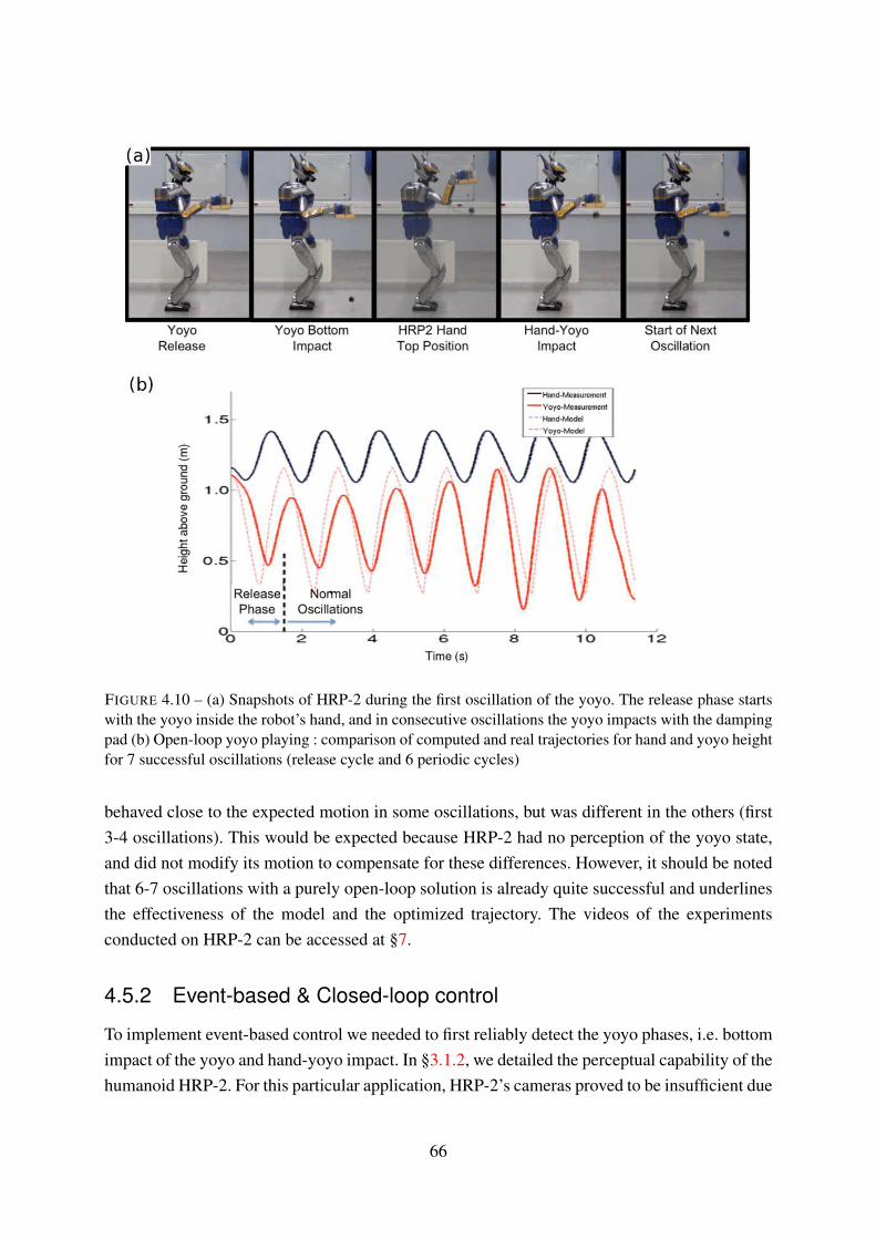
FIGURE 4.10 – (a) Snapshots of HRP-2 during the first oscillation of the yoyo. The release phase starts
with the yoyo inside the robot’s hand, and in consecutive oscillations the yoyo impacts with the damping
pad (b) Open-loop yoyo playing : comparison of computed and real trajectories for hand and yoyo height
for 7 successful oscillations (release cycle and 6 periodic cycles)
behaved close to the expected motion in some oscillations, but was different in the others (first
3-4 oscillations). This would be expected because HRP-2 had no perception of the yoyo state,
and did not modify its motion to compensate for these differences. However, it should be noted
that 6-7 oscillations with a purely open-loop solution is already quite successful and underlines
the effectiveness of the model and the optimized trajectory. The videos of the experiments
conducted on HRP-2 can be accessed at §7.
4.5.2 Event-based & Closed-loop control
To implement event-based control we needed to first reliably detect the yoyo phases, i.e. bottom
impact of the yoyo and hand-yoyo impact. In §3.1.2, we detailed the perceptual capability of the
humanoid HRP-2. For this particular application, HRP-2’s cameras proved to be insufficient due
66

Chapter 4 · From human to humanoid yoyo playing · § 4.5
to slow acquisition rate and data processing delays. Vision information was instead provided by
the motion capture system by using the reflective markers on the yoyo. However, the information
about the yoyo position was delayed by ∼ 100 ms due to data transmission delays. Hence we
needed to come up with a suitable control scheme that accounts for this delay. Due to occlusions
it was also possible to lose yoyo position data, for example when it impacts on HRP-2’s hand
on rebound. To have continuous information we implemented a kalman filter that estimates
yoyo position during short periods of data loss. This filter was identical to that explained in
the § 3.1.1. Additionally, we supplemented the visual data with the information coming from
HRP-2’s force and torque sensors embedded in the wrist.
FIGURE 4.11 – Profile view of HRP-2’s hand. The 6-axis force and torque sensor was used to detect
the change in tension in the string at the point of bottom impact. Here, S stands for sensor frame, and
C for the hand center of mass frame. This information was supplemented by the motion capture system
tracking the yoyo markers.
As explained earlier, the yoyo was suspended from a string attached to the top of HRP-2’s
wrist Fig. 4.7. Fig. 4.11 shows the profile view of this arrangement. With a static hand, both
force and torque sensors were sensitive enough to record the change in string force due to yoyo
bottom impact. However, moving HRP-2’s arm generates additional signals due to the changing
gravity vector, hand accelerations and noise due to mechanical vibrations. Filtering these signals
to detect the accurate yoyo impact is a signal processing problem.
We first canceled out the force and torque generated due to gravity and the hand’s
acceleration. The equations used to calculate this are provided in the Annex 7. The remaining
components were due to the tension S, of the yoyo string, and we aimed to detect this change
in tension as the yoyo string stretched to maximum length (bottom impact). The force, fext ,
and torque next , components were filtered using a moving window average of 5 epochs. These
averaged values were then normalized using a nominal value estimated during a previous
calibration stage. The normalized forces and torque were added together and compared against
67
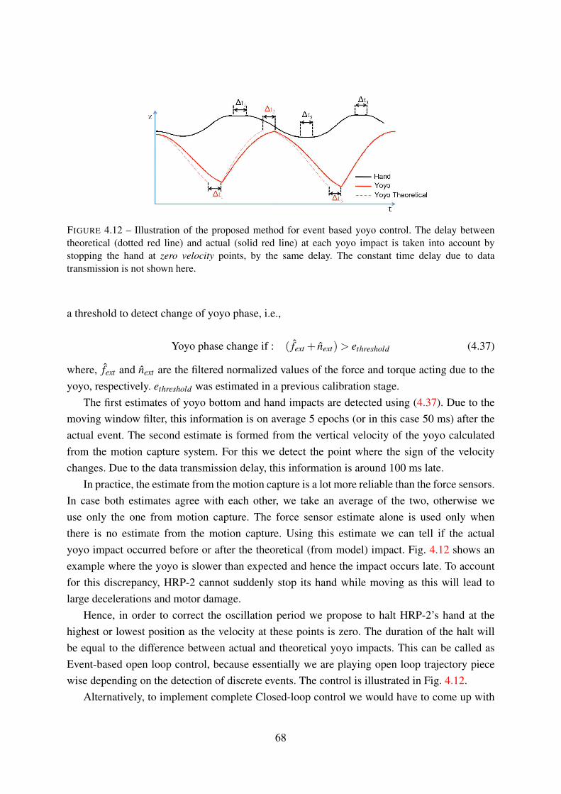
FIGURE 4.12 – Illustration of the proposed method for event based yoyo control. The delay between
theoretical (dotted red line) and actual (solid red line) at each yoyo impact is taken into account by
stopping the hand at zero velocity points, by the same delay. The constant time delay due to data
transmission is not shown here.
a threshold to detect change of yoyo phase, i.e.,
Yoyo phase change if : ( fext + next)> ethreshold (4.37)
where, fext and next are the filtered normalized values of the force and torque acting due to the
yoyo, respectively. ethreshold was estimated in a previous calibration stage.
The first estimates of yoyo bottom and hand impacts are detected using (4.37). Due to the
moving window filter, this information is on average 5 epochs (or in this case 50 ms) after the
actual event. The second estimate is formed from the vertical velocity of the yoyo calculated
from the motion capture system. For this we detect the point where the sign of the velocity
changes. Due to the data transmission delay, this information is around 100 ms late.
In practice, the estimate from the motion capture is a lot more reliable than the force sensors.
In case both estimates agree with each other, we take an average of the two, otherwise we
use only the one from motion capture. The force sensor estimate alone is used only when
there is no estimate from the motion capture. Using this estimate we can tell if the actual
yoyo impact occurred before or after the theoretical (from model) impact. Fig. 4.12 shows an
example where the yoyo is slower than expected and hence the impact occurs late. To account
for this discrepancy, HRP-2 cannot suddenly stop its hand while moving as this will lead to
large decelerations and motor damage.
Hence, in order to correct the oscillation period we propose to halt HRP-2’s hand at the
highest or lowest position as the velocity at these points is zero. The duration of the halt will
be equal to the difference between actual and theoretical yoyo impacts. This can be called as
Event-based open loop control, because essentially we are playing open loop trajectory piece
wise depending on the detection of discrete events. The control is illustrated in Fig. 4.12.
Alternatively, to implement complete Closed-loop control we would have to come up with
68

Chapter 4 · From human to humanoid yoyo playing · § 4.6
a method to continuously modulate the hand trajectory. The modulation would depend on the
instantaneous (but delayed) difference between actual and theoretical yoyo motion. We propose
the use of a minimum jerk filter minimizing the difference in operational space. The advantage
in this method is that we can try to maintain the theoretical motion while ensuring smooth
transitions in case of errors.
4.6 Discussion
The final goal of the study in this Chapter, was to make a humanoid robot play the yoyo. An
important contribution was in the way this was achieved. To do this we first tried to understand
how humans easily manipulate a yoyo to maintain stable oscillations. By recording several
humans playing the yoyo we built a knowledge base of successful yoyo oscillations and the
associated hand movements that made this possible. From this an optimal control problem
was solved that identified the control scheme of the hand as well as some parameters in the
multi-phase dynamic model of the yoyo. We showed that the established yoyo model and an
appropriate choice of inputs and model parameters resulted in very good approximation of the
experimental data. This model formed the basis for the generation of feasible yoyo motions for
HRP-2 respecting its bounds on hand position, velocities and accelerations. The implementation
of the open-loop strategy showed 6-7 successful oscillations.
In contrast to the tasks in the previous Chapter (§3.2 & §3.3), yoyo playing was presented as
a more dynamic task requiring continuous motor control. In humans, this control is modulated
using visual feedback of the yoyo, sensing the force in the string and the proprioception of
the arm joints. For robotic yoyo playing, we proposed an analogous strategy by detecting the
switching points of the oscillation. The implementation of this and the closed-loop strategy is
the focus of on-going work.
The motivation behind choosing to model the yoyo task was that it was a simple, yet
dynamic, human movement. The modeled dynamics, optimization of parameters and applied
control strategies are specific to the system being manipulated, i.e. the yoyo. However, in the
general scheme there are several human tasks that require repetitive and dynamic modulation
of movements where the present approach could find application. An example of such a task is
stable locomotion where humans repeat the action of dynamically changing their feet placement
while shifting their weight. Modeling the detailed dynamics of locomotion is a much more
challenging task than the yoyo, although recent research has begun to tackle this [Mombaur
2008]. Within the context of the present study, using information from human locomotion to
intelligently guide and control humanoid locomotion could be an interesting extension of these
methodologies.
69

Summary of Part I of this thesis
Part I of this thesis concentrated on analyzing human movements to define or complete models
that were then used to generate humanoid motion. In §3.2 we saw an overview of an open-
loop implementation of a humanoid robot imitating human movements. Here, there was no
analysis and the role of the model developed was to simply manipulate the movements into
a form suitable for the humanoid. In order to move towards approaches that analyze and try
to understand human movements, we presented a second study in §3.3. Here, arm reaching
movements in humans were represented using movement primitives. From these, generalized
motions were generated that were applied on a humanoid robot. This idea of using human
movements to better define and guide humanoid motion was interesting within the context of
this thesis, and formed the basis for the approach in Chapter 4.
In Chapter 4 we chose a task that required more dynamic manipulation than the reaching
task considered earlier. We used the successful manipulation of a yoyo by human participants
to complete a dynamic model of the yoyo. This model was then utilized to generate suitable
yoyo motions within a humanoid robot’s limitations. In this case, the “goal” or “target” was to
maintain stability of a dynamic system (yoyo) by modulating the hand behavior.
70

Part II : Modeling goal-driven locomotion
So far we have significantly simplified our modeling problems by only considering tasks that
require arm movements or hand trajectories. The issue of dynamic bipedal stability was not
formally addressed. The question that we would now like to pose is : How, and what, can we
learn from human movements that involve locomotion ?
In Part II of this thesis we deal specifically with the issue of learning from humans in order to
better organize locomotion in humanoid robots. It is important to note that it is not sufficient to
simply process the movements of the whole-body during locomotion in the same way as we have
done so far for hand or arm movements. This is because of the nature of the anthropomorphic
structure that adds the additional requirement of dynamic bipedal stability during locomotion.
In the approaches detailed in the following chapters, we come closer to results and tools from
the field of human neuroscience. At the same time we rely strongly on robotics concepts of
tasks and constraints as defined for kinematic chains (see §2.2.2).
By developing both of these in parallel and then linking them together we provide a unique
approach towards using human walking to organize humanoid locomotion. First, we borrow the
principle of head stabilization in humans to implement head-driven stepping on a humanoid
robot. The ”goal or target” in this case is provided by a user manipulating the robot via a
joystick. To complement the results of this approach we then provide a formal way to represent
human movements during a walking and grasping task. In contrast to the previous scenario,
the target here is to grasp an object by walking towards it. The invariants extracted from these
movements are then applied as kinematic tasks and constraints on the humanoid robot.
71


5Steering a humanoid robot by its head
OVER the past century, humans have significantly augmented the modes of transport
available to them, but walking still remains an important way of moving around in
the environment. The ability of legged locomotion makes humans versatile and allows us to
fulfill a wide variety of complex tasks. Scientific interest in the mechanisms behind human
locomotion has been proportional to its importance in our daily lives. Research has approached
the issue from various angles. At a bio-mechanical level there have been extensive studies on
the way joints and muscles work in cohesion. Often researchers use treadmills or large spaces
to simulate walking over long distances, using motion capture or inertial sensors to record
walking characteristics (as examples see [Andriacchi and Alexander 2000; Dingwell et al. 2001;
Menz et al. 2003; Sreenivasa et al. 2008; Noble and Prentice 2008]). Joint level data can be
supplemented with force plates to measure human Center of Pressure (CoP) during walking
to infer knowledge about the dynamics, for example [Jian et al. 1993]. Moving away from
joint level analysis, macroscopic walking behavior can also be characterized by looking at the
trajectory followed [Hicheur et al. 2007; Souman et al. 2009].
An alternative approach to studying human walking is to investigate the essential role played
by the various sensory systems. Walking requires a robust estimation of the environment and
the walker’s state, using the visual, vestibular and somatosensory senses among others. The
absence of, or malfunction in, one or more of these senses is highly detrimental to being able
to walk. For example, people have been shown to walk in circles when blindfolded or while
73

walking in visually degraded environments [Souman et al. 2009]. The vestibular system tells
the body about its balance and relation with respect to gravity (see [Day and Fitzpatrick 2005]
for an introduction to the vestibular system). Damage to the vestibular organs, or induced noise
in the sensors using galvanic stimulation, has been shown to severely affect the ability to walk
satisfactorily [Day et al. 1997]. The general evidence from these studies shows that walking, a
seemingly simple task we do everyday, is in fact a complex interplay between different parts of
the body and various sources of sensory information. In the context of this thesis, we thus need
to define a starting point to begin our foray into human locomotion.
The idea to utilize human walking knowledge in humanoid locomotion is not a new one.
Several studies in robotics have taken inspiration from human movements and embedded this
knowledge into humanoid walking [Boulic et al. 1990; Harada et al. 2009]. However, there is
no doubt still a large gap between the plethora of information from life sciences that is available
to roboticists, and that actually being applied.
FIGURE 5.1 – The robot perception-action loop as implemented in this approach : The human perceives
the robot’s environment and guides it. The role of the human is higher level control while the humanoid
plans local stable motions using a decision process. See Fig. 1.1 for the complementary human
Perception-Action Loop.
The anthropomorphic structure that humanoid robots share with humans, provide them with
several interesting properties. Probably the most powerful of these is the ability to walk. Legged
locomotion in humanoids has opened up various potential avenues of application where the
capability to step over obstacles is important. But due to the very fact that humanoids and
humans are roughly similar in structure, planning walking motion is a complicated task. So far
in this thesis we have put forward the argument that better understanding human movement may
help in organizing humanoid robot whole body motion. But understanding whole-body walking
in humans is a lot more complicated than the tasks we have dealt with so far. In this chapter, we
74
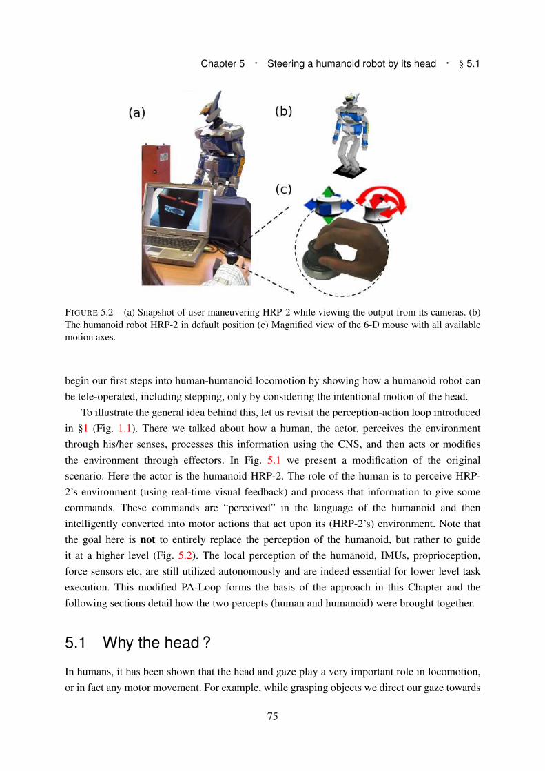
Chapter 5 · Steering a humanoid robot by its head · § 5.1
FIGURE 5.2 – (a) Snapshot of user maneuvering HRP-2 while viewing the output from its cameras. (b)
The humanoid robot HRP-2 in default position (c) Magnified view of the 6-D mouse with all available
motion axes.
begin our first steps into human-humanoid locomotion by showing how a humanoid robot can
be tele-operated, including stepping, only by considering the intentional motion of the head.
To illustrate the general idea behind this, let us revisit the perception-action loop introduced
in §1 (Fig. 1.1). There we talked about how a human, the actor, perceives the environment
through his/her senses, processes this information using the CNS, and then acts or modifies
the environment through effectors. In Fig. 5.1 we present a modification of the original
scenario. Here the actor is the humanoid HRP-2. The role of the human is to perceive HRP-
2’s environment (using real-time visual feedback) and process that information to give some
commands. These commands are “perceived” in the language of the humanoid and then
intelligently converted into motor actions that act upon its (HRP-2’s) environment. Note that
the goal here is not to entirely replace the perception of the humanoid, but rather to guide
it at a higher level (Fig. 5.2). The local perception of the humanoid, IMUs, proprioception,
force sensors etc, are still utilized autonomously and are indeed essential for lower level task
execution. This modified PA-Loop forms the basis of the approach in this Chapter and the
following sections detail how the two percepts (human and humanoid) were brought together.
5.1 Why the head ?
In humans, it has been shown that the head and gaze play a very important role in locomotion,
or in fact any motor movement. For example, while grasping objects we direct our gaze towards
75

FIGURE 5.3 – Behavior of head (and trunk) during turning : (a) Maximum relative yaw of the head with
respect to the heading and trunk. Error bars indicate standard errors of the mean across participants.
Time course of the head-trunk behavior during turning. Yaw (b) and yaw rate (c) of head (solid lines) and
trunk (dotted lines) over time relative to the previous straight-ahead direction. The curves were aligned
at the time of head anticipation (zero on time axis, shown by the dashed vertical line). The vertical solid
lines at around 0.25 s indicate the time when the trunk started to turn for the respective angles. Source
[Sreenivasa et al. 2008]
it [Johansson et al. 2001]. While reaching for objects out of immediate reach, it is suggested
that humans create a gaze centered reference frame [Flanders et al. 1999]. During dynamic
equilibrium, as well as locomotion, the head is stabilized in rotation about the yaw axis [Pozzo
et al. 1990; Pozzo et al. 1996]. This stabilization has been suggested to be useful for a more
stable reference frame for egocentric visual motion perception and better visual-vestibular
matching [Imai et al. 2001; Prevost et al. 2002; Hicheur et al. 2005].
Another aspect of head behavior during locomotion is the anticipation of changes in
trajectory. Research has shown that the head yaw angle anticipates body yaw (shoulder and
trunk) and shift in locomotor trajectory [Patla et al. 1999; Imai et al. 2001; Hicheur et al. 2005].
Simply put, the head looks into a turn before the rest of the body and before changing the
walking course. A previous study investigated this relationship between the head and trunk
by observing turns of different angles [Sreenivasa et al. 2008]. Fig. 5.3-a shows the main
results for turns from 45◦ to 180◦. As turn angle increased, the head looked further towards the
turning direction. Furthermore, the time evolution of the head yaw and yaw rate show smooth
modulation of the head behavior throughout the turns, Fig. 5.3-b & c. These results, taken in
conjunction with those from other studies on turning behavior suggest that the anticipatory
nature of head motion occurs in order to gather advance visual information about the trajectory
and potential obstacles [Grasso et al. 1998; Hollands et al. 2001; Prevost et al. 2002; Hicheur
et al. 2005; Sreenivasa et al. 2008].
Thus, anticipatory and stabilizing mechanisms modulate the movements of the head during
walking and underline the importance of head behavior. This is not surprising since the head
contains important sources of sensory information like vision and the vestibular canals. It would
76

Chapter 5 · Steering a humanoid robot by its head · § 5.2
be advantageous to have a stable and well-placed frame of sensory input. The general evidence
from these studies suggests that the control of the multiple degrees of freedom of the human
body during locomotion is organized from the head down, and not, as implemented in most
humanoid robots, from the feet up [Berthoz 2000].
In this chapter we propose the robotics analogy to this idea by tele-operating a humanoid
robot, including stepping, purely as a result of controlling its head. The idea of tele-operating a
humanoid robot has been considered before. One such study approached this issue by manually
choosing and switching control between the various joints of the humanoid robot [Neo et al.
2005; Neo et al. 2007]. While this does enable the user to control the robot, and accomplish a
range of stepping and reaching motions, it is still not a very intuitive approach and, in principle,
very different from how human motion is planned.
Here, we show that by only taking a 6-D input from a user (3 translations & 3 rotations, Fig.
5.2-c) and applying that to the head of a humanoid robot, we can generate deliberative whole
body motion of the robot. The experience of steering the humanoid robot is accentuated by
allowing the user to receive visual feedback about the environment from the robot’s perspective
(Fig. 5.2-a). The algorithm developed evaluates the intentional motion of the user from the
mouse input. The architecture detailed in the following sections brings this together with state-
of-the-art robotics approaches on step planning [Kajita et al. 2003] and inverse kinematics
[Nakamura 1991; Kanoun 2009].
5.2 Humanoid steering control algorithm
The primary goals of the control software were three fold :
1. Allow user to move the head of the robot in real time
2. Generate whole body motions in response to head motion
3. Check humanoid stability and generate stepping motions when required
Fig. 5.4 shows a simplified flowchart describing the various steps to implement these goals.
Here we describe the various components of the architecture in further detail.
5.2.1 Smoothing user input
We chose to use a 6 dimensional mouse (3DConnexion, Logitech) to record motion from a
user and transfer it to the head joint of the robot. Input from the mouse was a 6-D vector
consisting of 3 translational (x, y, z) and 3 rotational motions (roll, pitch, yaw). In order to
ensure a smooth motion transfer we first processed this vector using a minimum jerk filter.
The minimum jerk formulation used was based on the work by [Hoff and Arbib 1993]. Our
77
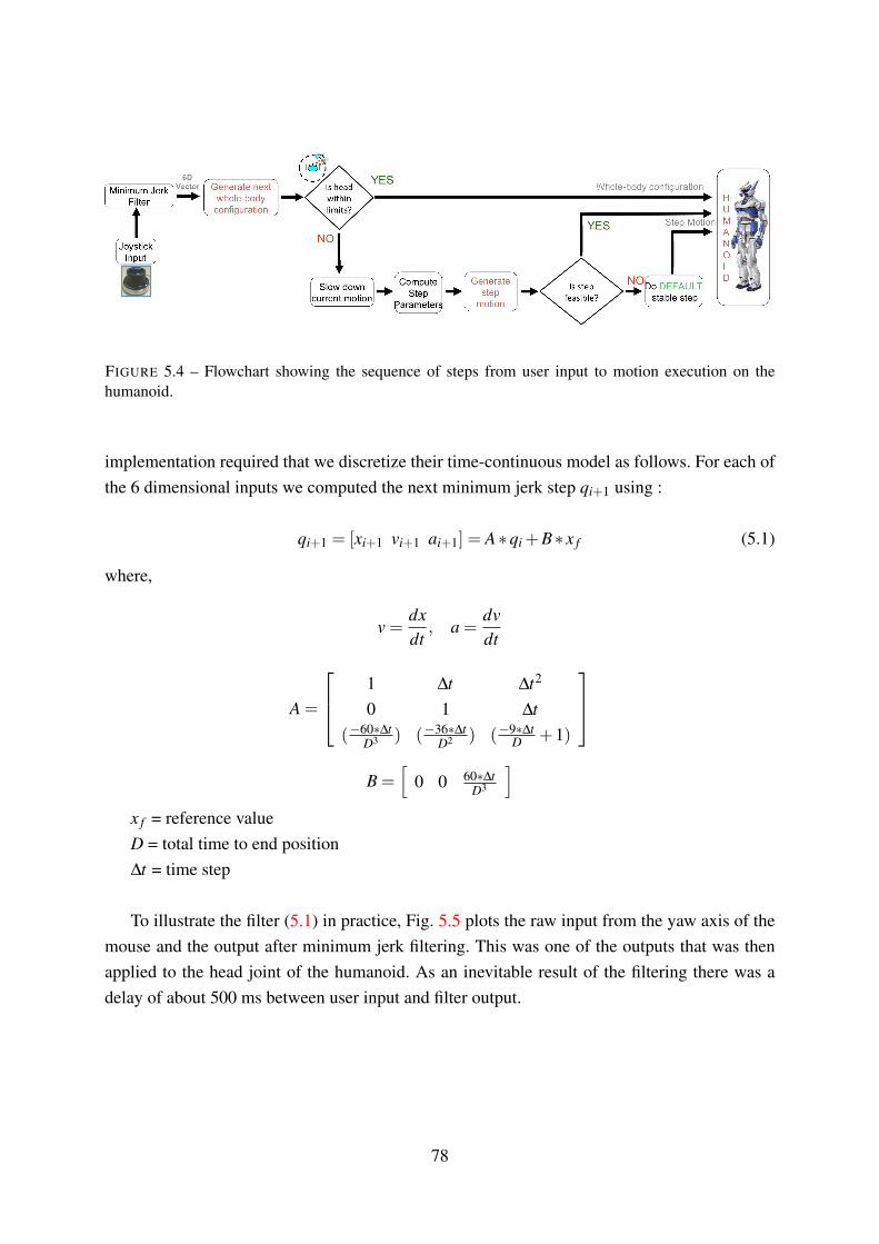
FIGURE 5.4 – Flowchart showing the sequence of steps from user input to motion execution on the
humanoid.
implementation required that we discretize their time-continuous model as follows. For each of
the 6 dimensional inputs we computed the next minimum jerk step qi+1 using :
qi+1 = [xi+1 vi+1 ai+1] = A∗qi +B∗ x f (5.1)
where,
v =dx
dt, a =
dv
dt
A =
1 ∆t ∆t2
0 1 ∆t
(−60∗∆tD3 ) (−36∗∆t
D2 ) (−9∗∆tD
+1)
B =[
0 0 60∗∆tD3
]
x f = reference value
D = total time to end position
∆t = time step
To illustrate the filter (5.1) in practice, Fig. 5.5 plots the raw input from the yaw axis of the
mouse and the output after minimum jerk filtering. This was one of the outputs that was then
applied to the head joint of the humanoid. As an inevitable result of the filtering there was a
delay of about 500 ms between user input and filter output.
78

Chapter 5 · Steering a humanoid robot by its head · § 5.2
FIGURE 5.5 – Input from the yaw axis of the 6-D mouse (dotted line) and the output after processing by
the minimum jerk model (solid line)
5.2.2 When and Where to step ?
If we were to simply move a humanoid’s head, it will eventually reach the limits of its stability
and fall. In our case we constrain the projection of the CoM to remain at the center of the
support polygon. This is done by using the available DoFs of the humanoid to counterbalance
the motion of the head and torso (for example, the hands move backwards as the head moves
forwards). Therefore, after a certain amount of head motion the humanoid will reach its joint
limits and not be able to execute the task any further. At this point, or preferably much earlier,
we need to re-stabilize the humanoid by bringing the head back or by making a step.
The conventional method to evaluate dynamic stability is to ensure that the ZMP remains
inside the support polygon of the robot. Theoretically, this means that the robot is stable in the
entire region defined by the support polygon. But in practice, if the ZMP is allowed to reach
the boundary of the support polygon, it becomes impossible to stop in time to avoid falling.
Additionally, if the head travels too far away from the center of the support polygon it will drag
the chest and waist along with it. In this posture, it is difficult to compute stable step motion
since the method proposed by [Kajita et al. 2003] assumes the waist to be close to vertical. To
avoid these problems we devised a method that answers two basic questions : When to step ?
and Where to step ?. The first question deals with distinguishing when the humanoid is at, or
close to, the limit of its movement range and the latter decides what future configuration will
create a more stable posture for further movements.
When to step ?
Stepping was triggered using two criteria. The first criterion was to detect when the projection
of the head position on the ground exceeded a certain limit, rsa f e. This limit was defined as
a circle centered at the middle of the support polygon (dotted circle in Fig. 5.6-a). When the
79

head projection on the floor reached the boundary of this circle, we decided to make a step.
In addition to this, stepping was activated when the yaw angle of the head crossed a threshold
value. This is shown as the shaded arc of circle in Fig. 5.6-a. The reason for this second trigger
was that if the head of the robot is turned, the chest and waist follow due to the weighting of
the inverse kinematics. For large turn angles the robot will reach a posture from which it is very
difficult to step. We avoided this situation by stepping after a certain threshold, θthreshold .
The thresholds, rsa f e and θthreshold are to be chosen conservatively after testing various
movement scenarios and depending on the capabilities of the humanoid robot in question. The
algorithm shown in Alg. 1 shows the implementation of the two triggers and corresponds to the
decision step ”Is head within limits ?” in Fig. 5.4.
Algorithm 1 When to step ? Computing stepping triggers
Require: rsa f e, θthreshold
loop
Compute
∆θHead = θHeadCurrent −θLe f tFoot−θRightFoot
2
∆XHead = XHead −XSupportPolygon
∆YHead = YHead −YSupportPolygon
r =√
(∆XHead)2 +(∆YHead)2
if (abs(∆θHead)> θthreshold) or (r > rsa f e) then
Compute step parameters → go to Algorithm 2
else
Compute whole-body configuration
end if
end loop
Where to step ?
After having detected the need to step, and before actually starting the step, we slowed down
the motion of the robot smoothly. This was done by setting a target velocity of zero for the head
and letting the minimum jerk filter (5.1) slow it down in a controlled manner. After stopping all
motion, we brought the chest and waist back to vertical position and planned stepping motions
from this upright posture.
At this point we have the intentional motion wanted by the user encoded in the parameters
∆θHead , ∆XHead and ∆YHead . From these parameters we calculated a suitable stepping position
that moved the robot in the appropriate direction. To do this we first have to decide which foot
to use for stepping. Usually this was done by picking the foot which lay in the direction of head
80
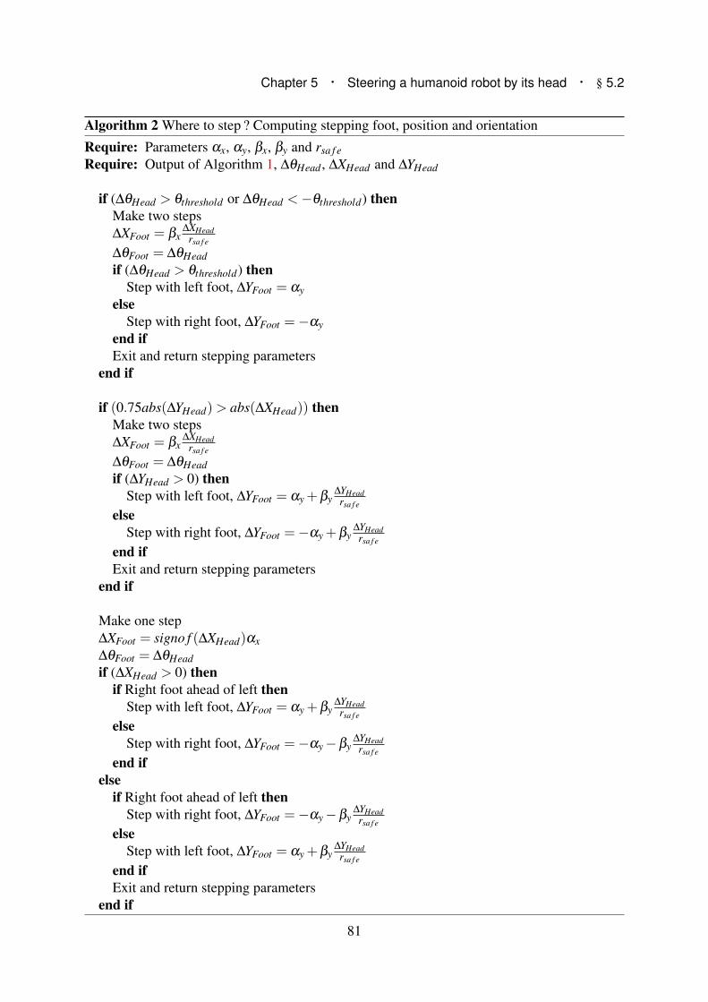
Chapter 5 · Steering a humanoid robot by its head · § 5.2
Algorithm 2 Where to step ? Computing stepping foot, position and orientation
Require: Parameters αx, αy, βx, βy and rsa f e
Require: Output of Algorithm 1, ∆θHead , ∆XHead and ∆YHead
if (∆θHead > θthreshold or ∆θHead <−θthreshold) then
Make two steps
∆XFoot = βx∆XHead
rsa f e
∆θFoot = ∆θHead
if (∆θHead > θthreshold) then
Step with left foot, ∆YFoot = αy
else
Step with right foot, ∆YFoot =−αy
end if
Exit and return stepping parameters
end if
if (0.75abs(∆YHead)> abs(∆XHead)) then
Make two steps
∆XFoot = βx∆XHead
rsa f e
∆θFoot = ∆θHead
if (∆YHead > 0) then
Step with left foot, ∆YFoot = αy +βy∆YHead
rsa f e
else
Step with right foot, ∆YFoot =−αy +βy∆YHead
rsa f e
end if
Exit and return stepping parameters
end if
Make one step
∆XFoot = signo f (∆XHead)αx
∆θFoot = ∆θHead
if (∆XHead > 0) then
if Right foot ahead of left then
Step with left foot, ∆YFoot = αy +βy∆YHead
rsa f e
else
Step with right foot, ∆YFoot =−αy −βy∆YHead
rsa f e
end if
else
if Right foot ahead of left then
Step with right foot, ∆YFoot =−αy −βy∆YHead
rsa f e
else
Step with left foot, ∆YFoot = αy +βy∆YHead
rsa f e
end if
Exit and return stepping parameters
end if
81

FIGURE 5.6 – When & Where to step ? Figures not to scale : (a) Dotted circle and shaded arc of circle,
show the range of motion of head position and yaw, respectively, without needing to step. (b) As the head
crosses the circle a stepping configuration is calculated based on current head position and orientation.
The shaded rectangle represents the future position of the foot.
motion. For example, in Fig. 5.6-a the head is translated and rotated towards the right and we
therefore chose the right foot to step. Fig. 5.6-b shows the configuration of the right foot, before
and after stepping. However, this will not work in all cases. For example, if the right foot is
already forward, and the user moves further to the right, then it makes more sense to use the
left foot and rotate it towards the right. Things become more complicated when you have to
take into account backward or lateral steps, or when the direction of translation and rotation are
dissimilar.
To solve this problem we developed an algorithm that decides the stepping foot and the
relative step size, as a sequence of decisions. Alg. 2 shows the main steps involved in this
process. Given ∆θHead , ∆XHead and ∆YHead from the previous phase (Alg. 1), the aim of this
algorithm is to decide the stepping foot and calculate ∆θFoot , ∆XFoot and ∆YFoot . In order to
calculate the step position the algorithm requires us to define four parameters, αx, αy, βx and
βy. αx and αy decide the basic step size depending on the minimum safe distance between the
two feet, and the maximum stepping distance achievable by the humanoid. βx and βy are used
to tune the extent to which head displacement modifies foot placement.
First, steps were classified as Turning Steps if the absolute difference between the head
direction and mean direction of the feet, was larger than θthreshold . Stepping foot was chosen by
looking at the direction of head turn, i.e. turning head left = step with left foot, and vice versa.
For this type of stepping we rotated the stepping foot by the same amount as the head. Then
a second step brings the other foot parallel to the first step. Basically, at the end of these two
steps, the robot has turned its entire body by θthreshold .
If head yaw stayed within the prescribed limit, we then checked if the head motion was
predominantly sideways. If more than 75% of the translation was in the lateral direction then
this was classified as Lateral Steps. These steps were computed by first choosing the foot in
82

Chapter 5 · Steering a humanoid robot by its head · § 5.3
the direction of motion as the stepping foot. A second step placed the other foot at a relative
lateral distance of αy. This was necessary to avoid possibly over-stretching the knee joint during
subsequent steps.
If steps do not fall into the previous two categories, then they are classified as either Forward
or Backward steps. This is decided by simply looking at the sign of the ∆XHead parameter. In
these two categories, we only make single steps. For forward steps, if the right foot is already
ahead of the left, then we choose the left foot to step, and vice versa for backward steps. The
step size is calculated using the parameters defined earlier (αx, αy, βx and βy). Additionally, the
stepping foot is rotated by ∆θHead . The details of step organization for each category is shown
in Alg. 2. The final choice of future foot position and orientation were verified to avoid collision
with the non-stepping foot.
5.2.3 Recovering posture in critical situations
Due to the live nature of the control, it was difficult to predict and plan for all stepping scenarios.
It is quite possible that the humanoid arrives at a configuration where it cannot compute a stable
future stepping position in the direction wanted by the user. For example, in Fig. 5.6-b, the robot
has used the right leg to execute a step. If in this configuration, the user continues to turn and
push the head in the same direction, the robot will have to move towards the right again. It is
not possible to use the right leg for this because it is already forward and extended. So we need
to swing the left leg forward while rotating it towards the right, thus freeing the right leg for
further steps. This seems somehow intuitive from how humans would react in such a situation.
But executing such a step, although kinematically possible, would generate unstable dynamics
and put the robot in an odd final posture (knees pointing inwards).
These critical situations were identified by checking if the ZMP remains within the support
polygon throughout the step. If this was not the case, the computed step motion was rejected
and we recalculated a motion that brings the robot from its current configuration to the default
half-sitting configuration. During this motion, the chest, waist and feet orientations were made
to face in the same direction as the head joint (Fig. 5.2-b shows HRP-2 in default half-sitting
configuration). By rotating the robot in this manner we managed to satisfy the directional input
from the user, but not the position.
5.3 Whole-body motion generation
The generation of whole-body motion of the humanoid during standing as well as during
stepping was generated using the software GIK presented in §2.4. The important parts of the
software integrates inverse kinematics for redundant kinematics chains [Nakamura 1991], with
83

ZMP based stepping motion [Kajita et al. 2003]. Both of these aspects were detailed in Chapter
2. Here we give the task definitions that were used to derive the humanoid motion.
5.3.1 During standing
In this Double support phase, both of the humanoid’s feet were constrained to remain on the
floor in their current configurations. Due to the absence of a roll DoF in HRP-2’s head joint, the
viable motion DoFs were 3 translations (x, y & z), head pitch and head yaw. During standing,
we needed to generate whole-body motion resulting solely from motion of these DoFs of the
head. To do this we defined a homogeneous transformation task fh(θ) for the head as,
fh(θ) = T th −Th(θ) (5.2)
where, T th is the target of the task calculated from the position and orientation given by the
mouse (user). Th(θ) is the transformation matrix for the robot head joint expressed as a function
of the robot DoF’s θ . As long as the head stays within the limits explained earlier, a new whole-
body configuration was calculated every 10 ms.
In addition to the head task, we defined a CoM constraint to keep the projection of robot’s
center of mass on the ground, at its current position. This was done to ensure quasi-static
stability of the humanoid while the user manipulated its head position and orientation. The
priority of the CoM task was set higher than that for the head task, since we would like the
stability criterion to be always satisfied.
5.3.2 During stepping
Stepping is the transition from double to Single support and back. It was triggered based on
the criteria described in Alg. 1. The corresponding stepping foot, future foot position and
orientation were calculated according to the steps explained in Alg. 2. To generate the stepping
motion these parameters were used to define the specific elements that make up one step,
namely :
1. Initial ZMP shift element (Towards support foot)
2. Foot displacement element (Move the stepping foot towards target position and orientation)
3. Final ZMP shift element (Towards point between feet)
Elements 1) and 3) plan the spatial trajectory of the ZMP as piece-wise linear paths between
the support polygons. Recall that the Zero Moment Point (ZMP) of a humanoid robot is an
indicator of its dynamic stability. An overview of ZMP based stepping was given in §2.3.
We review the basic idea behind this approach in Fig. 5.7 which shows an example of the
84

Chapter 5 · Steering a humanoid robot by its head · § 5.4
FIGURE 5.7 – Dynamic stepping motion for 4 consecutive steps : First a piece-wise linear ZMP path is
planned within the support polygons (solid red line). In the beginning the ZMP is at a point between the
feet (green circles). During single support the ZMP is fixed at the support foot (brown squares), and then
moved between the feet after the stepping foot has landed. For dynamic stepping, the motion of the CoM
is calculated by an optimal controller (smooth red line) and oscillates between the ZMP path. Adapted
from [Kanoun 2009].
planned ZMP and CoM trajectories for several consecutive steps. Of course in our case the
actual trajectories will look different since we plan only one step at a time.
The first element shifts the ZMP of the robot towards the support foot. The role of the
second element is to lift the stepping foot and move it to the target. In this second element, the
trajectories of the position and orientation of the stepping foot are planned using a minimum
jerk formulation. Further details on the planning for the leg DoFs during stepping can be found
in [Kanoun 2009]. In the final element the ZMP is moved towards a point between the feet
(Note : at this point both feet are already on the ground).
Each of these elements can be tuned depending on the step size, duration etc. For example,
if we set very long durations for each element then the stepping motion becomes quasi-static.
In this case the ZMP and CoM of the robot will coincide. However, in order to have more
realistic stepping motion we need to have faster dynamic steps. In this case the CoM trajectory
is planned using an optimal controller as proposed by [Kajita et al. 2003] and recalled in §2.3.
For each step the generated motion was approximately 2−2.5 s long and took about 200 ms
to be calculated. We interrupted the mouse input during the time the step motion was executed
on the robot, i.e. the user could no longer move the head position. However, the head yaw and
pitch angles could be modified since these have little effect on the dynamics of the humanoid.
5.4 Experiments
We chose three scenarios which highlight the different aspects of the control scheme. For the
scenarios presented, we used rsa f e = 0.07 m. The step size parameters feasible for HRP-2 were
αx = 0.15 m, αy = 0.2 m and βx = βy = 0.05. The link for the video of the experiments can be
85

FIGURE 5.8 – (a) Pictures of HRP-2 turning on the spot, in simulation (left) and on the real robot (right)
(b) The progression of the yaw angles of the various joints of HRP-2 during the first two steps of this
scenario.
accessed at §7.
Scenario 1 : Turning on the spot
Fig. 5.8-a shows snapshots of HRP-2 turning 360◦ on the spot. It should be noted that the
turning of the humanoid was a result of the head joint yaw angle increasing beyond a limit
(discussed earlier in Section 5.2) and thus necessitating a rotational step in order to preserve
stability. This type of movement can be imagined as being similar to that of a human trying
to explore an unknown environment by taking in a 360◦ view. Based on the current limitations
HRP-2 required 11 steps to make a complete turn-around.
Scenario 2 : Searching for hidden objects
The purpose of this scenario was to show how a user can maneuver HRP-2 over longer distances.
The user moves HRP-2 forward and then turns the robot around to discover an object hidden
86

Chapter 5 · Steering a humanoid robot by its head · § 5.5
FIGURE 5.9 – (a) HRP-2 being maneuvered through space to find distant, hidden objects (b) Plot of head
position (solid line) and CoM position (dotted line) during motion. The zig-zag motion of the head and
CoM position was due to the user alternatively looking left and right at every step. A constant forward
(and then turning) motion of the mouse would also generate the same trajectory but without the zig-zags.
behind a screen (Fig. 5.9-a in simulation, left, and on real robot, right). Fig. 5.9-b shows the
movement of the CoM and the center of the head during the motion.
Scenario 3 : Looking under a table
This scenario illustrates the possibility to lower the height of the robot (Fig. 5.10). We also
observe that the ZMP method used to generate stepping motions was valid at such low CoM
heights. The lowering of the CoM height occurs as the user moves the head in the negative
Z direction. Because of the way the control was implemented, the whole body also moves
downwards when the head was pointed downwards and then moved forwards. These cases are
shown as circled regions in Fig. 5.10-b. We only executed this scenario in simulation due to the
potentially damaging leg currents that are generated in HRP-2 while bending the knees very
low.
87

FIGURE 5.10 – (a) Lowering the humanoid robot in order to view objects at ground level. (b) Plot of the
CoM height above ground. The dotted circles indicate the instances where the robot height was lowered
by pitching the head down and then moving forward.
5.5 Discussion
In this Chapter we showed how a humanoid robot can be steered and made to step, by driving the
head. The stepping positions were decided automatically and on-the-fly without human input.
In this sense the tele-operation was autonomous. The approach detailed here could be integrated
with a higher-level supervisor that allows the execution of a sequence of tasks autonomously,
for example using sensor based control loops like visual servoing. In our case, the human user
closes the perception-action loop by viewing the environment from the robot’s perspective and
then reactively steering the head.
There are several aspects of this approach that merit further discussion. First, let us look
at the neuroscience aspect. In the introduction to this Chapter we detailed some ideas from
research on human neuroscience. Much importance was attributed to the movement of the head
during human locomotion, and we based our control of the humanoid head on this premise.
However, it is evident that by planning only single steps, the resulting walking motion was
very different from humans. Walking is more than simply placing one foot in front of the other
and then repeating this action. When humans walk, we are essentially falling mid-step, and then
switching to a stable state momentarily as our stepping foot impacts the ground. Here, the speed
of the consecutive steps ensures that we maintain dynamic balance by suitably placing our feet.
At the same time the movements are smooth and decisive, unlike the motion we observe here.
Related to this is the issue of the footstep planning itself. The algorithm outlined in Alg. 2
accounts for certain stepping situations and plans a footstep position and orientation based on
some simple rules. Admittedly it is not robust for all stepping scenarios. The footstep planning
strategy used in this study could be replaced by a more formal approach that takes into account
the dynamics of whole-body humanoid motion and places the feet at the most appropriate and
88
Chapter 5 · Steering a humanoid robot by its head · § 5.5
stable position. Dynamic stepping is already a reality for humanoid robots, and there are many
studies that illustrate sophisticated reactive stepping behaviors (as examples see [Morisawa
et al. 2006; Chestnutt et al. 2007; Stasse et al. 2009]). Our next goal is not to improve the
mathematical foundation of how stepping motion is calculated for humanoids. The onus here
was on shifting the point of deliberative whole-body motion (including stepping) from the waist
of the humanoid (as is usually implemented), to the head. As the next step we look at whole-
body human movement (and not just the head) to look for hints towards organizing humanoid
motion. Opposed to the single steps in the experiments of this Chapter, we aim to look for
stereotypical characteristics in human goal directed locomotion to plan smooth and dynamic
humanoid motion.
More important to this thesis is the question ; where does the intelligence/knowledge
behind the algorithm come from ?. In this case it was the programmer who formulated the
decision making process. Based on the subjective intuition of how human stepping should look
like, he constructed a program that mimics these behaviors. However, this does not represent
general human movements. To formally define and quantify average human movements,
researchers studying human behavior have developed many tools and methods. In the next
Chapter we will use these to better qualify the behaviors that we impart to the humanoid robot.
Another important point is that of perception. When humans walk we usually do so to
achieve a goal or reach a target. In this Chapter, a human user gave incremental goals after
each step to go to the final goal. Thus, in order to plan several consecutive steps we would
need to first start planning for a global goal. For example, consider a simple scenario of goal
driven locomotion, say picking up a glass from a table. If the glass is beyond our immediate
reach we will make steps to reach this goal and then grasp it. The manner in which way we
focus our attention on the goal, organize our steps to it and then grasp it, is decisive, and the
overall motion smooth. This is an issue of dynamically stepping as well as organizing one’s
whole-body movement with regard to a goal.
89


6Goal-driven walking and grasping
RESEARCH in human locomotion is a rich source of inspiration for generating realistic
anthropomorphic motion in computer graphics and humanoid robotics. Broadly classifying,
there are several ways to go about implementing “bio-inspired” motion. The most straightforward
approach, in principle at least, is to directly imitate the human motion by using the structural
similarity to one’s advantage (Chapter 3). Alternatively, one could analyze the characteristics of
certain repetitive motions to understand and reproduce the important aspects of the motion. In a
more general taxonomy framework, human movements can also be categorized as representative
symbols, a combination of these symbols can then be used to generate a derived behavior
[Takano et al. 2007]. The organization of human locomotion (stepping) can also be used to
direct similar behavior in anthropomorphs [Boulic et al. 1990; Harada et al. 2009].
In the previous chapter we presented a robotics analogy to one such principle (head
control during locomotion in humans), by controlling a complex 30 DoF humanoid robot,
by simply translating and rotating its head. However, since we only considered single steps
in this approach, the generated motion was rather different from how humans move. Here,
we further incorporate principles from human neuroscience by looking at the organization of
human movements at a detailed level. We would like to show that by observing, for example, the
movements of the head and shoulders ([Imai et al. 2001; Hicheur et al. 2005; Sreenivasa et al.
2008]) during human walking, we can control target-driven locomotion in anthropomorphs. The
analogy in this case is between the concept of ’movement invariants’ in human neuroscience,
91

and ’kinematic tasks’ in robotics.
Explicitly, our goals are to,
• Conduct detailed analysis of human movement during a target oriented walking and
grasping task and extract the ’invariants’ of this motion such that the overall behavior
can be characterized into a set of rules.
• Develop an algorithm that implements these rules, generalizes them to targets outside the
original protocol and takes into account the limitations of the target anthropomorph, to
generate suitable motion parameters.
• Apply these motion parameters as kinematic tasks within the framework of a task based
inverse kinematics solver to generate smooth and dynamic anthropomorphic motion
which shares the ”essence” of the motion to that of humans.
Study of human behavior in neuroscience
To quantify human behavior, neuroscientists and other researchers studying humans have
developed several tools over the years. By observing several groups of humans, and choosing
the participants carefully, the aim is to arrive at some average representation for that population,
without actually measuring the entire population. For example, take the case of patients
suffering from a particular neurological condition that affects motor movements. In order to
study a particular hypothesis the researcher has to first come up with a paradigm that would
test it. Examples of this might be changing the environment (lighting, target, cue etc) or the
movement itself (movement speed, joints used etc). By recording the results of the test from
several participants we can now have an average behavior. To validate that this average really is
representative of the population, neuroscientists typically rely on statistical measures like t-tests,
ANOVAs, regressions etc. In this manner a cohesive picture of human physiology, neurology
etc can be built. In the experiments in this Chapter, we aim to formulate an average behavior
among healthy adults, and for this purpose we use similar tools.
6.1 Walking and grasping in humans
We recorded motion of 14 participants (8 male, 6 females, mean demographics : 27 years,
63 kg, 1.7 m) during a walking and grasping task. Participants volunteered to take part in the
experiment and were naive with respect to its purpose. Written informed consent was sought
and the experiment was conducted in accordance with the ethical standards laid down in the
1964 Declaration of Helsinki.
92

Chapter 6 · Goal-driven walking and grasping · § 6.1
FIGURE 6.1 – Experimental Protocol : Snapshots of a participant while walking towards and grasping
a cup placed on a pedestal. The pedestal was randomly placed around the participant at varying angles
(dots) and radial distances (concentric dotted circles) relative to the participant’s starting position and
orientation (bold arrow).
6.1.1 Quantifying human movement
The human body is a redundant system with many degrees of freedom. The capability
of making complicated and subtly different movements, make it unrealistic to record and
analyze all motion details. In humanoid robotics the need to describe complicated motions
by low dimensional equivalents is a common issue (for example see [Dariush et al. 2008]).
Researchers studying human motion have tackled this by developing parameters that encode
the characteristics of specific behaviors [Imai et al. 2001; Hicheur et al. 2005; Sreenivasa et al.
2008]. In this context it is also important to develop robust methods to detect and segment
the various body movements (see for example [Olivier et al. 2009]). In order to encode the
key characteristics of our walking and grasping task, we took inspiration from human walking
studies and chose the following parameters :
• Head, shoulder and pelvis orientation
• Stepping positions and foot orientation
• Movement of the hand while grasping object
93

6.1.2 Materials and Methods
The experiment was conducted in a 10× 6.5 m well lit empty walking space equipped with
an optical tracking system (Fig. 6.1, Motion Analysis Corporation, CA, USA). Details of the
motion capture system were explained in §3.1.1. Participants wore a lightweight helmet (∼ 200
gm) with 4 reflective tracking markers, and 20 additional markers were attached to track the
positions of the shoulders, elbows, wrists, knees and legs (see Fig. 6.2).
Participants walked towards the pedestal (0.9 m in height) and picked up a plastic cup placed
on it. The experiment was run in a single session of approximately 1 hour, including instructions
and practice trials. The experiment followed an 8 Angle (180◦, 135◦, 90◦, 45◦, 0◦, −45◦,
−90◦, −135◦) × 3 Distance (1,2,3 m) design. Fig. 6.1 shows the layout of the experiment.
The pedestal was placed at equal angular intervals with respect to the initial orientation of the
participant. Each Angle and Distance pair was repeated 3 times and the order of trials was
randomized.
Each trial started with the participant standing in the middle of the walking space, fixating
at a cross on the wall facing them. The experimenter then placed the pedestal at the position
required for that trial. Participants were instructed to remain fixated on the cross until they
heard a clearly audible beep. Upon hearing the sound, participants started walking towards the
pedestal. They were asked to walk in a comfortable fashion and could use any hand to grasp
the cup on the pedestal. There were no instructions as to which foot to use to initiate walking.
The experimenter monitored all trials and stopped recording data once the cup was picked up.
At the end of the trial the participant walked back to the starting point, fixated on the cross,
and waited for the signal to start the next trial. All participants were given about 5 minutes of
practice where they repeated a random set of trials.
Data Analysis
All analysis of motion capture data was done in Matlab R2007a (The Mathworks, USA). Raw
marker data were low-pass filtered at 10 Hz to reduce electronic noise (3rd degree, zero phase
shift Butterworth filter).
Position and orientation of body frames : Head position was calculated as the mid point of the
4 markers on the helmet. Head yaw was calculated for the local reference plane centered at this
point. The X-axis of this frame was parallel to the line joining the marker A with the mid-point
of markers B & C, as illustrated in the top-inset of Fig. 6.2. The normal was defined by the
plane containing the markers A, B & C. Using the relevant markers, midpoints and yaw of the
shoulders, pelvis and feet were calculated in a similar manner.
94

Chapter 6 · Goal-driven walking and grasping · § 6.1
FIGURE 6.2 – Schematic of the placement of reflective tracking markers used to record human motion.
Insets show the position and orientation of the reference frames used to recover motion of the head, and
feet.
Step detection : We observed that often participants would change foot orientation without
completely lifting the foot. To robustly detect the start and end of stepping, we developed a step
trigger based on a combination of foot Z-height, foot Z-velocity, foot yaw and foot yaw velocity.
Figures 6.3-a & b show an example of the analysis procedure to detect the start and end of a step
with the right foot. Step Start was detected when foot Z-height or yaw angle increased beyond
a certain threshold. By analyzing typical stepping behavior we chose a threshold of 2 cm for
lift steps, and 5◦ for yaw steps (thresholds indicated by dashed lines in Fig. 6.3-b). Thresholds
were set relative to the initial Z-height and yaw angle. To detect the end of the step, we first
identified the instance when foot Z-velocity reduced below 0.05 m/s, and, the instance when
the foot orientation velocity reduced below 50 ◦/s. Step End was set as the later of these two
time instances. In order to avoid detecting the top of the foot step, where the foot Z-velocity
and yaw velocity may also be zero, we made sure that the detected step end point occurs at a
foot Z-height below the set threshold (initial Z-height + 2 cm). The order of the stepping feet
and the mean position and orientation of the foot, were calculated using these detected stepping
events. Step yaw was calculated relative to the initial orientation of the foot at the beginning of
the trial. Step size was the absolute distance between consecutive stepping positions.
Grasping Motion : The position of the participant’s wrist markers were used to detect the
grasping hand as well as its velocity during the final swinging and grasping motion. We
computed the time from grasp, and distance from grasp target, when the velocity of the grasping
hand is at maximum during the final swing. This is the point where the hand is at the lowest
position of the swing. The motion after this point results in the upswing of the hand, ending at
95

FIGURE 6.3 – Step Detection : (a) 3D positions of the right foot markers from step start to step end. The
dotted lines in the middle indicate the position of the foot mid-step. (b) Analysis method to detect start
and end of stepping. Solid line shows the data for the right (stepping) foot, and left foot motion is shown
in dash-dot lines. Dashed horizontal lines in each panel indicate the relevant threshold for that measure.
the grasping position.
6.1.3 Results - Human Experiments
Statistical analysis of the parameters was done with two-way ANOVAs using the statistical
toolbox of Matlab R2007a. Except for turn direction and choice of first step, all parameters
were collapsed across turn angles (i.e. 45◦ & −45◦, 90◦ & −90◦ etc) due to symmetry in results.
Significance level was set at 0.05. We report the results of the significant tests as F(d f ,errord f ),
where F is a ratio of the variance between groups to the variance within groups, and, d f and
errord f are the between-groups and within-groups degrees of freedom for that test, respectively.
Turn Direction
Choice of turn direction, determined from direction of head yaw, is shown in Fig. 6.4-a. Targets
to the left of the participants resulted in left turns and vice versa. For targets directly behind the
participants (180◦), we see an equal distribution of left and right turns. It should be noted that
the data presented in Fig. 6.4-a is the average over all participants. At an individual level we
96
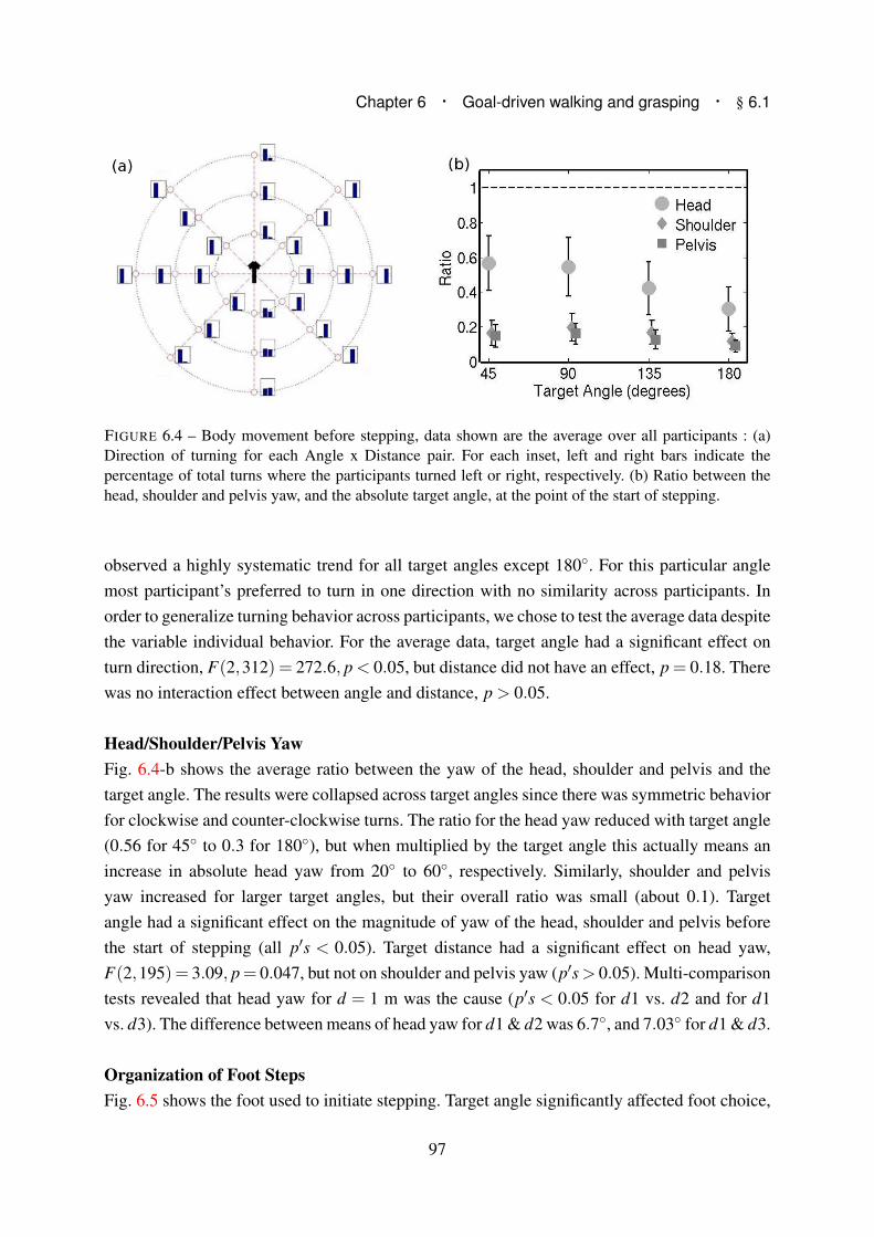
Chapter 6 · Goal-driven walking and grasping · § 6.1
FIGURE 6.4 – Body movement before stepping, data shown are the average over all participants : (a)
Direction of turning for each Angle x Distance pair. For each inset, left and right bars indicate the
percentage of total turns where the participants turned left or right, respectively. (b) Ratio between the
head, shoulder and pelvis yaw, and the absolute target angle, at the point of the start of stepping.
observed a highly systematic trend for all target angles except 180◦. For this particular angle
most participant’s preferred to turn in one direction with no similarity across participants. In
order to generalize turning behavior across participants, we chose to test the average data despite
the variable individual behavior. For the average data, target angle had a significant effect on
turn direction, F(2,312) = 272.6, p < 0.05, but distance did not have an effect, p = 0.18. There
was no interaction effect between angle and distance, p > 0.05.
Head/Shoulder/Pelvis Yaw
Fig. 6.4-b shows the average ratio between the yaw of the head, shoulder and pelvis and the
target angle. The results were collapsed across target angles since there was symmetric behavior
for clockwise and counter-clockwise turns. The ratio for the head yaw reduced with target angle
(0.56 for 45◦ to 0.3 for 180◦), but when multiplied by the target angle this actually means an
increase in absolute head yaw from 20◦ to 60◦, respectively. Similarly, shoulder and pelvis
yaw increased for larger target angles, but their overall ratio was small (about 0.1). Target
angle had a significant effect on the magnitude of yaw of the head, shoulder and pelvis before
the start of stepping (all p′s < 0.05). Target distance had a significant effect on head yaw,
F(2,195) = 3.09, p= 0.047, but not on shoulder and pelvis yaw (p′s> 0.05). Multi-comparison
tests revealed that head yaw for d = 1 m was the cause (p′s < 0.05 for d1 vs. d2 and for d1
vs. d3). The difference between means of head yaw for d1 & d2 was 6.7◦, and 7.03◦ for d1 & d3.
Organization of Foot Steps
Fig. 6.5 shows the foot used to initiate stepping. Target angle significantly affected foot choice,
97
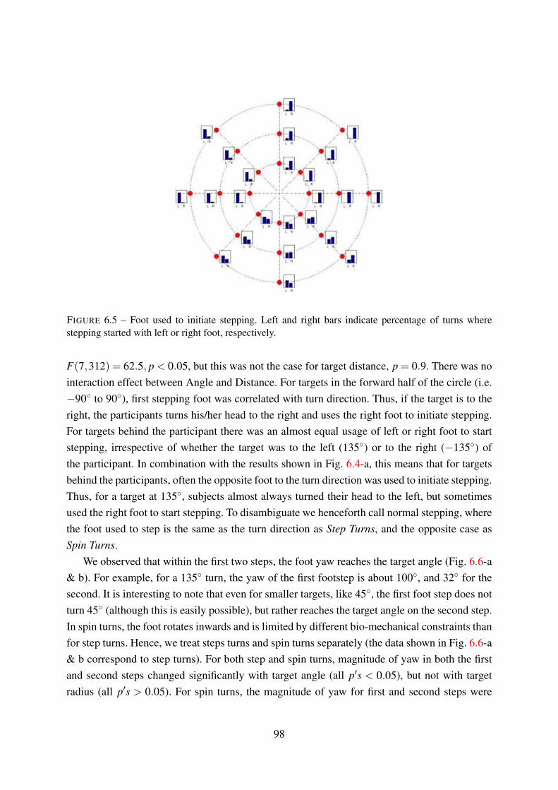
FIGURE 6.5 – Foot used to initiate stepping. Left and right bars indicate percentage of turns where
stepping started with left or right foot, respectively.
F(7,312) = 62.5, p < 0.05, but this was not the case for target distance, p = 0.9. There was no
interaction effect between Angle and Distance. For targets in the forward half of the circle (i.e.
−90◦ to 90◦), first stepping foot was correlated with turn direction. Thus, if the target is to the
right, the participants turns his/her head to the right and uses the right foot to initiate stepping.
For targets behind the participant there was an almost equal usage of left or right foot to start
stepping, irrespective of whether the target was to the left (135◦) or to the right (−135◦) of
the participant. In combination with the results shown in Fig. 6.4-a, this means that for targets
behind the participants, often the opposite foot to the turn direction was used to initiate stepping.
Thus, for a target at 135◦, subjects almost always turned their head to the left, but sometimes
used the right foot to start stepping. To disambiguate we henceforth call normal stepping, where
the foot used to step is the same as the turn direction as Step Turns, and the opposite case as
Spin Turns.
We observed that within the first two steps, the foot yaw reaches the target angle (Fig. 6.6-a
& b). For example, for a 135◦ turn, the yaw of the first footstep is about 100◦, and 32◦ for the
second. It is interesting to note that even for smaller targets, like 45◦, the first foot step does not
turn 45◦ (although this is easily possible), but rather reaches the target angle on the second step.
In spin turns, the foot rotates inwards and is limited by different bio-mechanical constraints than
for step turns. Hence, we treat steps turns and spin turns separately (the data shown in Fig. 6.6-a
& b correspond to step turns). For both step and spin turns, magnitude of yaw in both the first
and second steps changed significantly with target angle (all p′s < 0.05), but not with target
radius (all p′s > 0.05). For spin turns, the magnitude of yaw for first and second steps were
98

Chapter 6 · Goal-driven walking and grasping · § 6.2
FIGURE 6.6 – (a) Yaw angle of first step with respect to the target angle. The three lines correspond to
targets at 1, 2 and 3 m distance.(b) Yaw angle of second step (relative to yaw of first step) with respect to
the target angle.
different than that for step turns (not shown), but the final foot yaw after two steps still reached
the target angle.
Fig. 6.7-a shows the change in the size of the first step based on target angle and distance.
Analysis showed that both target angle and target distance had a significant effect on step size,
and there was also an interaction effect between the Angle and Distance (all p′s < 0.05). We
note that for all target distances, step size decreased for larger target angles. Since step yaw
increased for larger target angles, we present the step size as a function of step yaw (Fig. 6.7-b).
Linear regression analysis confirmed that step size significantly decreased as step yaw increased
(t(648) =−19.33, p< 0.001). Upon reaching the target angle, the subsequent steps (if required)
were at close to maximum step size (about 0.7 m on average). We observed that often the final
step was shorter, possibly to bring the person within comfortable grasping range.
Organization of Grasping
Most participants preferred to grasp with the right hand (they were all right-handed). The time
and distance of the maximum velocity of grasping hand did not show any stereotypical behavior.
However, we observed that the grasping motion smoothly followed the hand swing.
6.2 Synthesis of human movement invariants as rules
The results from the observation of human behavior during a walking and grasping task allows
us to extract some behavioral “invariants”. We can enumerate the general organization of
movement in the following rules :
99

FIGURE 6.7 – (a) Variation of step size as a function of target angle and distance (b) Linear regression of
step size vs. step yaw. Dots indicate the assimilated data points across all participants that were used in
the regression.
• Based on a target at a known angle relative to the person, a turn direction is chosen. If the
target is directly behind, this choice is dependent on the individual, with most having a
preferred turning direction.
• Before starting to step we rotate the head, shoulder and pelvis in the direction of the
target. The magnitude of the head yaw depends on the angle of the target. The shoulder
and pelvis also contribute to the overall yaw, but to a much lesser degree than the head.
• The choice of foot to start stepping depends on the target angle. For targets in the front
of us, we usually start with the left or right leg, if the target is to the left or right,
respectively. For targets behind us, we often first step inwards with the leg opposite to
the turn direction.
• The first two foot steps are organized such that the orientation of the second step is close
to the target angle required to reach. The organization of step turns is different from that
for spin turns. Step size decreases with increasing step yaw.
• The hand grasp motion starts smoothly during the final hand swing and before the end of
stepping.
6.3 Generalizing results to other anthropomorphic figures
In order to reproduce behavior similar to humans, the results detailed in the previous section
need to be generalized to other anthropomorphic figures. Additionally, we would like to generate
the key characteristics for targets at intermediate Distances and Angles. Fig. 6.8 shows the
general scheme of the implementation. In this section we first detail the interpolation of the
100

Chapter 6 · Goal-driven walking and grasping · § 6.3
FIGURE 6.8 – Overall scheme used to regenerate motion parameters for other anthropomorphs. So far
we have gathered knowledge of human motion and now apply that to the motion of another, possibly
differently structured, anthropomorphic figure.
human results that approximates behavior for Angles and Distances that were not in the original
protocol. Second, we normalize the results in order to scale them onto anthropomorphs of
different size and limitations than an average human.
Generalizing to all targets
Decisional parameters, like turn direction, were recorded as probabilities based on a given target
angle. We assume the behavior at intermediate target angles to be continuous and approximate
this by interpolating the recorded data points. Fig. 6.9 shows this interpolation for the turn
direction parameter. Similarly, the other parameters were interpolated with respect to target
angle. The only exception was step size, which was modeled with respect to step yaw and
was calculated using the slope of the regression line in Fig. 6.7-b. Interpolations were done
using a special symmetric FIR filter that allows the original data to pass through unchanged and
interpolates between so that the mean-square errors between the interpolated points and their
ideal values are minimized [MatlabFIR 1979].
Normalizing human results
In order to normalize the results of our human experiments we first need to know the maximum
limits of the human body. This is of course not easy to measure as each individual is essentially
different, and the measuring process cumbersome. In the field of computer animation, studies
101

have developed ways to transfer human motion to anthropomorphic figures by normalizing the
motion [Boulic et al. 2009]. A similar normalization was also applied while imitation human
movements on the humanoid in Chapter 3. We take inspiration from these sources to define
the maximum limits of an average human. Limit for head yaw was set as 90◦, and maximum
shoulder and pelvis yaw were both set as 45◦. Step size was normalized against a maximum
value of 0.8 m, similarly, maximum yaw for a step turn as 135◦ and maximum yaw for a spin
turn was 60◦.
FIGURE 6.9 – Probability of turning towards the right given a target angle. Intermediate probabilities
were calculated using an interpolation filter.
Regenerating motion invariants
Here, we use the generalized and normalized results to regenerate the key motion parameters
for an anthropomorph. The inputs to the algorithm are the target angle, θtarg, and distance,
dtarg, relative to the anthropomorph. Fig. 6.8 shows the general architecture of the algorithm.
Additionally, we have to take into account the limitations of the anthropomorph. For the
parameters calculated we need to define the following limits :
[
θm hd θm sh θm pl θm st θm sp Lm st Lgp
]
(6.1)
where, θm hd , θm sh and θm pl , are the maximum permissible yaw of the head, shoulder and
pelvis. θm st and θm sp are the maximum possible outward and inward yaw of the feet,
respectively. Lm st is the maximum step size possible, and Lgp is the grasping range of the
anthropomorph.
First, given a target angle and using the probability distributions described in the previous
section, we predict the turning direction as turnDir = p(θtarg). p is the probability distribution
of turning right as a function of angle. For, θtarg = 180◦, we use the results of the average data
across participants rather than setting a preferred turning direction, since, unlike humans, an
anthropomorphic figure is symmetrical and the ’costs’ of turning left or right in this case are
102

Chapter 6 · Goal-driven walking and grasping · § 6.3
equal. Second, we take into account the joint limits of the anthropomorph to calculate the head,
shoulder and pelvis yaw before stepping :
θhd
θsh
θpl
=
αhd(θtarg)θm hd
αsh(θtarg)θm sh
αpl(θtarg)θm pl
(6.2)
where, αhd(θtarg), αsh(θtarg) and αpl(θtarg) are the normalized scale factors determined from
the human experiments for a given θtarg.
Similar to turn direction, we choose the stepping foot using the results in Fig. 6.5 & 6.6.
Steps were organized in three phases, the Orientation Phase (OP) which contributes to a major
part of the orientation change towards the target, the Translation Phase (TP) that moves the
body towards the target, and a final Grasping Phase (GP) that adjusts the distance from target
in order to be at a comfortable grasping distance. For each phase we calculated the number of
steps required based on the step yaw, spin yaw and step size limitations. For the orientation
phase, number of steps nOP (rounded to the next integer) is :
nOP = int(θtarg/(θm st +θm sp))+1
where, int(..) is the integer-part function. Step yaw and step size for the stepping foot were
calculated relative to the support foot. Iteratively for each step i = 1, ...,nOP,
θi =
{
αst(θtarg)θm st for step turns
αsp(θtarg)θm sp for spin turns
Li = αst size(θtarg)Lm st
where, θi is the yaw for the current step i. αst and αsp are the normalized scale factors for
step and spin turns calculated from human motion. αst size is the scale factor derived from the
normalized value of the regression results shown in Fig. 6.7-b.
Fig. 6.10 shows the organization of the first two steps for a target at 130◦ and a distance
of 1.7 m. The first step is a step turn, i.e. turn direction is to the left and the left foot initiates
stepping. The next step is a spin turn since the foot rotates inwards and so on.
At the end of the orientation phase there is usually a small difference between the target
angle and the cumulative yaw angle of the leading foot ∑nop
i=1 θi (due to the scale factor not
allowing steps at maximum yaw). This difference, θtarg −∑nop
i=1 θi, is covered equally during the
steps in the translation phase. The number of steps in the translation phase are calculated from
the distance to target as,
103

FIGURE 6.10 – Organization of first two steps for θtarg = 130◦ and dtarg = 1.7 m, starting from half-sitting
configuration. Figure not to scale.
nT P = int((dtarg −dOP −Lgp)/Lm st)+1
where, dOP is the distance towards the target already covered in the orientation phase. Relative
step size and yaw were calculated as in the previous phase. For the grasp phase (GP) the final
step size is adjusted such that the final stepping foot is 0.1 m inside the grasping range (if it is
not already within the grasping range). Fig. 6.11 shows an example output of the algorithm for
a target at 130◦ and 1.7 m distance.
6.4 HRP-2 Experiments
The results of the algorithm are presented on the humanoid robot HRP-2. The parameters
generated by our algorithm were applied as kinematic tasks and whole-body motion of the
humanoid was generated using a task based prioritized inverse kinematics solver. Dynamic
stability of the humanoid during stepping was considered using the Zero Moment Point (ZMP)
formulation [Kajita et al. 2003; Vukobratovic and Stepanenko 1972]. Both of these topics were
explained in Chapter 2, in §2.2.2 & §2.3. The overall motion of the humanoid was generated
using an implementation of these principles in a package developed in a previous study [Yoshida
et al. 2006; Kanoun 2009] (see §2.4 for more details).
104

Chapter 6 · Goal-driven walking and grasping · § 6.4
FIGURE 6.11 – Organization of Steps : Sample output of the algorithm for θtarg = 130◦ and dtarg = 1.7 m.
Step positions and orientations are defined in the local right-handed coordinate system centered on the
support foot, i.e. right foot for left footsteps and vice versa. The limitations used to generate these values
correspond to the humanoid robot HRP-2.
Whole-body motion generation
For HRP-2, the limitations defined in Eqn. (6.1) were : [90◦, 45◦, 45◦, 45◦, 30◦, 0.23 m,
0.5 m]. To implement the output of the algorithm in Section 6.3 we defined the following
tasks/constraints :
1. Constraint to maintain waist Z-height (t = 0 to Tend) [2]
2. Constraint to maintain waist vertical (t = 0 to Tend) [2]
3. Constraint to maintain chest vertical (t = 0 to Tend) [2]
4. Head, Chest and Waist rotation task (t = 0 to Tgaze) [3]
5. Steps built from algorithm output (t = 0 to TstepEnd) [1]
with nsteps = nOP +nT P +nGP
6. Head rotation task to fixate on the target (t = Tgaze to Tend) [3]
7. Grasping task (t = Tgrasp to Tend) [2]
The tasks and constraints are presented in the chronological order of their starting time,
and not in the order of their priority. The priority level for each task is indicated in the square
brackets at the end. Priority level [1] is the highest and normally reserved for tasks dealing with
stability. In this case this was the sequence of steps.
Tgaze was the time allotted to rotate the head, chest and waist of HRP-2 to the values
calculated by Eqn. (6.2), and was set as 1 second. The grasp hand was chosen depending on
the hand swing during walking. HRP-2’s hands were controlled to swing in counter-phase to
the stepping, and the hand which was in the down-swing phase at the time of final step was
chosen for grasping, such that the overall motion of the grasping hand was smooth. By building
105
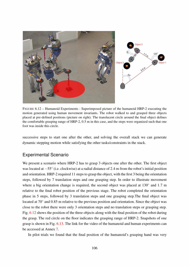
FIGURE 6.12 – Humanoid Experiments : Superimposed picture of the humanoid HRP-2 executing the
motion generated using human movement invariants. The robot walked to and grasped three objects
placed at pre-defined positions (picture on right). The translucent circle around the final object defines
the comfortable grasping range of HRP-2, 0.5 m in this case, and the steps were organized such that one
foot was inside this circle.
successive steps to start one after the other, and solving the overall stack we can generate
dynamic stepping motion while satisfying the other tasks/constraints in the stack.
Experimental Scenario
We present a scenario where HRP-2 has to grasp 3 objects one after the other. The first object
was located at −55◦ (i.e. clockwise) at a radial distance of 2.4 m from the robot’s initial position
and orientation. HRP-2 required 11 steps to grasp the object, with the first 3 being the orientation
steps, followed by 7 translation steps and one grasping step. In order to illustrate movement
where a big orientation change is required, the second object was placed at 130◦ and 1.7 m
relative to the final robot position of the previous stage. The robot completed the orientation
phase in 5 steps, followed by 3 translation steps and one grasping step.The final object was
located at 70◦ and 0.85 m relative to the previous position and orientation. Since the object was
close to the robot there were only 3 orientation steps and no translation steps or grasping step.
Fig. 6.12 shows the position of the three objects along with the final position of the robot during
the grasp. The red circle on the floor indicates the grasping range of HRP-2. Snapshots of one
grasp is shown in Fig. 6.13. The link for the video of the humanoid and human experiments can
be accessed at Annex 7.
In pilot trials we found that the final position of the humanoid’s grasping hand was very
106

Chapter 6 · Goal-driven walking and grasping · § 6.5
FIGURE 6.13 – Humanoid Experiments : Snapshots of the humanoid as it turned and grasped object 2
(130◦ & 1.7 m).
close to that used in the algorithm (mean error about 5 cm). However, grasping requires precise
control of the hand and even small differences at the beginning of the motion (for example,
due to slipping of the robot’s feet on the ground) can cause errors that make the final grasp
inaccurate. To solve this problem, we deliberately stop the grasping motion a little before the
actual target. The final grasp is executed by using HRP-2’s cameras which localize the object
(an orange ball) in 3D and then automatically execute a precise grasping motion (see [Yoshida
et al. 2007] for more details).
6.5 Discussion
The approach presented in this Chapter shows how anthropomorphic motion can be generated
by using key information from the study of human movements. The idea of ’realism’ of
anthropomorphic motion is qualitative and hence difficult to prove mathematically. While
imitating human movements in Chapter 3, we developed a metric to quantify the goodness
of imitation by looking at the error between the joint angles (or positions) of the human and
the figure being controlled. Similar ways to validate the effectiveness of other approaches have
been used elsewhere ([Dariush et al. 2008]).
However, these parameters are often task-specific and cannot be compared across studies.
Instead, we qualify our results by noting the following points. First, the humanoid HRP-2
walked to, and grasped, objects in the physical space having the same dimensions as the humans.
Although the yaw of HRP-2’s head, chest etc. were different from the humans, they were
organized in the same way. The humanoid needed more steps to turn and walk than humans, but
again the organization of these steps followed the same rules as in humans.
The results from our human walking experiments could also serve as a valuable knowledge
base for guiding pure robotics based local optimization techniques like [Kanoun 2009]. The
107

drawback of using local optimization to generate motion for redundant anthropomorphic figures
is that in certain cases it may reach the final goal, but in a manner completely different from that
expected in humans, or fail altogether. By adding information from human movements these
methods could be made more robust and the motion more realistic.
At a more general level, the results from these experiments illustrates the link between
perception (or goal) and its effect on movements being generated. For example, the fact that we
see similar results across all our subjects tells us that the first two steps, or rather the organization
of the beginning of such movements, is highly dependent on the goal. In the previous chapter
this initial movement was driven by an instantaneous input from the user. In the current scenario
the statistics and invariants extracted from stepping tell us about how it is important to first orient
oneself towards the goal before planning motion to walk towards it. It is important to note that
these results tell us about the general organization of human-like movements given a goal. This
problem is different from that dealt with in studies on humanoid navigation (e.g. [Chestnutt
et al. 2007]). However, reactive navigation in humanoid robots can be thought of as continually
updating short-term goals and in this context it could be interesting to add information from
similar navigation strategies in humans.
In this study the walking was driven by a grasping task. It is important to note that the
rules derived here as essentially independent of this grasping task. We could replace the final
grasp with any other task that requires a focused visual attention. Related to the issue of visual
attention, is the assumption we made that the head is driven by the gaze. Recording gaze during
locomotion in humans is cumbersome, and most humanoids do not have vision independent
of the head direction. For these reasons we limit our formulation to the orientation of the head,
and base our assumption of synergistic eye-head movements on neuroscience results [Imai et al.
2001].
108
7Conclusions
TO conclude the work conducted in this thesis, we structure our final arguments into three
sections, the general contributions, the applicability of ideas developed in this thesis, and
its limitations and some perspectives for future work.
General contributions
To illustrate the general problem addressed by this thesis and its contribution we refer to
the two figures Fig. 7.1 & Fig. 7.2. In Fig. 7.1 the task given the humanoid robot was to
grasp an object beyond its immediate reach, i.e. it was required to make steps to achieve
this goal. The top panels in this figure show the generated motion using a state-of-the-art
motion planning algorithm ([Kanoun et al. 2010]), that addresses the planning of footsteps
as a problem of inverse kinematics by just specifying the final goal. It is important to note
that the approach developed in that study required only the definition of one single task (grasp
object at goal(x,y,z)) and the entire whole-body motion including dynamic stepping behavior
was generated automatically. Also important is that there was no need to incorporate any ideas
or motion biases from human movements to arrive at this solution, i.e. this is a pure robotics
solution.
In contrast, we now refer to the bottom panels in Fig. 7.1. Using exactly the same framework
109

FIGURE 7.1 – Why consider human movements to plan humanoid motion - I ? Top panel : HRP-2 walks
to and grasps an object 2 m in front. The entire motion including dynamic stepping was generated
automatically using the approach in [Kanoun et al. 2010]. Bottom panel : When the same framework
is used to grasp an object directly behind, the resulting motion (while valid) is not at all human-like.
we now place the goal directly behind the robot and notice that the results are less attractive
than in the previous case. Instead of turning around and grasping the object, the robot walked
backwards and ended up in a strange posture. From a pure robotics perspective, the solution is
still valid (i.e. the task was completed) but the result is unsatisfactory if one were to demand
human-like behavior from humanoid robots. This difference in the two solutions, illustrates
the limitations of motion planning based on local optimization. Since the only cost taken into
account is the quickest resolution of the task, the walking-backwards motion in the bottom
panels are much easier for HRP-2 than turning around and walking while facing the goal.
With this problem in mind we now shift focus to the snapshots shown in Fig. 7.2. This
figure shows the walking and grasping motion as generated by the approach in the final Chapter
6. Instead of walking backwards, or sideways, the humanoid robot smoothly turns towards its
goal and walks towards it to make the final grasp. Here, by studying human movements and
developing a model of their organization, we use the same local optimization tools to generate
motion that is realistic and completes the grasp task is a sensible manner. It is important to note
that these are results not directly obvious from a pure motion planning perspective, but rather a
consequence of a perceptual requirement.
The contrasting results between Fig. 7.1 and Fig. 7.2 highlight the niche that the work
in this thesis fits into. While the problem of motion planning for humanoids, is a robotics
problem, the general contribution of this thesis is in showing that the complete solution lies
110

Chapter 7 · Conclusions · § 7.0
FIGURE 7.2 – Why consider human movements to plan humanoid motion - II ? By studying the
organization of human movements, local optimization methods can be guided to a more human-like
result. The results from this thesis illustrate some constructive ways to integrate methods from human
neuroscience into humanoid robotics.
in the convergence of methods from robotics and human neuroscience.
Application
For a researcher working in life sciences, a fundamental motivation is curiosity about nature
and its biological mechanisms. In robotics, there is the additional aspect of practical application
on robots in real-life situations. With regard to inter-disciplinary theses like this one, it is
therefore important to comment on the usefulness of the methods and principles developed.
While a neuroscientist reading this document might find the cross-application of methodologies
interesting, a roboticist might be left with the question ; how does investing effort in formally
studying humans, improve or assist established methods in humanoid robotics ?
To answer this question we first take the example of the study in Chapter 4. To make HRP-2
play the yoyo we started by first analyzing human yoyo playing. Critically speaking, it may
have been possible to make the humanoid robot play the yoyo without considering the human
data. Possibly by a double optimization, where unknown model parameters are optimized until
the stability constraints were satisfied. However, we believe that by starting from a human
perspective we not only significantly simplified the problem, but also improved the accuracy of
the final result. As an added bonus, the analysis of human yoyo playing using classical robotics
tools like optimal control, could also provide insights into human sensorimotor control. The first
steps in this regard can be seen in [Mombaur and Sreenivasa 2010b]. This fundamental idea of
using human movements to simplify problems in humanoid robotics can be extended to other
scenarios (like for example that in §3.3), and provides an interesting alternative to pure robotics
approaches.
While using local optimization techniques to plan motion for redundant systems like
humanoid robots, one has to deal with problems of local minima (see for example [Kanoun
2009]). Probabilistic methods like RRT/PRM can be used to complement local planners by
111

providing a global strategy [Dalibard et al. 2009; Berenson et al. 2009; Stilman 2010]. However,
there is still no guarantee that the final solution found, and the planned motion, are human-like.
This is hardly a concern for an industrial manipulator, but for a humanoid robot intended to
work among humans, this is (or rather will be) a real problem. In Chapter 6 we presented
an alternative way to find such a global strategy for that task. By deriving the rules from the
systematic study of humans, we ensure that the humanoid motion derived via local optimization
is realistic. We believe that the idea of using human movement invariants and expressing them
as kinematic tasks could prove to be an interesting source of inspiration for motion planning
algorithms.
Related to the motion planning aspect, is the issue of realism of humanoid robot motion.
We covered this topic with some supporting arguments in the introduction to this thesis (§1.1).
The notion of realistic robotic motion is difficult to quantify. Often, the answer to the question,
“Does the robot move/behave/act like a human ?”, is subjective to the observer. In the case of
the experiments of this thesis, we could say that the walking motion in Chapter 6 was a lot more
realistic than in Chapter 5. But such an abstract sense of realism is of little use within a practical
robotics setting. As an alternative metric, maybe a better way to qualify the realism of a method
is to look at the practical capability that it imparts to the humanoid robot. By teaching HRP-2
to play the yoyo, we gave it a fun and dynamic skill, but from our arguments it is clear that this
was also a challenging task. By providing a general set of rules to walk and grasp an object, we
extended the robot’s manipulable space while preserving the human likeness. Judging by these
results, and our metric, we believe that our results are indeed realistic.
Limitations and future perspectives
The models developed in this work mostly deal with the kinematic characteristics of human
movement and humanoid motion. In order to consider humanoid dynamic stability we used
the simplified ZMP formulation. For the scenarios chosen in this work, this criterion proved to
be sufficient. However, as we move towards more dynamic movements (like for example the
tight-rope walker in §1.3), it might become necessary to involve dynamics in both the modeling
as well as humanoid motion planning stages. Unified frameworks for kinematic and dynamic
motion planning integrating works like [Nakamura and Yamane 2000], [Khatib et al. 2004],
[Featherstone 2007] and [Nakanishi et al. 2008] might provide interesting extensions for further
application of human movement models during highly dynamic activities.
Generalization of results like that in Chapter 6 to all, or a wide range of, human tasks is
a big challenge. We believe that goal-directed locomotion is an important task for humans as
well as humanoids. Subsequently, we modeled this with a grasp task at the end. However, the
rules extracted from our experiments are specific to these tasks. In the interest of extending
112

Chapter 7 · Conclusions · § 7.0
such gait planning methods to a wider range of tasks, it would be advantageous to develop a
more general framework of rules, possibly by automating the process to go from movement
invariants to kinematic tasks. Possible steps in this regard could be automatic segmentation
of human behaviors using approaches like [Kulic et al. 2009; Lee and Nakamura 2010]. The
invariants of this segmented information could then be automatically extracted using statistical
tools like those used in this thesis. State of the art motion planning algorithms like [Kanoun
2009] could then be used to animate the anthropomorph without the need for specific heuristics.
Such aspects of automatic humanoid gait planning, following from the systematic study of
humans, will be the focus of future work.
113

References
ALEXANDROV, A., FROLOV, A., AND MASSION, J. 1998. Axial synergies during human
upper trunk bending. Experimental Brain Research 118, 210–220. 40, 41
ANDRIACCHI, T. AND ALEXANDER, E. 2000. Studies of human locomotion : past, present
and future. Journal of Biomechanics 33, 1217–24. 71
BATZ, G., SOBOTKA, M., WOLLHERR, D., AND BUSS, M. 2009. Robot basketball : Ball
dribbling - a modified task. In Proceedings of German Workshop on Robotics. 47
BEAL, D. AND SACHINIS, M. Robotuna 2. http ://web.mit.edu/towtank/www/Tuna/tuna.
html. 8
BEAR, M. F., CONNORS, B. W., AND PARADISO, M. A. 2006. Neuroscience : Exploring
the Brain. Lippincott Williams & Wilkins. 7
BENNEQUIN, D., FUCHS, R., BERTHOZ, A., AND FLASH, T. 2009. Movement timing and
invariance arise from several geometries. PLoS Computational Biology. 7
BERENSON, D., CHESTNUTT, J., SRINIVASA, S., KUFFNER, J., AND KAGAMI, S. 2009.
Pose-constrained whole-body planning using task space region chains. In IEEE-RAS
International Conference on Humanoid Robots. 181 –187. 28, 109
BERTHOZ, A. 2000. The brain’s sense of movement. Harvard University Press, Cambridge,
MA. 74
BERTHOZ, A. 2009. La simplexite. Odile Jacob, Paris. 7
BITZER, S. AND VIJAYAKUMAR, S. 2009. Latent spaces for dynamic movement primitives.
IEEE-RAS International Conference on Humanoid Robots. 12, 45
BOCK, H. AND PLITT, K. 1984. A multiple shooting algorithm for direct solution of optimal
control problems. In Proceedings of the 9th IFAC World Congress, Budapest. 242–247. 58
BOULIC, R., MAGNENAT-THALMANN, N., AND THALMANN, D. 1990. A global human
walking model with real-time kinematic personification. Visual Computer 6, 6, 344–358. 72,
89
BOULIC, R., MAUPU, D., AND THALMANN, D. 2009. On scaling strategies for the full
body interaction with virtual mannequins. Journal Interacting with Computers, Special Issue
on Enactive Interfaces 21, 1-2, 11–25. 37, 100
BOULLION, T. AND ODELL, P. 1971. New York : Wiley Interscience. 20
115
BUEHLER, M. AND KODITCHEK, D. 1990. From stable to chaotic juggling : theory,
simulations and experiments. In IEEE International Conference on Robotics and Automation.
1976–1981. 47
CHESTNUTT, J., MICHEL, P., KUFFNER, J., AND KANADE, T. 2007. Locomotion among
dynamic obstacles for the honda asimo. IEEE/RSJ International Conference on Intelligent
Robots and Systems. 86, 106
COURTINE, G. AND SCHIEPPATI, M. 2003. Human walking along a curved path. i. body
trajectory, segment orientation and the effect of vision. European Journal of Neuroscience 18,
177–190. 8
CRAIG, J. J. 2005. Introduction to robotics : Mechanics and control. Pearson Prentice Hall.
28
DALIBARD, S., NAKHAEI, A., LAMIRAUX, F., AND LAUMOND, J.-P. 2009. Whole-body
task planning for a humanoid robot : a way to integrate collision avoidance. In IEEE-RAS
International Conference on Humanoid Robots. 355 –360. 28, 109
DARIO, P., LASCHI, C., MENCIASSI, A., GUGLIELMELLI, E., CARROZZA, A., AND
MICERA, S. 2003. Interfacing neural and artificial systems : from neuroengineering to
neurorobotics. In Neural Engineering, 2003. Conference Proceedings. First International
IEEE EMBS Conference on. 418 – 421. 13
DARIUSH, B., GIENGER, M., ARUMBAKKAM, A., GOERICK, C., ZHU, Y., AND
FUJIMURA, K. 2008. Online and markerless motion retargeting with kinematic constraints.
In IEEE/RSJ International Conference on Intelligent Robots and Systems. 191–198. 11, 34,
37, 44, 105
DARIUSH, B., GIENGER, M., JIAN, B., GOERICK, C., AND FUJIMURA, K. 2008. Whole
body humanoid control from human motion descriptors. In IEEE International Conference
on Robotics and Automation. 2677–2684. 91
DAY, B., CAUQUIL, A. S., BARTOLOMEI, L., PASTOR, M. A., AND LYON, I. N. 1997.
Human body-segment tilts induced by galvanic stimulation : a vestibularly driven balance
protection mechanism. Journal of Physiology 500, 3, 661–672. 72
DAY, B. L. AND FITZPATRICK, R. C. 2005. The vestibular system. Current Biology 15, 15,
R583–R586. 71
DINGWELL, J., CUSUMANO, J., CAVANAGH, P., AND STERNAD, D. 2001. Local dynamic
stability versus kinematic variability of continuous overground and treadmill walking.
Journal of Biomechanics 123, 27–32. 71
ERNST, M. O. AND BULTHOFF, H. H. 2004. Merging the senses into a robust percept.
TRENDS in Cognitive Sciences 8, 4, 162–169. 7
FEATHERSTONE, R. 2007. Rigid body dynamics algorithms. Springer. 110, 129
FLANDERS, M., DAGHESTANI, L., AND BERTHOZ, A. 1999. Reaching beyond reach.
Experimental Brain Research 126, 19–30. 73
116
Chapter 7 · Conclusions · § 7.0
FLASH, T. AND HOCHNER, B. 2005. Motor primitives in vertebrates and invertebrates.
Current Opinion in Neurobiology 15, 660–666. 42
FLASH, T. AND HOGAN, N. 1985. The coordination of arm movements : An experimentally
confirmed mathematical model. Journal of Neuroscience 5, 1688–1703. 12
FLEURY, S., HERRB, M., AND CHATILA, R. 1997. Genom : A tool for the specification
and the implementation of operating modules in a distributed robot architecture. In IEEE/RSJ
International Conference on Intelligent Robots and Systems. 842–848. 28
GALATI, G., PELLE, G., BERTHOZ, A., AND COMMITTERI, G. 2010. Multiple reference
frames used by the human brain for spatial perception and memory. Experimental Brain
Research. 5
GESCHEIDER, G. 1997. Psychophysics, The Fundamentals. Lawrence Ehrlbaum
Associates, Mahwah, New Jersey. 7
GRASSO, R., PREVOST, P., IVANENKO, Y., AND BERTHOZ, A. 1998. Eye-head
coordination for the steering of locomotion in humans : an anticipatory synergy. Neuroscience
Letters 253, 115–118. 8, 74
GUIGON, E., BARADUC, P., AND DESMURGET, M. 2007. Computational motor control :
Redundancy and invariance. Journal of Neurophysiology 97, 331–347. 12
HAITH, A., JACKSON, C., MIALL, C., AND VIJAYAKUMAR, S. 2008. Unifying the
sensory and motor components of sensorimotor adaptation. In Neural Information Processing
Systems. 7
HARADA, K., MIURA, K., MORISAWA, M., KANEKO, K., NAKAOKA, S., KANEHIRO,
F., TSUJI, T., AND KAJITA, S. 2009. Toward human-like walking pattern generator.
In IEEE/RSJ international conference on Intelligent robots and systems. IEEE Press,
Piscataway, NJ, USA, 1071–1077. 12, 72, 89
HARRIS, C. AND WOLPERT, D. 1998. Signal-dependent noise determines motor planning.
Nature 394, 725–6. 12
HARTCHER-O’BRIEN, J., LUCA, M. D., AND ERNST, M. 2010. Audiovisual integration :
the duration of uncertain times. Journal of Vision (accepted). 7
HASHIMOTO, K. AND NORITSUGU, T. 1996. Modeling and control of robot yoyo with
visual feedback. In IEEE International Conference on Robotics and Automation. 2650–2655.
48
HAUSER, H., NEUMANN, G., IJSPEERT, A., AND MAASS, W. 2007. Biologically inspired
kinematic synergies provide a new paradigm for balance control of humanoid robots. IEEE-
RAS International Conference Humanoids. 12
HAYWARD, V. 1993. Borrowing some design ideas from biological manipulators to design
an artificial one. In Robots and Biological Systems, NATO Series, 135–148. 8
HAYWARD, V. 2009. Motion aftereffects transfer between touch and vision. Current
Biology 19, 9, 745–50. 7
117

HICHEUR, H., PHAM, Q., ARECHAVALETA, G., LAUMOND, J., AND BERTHOZ, A. 2007.
The formation of trajectories during goal-oriented locomotion in humans i. a stereotyped
behavior. European Journal of Neuroscience 26, 2346–2390. 8, 71
HICHEUR, H., VIEILLEDENT, S., AND BERTHOZ, A. 2005. Head motion in humans
alternating between straight and curved walking path : combination of stabilizing and
anticipatory orienting mechanisms. Neuroscience Letters 383, 87–92. 8, 74, 89, 91
HIRUKAWA, H., HATTORI, S., HARADA, K., KAJITA, S., KANEKO, K., KANEHIRO, F.,
FUJIWARA, K., AND MORISAWA, M. 2006. A universal stability criterion of the foot contact
of legged robots - adios zmp. In IEEE International Conference on Robotics and Automation.
29
HOFF, B. AND ARBIB, M.-A. 1993. Models of trajectory formation and temporal
interaction of reach and grasp. Journal of Motor Behavior 25, 3, 175–192. 76
HOFFMANN, H., PASTOR, P., PARK, D.-H., AND SCHAAL, S. 2009. Biologically-inspired
dynamical systems for movement generation : automatic real-time goal adaptation and
obstacle avoidance. IEEE International Conference on Robotics and Automation. 45
HOLLANDS, M., SORENSEN, K., AND PATLA, A. 2001. Effects of head immobilization on
the coordination and control of head and body reorientation and translation during steering.
Experimental Brain Research 140, 223–233. 8, 74
IJSPEERT, A., CRESPI, A., AND CABELGUEN, J. 2005. Simulation and robotics studies of
salamander locomotion. Applying neurobiological principles to the control of locomotion in
robots. Neuroinformatics 3, 3, 171–196. 8
IMAI, T., MOORE, S., RAPHAN, T., AND COHEN, B. 2001. Interaction of the body, head
and eyes during walking and turning. Experimental Brain Research 136, 1–18. 8, 74, 89, 91,
106
INAMURA, T., TOSHIMA, I., TANIE, H., AND NAKAMURA, Y. 2004. Embodied symbol
emergence based on mimesis theory. International Journal of Robotics Research 23, 4-5,
363–377. 13
JIAN, Y., WINTER, D., ISHAC, M., AND GILCHRIST, L. 1993. Trajectory of the body cog
and cop during initiation and termination of gait. Gait Posture 1, 9–22. 71
JIN, H. AND ZACKSENHOUSE, M. 2002. Yoyo dynamics : Sequence of collisions captured
by a restitution effect. Journal of Dynamical Systems and Control 124. 48, 53, 56, 63
JIN, H. AND ZACKSENHOUSE, M. 2004. Robotic yoyo playing with visual feedback. IEEE
Transactions of Robotics 20, 4, 736–744. 48
JOHANSSON, R., WESTLING, G., BACKSTROM, A., AND FLANAGAN, J. 2001. Eye-hand
coordination in object manipulation. Journal of Neuroscience 21, 6917–6932. 73
KAJITA, S., KANEHIRO, F., KANEKO, K., FUJIWARA, K., HARADA, K., YOKOI, K., AND
HIRUKAWA, H. 2003. Biped walking pattern generator by using preview control of zero-
moment point. In IEEE International Conference on Robotics and Automation. 1620–1626.
24, 25, 26, 28, 75, 77, 81, 83, 102, 125
118
Chapter 7 · Conclusions · § 7.0
KALMAN, R. 1960. A new approach to linear filtering and prediction problems. Transaction
of the ASME - Journal of Basic Engineering. 35, 127
KAMINSKI, T. 2007. The coupling between upper and lower extremity synergies during
whole body reaching. Gait Posture 26, 256–262. 40
KANEHIRO, F., HIRUKAWA, H., AND KAJITA, S. 2004. Openhrp : Open architecture
humanoid robotics platform. International Journal of Robotics Research. 28
KANEKO, K., KANEHIRO, F., KAJITA, S., HIRUKAWA, H., KAWASAKI, T., HIRATA, M.,
AKACHI, K., AND ISOZUMI, T. 2004. Humanoid robot hrp-2. International Conference on
Robotics and Automation. 8, 36
KANOUN, O. 2009. Task-driven motion control for humanoid robots. Ph.D. thesis, LAAS-
CNRS ; Universite de Toulouse. 2, 26, 75, 82, 83, 102, 105, 109, 110
KANOUN, O., LAMIRAUX, F., AND WIEBER, P. 2009. Prioritizing linear equality and
inequality systems : application to local motion planning for redundant robots. In IEEE
International Conference on Robotics and Automation. 28
KANOUN, O., LAUMOND, J.-P., AND YOSHIDA, E. 2010. Planning Foot Placements for a
Humanoid Robot : A Problem of Inverse Kinematics. The International Journal of Robotics
Research. 107, 108
KEHL, R. AND GOOL, L. V. 2006. Markerless tracking of complex human motions from
multiple views. Comput. Vis. Image Underst. 104, 2, 190–209. 34
KHATIB, O., SENTIS, L., PARK, J., AND WARREN, J. 2004. Whole-body dynamic behavior
and control of human-like robots. International Journal of Humanoid Robotics 1, 1, 29–43.
110
KHATIB, O., SENTIS, L., AND PARK, J.-H. 2008. A unified framework for whole-body
humanoid robot control with multiple constraints and contacts. Springer Tracts in Advanced
Robotics - STAR Series, European Robotics Symposium. 29
KULIC, D., TAKANO, W., AND NAKAMURA, Y. 2009. Online segmentation and clustering
from continuous observation of whole body motions. Robotics, IEEE Transactions on 25, 5
(oct.), 1158–1166. 110
LACQUANITI, F., GRASSO, R., AND ZAGO, M. 1999. Motor patterns in walking. News in
Physiological Sciences 14, 168–174. 40
LASCHI, C., ASUNI, G., TETI, G., CARROZZA, M., DARIO, P., GUGLIELMELLI, E., AND
JOHANSSON, R. 2006. A bio-inspired neural sensory-motor coordination scheme for robot
reaching and preshaping. In Biomedical Robotics and Biomechatronics, 2006. BioRob 2006.
The First IEEE/RAS-EMBS International Conference on. 531 –536. 12
LAVALLE, S. M. 2006. Planning Algorithms. Cambridge University Press. 28
LEE, D. AND NAKAMURA, Y. 2007. Mimesis scheme using a monocular vision system on
a humanoid. IEEE International Conference on Robotics and Automation, 2162–2168. 13
119

LEE, D. AND NAKAMURA, Y. 2010. Mimesis model from partial observations for a
humanoid robot. International Journal of Robotics Research 29, 1, 60–80. 110
LEINEWEBER, D., BAUER, I., BOCK, H., AND SCHLODER, J. 2003. An efficient multiple
shooting based reduced SQP strategy for large-scale dynamic process optimization - part I :
theoretical aspects. Comput. Chem. Engng 27, 157–166. 58
LIEGEOIS, A. 1977. Automatic supervisory control of the configurationand behavior of
multibody mechanisms. IEEE Transactions Systems, Man and Cybernetics 7, 868–871. 19
LIM, B., RA, S., AND PARK, F. 2005. Movement primitives, principal component analysis,
and the efficient generation of natural motions. IEEE International Conference on Robotics
and Automation. 12, 41
MANSARD, N. AND CHAUMETTE, F. 2007. Task sequencing for high-level sensor-based
control. IEEE Transactions on Robotics 23, 60–72. 28
MATLABFIR. 1979. Finite Impulse Respose (FIR) filter, Programs for Digital Signal
Processing, Algorithm 8.1. IEEE Press, New York. 99
MCGUIGAN, F. J. 1996. Experimental Psychology Methods of Research. Prentice Hall. 7
MENZ, H., LORD, S., AND FITZPATRICK, R. 2003. Acceleration patterns of the head and
pelvis when walking on level and irregular surfaces. Gait Posture 18, 35–46. 71
MITROVIC, D., NAGASHIMA, S., KLANKE, S., MATSUBARA, T., AND VIJAYAKUMAR,
S. 2010. Optimal feedback control for anthropomorphic manipulators. IEEE International
Conference on Robotics and Automation. 12
MIURA, K., MORISAWA, M., NAKAOKA, S., KANEHIRO, F., HARADA, K., KANEKO, K.,
AND KAJITA, S. 2009. Robot motion remix based on motion capture data towards human-
like locomotion of humanoid robots. IEEE-RAS International Conference on Humanoid
Robots. 13
MIURA, K., NAKAOKA, S., MORISAWA, M., HARADA, K., AND KAJITA, S. 2008. A
friction based twirl for biped robots. IEEE-RAS International Conference on Humanoid
Robots. 13
MOMBAUR, K. 2008. Using optimization to create self-stable human-like running.
Robotica. 12, 67
MOMBAUR, K. AND SREENIVASA, M. N. 2010a. Hrp-2 plays the yoyo : From human to
humanoid yoyo playing using optimal control. In IEEE International Conference on Robotics
and Automation. 1
MOMBAUR, K. AND SREENIVASA, M. N. 2010b. Inverse optimal control as a tool to
understand human yoyo playing. In International Conference Numerical Analysis and
Applied Mathematics. 109
MOMBAUR, K., TRUONG, A., AND LAUMOND, J.-P. 2010. From human to humanoid
locomotion - an inverse optimal control approach. Autonomous Robots 28, 369–383. 12
120

Chapter 7 · Conclusions · § 7.0
MONTECILLO-PUENTE, F.-J. 2010. Human motion imitation on humanoid robot. Ph.D.
thesis, LAAS-CNRS ; Universite de Toulouse. 1, 11, 31
MONTECILLO-PUENTE, F.-J., SREENIVASA, M. N., AND LAUMOND, J.-P. 2010. On
real-time whole-body human to humanoid motion transfer. In International Conference on
Informatics in Control, Automation and Robotics. 31, 35, 38, 39, 40, 127
MORI, M. 1970. The uncanny valley. Energy 7, 4, 33–35. 4
MORISAWA, M., HARADA, K., KAJITA, S., KANEKO, K., KANEHIRO, F., FUJIWARA,
K., NAKAOKA, S., AND HIRUKAWA, H. 2006. A biped gait planning allowing immediate
modification of foot placement. IEEE-RAS International Conference on Humanoid Robots.
86
MULTON, F., KULPA, R., AND BIDEAU, B. 2008. Mkm : A global framework for animating
humans in virtual reality applications. Presence : Teleoperation in Virtual Environments 17, 1,
17–28. 37
MUSSA-IVALDI, F. AND BIZZI, E. 2000. Motor learning through the combination of
primitives. Philosophical Transactions of the Royal Society of London 355, 1755–1769. 12
NAKAMURA, Y. 1991. Advanced Robotics : Redundancy and Optimization. Addison-
Wesley Longman Publishing, Boston. 19, 21, 28, 75, 81
NAKAMURA, Y. AND HANAFUSA, H. 1986. Inverse kinematic solutions with singularity
robustness for robot manipulator control. Journal of dynamic systems, measurement and
control 108, 3, 163 –171. 20
NAKAMURA, Y. AND YAMANE, K. 2000. Dynamics computation of structure-varying
kinematic chains and its application to human figures. IEEE Transactions on Robotics and
Automation 16, 2 (apr), 124 –134. 110
NAKANISHI, J., CORY, R., MISTRY, M., PETERS, J., AND SCHAAL, S. 2008. Operational
space control : a theoretical and emprical comparison. 6, 737–757. 110
NAKAOKA, S., NAKAZAWA, A., KANEHIRO, F., KANEKO, K., MORISAWA, M., AND
IKEUCHI, K. 2005. Task model of lower body motion for a biped humanoid robot to imitate
human dances. In IEEE/RSJ International Conference on Intelligent Robots and Systems.
3157–3162. 11
NEO, E., YOKOI, K., KAJITA, S., KANEHIRO, F., AND TANIE, K. 2005. A
switching command-based whole-body operation method for humanoid robots. IEEE/ASME
Transactions on Mechatronics 10, 546–559. 75
NEO, E., YOKOI, K., KAJITA, S., AND TANIE, K. 2007. Whole-body motion generation
integrating operator’s intention and robot’s autonomy in controlling humanoid robots. IEEE
Transactions on Robotics 23, 763–775. 75
NOBLE, J. AND PRENTICE, S. 2008. Intersegmental coordination while walking up inclined
surfaces : age and ramp angle effects. Experimental Brain Research 189, 249–55. 71
121

OLIVIER, A.-H., KULPA, R., PETTRE, J., AND CRETUAL, A. 2009. A velocity-curvature
space approach for walking motions analysis. In Lecture Notes In Computer Science,
Proceedings of the 2nd International Workshop on Motion in Games. 91
OTT, C., LEE, D., AND NAKAMURA, Y. 2008. Motion capture based human motion
recognition and imitation by direct marker control. IEEE-RAS International Conference on
Humanoid Robots. 13
PATLA, A., ADKIN, A., AND BALLARD, T. 1999. Online steering : coordination and control
of body center of mass, head and body reorientation. Experimental Brain Research 129, 4,
629–634. 8, 39, 74
PETTRE, J. AND LAUMOND, J.-P. 2006. A motion capture-based control-space approach
for walking mannequins. Computer Animation and Virtual Worlds 17, 2, 109–126. 37
POZZO, T., BERTHOZ, A., AND LEFORT, L. 1990. Head stabilisation during various
locomotor tasks in humans. i. normal subjects. Experimental Brain Research. 74
POZZO, T., LEVIK, Y., AND BERTHOZ, A. 1996. Head and trunk movements in the frontal
plane during complex dynamic equilibrium tasks in humans. Experimental Brain Research.
74
PREVOST, P., IVANENKO, Y., GRASSO, R., AND BERTHOZ, A. 2002. Spatial invariance
in anticipatory orienting behavior during human navigation. Neuroscience Letters 339, 243–
247. 74
RAIBERT, M. 2008. Bigdog, the rough-terrain quadruped robot. International Federation of
Automatic Control. 8
ROETENBERG, D., LUINGE, H., AND SLYCKE, P. Xsens mvn : Full 6dof human motion
tracking using miniature inertial sensors. http ://www.xsens.com/. 34
SANGER, T. 2000. Human arm movements described by a low-dimensional superposition
of principal components. Journal of Neuroscience 20, 1066–1072. 41
SCHAAL, S. AND ATKESON, C. 1993. Open loop stable control strategies for robot juggling.
In IEEE International Conference on Robotics and Automation. 913 – 918. 47
SCHAAL, S., PETERS, J., NAKANISHI, J., AND IJSPEERT, A. 2004. Learning movement
primitives. International Symposium on Robotics Research. 12
SCHAAL, S., VIJAYAKUMAR, S., D’SOUZA, S., IJSPEERT, A., AND NAKANISHI, J.
2001. Real-time statistical learning for robotics and human augmentation. In International
Symposium of Robotics Research (ISRR01). Springer, 117–124. 37
SHADMEHR, R. AND WISE, S. 2005. The computational neurobiology of reaching and
pointing : A foundation for motor learning. MIT Press, Cambridge MA. 27
SICILIANO, B. AND KHATIB, O. 2008. Springer handbook of robotics. Springer. 9
SICILIANO, B. AND SLOTINE, J. 1991. A general framework for managing multiple tasks
in highly redundant robotic systems. In IEEE International Conference Advanced Robotics.
1211–1216. 20, 21
122
Chapter 7 · Conclusions · § 7.0
SONYCORP. Sony aibo. http ://support.sony-europe.com/aibo/. 8
SOUMAN, J. L., FRISSEN, I., SREENIVASA, M. N., AND ERNST, M. O. 2009. Walking
straight into circles. Current Biology. 7, 8, 71
SREENIVASA, M. N., FRISSEN, I., SOUMAN, J., AND ERNST, M. 2008. Walking
along curved paths of different angles : the relationship between head and trunk turning.
Experimental Brain Research 191, 313–320. 8, 71, 74, 89, 91
STASSE, O., EVRARD, P., PERRIN, N., MANSARD, N., AND KHEDDAR, A. 2009. Fast
foot prints re-planning and motion generation during walking in physical human-humanoid
interaction. IEEE-RAS International Conference on Humanoid Robots. 86
STASSE, O., VERRELST, B., DAVISON, A., MANSARD, N., SAIDI, F., VANDERBORGHT,
B., ESTEVES, C., AND YOKOI, K. 2008. Integrating walking and vision to increase
humanoid autonomy. International Journal of Humanoid Robotics 5, 287–310. 28
STILMAN, M. 2010. Global manipulation planning in robot joint space with task constraints.
IEEE Transactions on Robotics 26, 3 (june), 576 –584. 28, 109
SULEIMAN, W., YOSHIDA, E., KANEHIRO, E., LAUMOND, J.-P., AND MONIN, A. 2008.
On human motion imitation by humanoid robot. In IEEE International Conference on
Robotics and Automation. 11, 37
TAKANO, W., YAMANE, K., AND NAKAMURA, Y. 2007. Capture database through
symbolization, recognition and generation of motion patterns. In IEEE International
Conference on Robotics and Automation. 3092–3097. 13, 89
THOMAS, J., CORCOS, D., AND HASAN, Z. 2005. Kinematic and kinetic constraints on
arm, trunk, and leg segments in target-reaching movements. Journal of Neurophysiology 93,
352–364. 40, 41
THOMAZ, A. AND BREAZEAL, C. 2010. Understanding human teaching behavior to build
more effective robot learners. Artificial Intelligence Journal. 13
TODOROV, E. AND GHAHRAMANI, Z. 2003. Unsupervised learning of sensory-motor
primitives. IEEE Engineering in Medicine and Biology Society. 12
TODOROV, E. AND JORDAN, M. 2002. Optimal feedback control as a theory of motor
coordination. Nature Neuroscience 5, 1226–35. 12
TODOROV, E. AND JORDAN, M. 2004. Optimality principles in sensorimotor control.
Nature Neuroscience 7, 9, 907–915. 12
TUAN, T. 2009. Approche neuro-robotique pour le controle des systemes anthropomorphes.
Ph.D. thesis, LAAS-CNRS ; Universite de Toulouse. 1, 31
TUAN, T., SOUERES, P., TAIX, M., SREENIVASA, M. N., AND HALGAND, C. 2010.
Humanoid human-like reaching control based on movement primitives. IEEE International
Symposium on Robot and Human Interactive Communication. 31, 41, 42, 43
UNO, Y., KAWATO, M., AND SUZUKI, R. 1989. Formation and control of optimal
trajectory in human multijoint arm movement : Minimum torque-change model. Biological
Cybernetics 61, 89–101. 12
123

VALLIS, L. AND MCFADYEN, B. 2005. Children use different anticipatory control strategies
than adults to circumvent an obstacle in the travel path. Experimental Brain Research 167, 1,
119–127. 39
VANDERBORGHT, B., HAM, R. V., VERRELST, B., DAMME, M. V., AND LEFEBER, D.
2008. Overview of the lucy project : Dynamic stabilization of a biped powered by pneumatic
artificial muscles. Advanced Robotics 22, 10, 1027–1051. 8
VUKOBRATOVIC, M., BOROVAC, B., SURLA, D., AND STOKIC, D. 1990. Biped
locomotion : dynamics, stability, control and application. Scientific fundamentals of robotics,
Springer. 22, 24
VUKOBRATOVIC, M. AND STEPANENKO, J. 1972. On the stability of anthropomorphic
systems. Mathematical Biosciences 15, 1–37. 102
WELCH, G. AND BISHOP, G. 2001. An introduction to the kalman filter. Annual Conference
on Computer Graphics & Interactive Techniques. 35, 127, 128
WIEBER, P.-B. 2002. On the stability of walking systems. International Workshop
Humanoid Human Friendly Robotics, 53–59. 22
XINJILEFU, X., HAYWARD, V., AND MICHALSKA, H. 2009. Stabilization of the spatial
double inverted pendulum using stochastic programming seen as a model of standing
postural control. In Humanoid Robots, 2009. Humanoids 2009. 9th IEEE-RAS International
Conference on. 367 –372. 28
YAMANE, K. AND HODGINS, J. 2009. Simultaneous tracking and balancing of humanoid
robots for imitating human motion capture data. In IEEE/RSJ International Conference on
Intelligent Robots and Systems. 2510–2517. 11, 37, 44
YOSHIDA, E., KANOUN, O., ESTEVES, C., AND LAUMOND, J. 2006. Task-driven support
polygon reshaping for humanoids. In IEEE-RAS International Conference on Humanoid
Robotics. 208–213. 102
YOSHIDA, E., MALLET, A., LAMIRAUX, F., KANOUN, O., STASSE, O., POIRIER, M.,
DOMINEY, P., LAUMOND, J.-P., AND YOKOI, K. 2007. Give me the purple ball - he said to
hrp-2 n.14. In IEEE-RAS International Conference on Humanoid Robots. 29, 104
ZHAO, J. AND BADLER, N. 1994. Inverse kinematics positioning using nonlinear
programming for highly articulated figures. ACM Transactions on graphics 13, 4, 336. 28
ZLAJPAH, L. AND NEMEC, B. 2003. Control strategy for robotic yoyo. In IEEE
International Conference on Intelligent Robots and Systems. Vol. 3. 767–772. 48, 53
124
Annex
1. Multimedia
The results of this thesis are supported by videos showing both human and humanoid robot
experiments. A short description of the contents of each video and the related publication is
provided here. Alternative video formats as well as platform independent players can be found
at the url : http://homepages.laas.fr/manu/thesis
• Direct imitation of human movements (§3.2)
Url : http://homepages.laas.fr/manu/thesis/videos/motionImitation.mp4
Related publication : Montecillo-Puente FJ, Sreenivasa MN & Laumond JP : On Real-Time Whole-
Body Human-Humanoid Motion Transfer. Int. Conf. Informatics in Control, Automation and Robotics
(ICINCO) 2010
Description : Two scenarios are shown, first the human performs a slow dance without stepping. Then
he balances on one leg while HRP-2 imitates his movements. The ’lifter’ to which HRP-2 is attached is
purely for safety purposes and does not provide any help in balancing.
• Using human movement primitives to drive robot reaching motions
(§3.3)
Url : http://homepages.laas.fr/manu/thesis/videos/reaching.mp4
Related publication : Tuan TM, Soueres P, Taix M, Sreenivasa MN & Halgand C : Humanoid human-
like reaching control based on movement primitives. IEEE Int. Symp. on Robot and Human Interactive
Communication (Ro-Man) 2010
Description : First we show the apparatus and protocol used for the human experiments. After suitably
processing the human data, the reaching movements are then shown on HRP-2. At the end we show the
125

difference between reaching movements calculated from 6 and 20 primitives.
• Human to humanoid yoyo playing (§4.5)
Url : http://homepages.laas.fr/manu/thesis/videos/yoyo.mp4
Related publication : Mombaur K & Sreenivasa MN : HRP-2 plays the yoyo : From human to humanoid
yoyo playing using optimal control. IEEE Int. Conf. Robotics and Automation (ICRA) 2010
Description : Video starts with showing the recording of human yoyo playing. Then 3 trials of open-loop
yoyo playing are shown, with 6-7 successful oscillations on average.
• Steering a humanoid robot by its head (§5.4)
Url : http://homepages.laas.fr/manu/thesis/videos/headSteer.mp4
Related publication : Sreenivasa MN, Soueres P, Laumond JP & Berthoz A : Steering a humanoid robot
by its head. IEEE Int. Conf. Intelligent Robots and Systems (IROS) 2009
Description : 2 scenarios are shown. In the first one, HRP-2 is twisted 360◦ by turning the head. In the
second, the robot is made to walk a longer distance and turn around. Insets during the video show the
world from the robot’s perspective which is also transmitted to the user.
• Goal-driven walking and grasping (§6.4)
Url : http://homepages.laas.fr/manu/thesis/videos/walkGrasp.mp4
Related publication : Sreenivasa MN, Soueres P & Laumond JP : On using human movement invariants
to generate target-driven anthropomorphic locomotion. IEEE Int. Conf. Biomedical Robotics and Bio-
mechatronics (BioRob) 2010
Description : Protocol and example trails of the human experiments are shown. The results from these
experiments are then applied to drive humanoid robot motion. 3 sample targets show the robot walk to
and grasp an orange ball from a pedestal.
126

Chapter 7 · Annex · § 7.0
2. Optimal control of the Zero Moment Point (ZMP)
In the following, we provide some details of the optimal controller as reported in [Kajita et al. 2003],
designed to control the ZMP of a humanoid robot. Recalling the property of zero momentum, the x-y
position of the ZMP can be calculated as,
[
px
py
]
=
[
x− zc
gx
y− zc
gy
]
(7.1)
where, px, py are the x and y positions of the ZMP, respectively, and zc is the height of the CoM of the
cart.
The equation in (7.1) gives us the relationship between the ZMP and the position and acceleration of
the CoM. The problem now is to manipulate the ZMP such that it stays within the support polygon and
preferably away from the edges.
In order to plan a valid ZMP trajectory we can control its position via the CoM using the linear
relation in (7.1). To perform the inversion of (7.1), Kajita et al. proposed the use of an optimal linear-
quadratic control with an infinite preview horizon. The control variable in Kajita’s method was the third
derivative of the CoM position. For instance, in the sagittal plane this is ux =...x , with the restricted state
representation of the system given by,
X =
0 1 0
0 0 1
0 0 0
X +
0
0
1
ux (7.2)
with the output equation,
px =[
1 0 − zc
g
]
X (7.3)
where, X = [ x x x ]T is the state vector, x being the abscissa of the CoM. The same analysis is conducted
for the y-dimension to derive the control uy.
The corresponding discrete system for a time period T is described by :
x(k+1) = Ax(k)+Bu(k)
P(k) = Cx(k) (7.4)
where,
127

x(k) =[
x(kT ) x(kT ) x(kT )]T
(7.5)
u(k) = ux(kT ) (7.6)
p(k) = px(kT ) (7.7)
A =
1 T T 2
2
0 1 T
0 0 1
(7.8)
B =
T 3
6T 2
2
T
(7.9)
C =[
1 0 − zc
g
]
(7.10)
For a reference ZMP, pre f (k), the cost of the system is defined as :
J =in f
∑i=k
Qee(i)2 +∆xT (i)Qx∆x(i)+R∆u2(i)
where,
∆u(k) = u(i)−u(k−1) , is the incremental input
∆x(k) = x(k)− x(k−1) , is the incremental state vector
∆e(i) = p(i)− pre f (i) , is the servo error
Qx is a symmetric non-negative definite matrix, Qe and R are > 0.
The cost function J minimizes a weighted sum of three terms : the error of ZMP with respect to its
reference trajectory, the variation of the state of the center of mass x and the variation of the control u.
The optimal control obtained from the minimization of J is given by :
u(k) =−Gi
k
∑i=0
e(k)−Gxx(k)−NL
∑j=1
Gp( j)pre f (k+ j)
where, Gi, Gx and Gp( j) are the gains calculated from the weights Qe,Qx,R and (7.4).
The control, thus defined, takes into account the integral of past errors on the trajectory, the current
state of the system and the trajectory of the ZMP to come. The magnitude of the gain Gp quickly becomes
very small (more than 2 seconds in the future) and hence information beyond that window does not need
to be taken into account. The major advantage is the possibility to run such a ZMP controller online.
128

Chapter 7 · Annex · § 7.0
3. Classical Kalman filter
The Kalman filter is a popular recursive algorithm used to estimate parameters of a system from temporal
measurements which contain noise and other errors. Originally proposed by Rudolf E. Kalman in
[Kalman 1960], the filter has since then undergone significant improvements and extensions. Here,
we present the equations of the classical Kalman filter as detailed in [Welch and Bishop 2001] and
implemented in [Montecillo-Puente et al. 2010]. In this thesis the filter was used to estimate missing
motion capture data in §3.2 & §4.5.
The basic idea behind a Kalman filter is to estimate the state x of the discrete-time system given by,
xk = Axk−1 +wk−1 (7.11)
with a measurement z that is,
zk = Hxk + vk (7.12)
The n×n matrix A in (7.11) relates the state at the previous time step k−1 to the state at the current
time step k. The m×n matrix H in (7.12) relates the state to the measurement zk. Here, w and v represent
system and measurement noise respectively. They are assumed to be white noise with normal probability
distributions and to be independent of each other, i.e.,
p(w) ∼ N(0,Q)
p(v) ∼ N(0,R)
where, Q and R are the covariance matrices of the system and measurement noise, respectively. Note
that in our implementation the matrices A, H, Q and R, are assumed to be constant with time. However,
depending on the application this may not necessarily be the case. Also note that in (7.11) we have
discarded the control input term Buk−1.
The Kalman filter is a recursive filter and each iteration comprises of two steps, a prediction step and
an update step. The goal of the prediction is to establish an a priori estimate of the state at time k, xk|k−1,
using the estimate at time k−1, xk−1|k−1. Thus,
xk|k−1 = Axk−1|k−1
and the related a priori estimate covariance is,
Pk|k−1 = APk−1|k−1AT +Q
In the update step, this current a priori prediction is combined with the current measurement to refine
the state estimate. This refined estimate is called the a posteriori estimate and is calculated as,
xk = xk|k−1 +K(zk −Hxk|k−1) (7.13)
129
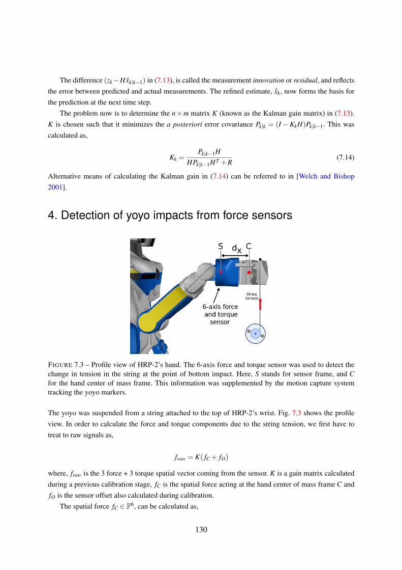
The difference (zk−Hxk|k−1) in (7.13), is called the measurement innovation or residual, and reflects
the error between predicted and actual measurements. The refined estimate, xk, now forms the basis for
the prediction at the next time step.
The problem now is to determine the n×m matrix K (known as the Kalman gain matrix) in (7.13).
K is chosen such that it minimizes the a posteriori error covariance Pk|k = (I −KkH)Pk|k−1. This was
calculated as,
Kk =Pk|k−1H
HPk|k−1HT +R(7.14)
Alternative means of calculating the Kalman gain in (7.14) can be referred to in [Welch and Bishop
2001].
4. Detection of yoyo impacts from force sensors
FIGURE 7.3 – Profile view of HRP-2’s hand. The 6-axis force and torque sensor was used to detect the
change in tension in the string at the point of bottom impact. Here, S stands for sensor frame, and C
for the hand center of mass frame. This information was supplemented by the motion capture system
tracking the yoyo markers.
The yoyo was suspended from a string attached to the top of HRP-2’s wrist. Fig. 7.3 shows the profile
view. In order to calculate the force and torque components due to the string tension, we first have to
treat to raw signals as,
fraw = K( fC + fO)
where, fraw is the 3 force + 3 torque spatial vector coming from the sensor. K is a gain matrix calculated
during a previous calibration stage, fC is the spatial force acting at the hand center of mass frame C and
fO is the sensor offset also calculated during calibration.
The spatial force fC ∈ F6, can be calculated as,
130

Chapter 7 · Annex · § 7.0
fC = [ nCx nCy nCz fx fy fz ]T
where, nCx... are the Cartesian coordinates of the pure couple, nC acting in frame C. Similarly, fx...
represent the force in C. A more detailed explanation of spatial vector algebra can be found in
[Featherstone 2007]. The spatial force fC consists of,
fC = SXFC mg+ fext +ma (7.15)
where, SXFC is the transformation matrix for the force vector from C to the sensor frame S. m is the
mass of the hand, fext the external spatial force acting on it and a the acceleration. The matrix SXFC can
calculated as,
SXFC = (SXC)
−T = (CXS)T
The position and orientation of center of mass frame C relative to sensor frame S is described by a
position vector S pC = [ dx 0 0 ] and a 3×3 rotation matrix SRC. Thus, CXS can be calculated as,
CXS =
[
1 0
s(S pC) 1
][
SRC 0
0 SRC
]
where, s(S pC) is the skew-symmetric matrix of the position vector S pC. Using this formulation we can
calculate the spatial force fext , due to the yoyo in (7.15).
131