modeling of linear and belt object deformation based on
TRANSCRIPT

1OSAKA University, Department of Manufacturing ScienceOSAKA University, Department of Manufacturing Science
Advanced Manufacturing Systems Lab.Advanced Manufacturing Systems Lab.
Modeling of Linear and Belt Object Deformation Modeling of Linear and Belt Object Deformation Based on Differential GeometryBased on Differential Geometry
HidefumiHidefumi Wakamatsu, Wakamatsu, EijiEiji Arai, Arai, andand Shinichi HiraiShinichi Hirai
AgendaAgendaIntroductionIntroductionModeling ofModeling of
Linear Object DeformationLinear Object DeformationApplication to Application to
Linear Object StructureLinear Object StructureModeling ofModeling of
Belt Object DeformationBelt Object DeformationConclusionsConclusions
OSAKA University, Department of Manufacturing ScienceOSAKA University, Department of Manufacturing ScienceAdvanced Manufacturing Systems Lab.Advanced Manufacturing Systems Lab. 2
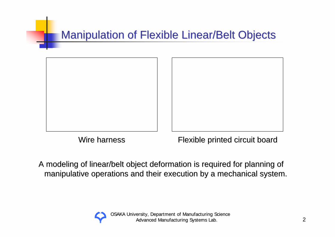
Manipulation of Flexible Linear/Belt ObjectsManipulation of Flexible Linear/Belt Objects
Wire harnessWire harness Flexible printed circuit boardFlexible printed circuit board
A modeling of linear/belt object deformation is required for plaA modeling of linear/belt object deformation is required for planning of nning of manipulative operations and their execution by a mechanical systmanipulative operations and their execution by a mechanical system.em.

OSAKA University, Department of Manufacturing ScienceOSAKA University, Department of Manufacturing ScienceAdvanced Manufacturing Systems Lab.Advanced Manufacturing Systems Lab. 3
FrenetFrenet--SerretSerret FormulasFormulas
⎥⎥⎥
⎦
⎤
⎢⎢⎢
⎣
⎡
⎥⎥⎥
⎦
⎤
⎢⎢⎢
⎣
⎡
−−
−=
⎥⎥⎥
⎦
⎤
⎢⎢⎢
⎣
⎡
′′′
ζηξ
ζηξ
00
0
ξη
ξζ
ηζ
ωωωωωω
⎥⎥⎥
⎦
⎤
⎢⎢⎢
⎣
⎡
⎥⎥⎥
⎦
⎤
⎢⎢⎢
⎣
⎡
−−=
⎥⎥⎥
⎦
⎤
⎢⎢⎢
⎣
⎡
′′′
bnt
bnt
000
00
ττκ
κ
Frenet-Serret formulas Angular verocities of rigid body
t
nb
ξ
η
ζ
ξω
ηω
ζω

OSAKA University, Department of Manufacturing ScienceOSAKA University, Department of Manufacturing ScienceAdvanced Manufacturing Systems Lab.Advanced Manufacturing Systems Lab. 4
Modeling of Linear Object DeformationModeling of Linear Object Deformation
x
y
zOP(s)
ξζ
η
η
x
y
zO
ξ ζP(s)
Assumption :Assumption :Deformation in any direction perpendicular to the central axis oDeformation in any direction perpendicular to the central axis of a linear f a linear
object is negligibleobject is negligible..
L
s
OSAKA University, Department of Manufacturing ScienceOSAKA University, Department of Manufacturing ScienceAdvanced Manufacturing Systems Lab.Advanced Manufacturing Systems Lab. 5
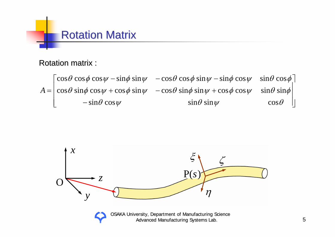
Rotation MatrixRotation Matrix
η
x
y
zO
ξ ζP(s)
⎥⎥⎥
⎦
⎤
⎢⎢⎢
⎣
⎡
−+−+−−−
=θψθψθφθψφψφθψφψφθφθψφψφθψφψφθ
cossin sincos sinsin sincos cos sin sin cossin cos cos sin coscos sincos sin sin cos cossin sin cos cos cos
A
Rotation matrix Rotation matrix ::

OSAKA University, Department of Manufacturing ScienceOSAKA University, Department of Manufacturing ScienceAdvanced Manufacturing Systems Lab.Advanced Manufacturing Systems Lab. 6
Rotation of Object Coordinate SystemRotation of Object Coordinate System
⎥⎥⎥
⎦
⎤
⎢⎢⎢
⎣
⎡
⎥⎥⎥
⎦
⎤
⎢⎢⎢
⎣
⎡
−−
−=
⎥⎥⎥
⎦
⎤
⎢⎢⎢
⎣
⎡
)()()(
00
0
)()()(
sss
sss
dsd
ζηξ
ζηξ
ξη
ξζ
ηζ
ωωωωωω
ξ
η
ζξω
ηω
ζω
( )sP
ζ
η
ξ
( )dss +P
dsd
dsd ψθφωζ += cos
ψθφψθωξ cossinsindsd
dsd
−=
ψθφψθωη sinsincosdsd
dsd
+=
Infinitesimal rotational anglesInfinitesimal rotational angles ::

OSAKA University, Department of Manufacturing ScienceOSAKA University, Department of Manufacturing ScienceAdvanced Manufacturing Systems Lab.Advanced Manufacturing Systems Lab. 7
Infinitesimal Rotational AnglesInfinitesimal Rotational Angles
ηω
ξω
ζω
Vertical bendVertical bend
TwistTwist
Horizontal bendHorizontal bend

OSAKA University, Department of Manufacturing ScienceOSAKA University, Department of Manufacturing ScienceAdvanced Manufacturing Systems Lab.Advanced Manufacturing Systems Lab. 8
Curvature, Curvature, TorsionalTorsional Ratio, and Normal Strain Ratio, and Normal Strain
θφθωωκ ηξ2
22222 sin
dsd
dsd
⎟⎠⎞
⎜⎝⎛+⎟
⎠⎞
⎜⎝⎛=+=
222 cos ⎟
⎠⎞
⎜⎝⎛ +== θφψωω ζ ds
ddsd
Curvature Curvature ::
TorsionalTorsional ratio ratio ::
Normal strain Normal strain :: )(sε

OSAKA University, Department of Manufacturing ScienceOSAKA University, Department of Manufacturing ScienceAdvanced Manufacturing Systems Lab.Advanced Manufacturing Systems Lab. 9
Spatial CoordinatesSpatial Coordinates
η
x
y
zO
ξ ζP(s)
+= )0()( xx s
)0(x
The geometrical shape of a deformed linear object can be represeThe geometrical shape of a deformed linear object can be represented by nted by four functions :four functions : )(),(),(),( ssss εψθφ
{ }∫⎥⎥⎥
⎦
⎤
⎢⎢⎢
⎣
⎡−
s dss
ssss
s0)(cos
)(sin)(sin)(cos)(sin
)(1θ
φθφθ
ε
)(sx
)0P(

OSAKA University, Department of Manufacturing ScienceOSAKA University, Department of Manufacturing ScienceAdvanced Manufacturing Systems Lab.Advanced Manufacturing Systems Lab. 10
Potential EnergyPotential Energy
Uflex =120
L∫ Rfκ2ds
Utor =120
L∫ Rtω2ds
Uext =120
L∫ Reε2ds
Ugrav = Dgx0
L∫ ds
U =Uflex +Utor +Uext +UgravPotential energy :Potential energy :
Gravitational energy :Gravitational energy :
TorsionalTorsional energy :energy :
Flexural energy :Flexural energy :
Extensional energy :Extensional energy :
VariationalVariational principle in principle in staticsstatics ::The potential energy of a linear object attains its minimum valuThe potential energy of a linear object attains its minimum value in its e in its
stable deformed state under the imposed constraints. stable deformed state under the imposed constraints.
: Flexural rigidity: Flexural rigidity
: : TorsionalTorsional rigidityrigidity
: : ExtentionalExtentional rigidityrigidity
: Linear density: Linear density
fR
tR
eR
D

OSAKA University, Department of Manufacturing ScienceOSAKA University, Department of Manufacturing ScienceAdvanced Manufacturing Systems Lab.Advanced Manufacturing Systems Lab. 11
η
ξ
ζ)P( cs
( )( )( ) ⎥
⎥⎥
⎦
⎤
⎢⎢⎢
⎣
⎡=
⎥⎥⎥
⎦
⎤
⎢⎢⎢
⎣
⎡
c
c
c
c
c
c
sss
ψθφ
ψθφ
Positional/Positional/OrientationalOrientational ConstraintsConstraints
⎥⎥⎥
⎦
⎤
⎢⎢⎢
⎣
⎡=−
z
y
x
ab
lll
ss )()( xx
)P( bs
)P( as

OSAKA University, Department of Manufacturing ScienceOSAKA University, Department of Manufacturing ScienceAdvanced Manufacturing Systems Lab.Advanced Manufacturing Systems Lab. 12
( ) ( ) ( )( ) [ ]Lsszsysxf ,0,0,, ∈∀≤
Consideration of Contact with ObstaclesConsideration of Contact with Obstacles
( ) 0,, =zyxf
( ) 0,, >zyxf
Surface Surface ::
Inside Inside ::
Outside Outside :: ( ) 0,, <zyxf

OSAKA University, Department of Manufacturing ScienceOSAKA University, Department of Manufacturing ScienceAdvanced Manufacturing Systems Lab.Advanced Manufacturing Systems Lab. 13
Consideration of SelfConsideration of Self--interactioninteraction
[ ] rssLssrss jijiji 2s.t.,,0,,2)()( ≥−∈∀≥− xx
x(si )x(s j )
2r
The geometrical constraints imposed on a linear object are givenThe geometrical constraints imposed on a linear object are given by not by not only only equationalequational conditions but also inequality conditions.conditions but also inequality conditions.

OSAKA University, Department of Manufacturing ScienceOSAKA University, Department of Manufacturing ScienceAdvanced Manufacturing Systems Lab.Advanced Manufacturing Systems Lab. 14
Minimization ProblemMinimization Problem
[ ]εψθφ aaaaa =
,)()(1∑=
=n
iii seas φφ ,)()(
1∑=
=n
iii seas θθ
,)()(1∑=
=n
iii seas ψψ ∑
==
n
iii seas
1)()( εε
),()( ss ea ⋅= φφ ),()( ss ea ⋅= θθ ),()( ss ea ⋅= ψψ )()( ss ea ⋅= εε
)(aU
),,1(0)( Kkgk L=≤a
),,1(0)( Jjf j L==aMinimize potential energyMinimize potential energy
Subject toSubject to
Positional/Positional/orientationalorientational constraintsconstraints
Avoidance of (selfAvoidance of (self--)interference)interference

OSAKA University, Department of Manufacturing ScienceOSAKA University, Department of Manufacturing ScienceAdvanced Manufacturing Systems Lab.Advanced Manufacturing Systems Lab. 15
Computational ResultsComputational Results
Basis functions:Basis functions:
,,1 21 see ==
,sin12 Lise iπ
=+
)4,3,2,1(cos22 ==+ iLise iπ
OSAKA University, Department of Manufacturing ScienceOSAKA University, Department of Manufacturing ScienceAdvanced Manufacturing Systems Lab.Advanced Manufacturing Systems Lab. 16
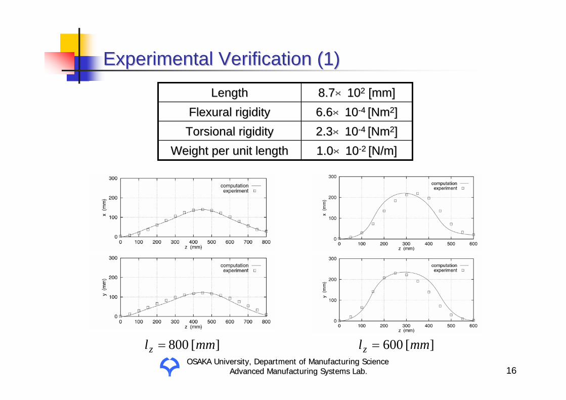
Experimental VerificationExperimental Verification (1)(1)
][800 mmlz = ][600 mmlz =
1.01.0××1010--2 2 [N/m][N/m]Weight per unit lengthWeight per unit length22..33××1010--4 4 [Nm[Nm22]]TorsionalTorsional rigidityrigidity6.66.6××1010--4 4 [Nm[Nm22]]Flexural rigidityFlexural rigidity8.78.7××101022 [mm][mm]LengthLength

OSAKA University, Department of Manufacturing ScienceOSAKA University, Department of Manufacturing ScienceAdvanced Manufacturing Systems Lab.Advanced Manufacturing Systems Lab. 17
Experimental VerificationExperimental Verification (2)(2)
][400 mmlz = ][200 mmlz =

OSAKA University, Department of Manufacturing ScienceOSAKA University, Department of Manufacturing ScienceAdvanced Manufacturing Systems Lab.Advanced Manufacturing Systems Lab. 18
Knotted Shape of Linear ObjectKnotted Shape of Linear Object
,0)()(,0)()(,0)()( 332211 =−=−=− lululu szszszszszsz
ls1
us2
ls3
us1us3ls2 2rx
y z
,0)()(,0)()(,0)()( 332211 =−=−=− lululu sxsxsxsxsxsx
,2)()(,2)()(,2)()( 332211 rsysyrsysyrsysy lululu =−=−=−
Lssssss ululul ≤<<<<<≤ 3213210
[ ]lululu ssssss 332211ψθφ aaaa =

OSAKA University, Department of Manufacturing ScienceOSAKA University, Department of Manufacturing ScienceAdvanced Manufacturing Systems Lab.Advanced Manufacturing Systems Lab. 19
Computational Result of Overhand KnotComputational Result of Overhand Knot

OSAKA University, Department of Manufacturing ScienceOSAKA University, Department of Manufacturing ScienceAdvanced Manufacturing Systems Lab.Advanced Manufacturing Systems Lab. 20
Knitted Shape of Linear ObjectsKnitted Shape of Linear Objects
( )6,5,2,1,0)()( 2 ==− + iszsz ii
( )4,3,)()( 2 ==− − ilsxsx wii
( )6,5,)()( 2 ==− + ilsxsx wii
( )7,3,2)()( 2 ==− − irsysy ii
( )6,2,2)()( 2 ==− + irsysy ii
( )7,,1,0 1 L=≤<≤ + iLss ii1C
2C
3C
4C
8C
7C
6C
5C
wlAssumption :Assumption :The shape of the fabric can be represented by repetitions of theThe shape of the fabric can be represented by repetitions of the same same
shape of one loop.shape of one loop.

OSAKA University, Department of Manufacturing ScienceOSAKA University, Department of Manufacturing ScienceAdvanced Manufacturing Systems Lab.Advanced Manufacturing Systems Lab. 21
Computational Result of Plain Knitted FabricComputational Result of Plain Knitted Fabric
OSAKA University, Department of Manufacturing ScienceOSAKA University, Department of Manufacturing ScienceAdvanced Manufacturing Systems Lab.Advanced Manufacturing Systems Lab. 22
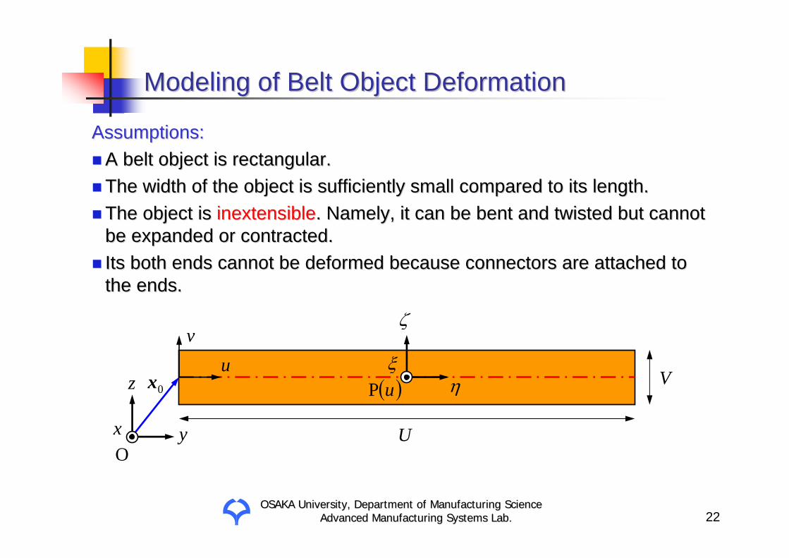
Modeling of Belt Object DeformationModeling of Belt Object Deformation
Assumptions:Assumptions:A belt object is rectangular.A belt object is rectangular.The width of the object is sufficiently small compared to its leThe width of the object is sufficiently small compared to its length.ngth.The object is The object is inextensibleinextensible. Namely, it can be bent and twisted but cannot . Namely, it can be bent and twisted but cannot be expanded or contracted.be expanded or contracted.Its both ends cannot be deformed because connectors are attachedIts both ends cannot be deformed because connectors are attached to to the ends.the ends.
x y
z
O
ξη
ζ
( )uPu
v
U
V0x

OSAKA University, Department of Manufacturing ScienceOSAKA University, Department of Manufacturing ScienceAdvanced Manufacturing Systems Lab.Advanced Manufacturing Systems Lab. 23
Infinitesimal Rotational AnglesInfinitesimal Rotational Angles
ζω
ξω
ηω
BendBend TwistTwist
Shape in Shape in uvuv--spacespace
Assumption:Assumption:A belt object is inextensible.A belt object is inextensible.
0≡ξωIn case of rectangular object: In case of rectangular object:

OSAKA University, Department of Manufacturing ScienceOSAKA University, Department of Manufacturing ScienceAdvanced Manufacturing Systems Lab.Advanced Manufacturing Systems Lab. 24
Developable SurfacesDevelopable Surfaces
Assumption:Assumption:A belt object is inextensible. Its surface is A belt object is inextensible. Its surface is developabledevelopable..Developable surface :Developable surface :
It can be generated by sweeping a straight line in 3D space.It can be generated by sweeping a straight line in 3D space.It includes straight lines.It includes straight lines.
Cylindrical surfaceCylindrical surface Conic surfaceConic surface

OSAKA University, Department of Manufacturing ScienceOSAKA University, Department of Manufacturing ScienceAdvanced Manufacturing Systems Lab.Advanced Manufacturing Systems Lab. 25
Fishbone ModelFishbone Model
)(uα
η
ζ
)(P u::rib anglerib angle
The shape of a belt object:The shape of a belt object:Shape of the bent and twisted Shape of the bent and twisted spine linespine line
Direction of straight Direction of straight rib linesrib lines)(),(),( uuu ψθφ
)(uα
Central axisCentral axis Straight lineStraight lineRib lineRib lineSpine lineSpine line
OSAKA University, Department of Manufacturing ScienceOSAKA University, Department of Manufacturing ScienceAdvanced Manufacturing Systems Lab.Advanced Manufacturing Systems Lab. 26
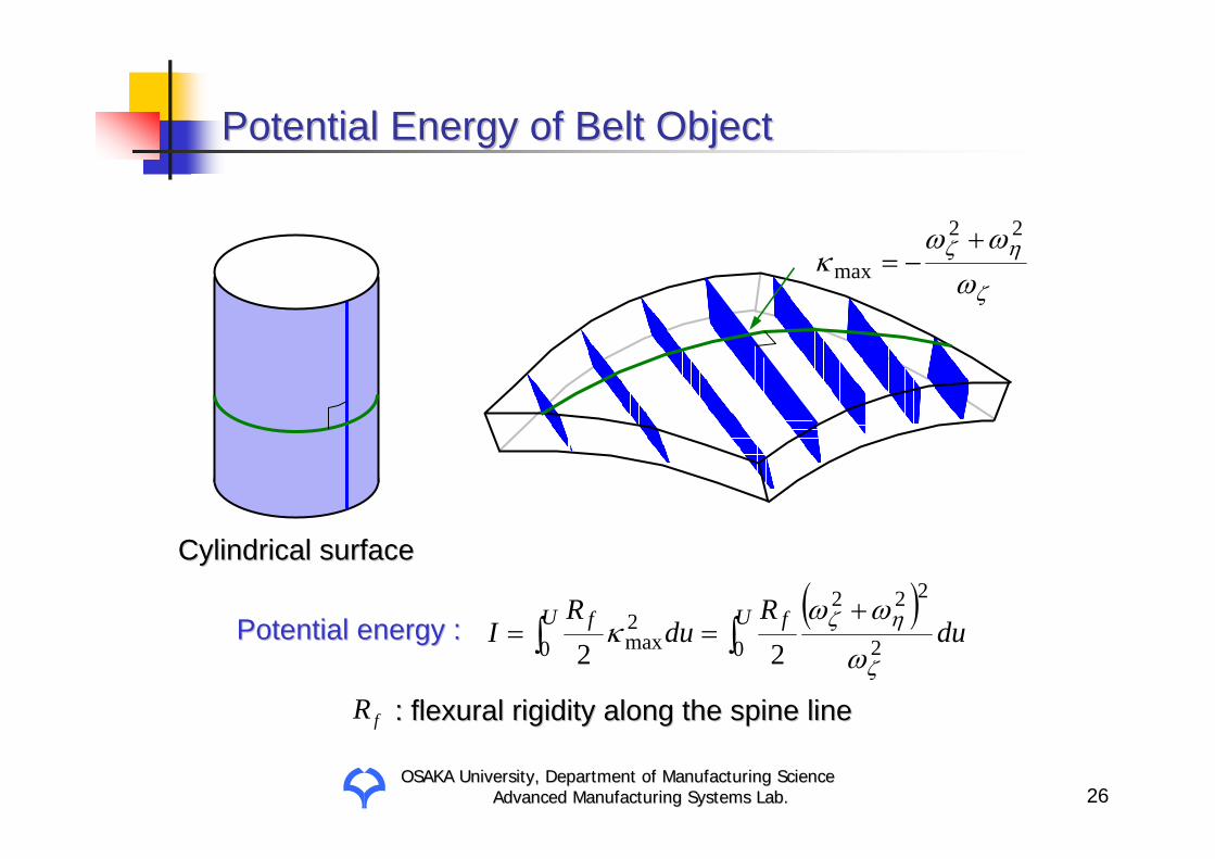
Potential Energy of Belt ObjectPotential Energy of Belt Object
Cylindrical surfaceCylindrical surface
ζ
ηζ
ωωω
κ22
max+
−=
( )∫∫
+== U fU f du
Rdu
RI 0 2
222
02max 22 ζ
ηζ
ω
ωωκPotential energy :Potential energy :
fR : flexural rigidity along the spine line: flexural rigidity along the spine line

OSAKA University, Department of Manufacturing ScienceOSAKA University, Department of Manufacturing ScienceAdvanced Manufacturing Systems Lab.Advanced Manufacturing Systems Lab. 27
ConstraintsConstraints
[ ]UuVdu
dV
,0,cos2cos2 22
∈∀≤≤−ααα
[ ]Uu ,0,tan 1 ∈∀−= −
ζ
η
ωω
α
[ ]Uuu ,0,0 ∈∀=ξω
To prevent rib lines from intersecting To prevent rib lines from intersecting with themselves :with themselves :
Necessary constraints for Necessary constraints for developabilitydevelopabilityTo maintain initial shape in To maintain initial shape in uvuv--space :space :
α αα d+
)(P u du
)(P duu +
Geometric constraintsGeometric constraints
Relationship between the rib angle and Relationship between the rib angle and infinitesimal rotational angles:infinitesimal rotational angles:
ηωζω
α

OSAKA University, Department of Manufacturing ScienceOSAKA University, Department of Manufacturing ScienceAdvanced Manufacturing Systems Lab.Advanced Manufacturing Systems Lab. 28
(a) Computational result(a) Computational result (b) Experimental result(b) Experimental result
Experimental VerificationExperimental Verification
Obverse sideObverse side
Reverse sideReverse side
PolystyrenePolystyrene200[mm] long200[mm] long20[mm] wide20[mm] wide140[140[µµm] thickm] thick

OSAKA University, Department of Manufacturing ScienceOSAKA University, Department of Manufacturing ScienceAdvanced Manufacturing Systems Lab.Advanced Manufacturing Systems Lab. 29
Application to Curved/Bent Belt ObjectApplication to Curved/Bent Belt Object
cκωξ ≡
Curved belt objectCurved belt object Bent belt objectBent belt object
Assumption :Assumption :The rib line at the bent point The rib line at the bent point
coincides with the connecting coincides with the connecting line.line.
connecting lineconnecting line
Shape in Shape in uvuv--space:space:
cκ1

OSAKA University, Department of Manufacturing ScienceOSAKA University, Department of Manufacturing ScienceAdvanced Manufacturing Systems Lab.Advanced Manufacturing Systems Lab. 30
Deformed Shape of Curved Belt ObjectDeformed Shape of Curved Belt Object
(b) Computational result(b) Computational result (c) Experimental result(c) Experimental result
(a) Initial shape(a) Initial shape

OSAKA University, Department of Manufacturing ScienceOSAKA University, Department of Manufacturing ScienceAdvanced Manufacturing Systems Lab.Advanced Manufacturing Systems Lab. 31
Deformed Shape of Bent Belt ObjectDeformed Shape of Bent Belt Object
(b) Computational result(b) Computational result (c) Experimental result(c) Experimental result
(a) Initial shape(a) Initial shape

OSAKA University, Department of Manufacturing ScienceOSAKA University, Department of Manufacturing ScienceAdvanced Manufacturing Systems Lab.Advanced Manufacturing Systems Lab. 32
ConclusionsConclusions
A modeling method of linear/belt object deformation based on difA modeling method of linear/belt object deformation based on differential ferential geometry was proposed.geometry was proposed.
Differential geometry was extended to describe linear object Differential geometry was extended to describe linear object deformation including flexure, torsion, and extension.deformation including flexure, torsion, and extension.
The shape of a linear object can be described by The shape of a linear object can be described by four independent four independent variablesvariables if it is extensible and by three otherwise.if it is extensible and by three otherwise.
It was shown that more complex shapes such as knots and knittedIt was shown that more complex shapes such as knots and knittedfabrics also can be computed using our proposed approach.fabrics also can be computed using our proposed approach.
This approach was applied to deformation of an inextensible belThis approach was applied to deformation of an inextensible belt object. t object.
It was found that the belt object shape can be described by It was found that the belt object shape can be described by two two independent variables.independent variables.