modeling of machine and tool elasticity in coupled … in der umformtechnik modeling of machine and...
TRANSCRIPT
Simulation in der umFormteCHniK
Modeling of Machine and Tool Elasticity in Coupled Forging Simulation M. Tannert, C. Brecher, S. Bäumler, K. Bakarinow Laboratory for Machine Tools and Production Engineering (WZL), RWTH Aachen University, Aachen Abstract
This paper presents an approach for a holistic simulation of forging processes considering
the interactions between forging press, tooling system and forging process. It can be used in
coupled simulations and will enable industrial users in forging industry to do simulation-aided
tool optimizations in the design stage of newly developed forging dies. The final aim is to
reduce the time-consuming experimental optimization process of these dies on the
production machine which nowadays leads to high overall costs.
In forging simulations today the simulated workpiece dimensions significantly deviate from
the real forged workpiece geometry. These deviations are the consequence of relative
displacements between the upper and the lower die which occur in the forging press and
tooling system due to process loads. Customary forging simulation systems do not, however,
offer adequate ways of modeling these interactions, especially in the case of multi-stage
processes.
In order to take the machine-tool-process interactions into account a method was developed
and implemented in a software tool that allows the coupling of forging simulation systems
with external simulation models of the forging press and tooling system. The
parameterization of the external models can be done by results from measurements or
simulation. The method makes it possible to investigate the development of forging errors
caused by the elasticity of press and tooling system for single- and multi-stage processes.
This allows simulation-aided optimization of new forging dies as well as the individual
adaptation to a particular production press prior to first forging tests.
1. Introduction
High dimensional accuracy of the final workpiece is one of the most important targets in
forging. In addition, a long tool life is aspired, which is the basis for cost-effective and highly
productive forging processes that are often performed as multi-stage operations
simultaneously on one press. In many cases, newly developed processes need to undergo
Scient if ic Workshop
Simulation in der umFormteCHniK
an experimental time-consuming optimization process on the production press until the
geometrical accuracy of the final part is reached. This optimization implies a deep and
comprehensive knowledge of the manufacturing technology and leads often to reworking of
dies and tooling system [1-3]. Such problems do not result from the incorrect planning of the
processes, but rather from additional effects that can only be explained by the machine-tool-
process interactions (Figure 1). So the dimensions of forged parts are directly influenced by
the elastic deformations of the forging dies on the one hand and by the displacements in the
die holders and tooling systems as well as in the press on the other hand. Simulation
systems available today not offer adequate ways of modeling and considering the
aforementioned interactions taking place between the workpiece and the tooling system or
press. They provide no possibility, therefore, of achieving simulation-aided tool optimization
in order to minimize the efforts and costs involved in trial-and-error optimization processes.
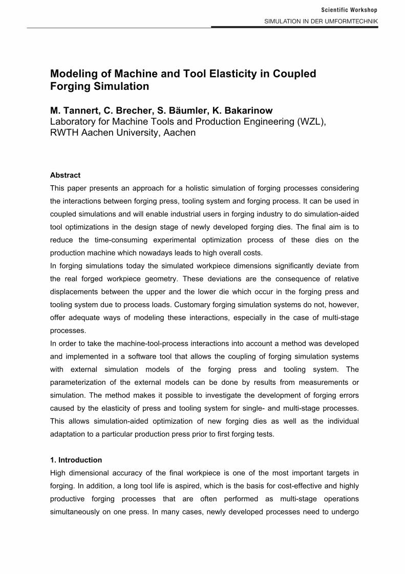
Figure 1: Machine-tool-process interactions
The example in Figure 2 illustrates the interactions taking place in press and tooling system
by a single-stage cold ring upsetting test under various simulation conditions compared to a
forging test [4, 5]. The ring manufactured from steel St52-3 was upset from 50 mm to 34 mm
height using a crank press. The ring's initial outer diameter is 90 mm, its inner diameter is
45 mm and the forging position in the press was -125 mm eccentrically in x-direction. The
high flow stress of the workpiece material causes loads on the press and the tooling system,
resulting in considerable deflections of these components. This, in turn, influences the
workpiece dimensions.
contact conditions
guidances (stiffness,
clearance)
deflection
tilting
horiz. offset
kinematics
process force
material behavior
friction
heat transfer
elastic deformations
in dies and die holders
Press Forging Process
Dies and Tooling System
Interactions
with influence on
forging result
Scient if ic Workshop
Simulation in der umFormteCHniK
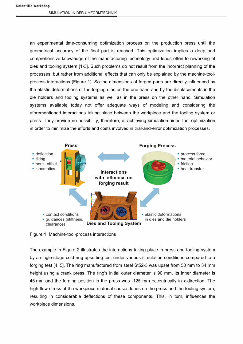
Figure 2: Measured and simulated results of ring upsetting [4]
The investigations with this simple example show, that the results of conventional customary
simulation systems with ideal-rigid or linear-elastic press models do not match well with the
results of the forging test. Better results can be achieved using coupled simulations with
nonlinear-elastic press models, which are able to calculate the influence of press deflection
and tilting on the dimensions of the forged workpiece. In this example an analytical press
model parameterized with measured stiffness and clearance values was used. In addition the
significance of modeling the elastic behavior of dies and die holder systems can be seen as
the workpiece thickness of the upsetting test can only be computed correctly using elastic
models.
In case of multi-stage forging processes with two or more stages in tool contact at any point
in time, the interactions between the forging processes and the machine are considerably
more complex due to the individual tool stages are influencing each other, too. As all process
stages in a multi-stage die contribute to the overall load on the press, alterations to just one
stage is enough to cause the press load and thus press deflection response to change,
thereby influencing all present stages of the process.
Investigation and modeling of the interactions between forging process, press and tools in
simulation was thus the object of numerous research activities in bulk and also sheet metal
forming over recent years. An overview is given in [6] and [7].
2. Approaches for modeling machine and tool elasticity in forging simulation
In order to consider the occurring deformations in tools and press, the FE simulation has to
be able to predict them. In [8] the possible deformations are differentiated between local and
global elastic deformations which result from different reasons. There are local deformations
Example Forging Mean thickness of forged
workpiece mm
Forging test 34.9
Simulation Rigid diesElastic dies/
die holders
Conventional
simulation
Ideal-rigid press model33.1
( = -1.8)
33.6
( = -1.3)
Linear-elastic press
model
34.1
( = -0.8)
34.5
( = -0.4)
Coupled
simulation
Nonlinear-elastic
analytical press model
34.6
( = -0.3)
34.9
( = 0.0) 35.1
34.8
35.0 34.8
33.1
33.1
33.133.1
Forging test
Simulation
Scient if ic Workshop

Simulation in der umFormteCHniK
of the dies, global deflections of the die holders or tooling systems and global dislocations as
an influence of the press.
Commercial, special-purpose Finite Element (FE) forging simulation systems, e.g.
Simufact.forming®, FORGE®, DEFORM® or AutoForm®, are mainly used in forging industry
today to observe material flow and capture defects or to calculate the press forces and die
stresses [9]. These systems offer capabilities to simulate local deformations of the dies by
using volume elements and linear-elastic material models. However, in case of large tool
models, e.g. die holder systems or multi-stage processes, this leads to unacceptable
preprocessing effort and computational times for industrial applications [10].
In almost all cases, local deformations are small compared to global tool deflections and tool
dislocations. Of course, global tool deflections or dislocations can also be modeled as elastic
bodies for tooling system and press within the FE simulation but with the aforementioned
problems of large models. Therefore, different approaches for coupling FE workpiece models
and press or tooling system models were developed. Basic coupling concepts are presented
in [11] and [12]. Figure 3 shows three general coupling principles which are classified
according to their method of integration in offline-coupling, model integration and co-
simulation.
Figure 3: Approaches to consider process-machine/tooling system interactions [11, 12]
In offline-coupling the process simulation and the machine simulation are calculated
separately. The process force progressions of the entire forming process are computed with
Offline-Coupling
iterative between various
simulation environments
without active interaction
convergence between the
simulations is critical
Processsimulation
Machinesimulation
Load
Processmodel
Response
Machinemodel
Model Integration
in a cycle within one
simulation environment and
direct interaction
enhancement of either the
process or the machine
model and integration of the
(simplified) other model
Enhanced process ormachine simulation
Processmodel
Load ResponseLoad Response
Machinemodel
Co-Simulation
in a synchronized cycle
between various simulation
environments
active process manipulation,
controlled subsystems
(drives, compensation,
hydraulics)
Synchronization
Machinemodel
Processsimulation
Machine simulation
Processmodel
ResponseLoad
Scient if ic Workshop
Simulation in der umFormteCHniK
the workpiece model in a first step. These process force progressions are transferred to the
machine simulation, where the press behavior is computed. Subsequently, the adjusted ram
movement, as a result of the machine simulation serves as a boundary condition for the FE
simulation, if a new calculation by the two models is performed by means of an iterative loop.
The cycle can be repeated until convergence of the simulations is reached. The most
important advantage of offline coupled simulations is that both simulations are implemented
in their common software environment and benefit from the tools, which are available in the
typical software environment. The disadvantage of this approach is the fact, that no dynamic
interaction can be simulated and that the calculation time increases due to repeated
calculations, because one simulation typically uses the complete results from an entire run of
the other one. Examples for offline-coupling are presented in [13] and [14].
The approach named model integration uses one simulation environment to model the press
elasticity and the forming process. Usually, the workpiece model within the FE simulation is
extended by a simplified press model. The tilt and the vertical deflection of the press ram can
be taken into consideration by means of discrete spring and damping elements. General-
purpose simulation systems, such as MARC®, ABAQUS® or LS-DYNA®, provide the
prerequisite for using this approach but these systems are complex and therefore not very
often used in industry.
Some typical forging simulation systems also allow modeling of press elasticity by model
integration. Using the simulation system FORGE®, for example, it is possible to define linear-
elastic stiffness behavior of the press in 6 dimensions, which means translation in x-, y-, and
z-direction and rotation around these axes [15]. The computation “conventional simulation/
linear elastic press model” in Figure 2 was performed using this feature. The simulation
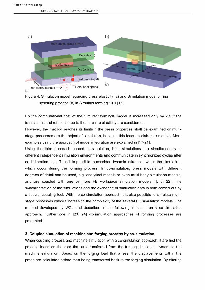
system Simufact.forming® even provides the opportunity to model non-linear elastic press
behavior [16]. Figure 4 shows the approach that uses translatory and rotational springs,
which can be defined by a parameter input tables. In this way clearance and different
elasticity behavior depending on the axis direction can be considered. Simulation results of
the ring upsetting from Figure 2 with Simufact.forming® in [16] coincide with the results in [4,
5] using coupled simulation (co-simulation approach).
The advantage of an integrated model of the press in the forging process simulation is the
direct interaction accompanied by high numerical stability with stable contact situations. This
improves the accuracy of the forming simulation and makes the computation less time
consuming than other approaches.
Scient if ic Workshop
Simulation in der umFormteCHniK
Figure 4: Simulation model regarding press elasticity (a) and Simulation model of ring
upsetting process (b) in Simufact.forming 10.1 [16]
So the computational cost of the Simufact.forming® model is increased only by 2% if the
translations and rotations due to the machine elasticity are considered.
However, the method reaches its limits if the press properties shall be examined or multi-
stage processes are the object of simulation, because this leads to elaborate models. More
examples using the approach of model integration are explained in [17-21].
Using the third approach named co-simulation, both simulations run simultaneously in
different independent simulation environments and communicate in synchronized cycles after
each iteration step. Thus it is possible to consider dynamic influences within the simulation,
which occur during the forming process. In co-simulation, press models with different
degrees of detail can be used, e.g. analytical models or even multi-body simulation models,
and are coupled with one or more FE workpiece simulation models [4, 5, 22]. The
synchronization of the simulations and the exchange of simulation data is both carried out by
a special coupling tool. With the co-simulation approach it is also possible to simulate multi-
stage processes without increasing the complexity of the several FE simulation models. The
method developed by WZL and described in the following is based on a co-simulation
approach. Furthermore in [23, 24] co-simulation approaches of forming processes are
presented.
3. Coupled simulation of machine and forging process by co-simulation
When coupling process and machine simulation with a co-simulation approach, it are first the
process loads on the dies that are transferred from the forging simulation system to the
machine simulation. Based on the forging load that arises, the displacements within the
press are calculated before then being transferred back to the forging simulation. By altering
Ram (rigid, press driven)
Bed plate (rigid)
Die (elastic)
Die (elastic)
Rotational springTranslatory springs
Workpiece
a) b)
Scient if ic Workshop
Simulation in der umFormteCHniK
the finite element mesh of the tools in the forging simulation in accordance with the
displacement and tilting behavior of the press, machine behavior is completely taken into
account during the simulation of the forging process. The complex interaction between tool
displacement, the change in material flow which results from this, and the altered press load
can be calculated in comprehensive detail.
The coupling is achieved in each case between two simulation time increments of the forging
simulation and controlled by a software tool called “GekoSim”. As commercially available
forging simulation systems do not supply the necessary data interface for coupled
simulations, system FORGE® was first provided with the necessary functionality to develop
the method. Current research work focuses the coupling with DEFORM®, AutoForm® and
Simufact.forming®.
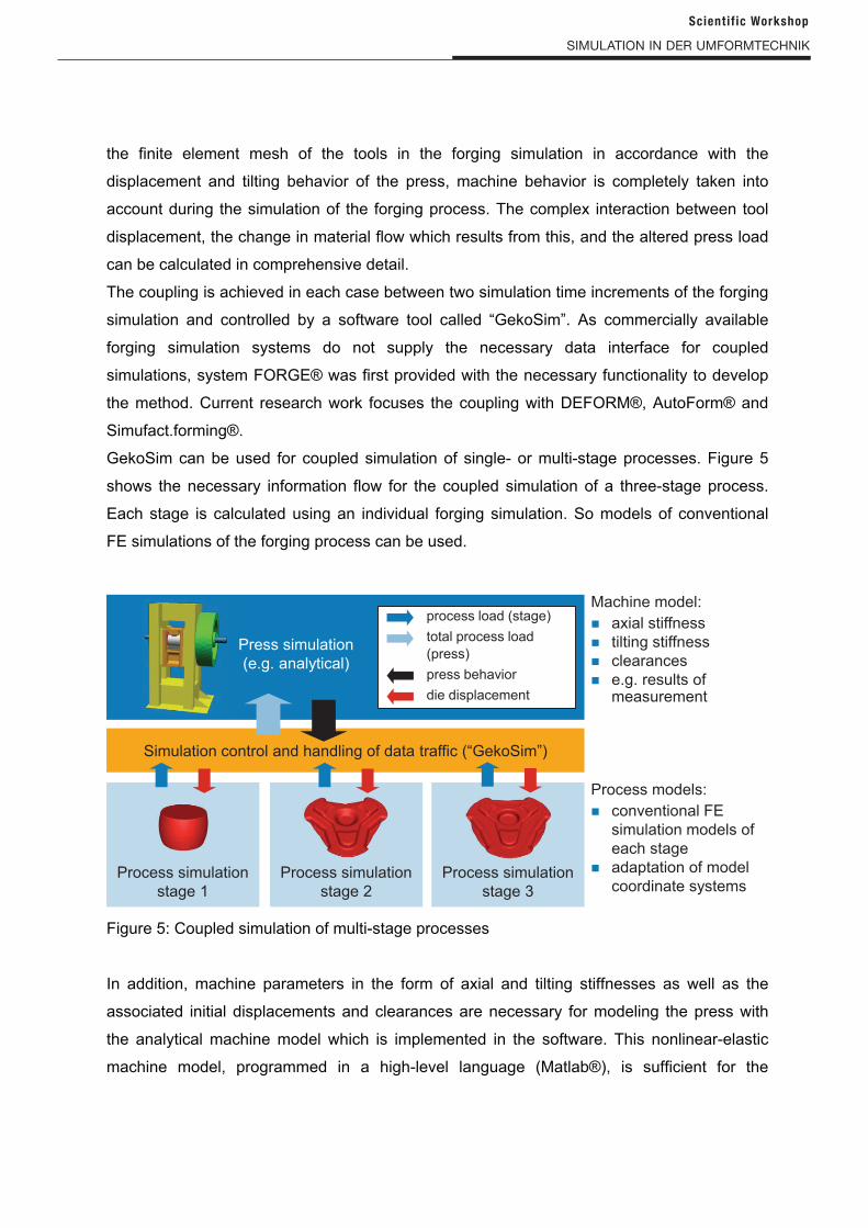
GekoSim can be used for coupled simulation of single- or multi-stage processes. Figure 5
shows the necessary information flow for the coupled simulation of a three-stage process.
Each stage is calculated using an individual forging simulation. So models of conventional
FE simulations of the forging process can be used.
Figure 5: Coupled simulation of multi-stage processes
In addition, machine parameters in the form of axial and tilting stiffnesses as well as the
associated initial displacements and clearances are necessary for modeling the press with
the analytical machine model which is implemented in the software. This nonlinear-elastic
machine model, programmed in a high-level language (Matlab®), is sufficient for the
Simulation control and handling of data traffic (“GekoSim”)
Press simulation
(e.g. analytical)
Process simulation
stage 1
Process simulation
stage 2
Process simulation
stage 3
process load (stage)
total process load
(press)
press behavior
die displacement
Machine model:
Process models:
axial stiffness
tilting stiffness
clearances
e.g. results of measurement
conventional FE
simulation models of
each stage
adaptation of model
coordinate systems
Scient if ic Workshop
Simulation in der umFormteCHniK
simulation of the machine behavior of most forging presses. The required machine
parameters may be determined by means of measurement, for example.
Detailed information about the method of coupled simulation, the software “GekoSim” and
the available machine models can be found in [22] for single-stage and [5, 23] for multi-stage
processes.
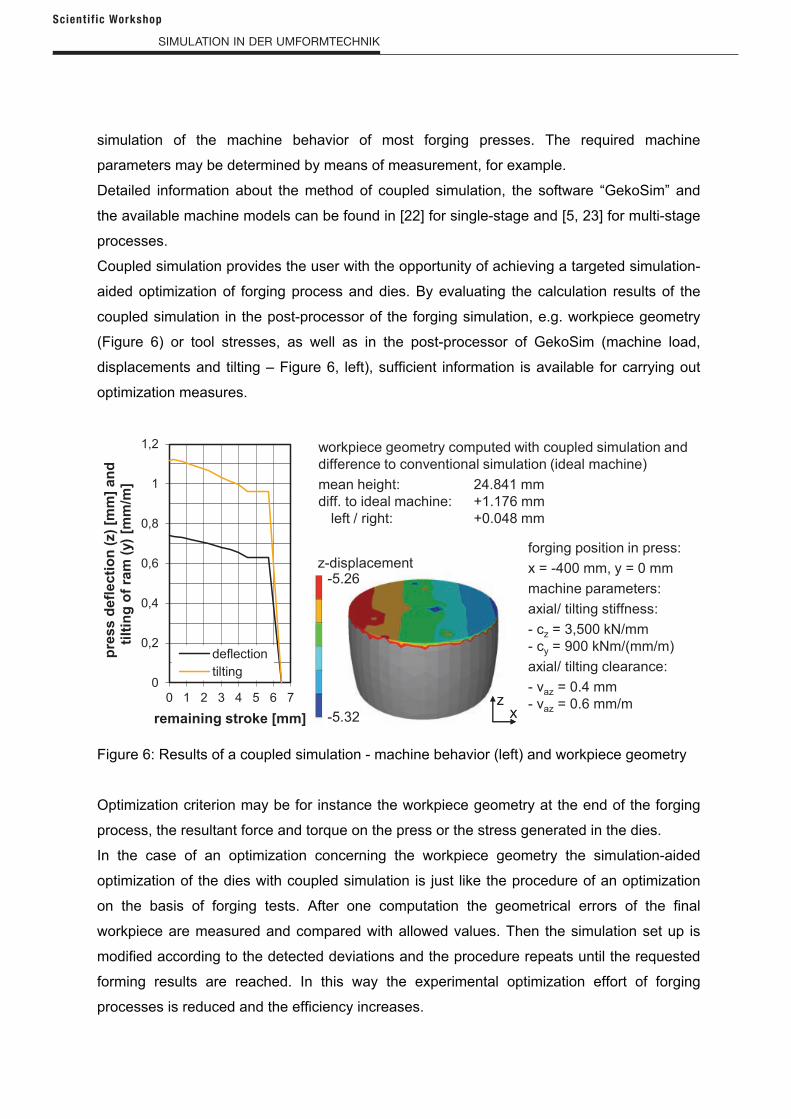
Coupled simulation provides the user with the opportunity of achieving a targeted simulation-
aided optimization of forging process and dies. By evaluating the calculation results of the
coupled simulation in the post-processor of the forging simulation, e.g. workpiece geometry
(Figure 6) or tool stresses, as well as in the post-processor of GekoSim (machine load,
displacements and tilting – Figure 6, left), sufficient information is available for carrying out
optimization measures.
Figure 6: Results of a coupled simulation - machine behavior (left) and workpiece geometry
Optimization criterion may be for instance the workpiece geometry at the end of the forging
process, the resultant force and torque on the press or the stress generated in the dies.
In the case of an optimization concerning the workpiece geometry the simulation-aided
optimization of the dies with coupled simulation is just like the procedure of an optimization
on the basis of forging tests. After one computation the geometrical errors of the final
workpiece are measured and compared with allowed values. Then the simulation set up is
modified according to the detected deviations and the procedure repeats until the requested
forming results are reached. In this way the experimental optimization effort of forging
processes is reduced and the efficiency increases.
X
Z
X
Z
workpiece geometry computed with coupled simulation and
difference to conventional simulation (ideal machine)
mean height: 24.841 mm
diff. to ideal machine: +1.176 mm
left / right: +0.048 mm
forging position in press:
x = -400 mm, y = 0 mm
machine parameters:
axial/ tilting stiffness:
- cz = 3,500 kN/mm
- cy = 900 kNm/(mm/m)
axial/ tilting clearance:
- vaz = 0.4 mm
- vaz = 0.6 mm/m-5.32
-5.26z-displacement
0
0,2
0,4
0,6
0,8
1
1,2
0 1 2 3 4 5 6 7
pre
ss
de
fle
cti
on
(z)
[mm
] a
nd
tilt
ing
of
ram
(y)
[mm
/m]_
remaining stroke [mm]
deflection
tilting
Scient if ic Workshop
Simulation in der umFormteCHniK
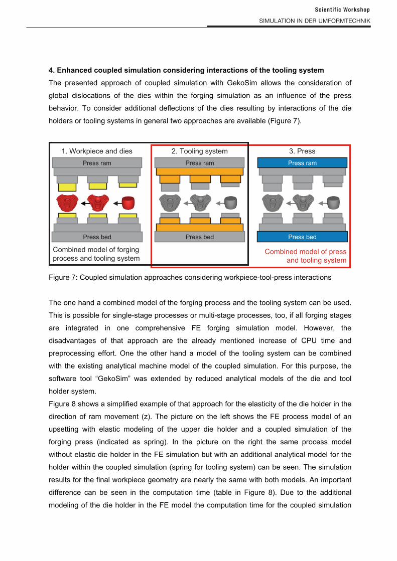
4. Enhanced coupled simulation considering interactions of the tooling system
The presented approach of coupled simulation with GekoSim allows the consideration of
global dislocations of the dies within the forging simulation as an influence of the press
behavior. To consider additional deflections of the dies resulting by interactions of the die
holders or tooling systems in general two approaches are available (Figure 7).
Figure 7: Coupled simulation approaches considering workpiece-tool-press interactions
The one hand a combined model of the forging process and the tooling system can be used.
This is possible for single-stage processes or multi-stage processes, too, if all forging stages
are integrated in one comprehensive FE forging simulation model. However, the
disadvantages of that approach are the already mentioned increase of CPU time and
preprocessing effort. One the other hand a model of the tooling system can be combined
with the existing analytical machine model of the coupled simulation. For this purpose, the
software tool “GekoSim” was extended by reduced analytical models of the die and tool
holder system.
Figure 8 shows a simplified example of that approach for the elasticity of the die holder in the
direction of ram movement (z). The picture on the left shows the FE process model of an
upsetting with elastic modeling of the upper die holder and a coupled simulation of the
forging press (indicated as spring). In the picture on the right the same process model
without elastic die holder in the FE simulation but with an additional analytical model for the
holder within the coupled simulation (spring for tooling system) can be seen. The simulation
results for the final workpiece geometry are nearly the same with both models. An important
difference can be seen in the computation time (table in Figure 8). Due to the additional
modeling of the die holder in the FE model the computation time for the coupled simulation
Press ram
Press bedPress bed
Press ram
Press bed
Press ram
1. Workpiece and dies 2. Tooling system 3. Press
Combined model of forging
process and tooling systemCombined model of press
and tooling system
Scient if ic Workshop
Simulation in der umFormteCHniK
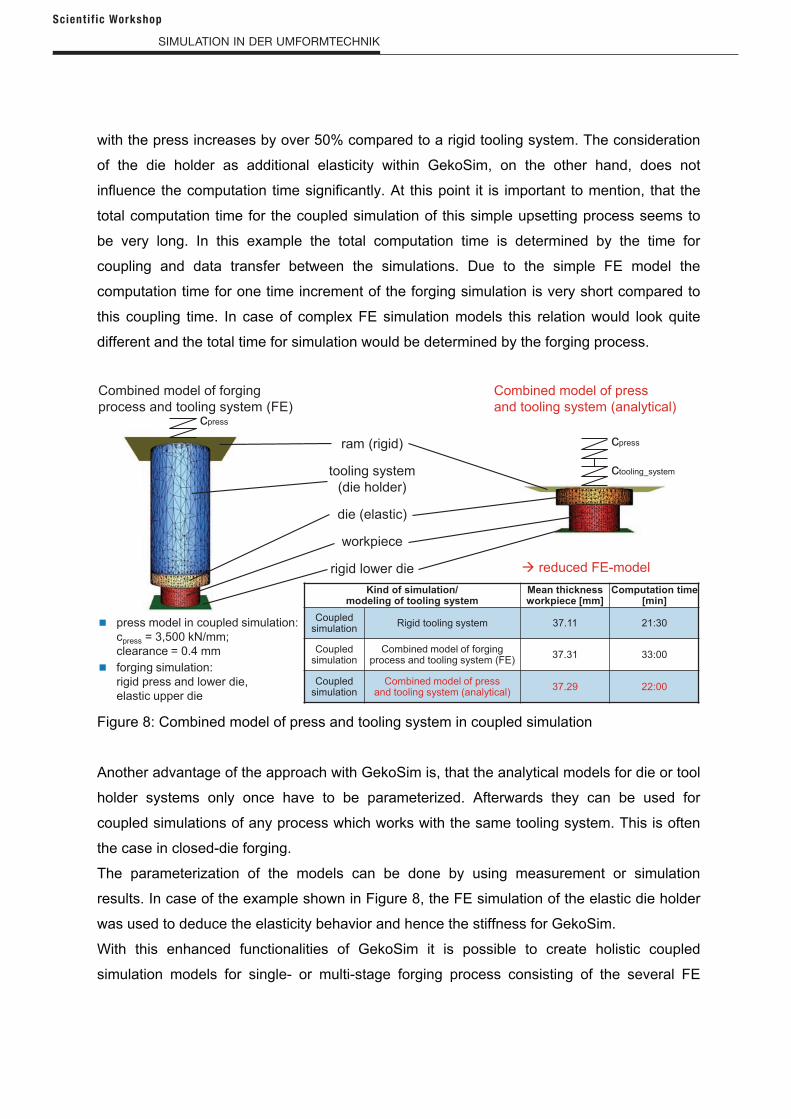
with the press increases by over 50% compared to a rigid tooling system. The consideration
of the die holder as additional elasticity within GekoSim, on the other hand, does not
influence the computation time significantly. At this point it is important to mention, that the
total computation time for the coupled simulation of this simple upsetting process seems to
be very long. In this example the total computation time is determined by the time for
coupling and data transfer between the simulations. Due to the simple FE model the
computation time for one time increment of the forging simulation is very short compared to
this coupling time. In case of complex FE simulation models this relation would look quite
different and the total time for simulation would be determined by the forging process.
Figure 8: Combined model of press and tooling system in coupled simulation
Another advantage of the approach with GekoSim is, that the analytical models for die or tool
holder systems only once have to be parameterized. Afterwards they can be used for
coupled simulations of any process which works with the same tooling system. This is often
the case in closed-die forging.
The parameterization of the models can be done by using measurement or simulation
results. In case of the example shown in Figure 8, the FE simulation of the elastic die holder
was used to deduce the elasticity behavior and hence the stiffness for GekoSim.
With this enhanced functionalities of GekoSim it is possible to create holistic coupled
simulation models for single- or multi-stage forging process consisting of the several FE
Combined model of press
and tooling system (analytical)
Combined model of forging
process and tooling system (FE)
cpressram (rigid)
tooling system
(die holder)
die (elastic)
workpiece
rigid lower die reduced FE-model
ctooling_system
cpress
Kind of simulation/modeling of tooling system
Mean thickness workpiece [mm]
Computation time[min]
Coupled simulation
Rigid tooling system 37.11 21:30
Coupled simulation
Combined model of forgingprocess and tooling system (FE)
37.31 33:00
Coupled simulation
Combined model of pressand tooling system (analytical)
37.29 22:00
press model in coupled simulation:
cpress = 3,500 kN/mm;
clearance = 0.4 mm
forging simulation:
rigid press and lower die,
elastic upper die
Scient if ic Workshop
Simulation in der umFormteCHniK
forging process simulations and a combined analytical model of the press and the tooling
system.
5. Parameter investigation for models of machine and tooling system
The accuracy of a forming process is decisive defined by the deflection and tilting behavior of
the press and the tooling system under process load. To characterize the press in simulation,
the axial and tilting stiffness as well as the associated initial displacement and clearance is
used. For presses, the standardized measurement of these machine parameters is carried
out at the bottom dead centre position of the ram and with a static load according e.g. to
guideline DIN 55189 [24]. Furthermore, in [25] an approach for the dynamic measurement of
axial and tilting stiffness is given.
Knowledge of the press parameters for stiffness and clearance is not sufficient to draw direct
conclusions regarding machine behavior during the forming process. This is because, in
most cases, the press loads during the process are unknown. Measurements during the
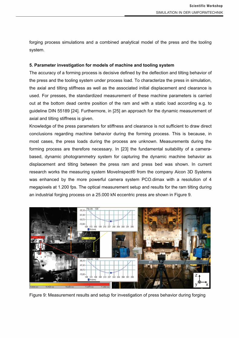
forming process are therefore necessary. In [23] the fundamental suitability of a camera-
based, dynamic photogrammetry system for capturing the dynamic machine behavior as
displacement and tilting between the press ram and press bed was shown. In current
research works the measuring system MoveInspect® from the company Aicon 3D Systems
was enhanced by the more powerful camera system PCO.dimax with a resolution of 4
megapixels at 1.200 fps. The optical measurement setup and results for the ram tilting during
an industrial forging process on a 25.000 kN eccentric press are shown in Figure 9.
Figure 9: Measurement results and setup for investigation of press behavior during forging
x
z
yx
Scient if ic Workshop
Simulation in der umFormteCHniK
Besides the optical measurement a measurement with four tactile displacement transducers
was carried out. The calculation of the tilting between press ram and bed was done
according to DIN 55189 [24] with the displacement sensors on the one hand and the
photogrammetric measurement results on other hand. Using the high end cameras the
deviation between the two measurements is only up to 3% for vertical ram deflection and up
to 5% for tilting around y-axis.
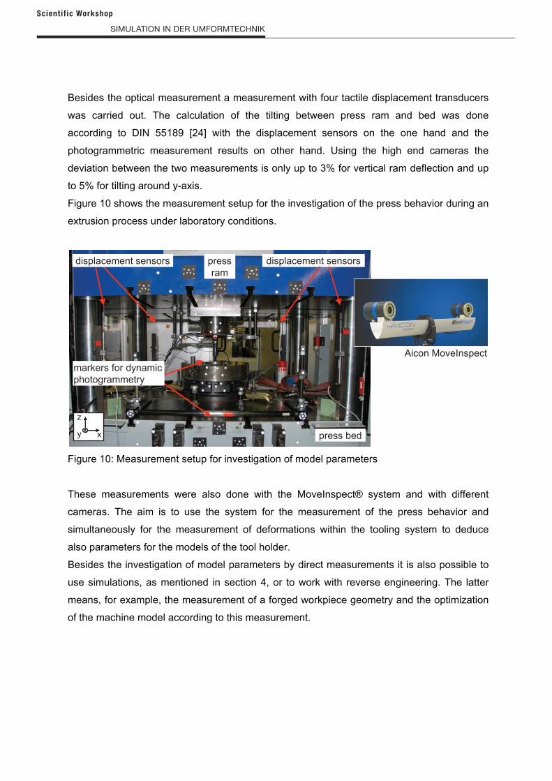
Figure 10 shows the measurement setup for the investigation of the press behavior during an
extrusion process under laboratory conditions.
Figure 10: Measurement setup for investigation of model parameters
These measurements were also done with the MoveInspect® system and with different
cameras. The aim is to use the system for the measurement of the press behavior and
simultaneously for the measurement of deformations within the tooling system to deduce
also parameters for the models of the tool holder.
Besides the investigation of model parameters by direct measurements it is also possible to
use simulations, as mentioned in section 4, or to work with reverse engineering. The latter
means, for example, the measurement of a forged workpiece geometry and the optimization
of the machine model according to this measurement.
x
z
yx
press
ram
press bed
displacement sensors displacement sensors
markers for dynamic
photogrammetry
Aicon MoveInspect
Scient if ic Workshop
Simulation in der umFormteCHniK
6. Outlook for Simufact.forming®
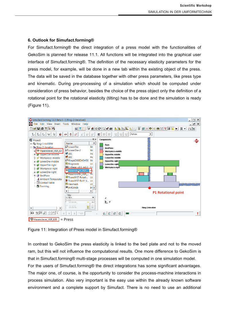
For Simufact.forming® the direct integration of a press model with the functionalities of
GekoSim is planned for release 11.1. All functions will be integrated into the graphical user
interface of Simufact.forming®. The definition of the necessary elasticity parameters for the
press model, for example, will be done in a new tab within the existing object of the press.
The data will be saved in the database together with other press parameters, like press type
and kinematic. During pre-processing of a simulation which should be computed under
consideration of press behavior, besides the choice of the press object only the definition of a
rotational point for the rotational elasticity (tilting) has to be done and the simulation is ready
(Figure 11).
Figure 11: Integration of Press model in Simufact.forming®
In contrast to GekoSim the press elasticity is linked to the bed plate and not to the moved
ram, but this will not influence the computational results. One more difference to GekoSim is
that in Simufact.forming® multi-stage processes will be computed in one simulation model.
For the users of Simufact.forming® the direct integrations has some significant advantages.
The major one, of course, is the opportunity to consider the process-machine interactions in
process simulation. Also very important is the easy use within the already known software
environment and a complete support by Simufact. There is no need to use an additional
Scient if ic Workshop
Simulation in der umFormteCHniK
software package. For the simulation itself the direct integration has the advantage of high
numerical convergence with stable contact situations which leads high simulation stability.
7. Summary
An approach of coupled simulation was presented which considers the workpiece-tool-press
interactions in the FE simulation of forging processes. The method makes it possible to
reconstruct the development of forging errors caused by the press in single- and multi-stage
processes by simulation.
In addition to the workpiece-based interaction of the different forging stages in multi-stage
processes, where only one stage is in contact with the tools at any point in time, the
machine-based interaction is also taken into account by using coupled simulation software
GekoSim. It is these two interactions in particular that represent a challenge when optimizing
multi-stage processes with two or more active stages.
In present work the coupled simulation approach was enhanced to include the interactions
with the tooling system in the forging simulation in an easy way, too. Furthermore a direct
implementation of the GekoSim functionalities to Simufact.forming® is in progress.
Prediction of the mentioned interaction results through simulations represents a significant
improvement over the state of the art in forging simulations and can help to perform
simulation-aided process optimizations. Optimization criterion may be for instance the
workpiece geometry at the end of the forging process, the resultant force and torque on the
press or the stress generated in the dies. The procedure of such optimizations is just like the
experimental procedure on the basis of forging tests, but in a virtual way. So the
experimental optimization effort of forging processes can be reduced and the efficiency
increases.
Furthermore, in current research work a dynamic photogrammetry measuring system gets
enhanced by more powerful cameras and better measuring strategy with the aim to use the
system for measuring deflections and deformations within the press and the tooling system
simultaneously during the forging process. As in a feedback loop, the simulation results then
can be compared with observed experimental data. This enables the researcher and not at
least the simulation user in industry to gain a closer understanding of the details of process-
machine interactions in forging.
Scient if ic Workshop
Simulation in der umFormteCHniK
Scient if ic Workshop
8. Acknowledgments
The authors would like to thank Stiftung Industrieforschung and Industrieverband
Massivumformung e.V. (German foundation for industry research and the federation of metal
forging companies) for supporting the research projects SI S 789 “Optimierung von
Mehrstufenwerkzeugen durch gekoppelte Simulation von Maschine und Prozess
(Optimization of multi-stage forging processes by coupled simulation of the machine and the
forging process)” and SI S 683 “Gekoppelte Simulation von Massivumformprozess und
Maschine (Coupled simulation of machine and process in forging)”. The final reports are
available in the German language at Forschungsgesellschaft Stahlverformung e.V., Goldene
Pforte 1, 58093 Hagen, Germany. The depicted IGF research project „Messtechnische und
simulative Quantifizierung des Werkzeugverhaltens in der Massivumformung (Metrological
and simulative quantification of tooling systems behavior in forging)“ (16707 N / 1) of
Forschungsgesellschaft Stahlverformung e.V., Goldene Pforte 1, 58093 Hagen, Germany is
supported via AiF by the German Federal Ministry of Economics and Technology on the
basis of a decision by the German Bundestag.
Furthermore, the authors would like to thank the industrial partners of the project working
groups for supporting the research works.
8. References
[1] Doege, E., Klawitter, G., 1999, Vom Lastenheft zum Schmiedewerkzeug, die CA-
Entwicklungskette in der Schmiedetechnologie. Umformtechnik 2000 Plus, Bamberg,
Meisenbach, 121-128.
[2] Slagter, W., Hambrecht, J., 2002, Schmiedesimulation: Umfrageergebnisse zur
Wirtschaftlichkeit, Schmiede-J., September 2002:14-16.
[3] Stalmann, A., Weigert, P., 2009, Werkzeugtechnik der Zukunft – Anforderungen und
Möglichkeiten, EFB Servopressen und Werkzeugsysteme zur Blechverarbeitung, 93-
106.
[4] Brecher, C., Schapp, L., 2007, Vorstoß in neue Dimensionen: Kopplung der
Umformsimulation mit nicht-linearen Pressenmodellen. VDI-Berichte Nr. 1993 Conf.
„Massivumformung: Produkte – Partner – Perspektiven“, Leonberg, Germany, VDI-
Verlag, 117-128.
[5] Brecher, C., Schapp, L., Tannert, M., 2008, Simulation-Aided Optimization of Multi-
Stage Dies – Coupled Simulation of Forging Processes with Non-Linear-Elastic
Machine Models. Proc. of 1st Int. Conf. on Process Machine Interactions (PMI),
Hannover, Germany, 167-174.