modeling of powder bed processing a review
TRANSCRIPT

Modeling of Powder Bed Processing – A Review
Aaron Flood* and Frank Liou*
*Department of Mechanical and Aerospace Engineering, Missouri University of Science and
Technology, Rolla, MO, 65409
Abstract
Many models have been developed to model powder beds and these methods can be
implemented to model a powder bed for Selective Laser Sintering, Selective Laser Melting and
any other technique of additive manufacturing which uses powder beds. Two of the main
systems are the Discrete Element Method (DEM) and the Geometric Method. The purpose of
this paper is to analyze each of the methods. It will first highlight how each of the models creates
the powder bed. The next aspect reviewed is the computational time and its causes. And lastly,
each of the methods will be examined for their accuracy as shown from various experiments that
have been reported in literature. In addition to these methods, there are several others that have
been proposed that will also be studied and compared to highlight the strengths and weaknesses
of each.
Introduction
Multiple fields of science are interested in the simulation of a powder bed for various different
applications; some of these fields include physics, chemistry, and engineering. Each of these
areas of science have their own needs for what data is to be collected from the models that they
create. Since there is such a wide range of needs for the data being collected, there is as also a
wide range of need for the types of models that are in the literature. Most of the models studied
assumed that the powder particles could be represented by perfect spheres. This would help to
simplify the calculations performed by the system. Another generalization that can be made
about the various systems is that the powder particles are incompressible. This results in again a
much simpler and easier to implement model. When reviewing these systems, there are several
aspects which can be compared to determine which method is best for each application. The
main controls that are analyzed are the computational time required and the mechanical
properties of the powder bed created. In addition to these main model characteristics, the results
from the various models are compared to experimental data to validate their results. This
validation is two-fold. The first piece of data used to validate the simulation is the packing
density of the model. This is done by taking the total volume of the spheres and dividing it by
the volume of the powder bed, which is the complement of the void fraction. The other
benchmark which is used to determine the effectiveness of a model is to calculate the average
coordination number. The coordination number is the number of contacts that a particle has with
its surrounding particles. Therefore, the coordination number of a powder bed is the average
coordination number of all of the particles. This value is very difficult to determine
experimentally, therefore it is commonly used to compare various models and not used to
1118
validate them. Overall, these two parameters are used to determine the effectiveness of a model
and to compare models.
The models reviewed here only take into account the creation of the powder bed. There are
several models in research which will model not only the creation of the powder bed, but will
also model the melting of the powder particles and the creation of the final product. One
representative paper is by King et. al. [1] which starts by laying particles over a Cartesian mesh
background. Once the powder bed is created, several mechanisms are utilized to model the
melting and other processes which occur. Some of the main processes included are: absorption,
vaporization, capillary forces, gravity, convection, conduction, phase transformation, and many
others. This model will first create the powder bed and then calculate the effect that the laser
imposes on the powder particles based on these forces. This paper [1] is similar to other papers
such as [2], [3] and [4] which all have some variation of modeling process which predicts the
finished product. These models are not reviewed in depth in this work due to a slightly different
focus. This research is focused solely on the creation of the powder bed. Therefore, the
information in this paper is the foundation on which the other research can be conducted.
Discrete Element Method
The use of the discrete element method (DEM) began in 1979 by Cundal et. al. [5]. Their new
method was to track the contact forces of a given particle throughout the entire simulation
process. This idea has integrated itself into the simulation of powder beds. There are several
different approaches that have been used in an attempt to model a powder bed using this method.
Each of the DEM models starts out in a very similar way. To begin either one particle is selected
and placed arbitrarily above the container as in [6] or multiple particles are generated and placed
over the container as in [7]. These particles are selected to have different distributions. Some of
the more rudimentary approaches use a mono-sphere approach. The more elaborate models use
a distribution of radii to determine the size of the particles. The most common distribution is a
normal distribution centered on the mean particle size. Once the particles are created, they are
released and allowed to fall depending on the forces that are being used by the current
simulation. All of the models that were found had several of the basic forces in common but, in
an attempt to increase the accuracy of the model, some authors have added other forces which
manifest themselves in smaller amounts. To begin, the major forces which are present in all of
the simulations include the force of gravity, contact forces, and the force of friction. In most
cases these are represented by Newton's second law of motion which is shown in equation 1. [8]
Where translational and angular velocities are represented by vi and ωi respectively. Ii, Fi, mi and
Ti represent the moment of inertia, total force, mass and torque of particle i. Using Newton's
1119

laws of motion the forces of friction, gravity, and contact forces can be determined. These forces
are then summed to determine the total forces on the particles.
Some of the authors have then added some interaction forces to increase the accuracy of their
model. The two methods of calculating the interaction forces that have been found in the
literature are the use of Van der Waals forces and JKR interaction model. The Van der Waals
forces which are used in [6] are shown in equation 2.
Where A is Hamakers constant, which is material dependent, n is the number of particles, h is the
distance between the particles, assuming that they are of the same size with radius R. The other
method of computing the interaction forces is to use the JKR. This model of interaction was
developed in [9] and used by [7] in the modeling of powders. Equation 3 outlines the three main
equations governing these interactions.
Where v is the Poisson ration, E is Young's modulus and E* is a modified Young's modulus, R is
the radius of every sphere in contact and R* is a modified radius, α is the contact radius, and γ is
the surface energy. Many of the researchers prefer to use the Van der Waals forces due to the
ease with which it can be implemented into the model. However, this model cannot take into
account any deformation that might occur due to strong interactions. That is why some
researchers have used the JKR model to simulate the interaction forces.
Once all of the forces have been summed, it is simple to determine the direction and velocity at
which a given particle will be moving. These particles would then be moved depending on the
time step that was applied. Some of the authors, such as [6], used a constant time step which was
found by using trial and error. This method works but either wastes computational time when
particles are not interacting very much or, does not have a high resolution when the particles are
interacting a lot. Therefore, one of the authors [10] used an adaptive time step which will only
allow a particle to move a set amount and will not allow a change in force greater than a given
amount. This will result in less time lost computing when the particles are not interacting much.
Overall, DEM is a robust model which can be applied to multiple situations but is very
computationally expensive. A representative group of papers is listed in Table 1 to demonstrate
the results which were found. It should be noted that [6] is only simulating the powder bed in 2
dimensions, as opposed to 3 dimensions like the other papers. It has been stated in [6] that this
could increase the packing density by approximately by 25%. Other DEM simulations that were
found included [8], [11], and [12], all of which had the components similar to these DEM
simulations and only varied slightly in their approach and the conclusions which they were
attempting to draw.
1120

Table 1: Summary of common DEM simulation
Author Forces Used Results
Siiriä, et. al. [10] Gravity, Contact Forces between
particles and between particles and
walls, friction between particles
and between particles and wall
Highest packing density 0.55.
Friction coefficient had largest
effect on the particle packing
density
Cheng, et. al. [6] Gravity, Contact Forces between
particles and between particles and
walls, friction between particles
and between particles and wall,
Van der Waals interaction forces
Highest packing density 0.8696
which did not take into account
Van der Waals forces or friction.
Van der Waals interaction forces
and friction reduced the packing
density substantially.
Deng, et. al. [7] Gravity, Contact Forces between
particles and between particles and
walls, friction between particles
and between particles and wall,
JKR interaction model
As the particle diameter is
increased the density begins to
reach equilibrium at 0.4 but,
with smaller particles the density
could be as high as 0.85
Geometric Models
Another prevalent model which is used to simulate the creation of a powder bed is known as the
geometric model. There are several different algorithms in the literature which are meant to
create a powder bed quicker than the DEM models. For this review, two methods will be
outlined, but more can be found in [13], [14], [15], and many others.
The first model outlined is by Han et. al. [16], which is referred to as a compression algorithm.
To begin this method, the direction of compression must be given. Once this direction is given,
the volume to be filled with particles is filled with spheres randomly so that there is no overlap
between any of the particles. This is shown in figure 1a as the red spheres. When this is
completed, the volume is filled but the density is extremely low. The next step is to compress
the spheres together. To do this a list of the neighboring spheres of each sphere is created and
the distance which a sphere can move in the compressive direction is calculated. The space is
then updated, which moves the particles the smallest distance of all of the particles. This is
repeated until the difference in the initial and final potential energy is below a given tolerance.
Once the particles have been compressed, a shaking algorithm is implemented. This algorithm is
similar to the compression except the compression direction is randomly selected from a set
range of angles centered on the direction of compression. This will ensure that the particles are
at their absolute minimum potential energy. This can be seen in figure 1b where all of the
spheres are now at the bottom of the container. This process is then repeated starting with
refilling the container until the container is full. A schematic can be seen in figure 1 which
demonstrated this process at work. In figure 1c the red spheres are those that have already been
1121

placed and the green represent the refilling of the container. They are compressed in figure 1d.
This is repeated until the container is finally filled in figure 1h. This model resulted in an
extremely fast, 181 seconds, packing of over 26,000 spheres into a structure with a 0.5289
packing density.
Figure 1: Schematic of compressive algorithm [16]
The other geometric method presented is from Jerier et. al. [17] and their method focused on a
tetrahedral mesh into which the spheres are inserted. After this mesh is created spheres are
added at the nodes and at the centers of the edges, this can be seen in figure 2a. The spheres
which are on the nodes are given a radius which corresponds to the length of the shortest
adjacent edge. Whereas, the spheres at the center of an edge are given a radius of L/8 where L is
the length of the edge on which they are positioned. If these given radii are outside of the
predefined rmax and rmin then the radius is either set to a random number within the range if it is
too large or, set to rmin if the radius is too small. Once this has been done, a sphere is placed at
the barycenter of every triangle and tetrahedron in the mesh. The last step to obtain a loose
packing is to place a sphere at the midpoint of the barycenter and the nodes of each tetrahedron,
which will result in figure 2b. This results in a packing of the mesh which does not consider the
boundaries of the mesh. To fix this problem virtual spheres are created which approximate the
external planes of the mesh. Then, any sphere that contacts these spheres is eliminated, as seen
in figure 2c. To obtain a greater packing density the structure is searched looking for the voids
1122

which could be filled with smaller spheres. This is done by finding where four adjacent spheres
create a tetrahedral. A fifth sphere is placed into the void which is created by the set of spheres,
resulting in a much more dense packing which can be seen in figure 2d. If this step is left out
then the packing density of this model is only 0.45. Overall, this method created a 0.75 packing
density.
Figure 2: Steps for creating powder bed using tetrahedral mesh [17]
As can be seen from these two methods highlighted, in general the geometric method is a very
computationally efficient method of creating a powder bed. A multi-thousand particle powder
bed can be created in a matter of minutes as opposed to other methods which could take days.
However this method does have its negatives. For starters, it does not create a mechanically
stable powder bed. Another issue with this system is that it does not return the contact forces
and other forces that are present within the system. For some applications this is the ideal way to
model the powder bed.
Comparison of DEM and Geometric Models
When comparing these methods of modeling the powder beds there is no apparent way to
determine which is the overall best method. Each of the systems has applications in different
sectors of research. The basic similarities and differences are outlined in Table 2.
1123
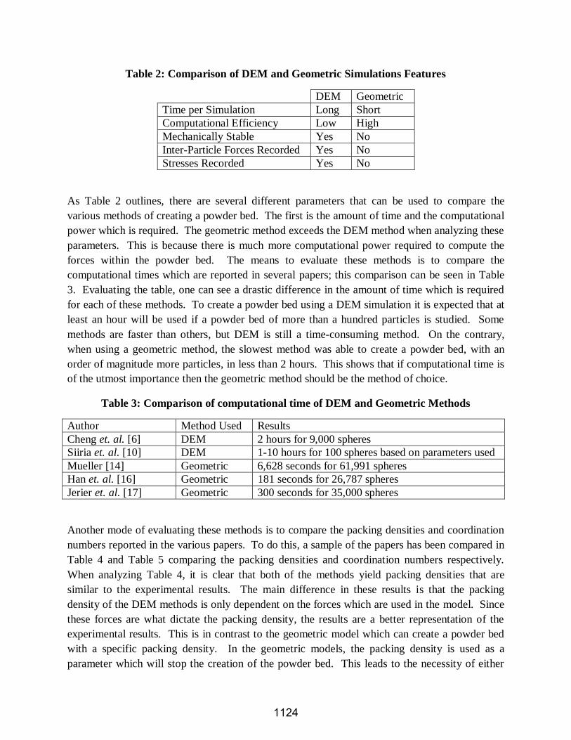
Table 2: Comparison of DEM and Geometric Simulations Features
DEM Geometric
Time per Simulation Long Short
Computational Efficiency Low High
Mechanically Stable Yes No
Inter-Particle Forces Recorded Yes No
Stresses Recorded Yes No
As Table 2 outlines, there are several different parameters that can be used to compare the
various methods of creating a powder bed. The first is the amount of time and the computational
power which is required. The geometric method exceeds the DEM method when analyzing these
parameters. This is because there is much more computational power required to compute the
forces within the powder bed. The means to evaluate these methods is to compare the
computational times which are reported in several papers; this comparison can be seen in Table
3. Evaluating the table, one can see a drastic difference in the amount of time which is required
for each of these methods. To create a powder bed using a DEM simulation it is expected that at
least an hour will be used if a powder bed of more than a hundred particles is studied. Some
methods are faster than others, but DEM is still a time-consuming method. On the contrary,
when using a geometric method, the slowest method was able to create a powder bed, with an
order of magnitude more particles, in less than 2 hours. This shows that if computational time is
of the utmost importance then the geometric method should be the method of choice.
Table 3: Comparison of computational time of DEM and Geometric Methods
Author Method Used Results
Cheng et. al. [6] DEM 2 hours for 9,000 spheres
Siiria et. al. [10] DEM 1-10 hours for 100 spheres based on parameters used
Mueller [14] Geometric 6,628 seconds for 61,991 spheres
Han et. al. [16] Geometric 181 seconds for 26,787 spheres
Jerier et. al. [17] Geometric 300 seconds for 35,000 spheres
Another mode of evaluating these methods is to compare the packing densities and coordination
numbers reported in the various papers. To do this, a sample of the papers has been compared in
Table 4 and Table 5 comparing the packing densities and coordination numbers respectively.
When analyzing Table 4, it is clear that both of the methods yield packing densities that are
similar to the experimental results. The main difference in these results is that the packing
density of the DEM methods is only dependent on the forces which are used in the model. Since
these forces are what dictate the packing density, the results are a better representation of the
experimental results. This is in contrast to the geometric model which can create a powder bed
with a specific packing density. In the geometric models, the packing density is used as a
parameter which will stop the creation of the powder bed. This leads to the necessity of either
1124

performing DEM simulations or experiments to determine what values are appropriate for the
packing density to be used in the simulation.
Table 4: Comparison of packing densities of DEM and Geometric Methods
Author Method Used Results
Finney [18] Experimental Packing Density 0.636 (with particles of normal
distribution)
Deng et. al. [7] DEM Packing Density 0.65 (with particles of singular
diameter)
Siiria et. al. [10] DEM Highest Packing Density 0.55 (with particles of singular
diameter)
Shi et. al. [19] DEM Stable Packing Density 0.578 (with particles of normal
distribution)
Jerier et. al. [13] Geometric Packing Density 0.7-0.4 based on user inputs (with
particles of normal distribution)
Mueller [14] Geometric Packing Density 0.59-0.37 depending on ratio of
container height to particle diameter (with particles of
singular diameter)
Han et. al. [16] Geometric Packing Density 0.5289 (with particles of normal
distribution)
Table 5 compares the coordination numbers of the various methods. When reviewing a paper
such as [20], it becomes obvious that there are multiple different values which have been
reported in the literature. This has led to different results based on several parameters, the largest
factor is the material used. For this reason, the value of the DEM solutions are usually assumed
to be a more accurate estimate of the actual coordination number due to the method of the
powder bed generation. As can be seen from the data which is displayed in Table 5, the DEM
solutions produce a coordination number which is slightly smaller than that of the geometric
models. The difference in these simulations can be again attributed to the methods used to
generate the results. In the DEM simulation, the model is a more realistic representation of the
actual method of building a powder bed. This results in a bed which has a coordination number
more closely aligned with reality. In the geometric method, the coordination number can be
varied within the model by changing the initial parameters which determine when the program
will end. R.M. German in [20] reports that there can be a wide variance in the reported values
based on the material and other variables. Therefore, this parameter should be used as a decisive
factor with caution.
1125

Table 5: Comparison of coordination number of DEM and Geometric Methods
Author Method Used Results
Deng et. al. [7] DEM Coordination Number of 4-6 varying on Particle
diameter (10-1000um)
Shi et. al. [19] DEM Stable Packing Coordination Number 5.97
Jerier et. al. [13] Geometric Average Coordination Number 6
Jerier et. al. [17] Geometric Coordination Number 4.75-7.5 based on particle sizes
Due to the uniqueness of each model, various sectors of research rely on each of the models
differently. One area of study that relies heavily on DEM simulations is the concrete industry.
This area of research is very interested in the stresses that are felt by the particles of the concrete
which dictated the use of the DEM simulations to find the state of each particle. On the other
hand, for the use in modeling of powder beds for additive manufacturing it is usually only
necessary to obtain a proper density and coordination number for the powder bed. Therefore, in
most cases, the geometric method would be the best option because it is computationally cheap
and has a short time per simulation; which would allow for more time and computation power to
be spent on modeling of the thermal processes which are taking place within the system. The
main problem with the geometric models is they contain an induced coordination number. In the
modeling of the powder bed additive manufacturing systems this is crucial because the
coordination number is one of the key factors which dictate the flow of heat through the powder
bed. If a powder bed has a higher coordination number then heat will flow faster through the
system, since heat travels faster by conduction than convection. This problem can be mitigated
by selecting a geometric model which mimics the coordination numbers which are reported in
the literature from DEM simulations.
Other Models
There are a few other models which are not as commonly used as DEM and the geometric
method. These methods include, but are not limited to, the ballistic method powder bed
generation, and the Monte Carlo simulation of powder beds.
The ballistic method for creating a powder bed can be found in [21], [22] and others. This model
is a hybrid between the DEM and the geometric models. In this simulation a particle is selected
and given a random radius, and x-y coordinates and placed high above the container. It is then
moved down toward the powder bed until contact is made with either another particle or the
floor. If contact is made with the floor the particle is considered at its final location. If it hits a
particle then it is rotated about the place of contact until another contact is made. After this
contact, the particle is rotated about these two points of contact until a third contact is made.
This is then considered its final location. If the particle at any time contacts the floor or wall
during these rotation it is then considered to be in its final location. This method allows for a
much faster simulation than the DEM method and allows for a seemingly more random packing
1126

of the particles. Based on the literature presented in [22] and the results presented, this method
provides coordination numbers and porosities which are comparable to DEM simulation,
geometric simulations, and experimental results.
Another approach to creating a powder bed that has been shown in the literature [23] and [24] is
the use of Monte Carlo algorithms. Just as all of the other methods for powder bed creation this
method varies depending on the author. In general, this method begins with filling a domain
with a specific number of particles. These particles are given a random direction and distance to
move. This motion is considered valid if the particle does not come into contact with a wall or
another particle. This is considered a Monte Carlo step due to its use of random number
generators to find the path and length. This Monte Carlo step is then repeated a given number of
times. After the Monte Carlo steps are completed, the minimum distance between spheres is
found to be δ. The domain is then scaled down by a factor derived from δ and the simulation is
run again. This is method is completed until a specific packing density is created or the packing
density between steps does not change more than a given threshold.
Conclusion
In general, all of these methods have been used to create powder beds which have been validated
by experimental results. As was stated previously, the use of each method is dictated by the
results which are desired from the simulation. The main factor which will determine the method
used is the necessity of the contact forces. If these forces are required, then DEM is the only
method which can be used. If these forces are not essential, then computationally it would be
more efficient to use the geometric, ballistic, or Monte Carlo simulations. These last simulations
would be the best for modeling of additive manufacturing powder bed systems due to their low
computational time and accurate model. Overall, Table 2 can be used to help determine which
method is the best for any given situation.
References
[1] W. King, A. T. Anderson, R. M. Ferencz, N. E. Hodge, C. Kamath and S. A. Khairallah, "Overview of modeling and simulation of metal powder-bed fusion process at Lawrence Livermore National Laboratory," Materials Science and Technology, 2014.
[2] F. Liou, Z. Fan, K. Slattery, M. Kinsella, J. Newkirk and H.-N. Chou, "Modeling and Simulation of a Laser Deposition Process".
[3] G. Bugeda, M. Cervera and G. Lombera, "Numberical Prediction of temperature and density distrubutions in selective laser sintering processes," Rapid Prototyping Journal, vol. 5, no. 1, pp. 21-26, 1999.
[4] J. William and C. Deckard, "Advances in modeling the effects of selected parameters on the SLS process," Rapid Prototyping Journal, vol. 4, no. 2, pp. 90-100, 1998.
[5] P. S. O. Cundall, "A discrete numerical model for granular assembilies," Geotechnique, vol. 29, pp. 47-65, 1979.
[6] Y. F. Cheng, S. J. Guo and H. Y. Lai, "Dynamic simulation of random packing of spherical particles,"
1127
Powder Technology, vol. 107, pp. 123-130, 2000.
[7] X. L. Deng and R. N. Dave, "Dynamic simulation of particle packing influenced by size, aspect ratio and surface energy," Granular Matter, vol. 15, pp. 401-415, 2013.
[8] R. Y. Yang, R. P. Zou and A. B. Yu, "Computer simulation of the packing," Physical Review E, vol. 62, no. 3, pp. 3900-3908, 2000.
[9] K. L. Johnson, K. Kendall and A. D. Roberts, "Surface Energy and the Contact of Elastic Solids," Proceedings of the Royal Society of London. Series A, Mathematical and Physical, vol. 324, no. 1558, pp. 301-313, 1971.
[10] S. Siiria and J. Yliruusi, "Particle packing simulations based on Newtonian mechanics," Powder Technology, vol. 174, no. 3, pp. 82-97, 2007.
[11] K. Z. Y. Yen and T. K. Chaki, "A dynamic simulation of particle rearrangement in powder packings with realistic interactions," Journal of Applied Physics, vol. 71, no. 7, pp. 3164-3173, 1992.
[12] R. Y. Yang, R. P. Zou, A. B. Yu and S. K. Choi, "Characterization of interparticle forces in the packing of cohesive fine particles," Physical Review E, vol. 78, 2008.
[13] J.-F. Jerier, D. Imbault, F.-V. Donze and P. Doremus, "A geometric algorithm based on tetrahedral meshes to generate a dense polydisperse sphere packing," Granular Matter, vol. 11, pp. 43-52, 2009.
[14] G. E. Mueller, "Numerically packing spheres in cylinders," Powder Technology, vol. 159, pp. 105-110, 2005.
[15] W. S. Jodrey and E. M. Tory, "Computer simulation of close random packing of equal spheres," Physical Review A, vol. 33, no. 4, pp. 2347-2351, 1985.
[16] K. Han, Y. T. Feng and D. R. J. Owen, "Sphere packing with a geometric based compression algorithm," Powder Technology, vol. 155, pp. 33-41, 2005.
[17] J.-F. Jerier, V. Richefeu, D. Imbault and F.-V. Donze, "Packing spherical discrete elements for large scale simulations," Computer Methods in Applied Mechanics and Engineering, vol. 199, pp. 1668-1676, 2010.
[18] J. L. Finney, "The Geometry of Random Close Packing," The Royal Society, vol. 319, p. 479, 1970.
[19] Y. Shi and Y. Zhang, "Simulation of random packing of spherical particles with different size distrubutions," Applied Physics A, vol. 92, pp. 621-626, 2008.
[20] R. M. German, "Coordination number changes during powder densification," Powder Technology, vol. 253, pp. 368-376, 2014.
[21] N. D. Aparicio and C. F. Cocks, "On the representation of random packings of spheres for sintering simulations," Acta Metallurgica, vol. 43, no. 10, pp. 3873-3884, 1995.
[22] M. M. Roozbahani, B. B. K. Huat and A. Asadi, "The effect of different random number distributions on the porosity of spherical particles," Advanced Powder Technology, vol. 24, pp. 26-35, 2013.
[23] R. S. Maier, D. M. Kroll, R. S. Bernard, S. E. Howington, J. F. Peters and H. T. Davis, "Hydrodynamic dispersion in confined packed beds," Physics of Fluids, vol. 15, no. 12, pp. 3795-3815, 2003.
[24] C. R. Abreu, R. Macdias-Salinas, F. W. Tavares and M. Castier, "A Monte Carlo simulation of the packing and segreatrion of sphers in clyinders," Brazilian Journal of Chemical Enigeering, vol. 16, no. 4, 1999.
1128