modeling of reinforced concrete beams with and · pdf filemodeling of reinforced concrete...
TRANSCRIPT
Journal of Engineering Sciences, Assiut University, Vol. 37, No. 4, pp. 845-858, July 2009.
845
MODELING OF REINFORCED CONCRETE BEAMS WITH AND WITHOUT OPENING BY USING ANSYS
OSMAN M. RAMADAN1, SAYED M. ABDELBAKI2, AHMED M. SALEH3 AND ABDULKAREEM Y. ALKHATTABI4 1 Professor, Faculty of Engineering, Cairo University
2 Professor, National Housing and Building Research Center
3 Associate Professor, Faculty of Engineering, Cairo University
4 Graduate Student, Cairo University
(Received May 11, 2009 Accepted May 31, 2009)
This paper presents the procedures of constructing an ANSYS nonlinear
finite element model for reinforced concrete beam analysis. This model
was used to analyze reinforced concrete beams with and without
openings. The results were compared with the experimental results of full-
scale laboratory tests made experimentally. Beams strength, stiffness,
deformed shape, and cracking patterns were investigated. The comparison
between experimental and analytical results showed acceptable
agreement.
KEYWORDS: reinforced concrete, beams, web openings, shear, finite
elements, ANSYS
1. INTRODUCTION
The experimental tests of reinforced concrete members cost a lot of money, time and
effort. This was a reason of research limitation and made the study of all aspects a very
hard mission. These difficulties have been overcome by simulating reinforced concrete
members and analyzing them numerically. The finite element method was used to
construct an analytical model of reinforced concrete beams with and without openings.
The common finite element analysis software, ANSYS, was used to conduct this study.
The strength, stiffness and cracking pattern of analyzed beams were carefully
investigated. The results were compared with test results of full scale reinforced
concrete beams with same geometry and details manufactured and experimentally
tested by the authors.
2. FINITE ELEMENT METHOD
The Finite Element Method (FEM) involves dividing the complex domain into finite
elements and uses variational concepts to construct an approximation of the solution.
There are two types of analysis: 2-D modeling and 3-D modeling. A 2-D modeling is
simple, can be run on normal computers but may give less accurate results on some
applications. However, a 3-D modeling produces more accurate results while
sacrificing the ability to run effectively on all but the fastest computers. Within each of
these modeling schemes, numerous algorithms (functions) can be inserted to make the
system behave linearly or non-linearly. Linear systems are far less complex and

Osman M. Ramadan et al. 846
generally do not take into account plastic deformation. Non-linear systems do account
for plastic deformation, and many also are capable of analyze a material all the way to
fracture.
3. ANALYSIS COMPUTER PROGRAMS
A number of computer program packages have been developed for the solution of
finite element problems. Among the more widely used packages are ANSYS,
NASTRAN, ADINA, LS-DYNA, MARC, SAP, COSMOS, ABAQUS, and NISA. The
latest version of ANSYS, ANSYS11 multiphysics, was chosen to be used in this
research work. It is capable in modeling nonmetal materials and effective to model
reinforced concrete as a non-homogeneous material with nonlinear response. It has also
the capability to predict and display the patterns of cracking and crushing of the
material.
4. ANSYS FINITE ELEMENT MODEL
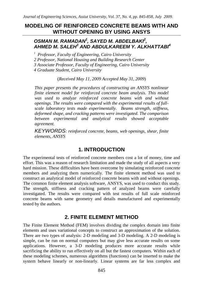
Modeling of reinforced concrete in ANSYS starts by choosing one of three methods
that can be used to model steel reinforcement in finite element models. These methods
are (Figure 1): 1) discrete method; 2) embedded method; and 3) smeared method.
In the discrete method, reinforcement is modeled using bar or beam elements
connected to the concrete mesh nodes. As a result, there are shared nodes between the
concrete mesh and the reinforcement mesh, as shown in Figure 1a. Also, since the
reinforcement is superimposed in the concrete mesh, concrete exists in the same
regions occupied by the reinforcement.
To overcome mesh dependency in the discrete model, the embedded
formulation allows independent choice of concrete mesh, as shown in Figure 1b. In the
embedded method, the stiffness of the reinforcing elements is evaluated independently
from the concrete elements, but the element is built into the concrete mesh in such a
way that its displacements are compatible with those of surrounding concrete elements.
That is, the concrete elements and their intersection points with each reinforcement
segment are identified and used to establish the nodal locations of the reinforcement
elements.
In the smeared method, it is assumed that reinforcement is uniformly spread
throughout the concrete element in a defined region of the finite element mesh. This
approach is used for large-scale models where the reinforcement does not significantly
contribution to the overall response of the structure (Figure 1c).
For this research work, the discrete method was chosen to model steel
reinforcement in the finite element model of reinforced concrete beam. The finite
element model itself can be created in ANSYS using command prompt line input, the
Graphical User Interface (GUI), or ANSYS Parametric Design Language (APDL).
APDL was used for creating the models in this paper.
MODELING OF REINFORCED CONCRETE BEAMS WITH AND…… 847
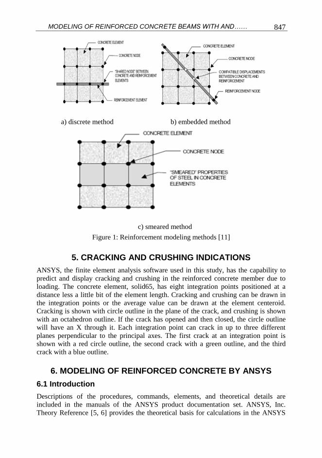
5. CRACKING AND CRUSHING INDICATIONS
ANSYS, the finite element analysis software used in this study, has the capability to
predict and display cracking and crushing in the reinforced concrete member due to
loading. The concrete element, solid65, has eight integration points positioned at a
distance less a little bit of the element length. Cracking and crushing can be drawn in
the integration points or the average value can be drawn at the element centeroid.
Cracking is shown with circle outline in the plane of the crack, and crushing is shown
with an octahedron outline. If the crack has opened and then closed, the circle outline
will have an X through it. Each integration point can crack in up to three different
planes perpendicular to the principal axes. The first crack at an integration point is
shown with a red circle outline, the second crack with a green outline, and the third
crack with a blue outline.
6. MODELING OF REINFORCED CONCRETE BY ANSYS
6.1 Introduction
Descriptions of the procedures, commands, elements, and theoretical details are
included in the manuals of the ANSYS product documentation set. ANSYS, Inc.
Theory Reference [5, 6] provides the theoretical basis for calculations in the ANSYS
a) discrete method b) embedded method
c) smeared method Figure 1: Reinforcement modeling methods [11]

Osman M. Ramadan et al. 848
program, such as elements, solvers and results formulations, material models, and
analysis methods to show how it uses the input data to calculate the output. It also
explains how to deduce results and describes the relationship between input data and
output results produced by the program. The program can account for concrete material
nonlinearity including cracking and crushing capability. Only the concrete element
(SOLID65) supports the concrete model. Plasticity theory provides a mathematical
relationship that characterizes the elasto-plastic response of materials. There are three
ingredients in the rate-independent plasticity theory: the yield rule criterion, flow rule,
and the hardening rule.
The yield criterion determines the stress level at which yielding is initiated. For
multi-component stresses, this is represented as a function of the individual
components, f({σ}), which can be interpreted as an equivalent stress σe:
σe= f({σ})
Where:
{σ} = stress vector
When the equivalent stress is equal to a material yield parameter σy, i.e.
σe=f({σ})= σy, the material will develop plastic strains. If σe is less than σy, the material
is elastic and the stresses will develop according to the elastic stress-strain relations.
Stress-strain behavior of multilinear isotropic plasticity option is shown in Figure 2.
The flow rule determines the direction of plastic straining. The hardening rule
describes the changing of the yield surface with progressive yielding. Two hardening
rules are available: work (or isotropic) hardening and kinematic hardening. In work
hardening, the yield surface remains centered about its initial centerline and expand in
size as the plastic strains develop (Figure 3a). For materials with isotropic plastic
behavior this is termed isotropic hardening. Kinematic hardening assumes that the
yield surface remains constant in size and the surface translates in stress space with
progressive yielding (Figure 3b). The Multilinear Isotropic Hardening (MISO)
plasticity option uses VonMieses/Hill yield criteria. Figure 4 shows the yield surfaces
for different material models.
6.2 Modeling Procedures
The discrete method, available in ANSYS, for modeling reinforced concrete is utilized.
In this method, solid elements with cracking, crushing and plasticity capabilities are
used to model concrete whereas link members with plasticity capability are used for
steel bars.
6.2.1 Element Types
Concrete was modeled in ANSYS by an eight-node solid element, Solid65, which has
eight nodes with three degrees of freedom per node: translations in x, y, and z
directions. This element has the capabilities of cracking, crushing and deforming
plastically. Steel reinforcement was modeled by a 3-D link element, Link8, which
needs two nodes and has three degrees of freedom for each node as translations in x, y
and z directions. The element is capable of plastic deformation. Steel plates were used
at support and loading points. These steel plates were modeled by eight-node solid
elements, Solid45. The geometry of elements type Solid 65, Link 8 and Solid45 are
shown in Figures 5a, 5b and 5c, respectively.

MODELING OF REINFORCED CONCRETE BEAMS WITH AND…… 849
Figure 2: Stress-strain behavior for plasticity options [7]
Figure 3:Hardening rules [7]

Osman M. Ramadan et al. 850
6.2.2 Material Properties
Concrete is defined as multi-linear isotropic material. The idealized stress-strain curves
for concrete and steel recommended by the Egyptian code [10] were utilized taking
γc=γs=1 and allowing concrete to resist some tensile stresses. The steel is defined by a
bilinear elastic-perfectly plastic stress-strain relation. The idealized stress-strain curves
for concrete and steel used are shown in Figures 6. The material constants for concrete
are as follows:
1. Concrete properties:
Shear transfer coefficient for open crack βop=0.3
Shear transfer coefficient for closed crack βcl=0.9
Ultimate uniaxial tensile strength-modulus of rapture
fctr= cuf6.0 =3 N/mm2
Figure 4:Yield surfaces [7]

MODELING OF REINFORCED CONCRETE BEAMS WITH AND…… 851
a) Solid65 b) Link8 c) Solid45
Figure 5: Geometry for utilized finite element types
Ultimate uniaxial compressive strength fcu =30 N/mm2
Modulus of elasticity Ec=24100 N/mm2
Poisson’s ratio for concrete νc=0.2
2. Reinforcing steel properties:
Initial modulus of elasticity Es=200000 N/mm2
Yield stress fy=360 N/mm2
Poisson’s ratio for steel νs=0.3
a) for concrete b) for steel
Figure 6: Idealized stress-strain curves used in analysis
6.2.3 Geometry
Taking advantage of symmetry of the beams about XY plane, only one half of the
beam was modeled. This reduces computational time and computer disk space
requirements. Nodes were constructed to produce concrete elements, link elements
Strain
Str
ess
0 0.001 0.002 0.003
0.8 fcu
Strain
Str
ess
fy
fy
y
y (+ve) (-ve)
cuf6.0
(+ve)
(+ve)
(-ve)
(+ve)
(-ve)
(-ve)

Osman M. Ramadan et al. 852
were then added on the existing nodes. Element dimensions for concrete and steel
plates were chosen to be 20×20×20 mm and 20×20×40 mm, whereas reinforcement bar
elements were chosen to be 20mm in length.
6.2.4 Solution
Each beam was loaded by a monotonically increasing load applied as a line load in the
middle of the steel plate located at the midspan of the top face as shown in Figure 7.
Proper displacement boundary conditions were applied on all nodes on the symmetry
plane. One support line was modeled as hinged support allowing rotation only while
the other was modeled as a roller support allowing both rotation and horizontal
translation.
7. MODELING VERIFICATION
The results of two full-scale reinforced concrete beams tested experimentally by the
authors were compared to the theoretical results obtained by analyzing same beams by
the above described ANSYS model. Both beams had a span of 2200mm, a width of
120mm, and a total of 320mm. Beam B1 was without opening while beam B2 was
with an opening 360×80 mm in the shear span of it. The geometrical and reinforcement
details are shown in Figures 7 and 8.
Experimental and theoretical results of the beams B1 and B2 were compared to
verify the accuracy of the modeling. The tested beams were prepared from local
materials and tested under a monotonically increasing load at its midspan till failure.
Full details of the experimental program as well as theoretical investigation can be
found elsewhere [4].
3ø16
2ø10
P
5ø6/m
Steel Plate80x120x20
Steel Plate160x120x30
A
A
Sec. A-A 300 320
120
2480
140 2200 140
2ø10
5ø6/m 3ø16
Figure 7: Details of beam B1

MODELING OF REINFORCED CONCRETE BEAMS WITH AND…… 853
2200
3ø16
2ø10
3ø16
2ø10B
B
P
5ø6/m
5ø6/m
Steel Plate80x120x20
Steel Plate160x120x30
140
3ø16
2ø10
2ø10
2ø10
A
A
Sec. A-A Sec. B-B
300 320
2x2ø10
120120
2480
300 320
5ø6/m
5ø6/m
5ø6/m
140
t
x
to
360
Figure 8: Details of beam B2
7.1 Beam B1
Load deflection curves obtained both experimentally and numerically are shown in
Figure 9. Experimental and numerical deflection lines along beam span at different
load levels are shown in Figure 10. The failure modes for beam B1 are compared in
Figure 11.
0
20
40
60
80
100
120
140
0 2 4 6 8 10 12 14 16
Deflction at midspan (mm)
Lo
ad
(k
N)
Numerical
Experimental
Figure 9: Load deflection curve for beam (B1)

Osman M. Ramadan et al. 854
0
1
2
3
4
5
6
7
8
9
10
0 550 1100 1650 2200
Beam span (mm)
De
flecti
on
(m
m)
14 kN theo
14 kN exp
49 kN theo
49 kN exp
117.72 kN theo
117.72 kN exp
Figure 10: Deflection lines for beam (B1)
(a)
(b)
Figure 11: Failure mode: a) Experimental; b) Numerical
As seen from Figures 9 and 10, the numerical simulations produce close
behavior to the experimental measurements up to about 70% of the ultimate load.
Then, the model predicts a stiffer behavior and a higher strength. The cracking and
crushing patterns shown in Figure 11 are reasonably close. The observed stiffening
effect can be attributed to the constant shear retention factor used throughout the
loading history. This is clearly not the case in reality where shear transfer across cracks
deteriorates with increasing crack width.

MODELING OF REINFORCED CONCRETE BEAMS WITH AND…… 855
7.2 Beam B2
Figure 12 compares the load deflection curves obtained experimentally to the
numerically calculated one. Also the experimental and numerical deflection lines along
beam span at different load levels are shown in Figure 13. Finally, Figure 14 presents
the failure modes of the tested beams and its theoretical prediction. The comparison
between numerical and experimental results for beam (B2) leads to similar conclusions
as discussed above for beam (B1). It is therefore concluded that the adopted modeling
is capable of close representation of the actual beams.
0
20
40
60
80
100
120
140
0 2 4 6 8 10 12 14 16
Deflection at midspan (mm)
Lo
ad
(kN
)
Numerical
Experimental
Opening 360x80 @ 480mm
Figure 12: Load deflection curve for beam (B2)
0
1
2
3
4
5
6
7
8
9
10
0 550 1100 1650 2200Beam span (mm)
defl
ecti
on
(m
m)
24.5 kN theo
24.5 kN exp
58.8 kN theo
58.8 kN exp
107 kN theo
107.8 kN expOpening
Figure 13: Deflection lines for beam (B2)

Osman M. Ramadan et al. 856
8. RESULTS SUMMARY
The results are summarized in this section. Table 1 contains the experimental and
theoretical values of cracking load, failure load and corresponding deflection values.
Table 1: Comparison between Experimental and Theoretical Results
B1 B2
At first
crack
Load (kN)
Experimental 24.5 14.7
Theoretical 20.7 13.6
Deviation 16% 8%
Deflection (mm)
Experimental 0.88 0.51
Theoretical 0.53 0.36
Deviation 40% 30%
At failure
Load (kN)
Experimental 127.5 107.8
Theoretical 149.0 107.0
Deviation 14% 1%
Deflection (mm)
Experimental 16.9 8.8
Theoretical 15.8 6.3
Deviation 14% 29%
9. CONCLUSIONS
The nonlinear behavior of reinforced concrete beams can be simulated by the three
dimensional ANSYS modeling. The analysis of reinforced concrete members by finite
elements method and ANSYS computer program could save a lot of money, time and
effort and give a chance to study aspects which was hard to be conducted in the
experimental studies. Based on the analysis of the experimental and theoretical results,
the following remarks can be made:
(a)
(b)
Figure 14: Failure mode of B2: a) Experimental; b) Numerical

MODELING OF REINFORCED CONCRETE BEAMS WITH AND…… 857
1. Detailed theoretical background and procedures of preparing a nonlinear finite
element ANSYS model for reinforced concrete beam, with and without openings
were presented.
2. The comparison between the experimental and theoretical results with respect to
strength, stiffness, deformed shape and cracking patterns showed satisfactory
agreement.
3. For the analyzed beams, the presence of opening decreased the beam initial and
ultimate strengths by 40% and 20%, respectively. At the same time, the stiffness was
decreased by 20%. The maximum deflection point was shifted a little bit to the side
of the opening because of the presence of the opening.
Finally, the finite element model verified in this paper can now be used in
additional studies to investigate the effect of the change in the opening dimension and
location in the reinforced concrete beam and also to study enhancement solutions such
as increasing stirrups or using diagonal bars around the opening etc.
REFERENCES
1. Abdalla, H. A.; Torky, A. M.; Haggag H. A.; and Abu-Amirah, A.F. (2003),
"Design Against Cracking at Openings in Reinforced Concrete Beams
Strengthened with Composite Sheets",Composite Structures, No. 60, pp.197-204.
2. ACI Committee 318 (2007), "Building Code Requirements for Reinforced concrete
(ACI 318-2007) and Commentary (ACI 318R-2007)", American Concrete
Institute, Detroit, USA.
3. Abu-Amirah, A. F. M. (2003), “Strengthening of Reinforced Concrete Beams with
Openings Using FRP Sheets”, Cairo University, Giza, Egypt.
4. Al Khattabi, A. Y., (2009), “Openings in Reinforced Concrete Beams
(Experimental Study and Theoretical Analysis)”, PhD Thesis, Cairo University,
Giza, Egypt (to appear).
5. Al-Shaarbaf, I. A. S., Al-Bayati, N. A-M. J., (2007), “Nonlinear Finite Element
Analysis of Reinforced Concrete Beams with Large Opening under Flexure”. Eng.
& Technology, vol.25, No.2, Baghdad, Iraq, pp. 210-228.
6. ANSYS Inc. (2006), "ANSYS Multiphysics-Finite Element Analysis Software-
Version 11.0" Canonsburg, Pennsylvania, USA.
7. ANSYS (2006), ANSYS user's Manual Revision 11.0, ANSYS Inc., Canonsburg,
Pennsylvania, USA.
8. Chen, W., F., “Plasticity in Reinforced Concrete”, McGraw-Hill, Inc., USA,
(1982).
9. Ding, W. Q.; Yue, Z. Q.; Tham, L. G. Zhu, H. H.; Lee, C. F. and Hashimoto, T.
(2004) “Analysis of shield tunnel”, Inter. J. for Numerical and Analytical Methods
in Geomechanics, Vol. 28, Issue 1, P: 57-91.
10. Egyptian Code for Design and Construction of Reinforced Concrete Structures
ECCS 203-2007, Cairo, Egypt.
11. Hamdy, M. W. O. (1991), “Effect of Openings Shapes at the Shear Span on the
Behavior of Prestressed Beams”, MSc. Thesis, Ain Shams University.
12. Kachlakev, D. I. (2002), “Finite Element Analysis and Model Validation of Shear
Deficient Reinforced Concrete Beams Strengthened with GFRP Laminates”, Paper

Osman M. Ramadan et al. 858
002, Third International Conference on Composites in Infrastructure, San
Francisco, California, June 10-12.
13. Mansur, M.A.; Huang, L. M.; Tan, K. H.; and Lee, S. L. (1992), "Deflection of
Reinforced Concrete Beams with Web Openings", ACI Structural Journal, V. 89
No. 4, July-Aug., pp. 391-397.
14. Mansur, M.A.; and Tan, K. H., "Concrete Beams with Openings: Analysis and
Design", CRC Press LLC, Boca Raton, Florida, USA, (1999), 224pp.
15. Masti, k., Maghsoudi, A. A., and Rahgozar, R., (2008), “Nonlinear Models and
Experimental Investigation of Lifetime History of HSC Flexural Beams”,
American journal of Applied Science 5 (3), USA, pp 248-262.
16. Nasser, K. W.; Acavalos, A.; and Daniel H. R. (1967), "Behavior of Large
Openings in Reinforced Concrete Beams", ACI Structural Journal, V. 64, No. 3,
January, pp. 25-33.
17. Ramadan, O.M.O. and Kansouh, H. (2007). ” Openings in Pure Bending Zone of
High Strength Concrete Beams," Engrg. Res. J., Fac. of Engrg., Helwan Univ., 112,
August, pp C14-C35.
18. Ramadan, O.M.O. and Kansouh, H. (2006). ” Openings in Pure Bending Zone of
HSC Beams," Scientific Bulletin, Faculty of Engineering, Ain-Shams University,
Vol. 41(3), pp 93-109.
19. Tan, K. H.; and Mansur, M.A. (1996), "Design Procedures for Reinforced
Concrete Beams with Large Web Openings", ACI Structural Journal, V. 93 No. 4,
July-Aug., pp. 404-411.
(ANSYS) نمذجة التحليل اإلنشائي لكمرات الخرسانة المسلحة باستخدام
نِّ تحليل عناصر الخرسانة المسلحة بطريقة العناصر المحددة يوفر الكثير من الوقت والجهد والمال إكونه اختبار غير مكلف وغير متلف ويعطي نتائج مقبولة وبه يمكن دراسة جوانب لم يكن من السهل
يًا. ويفصل هذا البحث خطوات إعداد نموذج لتحليل كمرات الخرسانة المسلحة باستخدام إجرائها معملالقص. وتطبيق ذلك على كمرتين من الخرسانة المسلحة في إحداهما فتحة في منطقة ANSYSبرنامج
القدرة على تمثيل الخرسانة كمادة غير متجانسة وتسلك سلوكًا ال خطيًا ANSYSحيث أن لبرنامج ستخدم ف في حالة إجهادات الشد بشكل يختلف عن تصرفها في حالة إجهادات الضغط، وقد اوتتصر
لتمثيل أسياخ صلب التسليح. أجري تحليل Link8لتمثيل الخرسانة والعنصر Solid65العنصر الكمرات على أنها ترتكز ارتكازا بسيطا على لوحين من الصلب عند نقطتي االرتكاز وتحت تأثير حمل
متزايد ومركز عند منتصف بحر الكمرة على لوح مماثل من الصلب وقد أدرج تمثيل ألواح الصلب ساكن أيضا ضمن النموذج.
قورنت نتائج التحليل بهذا النموذج مع نتائج اختبار معملي أجراه المؤلفون على كمرتين من الخرسانة منطقة القص ودرس تأثير تواجد الفتحة المسلحة باألبعاد الكاملة إحداهما بدون فتحة واألخرى بفتحة في
على سلوك كمرات الخرسانة المسلحة من حيث مقاومة األحمال ومقاومة التشكل وشكل الشروخ ونوع االنهيار وقد بينت المقارنة تقاربا مقبواًل.