modellaustausch in der kraftfahrzeugindustrie mit vhdl...
TRANSCRIPT
2. Aachen Electronics Symposium 2004
Modellaustausch in der Kraftfahrzeugindustrie mit VHDL-AMS - Vorgehensweise und Beispiele Model Exchange Process in Automotive Industry with VHDL-AMS – Philosophy and Examples Dipl.-Ing. Ewald Hessel Dr.-Ing. Alexander Graßmann Hella KGaA Hueck & Co. Lippstadt Intedis GmbH & Co. KG Würzburg
Dr.-Ing. Joachim Haase Dipl.-Ing. Jürgen Schäfer Fraunhofer-IIS/EAS Dresden CISC Semiconductor Klagenfurt
Abstract
VHDL-AMS is a standardized language to model and simulate digital, analog, and mixed-signal systems. Major German car manufactures and suppliers are checking the suitability of the language for real world heterogeneous automotive systems in the VDA/FAT Working Group “Simulation of Mixed Systems with VHDL-AMS” (Verband der Automobilindustrie/Forschungsvereinigung Automobiltechnik Arbeits-kreis AK 30). First experiences and results concerning the development of model libraries and simulation of electrical automotive systems are presented.
1 Introduction
Innovation cycles in automotive industry have become shorter and shorter during the last ten years accompanied by increased complexity of systems. For this reason simulation has become a standard method within the process of product development. To reduce costs and time, an easy model exchange between manufacturers and suppliers based on a standardized language is necessary. Therefore the SAE organization has developed the “Model Specification Process Standard J2546” [1], which describes model exchange as part of the product specification process. Besides this the IEEE standard 1076.1 (VHDL-AMS [2]) provides the means to describe behavioral models of components, subsystems and systems in a well defined manner and independent from any specific simulation tools.
2 Requirements Concerning Model Exchange in Automotive Industry
During the last three years the main task of the VDA/FAT Working Group “Simulation of Mixed Systems with VHDL-AMS” (VDA/FAT-AK30) consisting of major car manufacturers and suppliers in Germany was to check the suitability of VHDL-AMS for real world heterogeneous automotive systems. Therefore the working group has
2 2. Aachen Electronics Symposium 2004
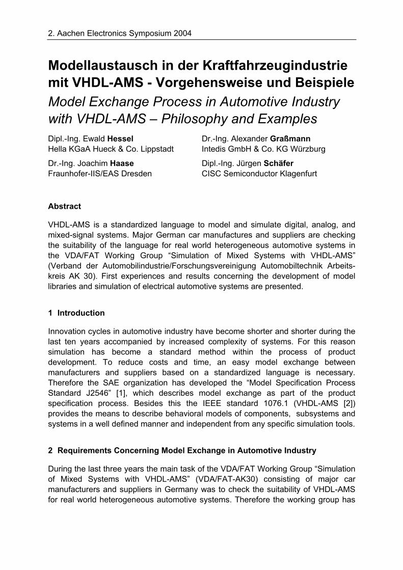
started pilot projects which focus on mixed-signal nature (time/value continuous combined with time/value discrete) using examples from different fields, power network (14V automotive powernet), communication network (LIN communication bus) and mechatronic (X-by-wire system).
Fig. 1: Model exchange process
The first results of this pilot projects are an optimized process for model exchange (Fig. 1) between car manufacturers and suppliers and the definition of a necessary language subset of VHDL-AMS that is supported by all relevant EDA vendors. Requirements for the development of consistent models were fixed.
These results are the base for the further working packages. Next steps for the integration of this process into industrial projects will be the offering of special VHDL-AMS model libraries for VHDL-AMS and the introduction of VHDL-AMS into existing development flows. For this purpose the working group has started different activities.
Since SPICE at this moment is the standard simulator for electronic simulations on PCB design level, there are a lot of simulation models for electronic devices. In order to use these models in system simulations based on VHDL-AMS the working group has developed a package for VHDL-AMS supporting models and functions equivalent to the basic models of Berkeley SPICE 3F5. A second library called FUNDAMENTALS_VDA has been created including fundamental models for different domains (electrics/electronics, mechanics, fluidics, thermics), generic models of integrated circuits (IC), control blocks, sources, and converters between different domains. In a further project the working group will establish an automotive specific library AUTOMOTIVE_VDA. This project is a research project funded by the FAT organization and started in July this year. The library will contain system level models of actuators, sensors, wire-lines, fuses and batteries and will be for free.
Component
OEM
Integration
Component Supplier
Technology Function
Integration
ECU Manufactor
OEM
2. Aachen Electronics Symposium 2004
3 Library Development
3.1 Behavioral Modeling Language VHDL-AMS
VHDL 1076.1 is informally known as VHDL-AMS. The abbreviation stands for VHSIC (Very High Speed Integrated Circuit) Hardware Description Language Analog and Mixed-Signal. VHDL-AMS provides language constructs for the hierarchical modeling and simulation of continuous and mixed-continuous/discrete systems. Different modeling methods and levels of abstraction in electrical and non electrical energy domains are supported. Description with signal flow diagrams is possible as well as the usage of lumped networks and state machines. The digital behavior is evaluated by an event-driven simulation algorithm. The analog behavior is simulated by solving differential algebraic equations. The definition of the mixed analog-digital simulation cycle is part of the language reference manual. Support for time and frequency analysis is provided. Since its standardization in 1999 by the IEEE numerous EDA vendors have made available VHDL-AMS simulation programs.
The powerful modeling capabilities, the integration into the design flow of electrical systems, the stable standardization process, and the widely support by commercial tools brought about the decision to use VHDL-AMS as language for the model exchange.
3.2 Organization of the Model Development
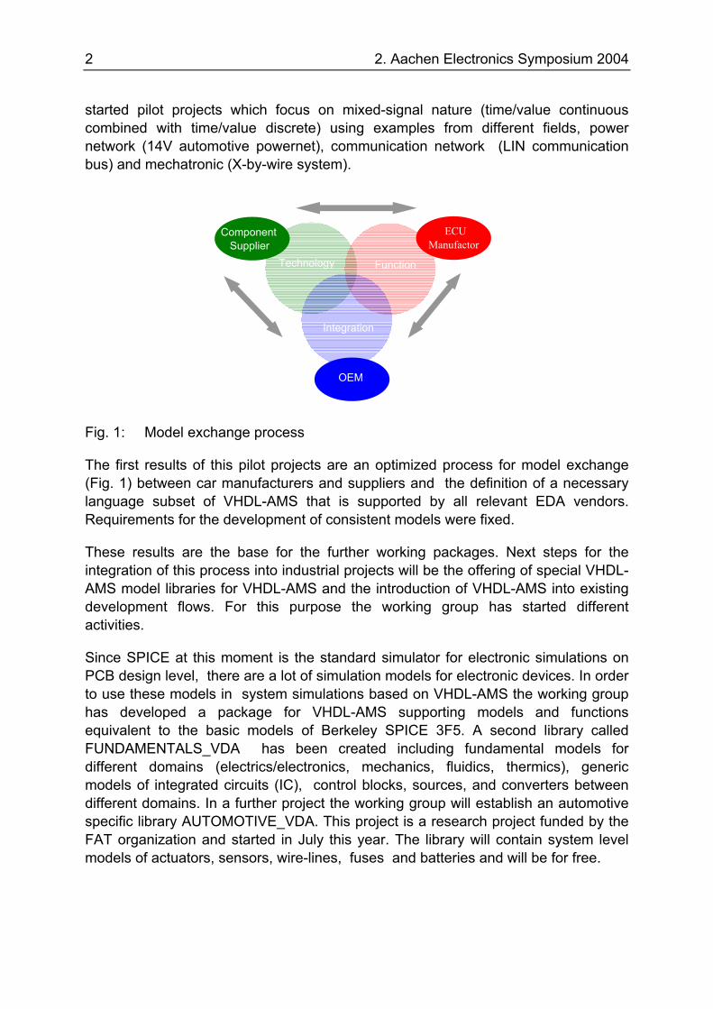
Fig. 2: Access to model documentation
MT_2MT_1
4 2. Aachen Electronics Symposium 2004
VHDL-AMS supports block level modeling. The interface of a subsystem is described by the so-called entity declaration that determines generic parameters and connection points. It defines the external view of a model that has to be documented carefully. The functionality of a subsystem is described by its architecture.
In order to allow for the combination of models of different origin, some agreements concerning the model development process had to be made. Among other things they pertain to:
• Interoperability of models, especially a uniform orientation for associated reference directions for across and through quantities (see also [3])
• Modeling style guide to ensure a unified appearance of the models, especially a uniform structure of models and comments in order to allow the automatic construction of the documentation
• Consideration of the different coverage of the VHDL-AMS standard by different tools
In general, the parameters of the models are based on datasheets. The language VHDL-AMS does not support a unit check. The user of models is responsible for the correct use of units. The documentation has to be done carefully. SI units are preferred. Temperatures shall be given in degree Kelvin.
The documentation is generated automatically. Starting point is the VHDL-AMS source code that fulfils specified requirements. The code is parsed and converted into an XML (Extensible Markup Language) document based on a project-specific document type definition (DTD) [4]. Using appropriated style sheets the XML files can be represented using a normal browser. Fig. 2 gives an example. The documentation includes the name of the logical library where the model has to be compiled into. Among other things it describes names, types, default values and units of generic parameters and names, types or nature of ports. Furthermore, the dependencies of a model on other logical libraries and design units or entities are recorded. The electronic documentation also allows for access to the source code of a model. Electronic documentation of the test cases will be made available in the near future.
The models are stored in a special file structure that corresponds to the logical VHDL-AMS libraries introduced in the previous section. For each model there exist subdirectories that contain the source code, test benches, symbols and the documentation. For development purposes the models are saved in a Subversion repository [5]. This facilitates the joint work of developers in different companies with more or less stringent safety requirements. The definition of a symbol format is in progress. It will build a bridge to different schematic entry tools and can also be used for documentation purposes.
2. Aachen Electronics Symposium 2004
4 Modeling Examples
4.1 Automotive Powernet
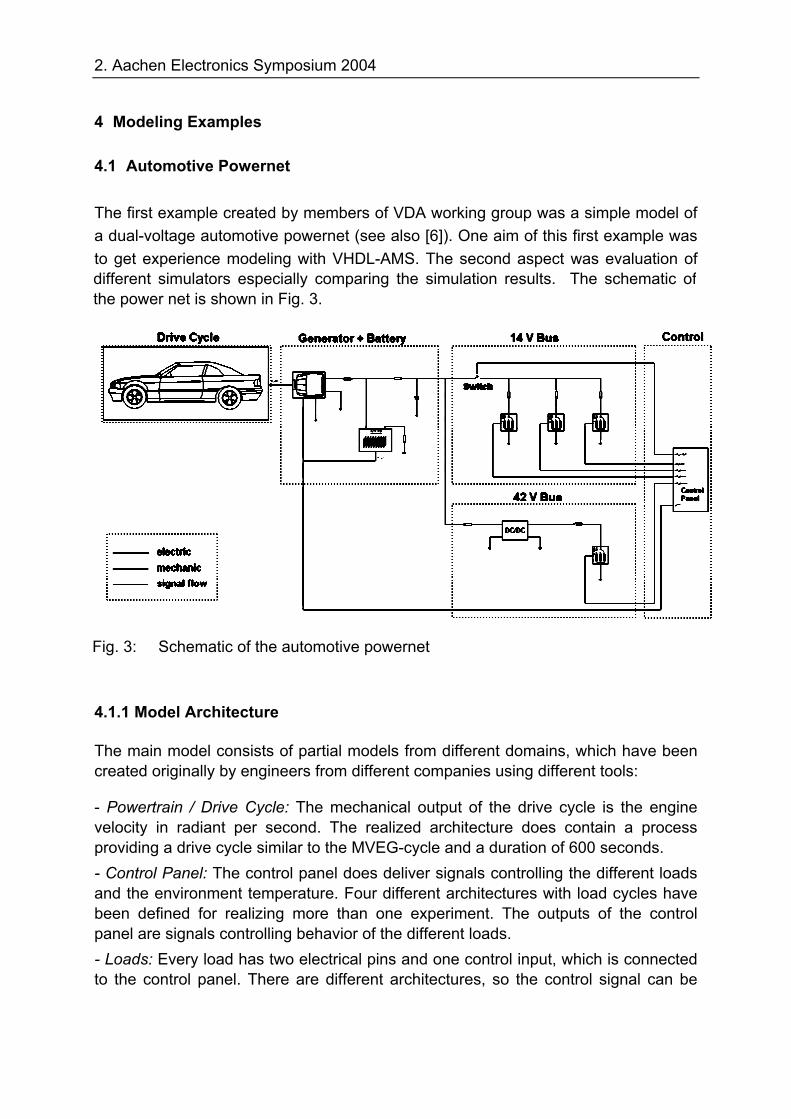
The first example created by members of VDA working group was a simple model of a dual-voltage automotive powernet (see also [6]). One aim of this first example was to get experience modeling with VHDL-AMS. The second aspect was evaluation of
4.1.1 Model Architecture
The main model consists of partial models from different domains, which have been created originally by engineers from different companies using different tools:
- Powertrain / Drive Cycle: The mechanical output of the drive cycle is the engine velocity in radiant per second. The realized architecture does contain a process providing a drive cycle similar to the MVEG-cycle and a duration of 600 seconds. - Control Panel: The control panel does deliver signals controlling the different loads and the environment temperature. Four different architectures with load cycles have been defined for realizing more than one experiment. The outputs of the control panel are signals controlling behavior of the different loads. - Loads: Every load has two electrical pins and one control input, which is connected to the control panel. There are different architectures, so the control signal can be
Fig. 3: Schematic of the automotive powernet
different simulators especially comparing the simulation results. The schematic ofthe power net is shown in Fig. 3.
6 2. Aachen Electronics Symposium 2004
either the value of an admittance or the percentage of the nominal power or an on/off signal. A more detailed model is available only for a lamp. - Battery: The battery model is very simple and does contain two resistors and two capacitors only. - Generator: The generator model does consist of a belt drive, a regulator, an electrical machine and a rectifier. It has one mechanical input connected to the power train, a temperature input and two electrical pins, one connected to the 14V bus and the other connected to ground. The generator has been modeled as a voltage controlled current source. The regulator compares the voltage of the 14V bus with the temperature dependent nominal voltage. Its output is the DF-signal that also shows the utilization of the generator. The value of the DF-signal is between 0 (no output current) and 1 (maximum output current). For the sake of load dump protection the gradient is limited by a first-order lag with a time constant of 0.3 seconds. The output current of the electrical machine is the DF-signal multiplied with the maximum output current. It is limited by a characteristic curve showing the dependence of the maximum current from temperature and rotational velocity at the belt drive. - DC/DC Converter: The idea behind the DC/DC converter is a tank for electrical energy. It is charged by a limited input current from the 14V bus. For the 42V bus, the converter is a current source getting the energy out of the tank. The converter tries to uphold the voltage level of the 42V bus with the help of a PI-controller. Altogether, the example consists of 27 entities and 32 architectures with 21 processes, 45 equations including 10 ordinary differential equations and 6 non-linear functions (nearly 1600 lines of code).
4.1.2 Experiments
As mentioned above, four different architectures for the control-panel with different load cycles are defined. These architectures do not contain any functions to avoid numerical problems, so all loads must do this for themselves. For all load architectures used the value of the control input is filtered and has a PT1 behavior with a time constant of 10µs. Within the powertrain architecture the gradient of the output velocity is limited by the implicit ‘ramp function, so every change takes one second.
To evaluate the whole example seven different simulation runs were done. The first experiment uses a 90A generator with small loads only at the 14V bus and no DC/DC converter. The results are as expected: Sometimes the generator can supply all the current needed, sometimes the battery must add some current, but during the whole experiment the voltage level at the 14V bus is above 12V. For the second experiment a few high-current peaks are added. During these peaks the voltage falls below 10V because of the load dump protection of the generator and the small battery used in this experiment. For the third simulation run the current at the 14V bus during the
2. Aachen Electronics Symposium 2004
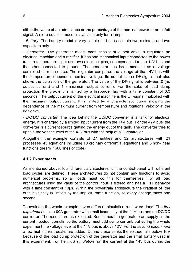
whole experiment is too high. The results of the simulations are as expected: The generator has maximum utilization, but it is not sufficient to hold the voltage level above 12V, especially during the idle periods of the engine. For experiment 4 a bigger 150A generator is used, but this is still not enough during the idle periods. Therefore, in experiment 5 the gear ratio of the belt drive has been increased from 2.5 to 3.0 (i.e., the generator revolutions increase accordingly). Now, the output current is sufficient even during the idle periods. Finally, for the simulation runs 6 and 7 a 42V bus and a DC/DC converter are added. In experiment 6 the input current of the converter is limited to 25A. This is too small, so the voltage at the 42V bus sometimes falls down to 30V. In experiment 7 the maximum input current is 60A, so that the voltage is above 36V during the whole simulation. As an example the results of simulation run 7 are shown in Fig. 4. The bottom curve represents the engine velocity, above is the DF-signal that describes the utilization of the generator,
It can be seen, that during idle times of the engine the generator utilization is 100% and the voltage at the 14V bus drops a little bit. At the beginning of the simulation there is a voltage rise to the nominal level. This is a consequence of the load dump protection: Initially only the battery supplies the 14V bus, then the generator output increase from 0A to the needed current delayed by a first-order lag. You can also see peaks at the 42V bus: At these points a load at the 42V bus is either switched on or off. The only capacity for the bus is inside the DC/DC converter, with an additional capacity, e.g. a battery, the peaks can be reduced.
For all experiments the qualitative behavior of the simulation and the results are as expected. Even if the models are simple and the quantitative results might not fit exactly reality, the conclusion is, that this model structure with models created in VHDL-AMS can be used for the general design of an automotive powernet.
and the top two curves show the voltage at the 14V and 42V bus
Fig. 4: Simulation results of experiment 7
8 2. Aachen Electronics Symposium 2004
4.2 Physical Layer Simulations of a LIN-Bus Network
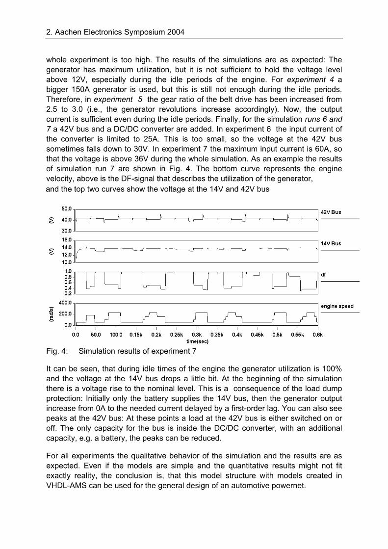
This reference project was started three years ago. The goal was to investigate the feasibility of VHDL-AMS in mixed-signal automotive systems. LIN (Local Interconnect Network) is a single wire field bus topology which is standardized by the ISO standardization organization. A LIN node contains two essential parts (Fig. 5). The first part is the protocol engine and the second part is the transceiver. The protocol engine can be implemented as a software routine or as a physical state machine. Both kinds of the implementation work on a microcontroller. The transceiver is the interface between the LIN protocol and the physical bus topology. According to the “ISO/OSI seven layer model” the transceiver is the connection between protocol layer and physical layer. Furthermore the transceiver protects the bus topology against physical errors like short circuit and high temperature.
Fig. 5: LIN node
Today in a lot of automotive comfort applications like air-condition or infotainment systems the LIN-bus is used as a communication interface for the associated ECUs (Electronic Control Unit) and the dashboard. As single wire bus the LIN topology can't be used for safety applications like breaking systems but for comfort applications the LIN-bus is the tradeoff between costs and functionality.
The goals of this project were the modeling of the LIN transceiver TLE6259 and the simulations within a complex LIN network. Therefore, the transceiver was modeled as mixed-signal VHDL-AMS model in a physical layer system level. To investigate the behavior of this model the LIN protocol engine has been described in a functionality level only and the wire lines of the bus are modeled in a structural description (RLC model). In addition to this main project goal we investigated
• the model exchange process between semiconductor supplier and OEM,
• the portability of VHDL-AMS code in different simulators without adaptation of the source code,
• the supported VHDL-AMS language set on the different simulators.
The system level model of the LIN transceiver is optimized for the tradeoff between accuracy, simulation performance, and numerical stability. For this reason a modeling method is used which describes the system relevant input and outputs as physical
Microcontroller (LIN protocol)
LIN transceiver txd en rxd
LIN- bus
2. Aachen Electronics Symposium 2004
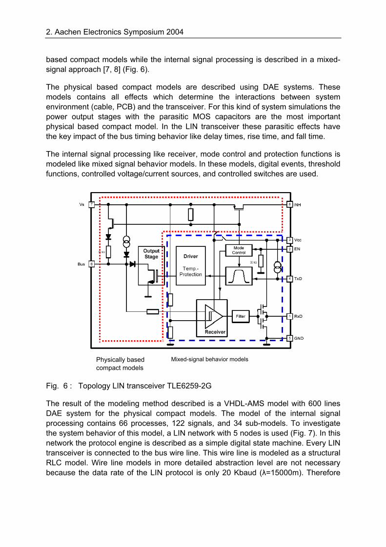
based compact models while the internal signal processing is described in a mixed-signal approach [7, 8] (Fig. 6).
The physical based compact models are described using DAE systems. These models contains all effects which determine the interactions between system environment (cable, PCB) and the transceiver. For this kind of system simulations the power output stages with the parasitic MOS capacitors are the most important physical based compact model. In the LIN transceiver these parasitic effects have the key impact of the bus timing behavior like delay times, rise time, and fall time.
The internal signal processing like receiver, mode control and protection functions is modeled like mixed signal behavior models. In these models, digital events, threshold functions, controlled voltage/current sources, and controlled switches are used.
Fig. 6 : Topology LIN transceiver TLE6259-2G
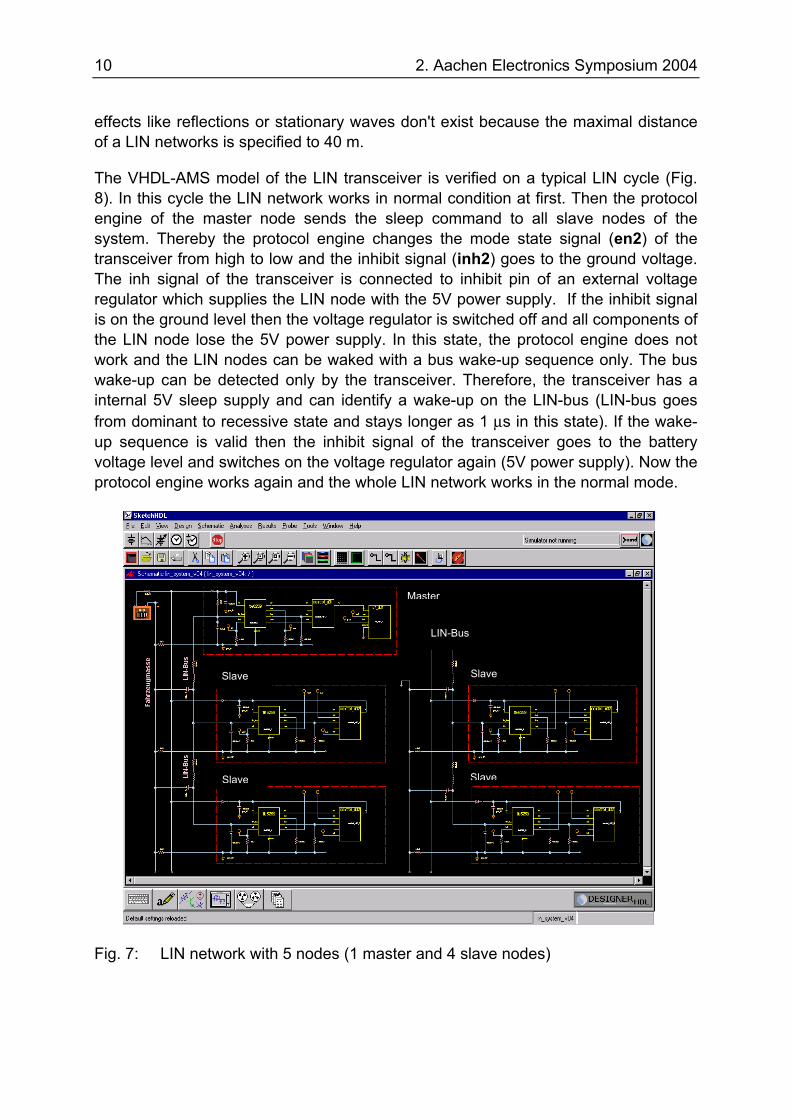
The result of the modeling method described is a VHDL-AMS model with 600 lines DAE system for the physical compact models. The model of the internal signal processing contains 66 processes, 122 signals, and 34 sub-models. To investigate the system behavior of this model, a LIN network with 5 nodes is used (Fig. 7). In this network the protocol engine is described as a simple digital state machine. Every LIN transceiver is connected to the bus wire line. This wire line is modeled as a structural RLC model. Wire line models in more detailed abstraction level are not necessary because the data rate of the LIN protocol is only 20 Kbaud (λ=15000m). Therefore
Physically based compact models
Mixed-signal behavior models
10 2. Aachen Electronics Symposium 2004
effects like reflections or stationary waves don't exist because the maximal distance of a LIN networks is specified to 40 m.
The VHDL-AMS model of the LIN transceiver is verified on a typical LIN cycle (Fig. 8). In this cycle the LIN network works in normal condition at first. Then the protocol engine of the master node sends the sleep command to all slave nodes of the system. Thereby the protocol engine changes the mode state signal (en2) of the transceiver from high to low and the inhibit signal (inh2) goes to the ground voltage. The inh signal of the transceiver is connected to inhibit pin of an external voltage regulator which supplies the LIN node with the 5V power supply. If the inhibit signal is on the ground level then the voltage regulator is switched off and all components of the LIN node lose the 5V power supply. In this state, the protocol engine does not work and the LIN nodes can be waked with a bus wake-up sequence only. The bus wake-up can be detected only by the transceiver. Therefore, the transceiver has a internal 5V sleep supply and can identify a wake-up on the LIN-bus (LIN-bus goes from dominant to recessive state and stays longer as 1 µs in this state). If the wake-up sequence is valid then the inhibit signal of the transceiver goes to the battery voltage level and switches on the voltage regulator again (5V power supply). Now the protocol engine works again and the whole LIN network works in the normal mode.
Fig. 7: LIN network with 5 nodes (1 master and 4 slave nodes)
Master
Slave
Slave
Slave
Slave
LIN-Bus
2. Aachen Electronics Symposium 2004
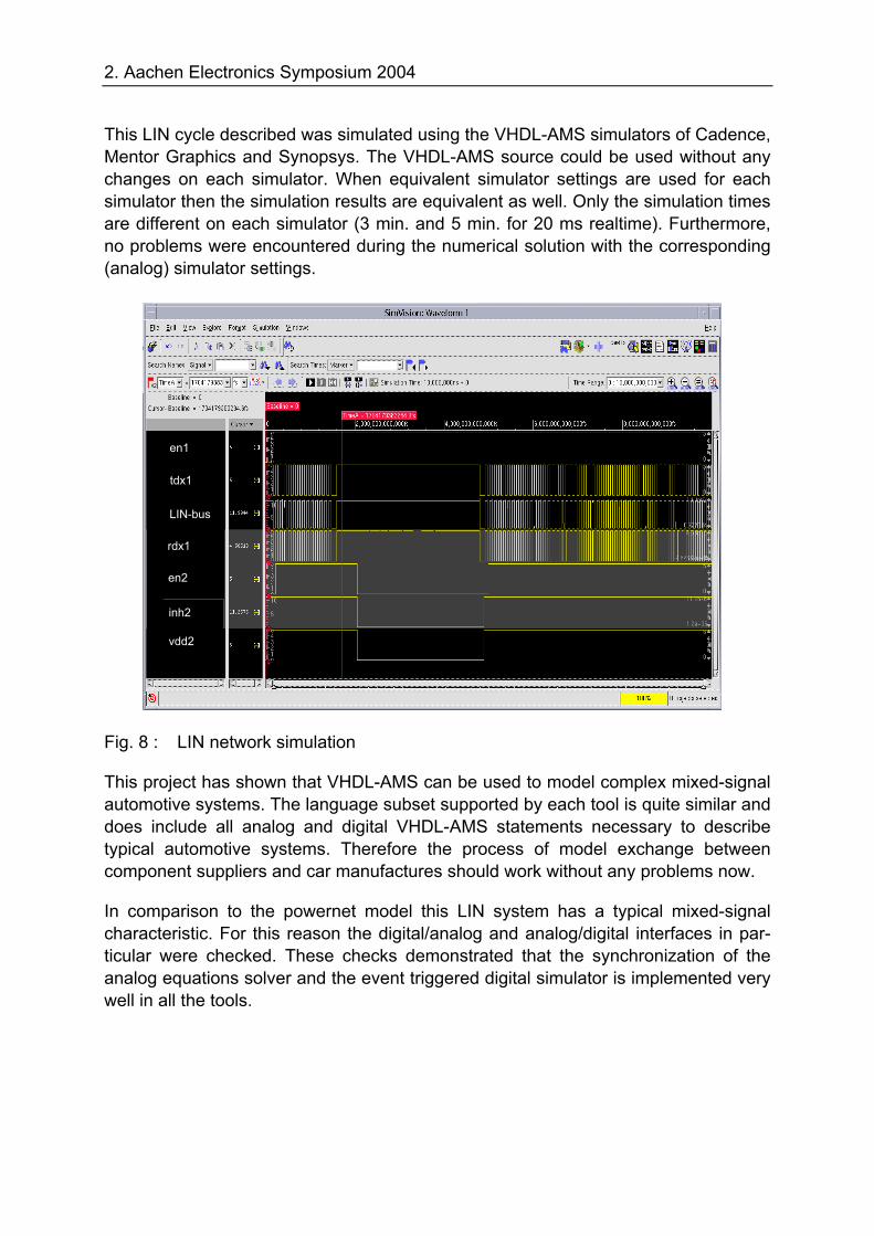
This LIN cycle described was simulated using the VHDL-AMS simulators of Cadence, Mentor Graphics and Synopsys. The VHDL-AMS source could be used without any changes on each simulator. When equivalent simulator settings are used for each simulator then the simulation results are equivalent as well. Only the simulation times are different on each simulator (3 min. and 5 min. for 20 ms realtime). Furthermore, no problems were encountered during the numerical solution with the corresponding (analog) simulator settings.
Fig. 8 : LIN network simulation
This project has shown that VHDL-AMS can be used to model complex mixed-signal automotive systems. The language subset supported by each tool is quite similar and does include all analog and digital VHDL-AMS statements necessary to describe typical automotive systems. Therefore the process of model exchange between component suppliers and car manufactures should work without any problems now.
In comparison to the powernet model this LIN system has a typical mixed-signal characteristic. For this reason the digital/analog and analog/digital interfaces in par-ticular were checked. These checks demonstrated that the synchronization of the analog equations solver and the event triggered digital simulator is implemented very well in all the tools.
en1
tdx1
LIN-bus
rdx1
en2
inh2
vdd2
12 2. Aachen Electronics Symposium 2004
4.3 EPS System
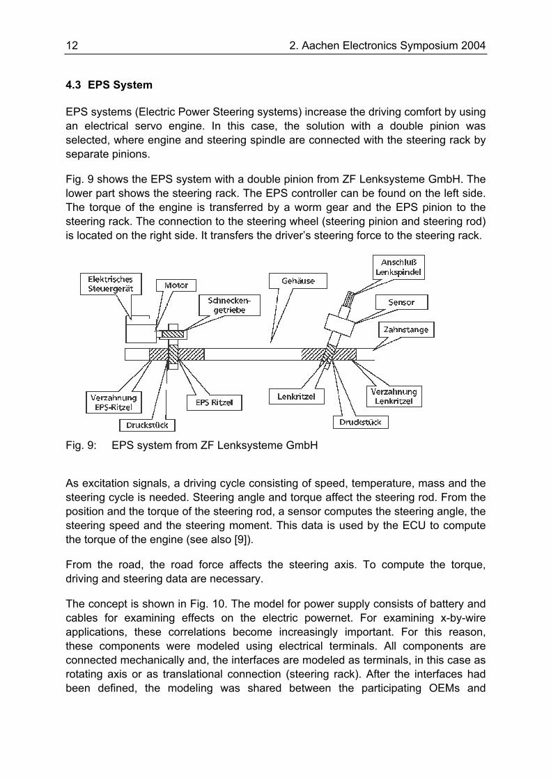
EPS systems (Electric Power Steering systems) increase the driving comfort by using an electrical servo engine. In this case, the solution with a double pinion was selected, where engine and steering spindle are connected with the steering rack by separate pinions.
Fig. 9 shows the EPS system with a double pinion from ZF Lenksysteme GmbH. The lower part shows the steering rack. The EPS controller can be found on the left side. The torque of the engine is transferred by a worm gear and the EPS pinion to the steering rack. The connection to the steering wheel (steering pinion and steering rod) is located on the right side. It transfers the driver’s steering force to the steering rack.
Fig. 9: EPS system from ZF Lenksysteme GmbH
As excitation signals, a driving cycle consisting of speed, temperature, mass and the steering cycle is needed. Steering angle and torque affect the steering rod. From the position and the torque of the steering rod, a sensor computes the steering angle, the steering speed and the steering moment. This data is used by the ECU to compute the torque of the engine (see also [9]).
From the road, the road force affects the steering axis. To compute the torque, driving and steering data are necessary.
The concept is shown in Fig. 10. The model for power supply consists of battery and cables for examining effects on the electric powernet. For examining x-by-wire applications, these correlations become increasingly important. For this reason, these components were modeled using electrical terminals. All components are connected mechanically and, the interfaces are modeled as terminals, in this case as rotating axis or as translational connection (steering rack). After the interfaces had been defined, the modeling was shared between the participating OEMs and
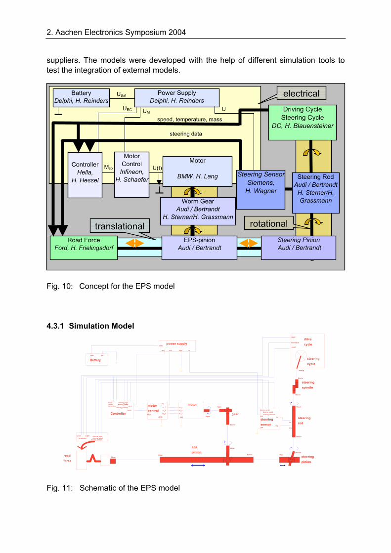
2. Aachen Electronics Symposium 2004
suppliers. The models were developed with the help of different simulation tools to test the integration of external models.
Fig. 10: Concept for the EPS model
4.3.1 Simulation Model
Fig. 11: Schematic of the EPS model
translational rotational
Controller
Hella, H. Hessel
Motor
BMW, H. Lang
Steering Pinion Audi / Bertrandt
Road Force Ford, H. Frielingsdorf
Worm Gear Audi / Bertrandt
H. Sterner/H. Grassmann
steering data
speed, temperature, mass
Motor Control
Infineon, H. Schaefer
U(t) Msol
EPS-pinion Audi / Bertrandt
Power Supply Delphi, H. Reinders
Battery Delphi, H. Reinders
UEC
UBat
UUM
Steering Rod Audi / Bertrandt
H. Sterner/H. Grassmann
Steering Sensor Siemens,
H. Wagner
Driving Cycle Steering Cycle
DC, H. Blauensteiner
motor
MgearGND
n1_2
n1_1
n1_3 gear
Mgear
Mpinion
steeringrod
Mpinion
Mcycle
tor
ang
steeringspindle
Mpinion
Mcycle
Batteryubatt gnd
Controller
speed
Msoll
temperatureweight
steering_anglesteering_speed
steering_momentuecu motor
controlMsoll
uGND
n1_2
Uma
n1_1
n1_3
power supplyubatt
uecu uma usugnd
steeringsensor
tor
steering_anglesteering_speedsteering_moment
vbat
anggnd
drivecycle
steering cycle
speed
temperature
weight
steering
epspinion
Mroad
Mgear
Mpinion
steering pinion
MepsMsensor
roadforce
speed
Mroad
temperatureweight steering_angle
steering_speedsteering_moment
electrical
14 2. Aachen Electronics Symposium 2004
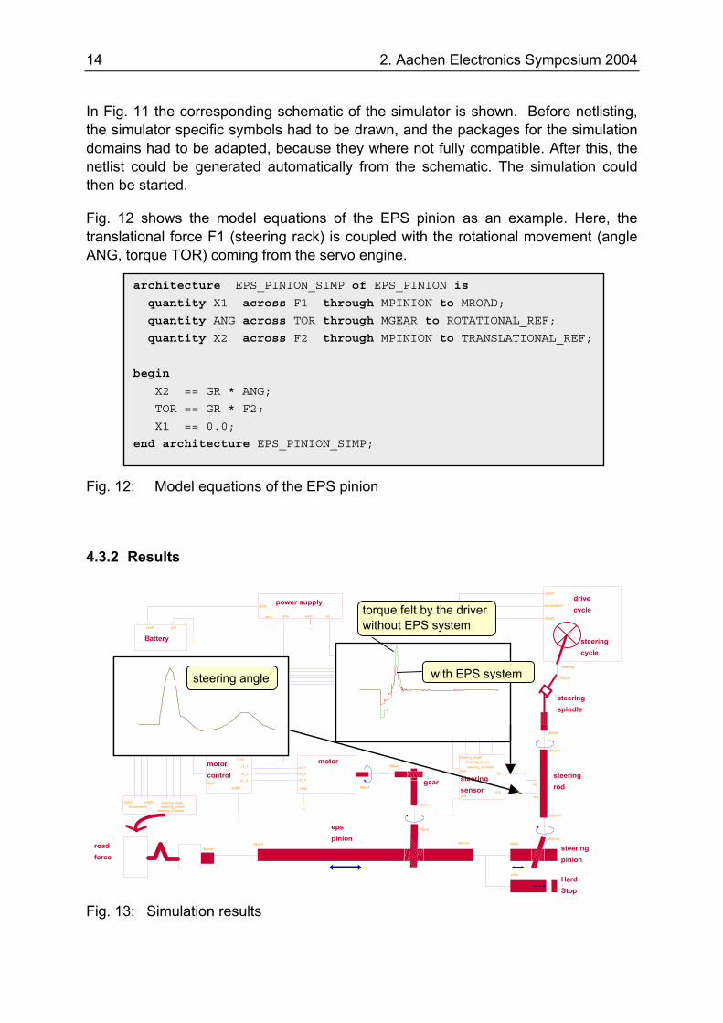
In Fig. 11 the corresponding schematic of the simulator is shown. Before netlisting, the simulator specific symbols had to be drawn, and the packages for the simulation domains had to be adapted, because they where not fully compatible. After this, the netlist could be generated automatically from the schematic. The simulation could then be started.
Fig. 12 shows the model equations of the EPS pinion as an example. Here, the translational force F1 (steering rack) is coupled with the rotational movement (angle ANG, torque TOR) coming from the servo engine.
Fig. 12: Model equations of the EPS pinion
4.3.2 Results
gear
Mgear
Mpinion
steeringrod
Mpinion
Mcycle
tor
ang
steeringspindle
Mpinion
Mcycle
Batteryubatt gnd
motorcontrolMsoll
uGND
n1_2
Uma
n1_1
n1_3
power supplyubatt
uecu uma usugnd
steeringsensor
tor
steering_anglesteering_speedsteering_moment
vbat
anggnd
roadforce
speed
Mroad
temperatureweight steering_angle
steering_speedsteering_moment
drivecycle
steering cycle
temperature
steering
speed
weight
epspinion
Mroad
Mgear
Mpinion
steering pinion
MepsMsensor
motor
MgearGND
n1_2
n1_1
n1_3
Controller
speed
Msoll
temperatureweight
steering_anglesteering_speed
steering_momentuecu
HardStop
xstop
(rea
l)
-2.0
-1.0
0.0
1.0
2.0
3.0
10.0 15.0 20.0 25.0 30.0 35.0 40.0 45.0 50.0
(rea
l)
-2.5
0.0
2.5
5.0
7.5
10.0
10.0 15.0 20.0 25.0 30.0 35.0 40.0 45.0 50.0
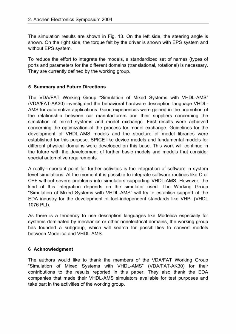
Fig. 13: Simulation results
architecture EPS_PINION_SIMP of EPS_PINION is
quantity X1 across F1 through MPINION to MROAD;
quantity ANG across TOR through MGEAR to ROTATIONAL_REF;
quantity X2 across F2 through MPINION to TRANSLATIONAL_REF;
begin
X2 == GR * ANG;
TOR == GR * F2;
X1 == 0.0;
end architecture EPS_PINION_SIMP;
torque felt by the driver without EPS system
with EPS system steering angle
2. Aachen Electronics Symposium 2004
The simulation results are shown in Fig. 13. On the left side, the steering angle is shown. On the right side, the torque felt by the driver is shown with EPS system and without EPS system.
To reduce the effort to integrate the models, a standardized set of names (types of ports and parameters for the different domains (translational, rotational) is necessary. They are currently defined by the working group.
5 Summary and Future Directions
The VDA/FAT Working Group “Simulation of Mixed Systems with VHDL-AMS” (VDA/FAT-AK30) investigated the behavioral hardware description language VHDL-AMS for automotive applications. Good experiences were gained in the promotion of the relationship between car manufacturers and their suppliers concerning the simulation of mixed systems and model exchange. First results were achieved concerning the optimization of the process for model exchange. Guidelines for the development of VHDL-AMS models and the structure of model libraries were established for this purpose. SPICE-like device models and fundamental models for different physical domains were developed on this base. This work will continue in the future with the development of further basic models and models that consider special automotive requirements.
A really important point for further activities is the integration of software in system level simulations. At the moment it is possible to integrate software routines like C or C++ without severe problems into simulators supporting VHDL-AMS. However, the kind of this integration depends on the simulator used. The Working Group “Simulation of Mixed Systems with VHDL-AMS” will try to establish support of the EDA industry for the development of tool-independent standards like VHPI (VHDL 1076 PLI).
As there is a tendency to use description languages like Modelica especially for systems dominated by mechanics or other nonelectrical domains, the working group has founded a subgroup, which will search for possibilities to convert models between Modelica and VHDL-AMS.
6 Acknowledgment
The authors would like to thank the members of the VDA/FAT Working Group “Simulation of Mixed Systems with VHDL-AMS” (VDA/FAT-AK30) for their contributions to the results reported in this paper. They also thank the EDA companies that made their VHDL-AMS simulators available for test purposes and take part in the activities of the working group.
16 2. Aachen Electronics Symposium 2004
7 References
[1] Model Specification Process Standard J2546. Society of Automotive Engineers (SAE) Inc., Warrendale, 2002.
[2] IEEE Standard VHDL Analog and Mixed-Signal Extensions (Std 1076.1-1999). The Institute of Electrical and Electronics Engineers, Inc., New York, 1999.
[3] Fedder, G. K.: Issues in MEMS Macromodeling. Proc. of the 2003 IEEE Inter-national Workshop on Behavioural Modeling and Simulation (BMAS 2003), San Jose, October 7-8, 2003, pp. 64-69.
[4] Extensible Markup Language (XML): Available: http://www.w3.org/XML/
[5] Subversion project. Available: http://subversion.tigris.org/
[6] Kreipp, A.-M.; Zuber, M.; Duba, P.; Sterner, Q.: 42V Systems and Development by Simulation. in Graf, A. (Ed.): The New Automotive 42V PowerNet. Expert-Verlag, 2002, pp. 1-28.
[7] Metzner, D.; Schaefer, J.; Xu, C.: Mixed Signal, Multi Domain Behavior Models of Smart Power ICs for Design Integration in Automotive Applications. Proc. of the 2001 IEEE International Workshop on Behavioral Modeling and Simulation (BMAS 2001), Santa Rosa, California, October 10-12, 2001.
[8] Metzner, D.; Schaefer, J.; Pelz, G.: HDL Based System Engineering for Automotive Power Applications. Proc. of the 2003 IEEE International Workshop on Behavioral Modeling and Simulation (BMAS 2003), San Jose, California, October 7-8, 2003, pp. 122-127.
[9] Graßmann, A.; Sterner, Q.: Die EPS-Lenkung als Referenz-Modell für VHDL-AMS. ASIM 2003 – 17. Symposium Simulationstechnik, Magdeburg, 16.-19. September 2003, S. 339-342.
Contact AK30:
Dipl.-Ing. Ewald Hessel Hella KGaA Hueck & Co. Beckumer Str. 130 D-59522 Lippstadt Germany
E-Mail: [email protected]