modelling and control of wind farms integrated with
TRANSCRIPT

HAL Id: hal-01573257https://hal.archives-ouvertes.fr/hal-01573257
Submitted on 9 Aug 2017
HAL is a multi-disciplinary open accessarchive for the deposit and dissemination of sci-entific research documents, whether they are pub-lished or not. The documents may come fromteaching and research institutions in France orabroad, or from public or private research centers.
L’archive ouverte pluridisciplinaire HAL, estdestinée au dépôt et à la diffusion de documentsscientifiques de niveau recherche, publiés ou non,émanant des établissements d’enseignement et derecherche français ou étrangers, des laboratoirespublics ou privés.
Modelling and Control of Wind Farms Integrated withBattery Energy Storage Systems
Mohammad Taghi Zareifard
To cite this version:Mohammad Taghi Zareifard. Modelling and Control of Wind Farms Integrated with Battery EnergyStorage Systems. [Research Report] university of new south wales 2017. �hal-01573257�

Modelling and Control of Wind FarmsIntegrated with Battery Energy Storage
Systems
by
Mohammad Taghi Zarei Fard
2017

Abstract
The ever expanding of greenhouse gas emission and limitation of fossil energy sourcesare driving demand for the green energies. Among the variety of the renewable en-ergy sources, the wind power in large scale is known as the best replacement for theconventional source of energies. However, due to the intermittency of wind power,this source without any control is not efficient neither technically nor economically.Technically, fluctuation of wind power should be smoothed while it is dispatched tothe grid power to avoid system faults. On the other hand, in competitive deregu-lated electricity market, the financial issue concerns the economic revenue of windpower plant. It is well understood that applying storage system with proper controlmechanism is required to address to technical and economical shortcomings.
In this report, a new control strategy is presented to manage the amount ofenergy that is generated by wind farm plant and sold to the electricity market.Contributions of this report are three-fold: 1. As the battery plays a fundamentalrole in our control system, we addressed a novel generic battery model which reflectsthe effects of chemical reactions as the battery is charging, discharging and storingenergy; 2. Our control method reduces the fluctuation of supplied wind power whileit empowers the operator to make a balance between energy supply and demandin a profitable way using battery energy storage; 3. Lastly, we employ monotoniccharging and discharging strategy in our control system to maximize the profit ofWPP operator by significantly reducing the capital cost.
Optimization of the overall system behavior given physical constraints using theModel Predictive Control (MPC) is one of the advantages of the proposed system.Moreover, adaptive updating of a reference signal based on system states, predictedprice and wind power data helps improve the controllability of the wind farm powergeneration with the Battery Energy Storage System BESS into the electricity mar-ket while keeping the ramp rate of the power signal within a predefined range.Furthermore, it is depicted that battery capacity has highly affected on profit ofthe WPP. Therefore, choosing a suitable amount of battery for a specific WPP canimprove the efficiency accordingly. The controller managing the Wind and batteryenergy storage is based on MPC theory and dynamic programming. Wind and pricepredictions are attached to the system for enhancing its improvement.
ii

Contents
1 Introduction 2
1.1 Introduction . . . . . . . . . . . . . . . . . . . . . . . . . . . . . . . . 2
1.2 Wind power challenges . . . . . . . . . . . . . . . . . . . . . . . . . . 3
1.2.1 Technical wind power challengers . . . . . . . . . . . . . . . . 3
1.2.2 Economical wind power challengers . . . . . . . . . . . . . . . 3
1.3 Energy storage and wind power . . . . . . . . . . . . . . . . . . . . . 4
1.4 Australian energy market . . . . . . . . . . . . . . . . . . . . . . . . . 4
1.5 Control system design . . . . . . . . . . . . . . . . . . . . . . . . . . 5
1.6 Contributions . . . . . . . . . . . . . . . . . . . . . . . . . . . . . . . 5
1.7 Report outline . . . . . . . . . . . . . . . . . . . . . . . . . . . . . . . 6
2 A Nonlinear Battery Model 7
2.1 Introduction . . . . . . . . . . . . . . . . . . . . . . . . . . . . . . . . 7
2.2 Battery Model . . . . . . . . . . . . . . . . . . . . . . . . . . . . . . . 8
2.2.1 Charging and discharging analysis of the battery . . . . . . . . 9
2.3 Modeling battery energy storage for wind power plant application . . 10
2.4 BESS model for Sodium Sulfur (NAS) battery . . . . . . . . . . . . . 12
2.5 Conclusion . . . . . . . . . . . . . . . . . . . . . . . . . . . . . . . . . 15
3 Model Predictive Control for Wind Power Generation Smoothingwith Controlled Battery Storage Based on A Nonlinear BatteryMathematical Model 16
3.1 Introduction . . . . . . . . . . . . . . . . . . . . . . . . . . . . . . . . 16
3.2 Problem Statement . . . . . . . . . . . . . . . . . . . . . . . . . . . . 17
3.3 Control System Design Description . . . . . . . . . . . . . . . . . . . 18
3.3.1 Proposed Prediction Model . . . . . . . . . . . . . . . . . . . 19
3.3.2 Controller Design . . . . . . . . . . . . . . . . . . . . . . . . . 19
3.4 Simulation . . . . . . . . . . . . . . . . . . . . . . . . . . . . . . . . . 21
3.4.1 Database . . . . . . . . . . . . . . . . . . . . . . . . . . . . . 21
3.4.2 Battery Type Selection . . . . . . . . . . . . . . . . . . . . . . 21
3.4.3 Results and discussion . . . . . . . . . . . . . . . . . . . . . . 22
3.5 Conclusion . . . . . . . . . . . . . . . . . . . . . . . . . . . . . . . . . 23
iii

4 Maximizing Profit of a Wind Battery Energy System Using ModelPredictive Control Driven by a Dynamic Reference Policy 264.1 Introduction . . . . . . . . . . . . . . . . . . . . . . . . . . . . . . . . 274.2 Problem Description . . . . . . . . . . . . . . . . . . . . . . . . . . . 29
4.2.1 Dynamic model of the system . . . . . . . . . . . . . . . . . . 294.2.2 Reference Generator . . . . . . . . . . . . . . . . . . . . . . . 294.2.3 Wind Power Prediction Model . . . . . . . . . . . . . . . . . . 314.2.4 Price Prediction . . . . . . . . . . . . . . . . . . . . . . . . . . 314.2.5 Controller Design . . . . . . . . . . . . . . . . . . . . . . . . . 31
4.3 Simulations . . . . . . . . . . . . . . . . . . . . . . . . . . . . . . . . 334.3.1 Dataset . . . . . . . . . . . . . . . . . . . . . . . . . . . . . . 334.3.2 Battery Type Selection . . . . . . . . . . . . . . . . . . . . . . 344.3.3 Results . . . . . . . . . . . . . . . . . . . . . . . . . . . . . . . 344.3.4 Impact of dynamic storage policy . . . . . . . . . . . . . . . . 38
4.4 Summary . . . . . . . . . . . . . . . . . . . . . . . . . . . . . . . . . 45
5 A Simulation Study on Impact of Monotonic Battery Charg-ing/Discharging on Cost and Revenue of Wind Power Plant 475.1 Introduction . . . . . . . . . . . . . . . . . . . . . . . . . . . . . . . . 475.2 Problem Statement . . . . . . . . . . . . . . . . . . . . . . . . . . . . 485.3 Monotonic charging/discharging methodology . . . . . . . . . . . . . 495.4 Control System Design Description . . . . . . . . . . . . . . . . . . . 49
5.4.1 Dynamic Model of the System . . . . . . . . . . . . . . . . . . 495.4.2 Controller Design . . . . . . . . . . . . . . . . . . . . . . . . . 50
5.5 Simulation Results . . . . . . . . . . . . . . . . . . . . . . . . . . . . 535.6 Conclusion . . . . . . . . . . . . . . . . . . . . . . . . . . . . . . . . . 56
6 Conclusions and Future Works 586.1 Conclusions . . . . . . . . . . . . . . . . . . . . . . . . . . . . . . . . 586.2 Future works . . . . . . . . . . . . . . . . . . . . . . . . . . . . . . . 59
1

Chapter 1
Introduction
1.1 Introduction
In recent years, energy policies of worldwide are moving toward exploiting RenewableEnergy Sources (RES) such as the wind and solar energies. Since greenhouse gasemission is caused by consumption of fossil energies, it persuades governments tomotivate electricity plant operators to switch to the renewable sources. Moreover,increasing electricity demand and the crisis in fuel price in the world led us to utilizegreen resources. Due to the technology improvements among all renewable energyresources, wind power gets the attention of many developed countries as a clean andcheap source of energy for future generation. [1, 2].
Furthermore, Recent impressive technical and economical developments in windpower energy generation led to engage large percentage of electricity generation bythis source of energy specially in European countries such as Denmark and Germany[3,4]. However, there are many troubles and challenges ahead when large percentageof energy produce by wind power as its pure power without any control can notsatisfy the standards.
There are some technical and financial issues ahead of applying this source ofenergy which are required to be organized in a way that wind power can be dis-patchable to the grid network to be technically reliable and financially profitable.
In this regard, some issues such as fluctuation of wind power plant output thatcauses by the nature of wind power should be controlled so that the output powerto the grid can not destroy the electricity grid [5, 6]. Other trouble that shouldbe managed is the stability of wind power. Furthermore, since Wind Power Plants(WPPs) in large scale are one of the major electricity producers in developed coun-tries [7], they need to contend in the competitive electricity market to sell theirenergy. Therefore, again fluctuated nature of this source of energy raises anotherchallenge which needs to be deliberated to improve the overall income of the WPP.
2

1.2 Wind power challenges
1.2.1 Technical wind power challengers
In order to increase the portion of wind power in network electricity grid in comparewith other sources of energies, we need to decrease the issues that raise up in usageof wind power. The intermittency of wind power is called ’Ramp Rate’ [8]. Thisphenomenon should be under control that this power be able to match the standardsof electricity network grid. In Fig.1.1 a sample of one day wind power is illustrated.Ramp rate is shown in this typical real sample of wind power for one day. Anotherchallenge is transmission of wind power in large scale. In this situation, in order toavoid congestion in the line that transmit the power, the output power needs to becrossed off [9].
4am 8am 12pm 4pm 8pm 12am 4amTime
0
50
100
150
Pow
er (
MW
)
Figure 1.1: One day typical wind power.
1.2.2 Economical wind power challengers
In the competitive deregulated electricity market such as in Australia, financial issueconcerns the economic revenue of wind power plant. Although wind power is acces-sible occasionally depends on weather condition, an appropriate control strategy isrequired to maximize the economic benefits form WPP.
3

1.3 Energy storage and wind power
At first glance, a applicable solution to cope with this challenge is adding an EnergyStorage System (ESS) to the wind power plant. This idea not only can save theenergy in times of off peak and low demand but also it can reduce all technicalchallenges which explained above [10]. Currently, the cost of this technology isquiet high [11] but there are such a good improvements have be done in this areato reduce the capital cost of energy storages.
In recent years there are two main subjects that researchers have focused on asinterested fields in renewable energy industry.
1- Reducing the ramp rate or in other word smoothing the output power fromwind power plant
2- Increasing profit of implementing wind power in the competitive electricitymarket.
A key objective of both problem statements leads to make the wind power moredispatchable. Since In majority of related works, energy storage system is integratedto the wind, we first review battery energy storage as the main tool in this studyand then its application in wind power plant will be discussed. There are severalenergy storage technologies which are applied in industries to store the energy recentyears. Flywheels, batteries, supercapacitors, hydrogen, pneumatic, and pumpedstorage technologies are some examples which they are currently employed in powerindustry to accumulate the energy for different purposes. Review studies on energystorage technologies show that batteries are the common devices that apply for powersystem utilities [12]. Therefore, in this report we focus on battery energy storage asa powerful and reliable devise for storage and control purposes. Using batteries incombine with wind power plant will improve not only the overall performance of thedispatched power but also it will increase the total revenue of WPP. However, thereare different strategies in applying BEES with WPP [12] .Hence, one of main scopesof this report is using an appropriate control strategy to raise the performance ofbattery and at the same time mitigate the explained challenges while using windpower. To increase the performance and also improve accuracy of the controller,we are looking for an appropriate battery model which reflects the characteristicsof battery features. In all previous studies, battery models belong to a specifickind of battery and therefore it cannot be applicable to other type of batteries.In this report we propose a new nonlinear battery model which represents mostproperties of a battery while it is integrate with wind power plant. With the aid ofthis comprehensive nonlinear model, we can control the system by considering mostfeatures of the system and in this regard designing the controller could be moreaccurate in compare with related works.
1.4 Australian energy market
Studying on Electricity market by itself is a research topic which is out of the scopeof this report. However, we need to apply the regulations of electricity market
4

in our design section to improve the revenue of WPP. Therefore, a perspective ofAustralian National Energy Market (ANEM) as the case study target is required.ANEM is known as one of the powerful and dynamic markets in the world. Weproposed our control strategies in price section based on the regulation of ANEMsince our data basis in this report gathered from ANEM. The regulations will beexplained in chapter 4 of this report.
1.5 Control system design
In the last few decades, Model Predictive Control (MPC) has gained the attentionof researchers in industry to obtain the benefit of this control method to enhance theperformance and capabilities of their systems. One of the most important factorswhich effect on choosing this control method in industry and is its potential to handlethe systems with physical limitations which are difficult to control with other controlmethods such as PID. Wind power plant as the case study of this report, has varietyof practical system constraints such as battery charging and discharging thresholdand wind power plant maximum and minimum capacity. Indeed, we choose MPCas a practical solution to mitigate these challenges. Since the nonlinearity of thebattery model, dynamic programming as a powerful optimization tool has beenselected in this study which will be expanded in chapters 4-6.
1.6 Contributions
Nowadays, wind power penetration in worldwide is increasing with a high rate incompare with other types of renewable energy sources; therefore, we highlighted thechallenges that turn up as a result of connecting wind power into the electricitymarket, technically and financially. Batteries provide a feasible solution when theyare integrated with wind farms. As one of the main contributions of this report, weproposed a new nonlinear battery model which has a general characteristic ratherthan type of battery in order to facilitate designing a hybrid battery and wind power.This model considers internal features of battery by defining specific parametersbased on battery type. In the next stage, we implemented the new model to smoothout the wind power output using model predictive control. Since the proposed modelis nonlinear, the optimization method which we combined with MPC is dynamicprogramming. As the other novel contribution in this study, we proposed a referencegenerator in our controller design section to improve the performance of the outputplant. The policy of this reference generator is based on wind power and electricitymarket price prediction. The policy behind applying this mathematical referencegenerator in the proposed control scenario is increasing overall revenue of the plant.At last, this study provides a solution to choose an appropriate battery capacityfor any specific wind power plant while it is connected to battery energy storage byconsidering maximum revenue of the plant. Since the charging/discharging behaviorof battery has a significant impact on both cost and revenue of wind power plant
5

(WPP), we combine the monotonic charging/discharging methodology to our systemdesign. This causes minor reduction in revenue of wind power plant by decreasingthe total battery capacity while we employ optimal size of BESS.
1.7 Report outline
In this chapter we explained about the basic motivation for the work and introducedthe problem statement. We also highlighted the contributions of the study in brief.The rest of the report is organised as follows:
Chapter 2 presents a new and novel nonlinear battery model. In this chapterfirstly we discuss about the reasons of designing a new battery model. In addition,the detail stages of designing a general state space battery model are explained.Since the this model designed for any type of batteries depends on the definedparameters, we choose Nas battery (sodiumsulfur battery) as a case study and weproposed this specific battery model for implementation in later chapters in orderto control the wind power.
Chapter 3 provides a control strategy to decrease the ramp rate of the windpower with the aid of new model which defined in chapter 3. We present an MPCapproach to smooth wind power fluctuations while the plant integrated with BESS.Next the control objectives and physical constraints of the system are specified.Following that, an overview and a basic formulation of model predictive controllerwith dynamic programming optimization is described. Then, the efficiency of thiscontrol strategy is assessed under different scenarios via simulation of an actual windfarm data.
Chapter 4 covers a market oriented control approach of wind power plant. Inthis chapter, we model a wind power plant in a close loop system. We implementMPC with dynamic programming approach to increase the overall revenue of WPP.In this chapter we propose a strategy to produce a reference signal which is basedon a mathematical model. Then, the simulation results are presented. The windpower data which applied in the simulation are obtained form an actual wind powerplant in Australia and also the price data are provided by Australian energy marketdatabase. At the end, the battery capacity and its effect on revenue is examinedunder different scenarios in order to provide a best match capacity with specificwind power plant.
Chapter 6 brings forward the effect of charging/discharging methodology andoptimal battery capacity on both the cost and the revenue of wind power plant.In this chapter we apply the monotonic charging/discharging strategy as one ofthe effective solutions of reducing both overall battery capacity and capital costof wind power plant on the control system design which has been introduced inchapter 5. Following that, the revenue analysis of WPP in presence of monotoniccharging/discharging strategy is discussed.
chapter 7 concludes the report by discussing the achievements of this report andpotential future works.
6

Chapter 2
A Nonlinear Battery Model
Due to the recent researches in the renewable energy area, integrating wind powerplants to a energy storage systems is a method to enhance the technical efficiencyof WPP and also increase the revenue of these systems [13]. Furthermore, somestudies are dedicated to the type of ESS in order to determine what kind of ESStechnologies are technically more adjustable to WPP. In [12, 14], all types of ESSstechnologies are compared and finally the authors in [12] suggested that batteryenergy energy storage system is a suitable choice for integrating with wind farms inorder to reach to a maximum benefit. However, an important issue in this regardis the model of the battery. In the last few years, lots of efforts have been accom-plished to generate a model for the batteries. In [15–18] a few models are designedbased on the type of batteries and their unique specifications. Most of them useimpractical assumptions that lead to some errors when they employ in integrationwith WPP. [19,20]. Therefore, a novel nonlinear battery model which reflects mostcharacteristics of battery is presented in this chapter.
2.1 Introduction
In recent years, battery becomes one of the most attractive researched elementsbecause of its significant rule in power systems engineering and specifically in re-newable energy plants such as wind power [21–23]. Integrating batteries with windpower plant provides an opportunity to develop the technical and financial issuesrelated to wind power nature [19, 20]. In most of the studies, researchers empha-sis on battery technology, battery chemistry, battery charging-discharging scheduleand some studies concentrate on battery parameter estimation. However, there isnot any comprehensive model which reflect all features of batteries and can be ex-pandable to all types of batteries in order to simulate battery model in wind powersystem.
In order to estimate parameters of the battery, large quantity of data is needed toproduce a model based on experimental data and therefore in this type of estimationwhich is not accurate the model is unique and it can not be expanded to other typesof batteries even in the same category [24–27]. Due to lack of a generic model for
7

batteries in simulation studies, there are variety of softwares which can be applied.In this case, there are some problems that occurs. For instance, they only reflectbattery charging or discharging characteristic. In the other words, available modelsare not capable to reflect the behaviour of battery in all the possible situations suchas charging, discharging and storing periods.
In [28] a type of generic battery model has been introduced. In this study, themanufacturers battery discharging characteristic curves is represented with the aidof data sheet of that specific battery model. However, this method as we describedearlier in this chapter are not be able to show a comprehensive schematic of batter-ies. For instance in [28] hysteretic effect is assumed to be zero and therefor in thecases that current of discharging is high this proposed model will not be accurateenough. In order to avoid generating excessive complexity, in [19,20] representativemodels for the battery is considered as linear for simplicity. They consider the linearrelationship between input and output of the energy.
These type of linear models [20] imply that the total energy is entered into thebattery can be delivered out with no loss and therefore the battery model rolesas an ideal storage with 100 % efficiency. This model is not able to representsome parameters which impact on the battery as some chemical reactions inside thebattery [29] that cause nonlinear behavior during charging, storage and discharging.There are also some ambient effects such as temperature and humidity that caninfluence the performance of the battery.
Each type of battery based on its chemical and physical character has a differentmathematical model. Though, a unique model which can be applicable to all typesof batteries has not been published yet.
Therefore in this chapter, we introduce a generic model which can be spreadout to any type of battery by defining its coefficient depends on the specific typeof battery. To achieve a good estimation of the output of wind power plant, weneed a battery model that considers the leakage of the energy and the rate of charg-ing/discharging. One of the advantages of this model is that it takes into accountthe leakage of the energy inside the battery not only during charging and dischargingbut also when the energy is stored inside it.
2.2 Battery Model
In general there are different types of battery model which are applicable in industryand research studies. Some models are based on voltage and current of batterycircuits which explained in chapter 2. These types of models are not matchedwith energy models when the battery is simulated in energy model of wind powerplant. Therefore, in our later control design we are looking for a energy modelof battery which describes features of this energy storage system. Before we gothrough the design part of the research we need to have an overview about thebattery characteristic.
8

2.2.1 Charging and discharging analysis of the battery
Basically, any changes inside of the battery include charging, discharging and storageprocesses are based on chemical reactions which varies with the following conditions:
1. State of Charge
2. Battery storage capacity
3. Rate of charge/discharge
4. Environmental temperature
Hence, in order to have a comprehensive model, each of these conditions shouldbe considered.
Since we are going to introduce a generic energy model of the battery, we dividethe battery behaviour within three main periods:
• Charging period
• Discharging period
• Storing period
In each of the above durations, battery has different action which is essential tobe analysed before designing the model.
Charging mood
While the battery is charging, a conversion of energy occurs inside the battery. Basedon the parameters such as ambient temperature, rate of charge, battery capacity andstate of charge, a specific amount of entering energy absorbed inside the battery.For instance, there are some losses within the internal resistance of battery whichresults a fraction of energy to be dumped.
Discharging mood
During the discharge process, similar to the charging regime, ambient temperature,rate of charge, battery capacity and state of charge of the battery influence on theamount of energy which is extracted from the batter. However, these effects are notthe same as charging based on empirical results from any type of batteries. It isobserved that the percentage of loss energy in the discharging process is larger thanthe time of charging with the same conditions.
To have a exact overview about the characteristic of battery during chargingand discharging process, manufacturer data is mandatory which is provided in theircatalogue. Therefor, we employ these data in our design and it is explained in nextsection.
The effect of temperature also need be investigated since it can change therhythm of charging and discharging. In [30] and [31] this phenomena is studiedfor various temperature for Li-ion batteries and lead acid batteries respectively.
9

Figure 2.1: Effect of temperature on battery capacity [32].
Storage mood
In those times that energy stores inside the battery without any charging or dis-charging, some energy will loss due to the chemical reactions inside the battery. Therate of this deduction is factors which is highly depends on type of battery and thematerials which the battery has been made by them [32].
In all of the above mentioned situations, temperature plays a fundamental rulesince its has highly effect on the performance of the battery. Fig.2.1 shows the impactof temperature on lead acid battery capacity. In order to achieve maximum efficiencyfrom the battery, normal ambient temperature which is 25◦ as the experimental testresults reveal this idea [32].
The age of battery is another factor which has direct influence on its output.Experiments reveal that self discharge rate of the batteries increase as the its agegrow up [32].
2.3 Modeling battery energy storage for wind power
plant application
On of the important issues in modeling renewable energy plant is providing a simpleand applicable model although it is comprehensive. Battery energy storage is akey part of wind power plant, though a practical model help a control designer tocontrol and optimize the performance of real plant easier. As mentioned earlierin introduction and literature review sections, there are variety of battery energystorage models which each of them specifically represent one particular type ofbattery. In this these we put our effort to propose a new generic model based on allproperties of batteries which has been explained earlier in this chapter. This new
10
model can be applied to any type of batteries by defining some parameters whichare required to be identified.
Since the real behaviour of the battery is nonlinear and we are looking for amodel which demonstrate this manner, a nonlinear model of BESS is defined in thestate space form as follows:
x(k + 1) = f(x(k)) + g(x(k), u(k)) (2.1)
We define functions f and g as follow,
f(x) = α(x)x (2.2)
and,
g(x, u) =
β(x)Mc for u > Mc
β(x)u for 0 ≤ u ≤Mc
−γ(x)u for −Md ≤ u < 0
−γ(x)Md for u < Md
(2.3)
with following constraints
f(x(k)) ≤ x(k) ∀ x(k)
g(x(k), 0) = 0 ∀ x(k)
g(x(k), u(k)) ≤ u(k) ∀ x(k), u(k)
(2.4)
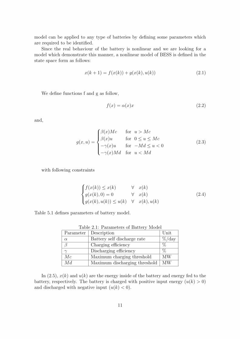
Table 5.1 defines parameters of battery model.
Table 2.1: Parameters of Battery ModelParameter Description Unitα Battery self discharge rate %/dayβ Charging efficiency %γ Discharging efficiency %Mc Maximum charging threshold MWMd Maximum discharging threshold MW
In (2.5), x(k) and u(k) are the energy inside of the battery and energy fed to thebattery, respectively. The battery is charged with positive input energy (u(k) > 0)and discharged with negative input (u(k) < 0).
11

Figure 2.2: Function g(x,e)
According to the experimental results from different type of batteries such aslead acid and sodium sulfur (NaS), and based on the trend of charging, dischargingand storage moods, functions f and g are designed by the following strategies. In(2.6), function f captures the state loss while energy is stored in the battery. Rateof loss is defined by battery self-discharge rate (0 < α(x) < 1) which varies on x.The absorbed energy in battery is represented by g in (2.7) as a function of feededenergy (u(k)) and also amount of energy inside the battery (x(k)) . In Fig. 3.8,atypical the behaviour of function g is illustrated. For positive input energy, thebattery will be charged by the rate of β(x) (0 < β ≤ 1) till it gets saturated atMc. The same trend is observed in the discharging process by rate of γ(x) (γ ≥ 1),when input energy is negative. Depends on the amount of state x, α, β and γ willbe changed. In general case, there is a contrariwise relation between x and thesecoefficients. This idea comes from the fact that if battery reaches to its full capacity,a higher percentage of energy will lose inside it. The relationship between α, β andγ and x can be figure out by experimental examination on a specific type of battery.
2.4 BESS model for Sodium Sulfur (NAS) bat-
tery
As a case study, we choose NAS (sodium-sulfur) battery because of its compatibilitywhen it is integrated to the wind power plant in compare with other type of batterytechnologies. The NAS battery was firstly implemented as a device to manage theenergy for purpose of ’load leveling’ and ’peak shaving’ and the first place which this
12

Figure 2.3: ’System size Vs discharge time of NAS battery in compare with othercommon industrial batteries’ [38].
type of battery applied was in Japan [14,33,34]. Due to the technology developmentin the industry of battery production, NAS was designed in such a way to responsein large scale in order to increase the quality of power in demand section [35–37].
There are three main reasons that we choose this type of battery in our study:
1. Long duration
2. High Power
3. Long life expectancy
1- Long durationIt is shown that NaS batteries among other kind of batteries are more suitable
for large scale usages such as implementing them in wind power plants [33]. In theother word, NaS batteries are able to produce energy three times more than leadacid batteries as a result of their ’per unit volume’ which are higher in compare withthe lead acid ones [35]. In Fig.2.3 this feature is illustrated.
2- High powerNas batteries are compatible with large scale plants such as wind or solar (10 to
100s of MW) [33, 35, 38]. In order to control wind power plant in large scales, NASis the best choice in terms of its efficiency and compatibility.
3- Long life expectancyOne of the other features of this specific battery is its high capacity in terms of
energy and its ’long life span’ as it is counted at 100% depth of discharge (DOD) upto 2500 cycles [39]. Fig.2.4 shows a typical wind power plant which is equipped withNAS battery. Based on the data collection from manufacturer catalogue of NASbattery which includes charging and discharging trends and also other factors suchas temperature effects, we extracted our model parameters for this batter. Later inchapter 4,5 and 6 we employ this model in our control designs. In order to simplifythe model, in this particular case of study, we assume all α, β and γ as constant forall x. Battery model parameters are defined in Table.2.2.
13

Figure 2.4: A sample wind farm with capacity of 34MW 51 MW and integratedNAS battery with capacity of (245 MWh). [38].
Table 2.2: Battery model parameters for NAS batteryα 0.98β 0.95γ 1.05Md -37Mc 54
14

Therefore, the nonlinear NAS battery model is as follow:
x(k + 1) = f(x(k)) + g(x(k), u(k)) (2.5)
Which based on the battery model parameters in Table.2.2, functions f and gare defined as:
f(x) = 0.98x (2.6)
and,
g(x, u) =
0.95Mc for u > Mc
0.95u for 0 ≤ u ≤Mc
−1.05u for −Md ≤ u < 0
−1.05Md for u < Md
(2.7)
2.5 Conclusion
Battery energy storage system plays a fundamental role in controlling and enhancingthe performance of renewable energy sources. There are wide range of batteries inindustry and each type has its own unique features. Control designers need to figureout appropriate mode base on the battery that they apply in their system. Therefore,lack of a generic energy model of BESS for all types of batteries is sensed. In thisstudy, based on all features of batteries and a deep literature review on availablebattery models, we proposed a generic energy model for BESS which can be exploitedin renewable energy plant applications. As a case study for later works, we providedmodel parameters for NAS battery in this chapter.
15

Chapter 3
Model Predictive Control forWind Power GenerationSmoothing with ControlledBattery Storage Based on ANonlinear Battery MathematicalModel
The aim of this chapter is to design a controller based on model predictive control(MPC) theory along with a nonlinear battery energy storage model to smooth windpower output by controlled storage of the wind energy in battery with respect touse battery plant and battery constraints. The goal of the control is to use BESSmaximally smoothing the output power dispatched to the grid while using forecastedwind power. This chapter is organised as follows. A brief introduction is providedin section 4.1. Following that, section 4.2 states the problem. In section 4.3 theproposed control system and the controller design are described. The simulationresults are given in Section 4.4 .Finally, the chapter is concluded in Section 4.5.
3.1 Introduction
In recent years, due to technology improvements among all other renewable energyresources, wind power gets attention of many developed countries as a clean andcheap source of energy for future generation [1, 2]. However, Stochastic natureis a significant challenge of this source of energy which brings intermittency dueto different weather conditions during a year. This kind of behaviour should bemanaged to prevent some unpredictable conditions that may have impact on thestability of the system. In order to have a reliable electricity grid which connectedwith a wind power plant, some measures may be required to smooth the outputfluctuation [40,41].
16
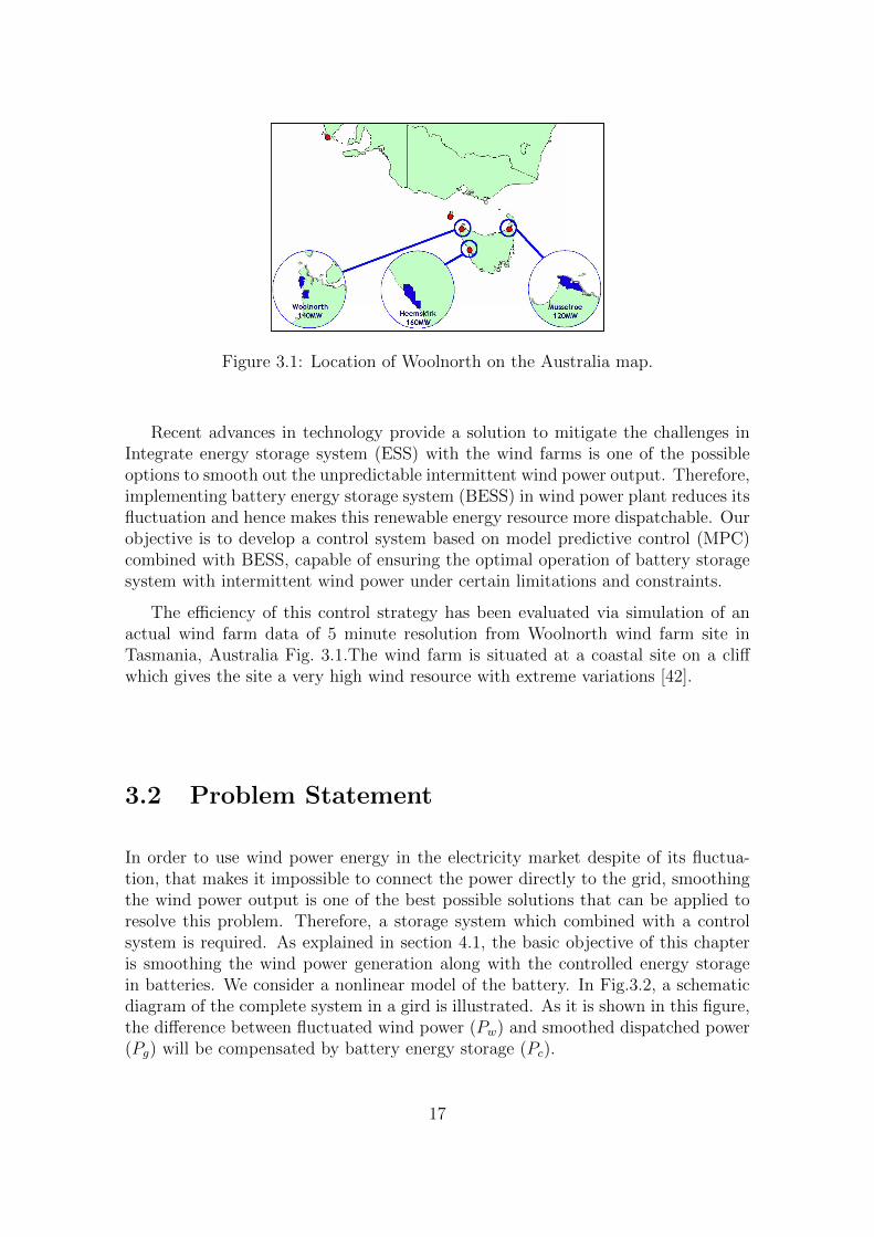
Figure 3.1: Location of Woolnorth on the Australia map.
Recent advances in technology provide a solution to mitigate the challenges inIntegrate energy storage system (ESS) with the wind farms is one of the possibleoptions to smooth out the unpredictable intermittent wind power output. Therefore,implementing battery energy storage system (BESS) in wind power plant reduces itsfluctuation and hence makes this renewable energy resource more dispatchable. Ourobjective is to develop a control system based on model predictive control (MPC)combined with BESS, capable of ensuring the optimal operation of battery storagesystem with intermittent wind power under certain limitations and constraints.
The efficiency of this control strategy has been evaluated via simulation of anactual wind farm data of 5 minute resolution from Woolnorth wind farm site inTasmania, Australia Fig. 3.1.The wind farm is situated at a coastal site on a cliffwhich gives the site a very high wind resource with extreme variations [42].
3.2 Problem Statement
In order to use wind power energy in the electricity market despite of its fluctua-tion, that makes it impossible to connect the power directly to the grid, smoothingthe wind power output is one of the best possible solutions that can be applied toresolve this problem. Therefore, a storage system which combined with a controlsystem is required. As explained in section 4.1, the basic objective of this chapteris smoothing the wind power generation along with the controlled energy storagein batteries. We consider a nonlinear model of the battery. In Fig.3.2, a schematicdiagram of the complete system in a gird is illustrated. As it is shown in this figure,the difference between fluctuated wind power (Pw) and smoothed dispatched power(Pg) will be compensated by battery energy storage (Pc).
17

Figure 3.2: Diagram of the grid-connected wind farm integrated with BESS
3.3 Control System Design Description
In this study, we propose the following control system model for wind power energystorage system, {
x1(k + 1) = r(k)− u(k)
x2(k + 1) = f(x2(k)) + td.g(x1(k), x2(k)),(3.1)
With the following cost function
J :=
N0+N∑k=N0
((r(k)− u(k))2 → min (3.2)
Subject to following constraints,
0 ≤ u(k) ≤ c3 (3.3)
−c4 ≤ u(k)− u(k − 1) ≤ c4 (3.4)
0 < c2 ≤ x2(k) ≤ c1 (3.5)
−c5 ≤ x1(k) ≤ c5 (3.6)
Physical concepts of constraints of proposed system has been explained in briefin [9], [43], [20] and related references in these studies. In 5.1, r(k) denotes as theproduction output of the farm, and let u(k) represents as the amount of energy sentto the grid, x1(k) is the error between the real and smoothed power, x2(k) is thebattery state of charge. For positive values of x1(k) (x1(k) > 0), the battery energy
18

storage will be charged and it will be discharged for negative ones (x1(k) < 0). Fur-thermore, the cost function (5.6) penalize the deviations of wind smoothed powerfrom the actual wind power. There are some constraints which imposed by thissystem that indicated by (c1), (c2), (c3), (c4), (c5). In order to keep the smoothedoutput of the system between 0 and rated value of the wind power (c1), constraint(5.8) is introduced. Constraint (5.10) is defined to control the degree of smooth-ing. It describes the difference between two consecutive amounts of smoothed windpower. The constraint (5.7) is chosen to avoid overloading or under loading of thebattery and c5 in (3.6) is the maximum charging/discharging rated capacity of thebattery. In (5.1), td is conversion coefficient (MW to MWh for each 5 min), i.e.,td = 5min/60min = 1/12. This value is chosen based on Australian energy marketoperator (AEMO) [44] which defines 5min for power dispatch process. Therefore,each k step is 5 min (t = kh, k = 0, 1, 2, ..., and h = 5 is the sampling time inminutes).
3.3.1 Proposed Prediction Model
Wind farm prediction system is attached with the energy storage system to improvethe overall performance of the control system. In this regard, we get short-term windpower prediction method in [45]. This model consists of two stages, the predictionof wind speed and direction which is achieved in the first stage and in the secondstage, the predicted wind speed is converted to predicted output power.
Wind speed and direction prediction
Since there is a direct relationship between two parameters if wind speed and its di-rection [46], there should be an accurate prediction system to represent and efficientoperation of wind turbine system. Therefore, the model in [45] which we implementin this study aims to predict wind speed and direction simultaneously. To reach tothis aim, the data which gather from a wind farm plant is firstly translated to windvectors as it is depicted in Fig.3.3.
The Woolnorth wind farm photo is shown in Fig. 3.4. The data has a 5 minresolution and it is for 17th June 2010. The data is properly filtered by removingnoise and any outliers.
3.3.2 Controller Design
MPC is based on the solution of an on-line optimal control problem where a recedinghorizon approach is utilized in such a way that for any current state x(k) at timek, an open loop optimal control problem is solved over some future interval takinginto account the current and future constraints. The algorithm of MPC computesan open loop sequence of the manipulated variables in a manner that the upcomingbehaviour of the plant is optimized. Then we insert the first value of the optimizationinto the plant. This procedure is repeated at time (k + 1) using the current state
19
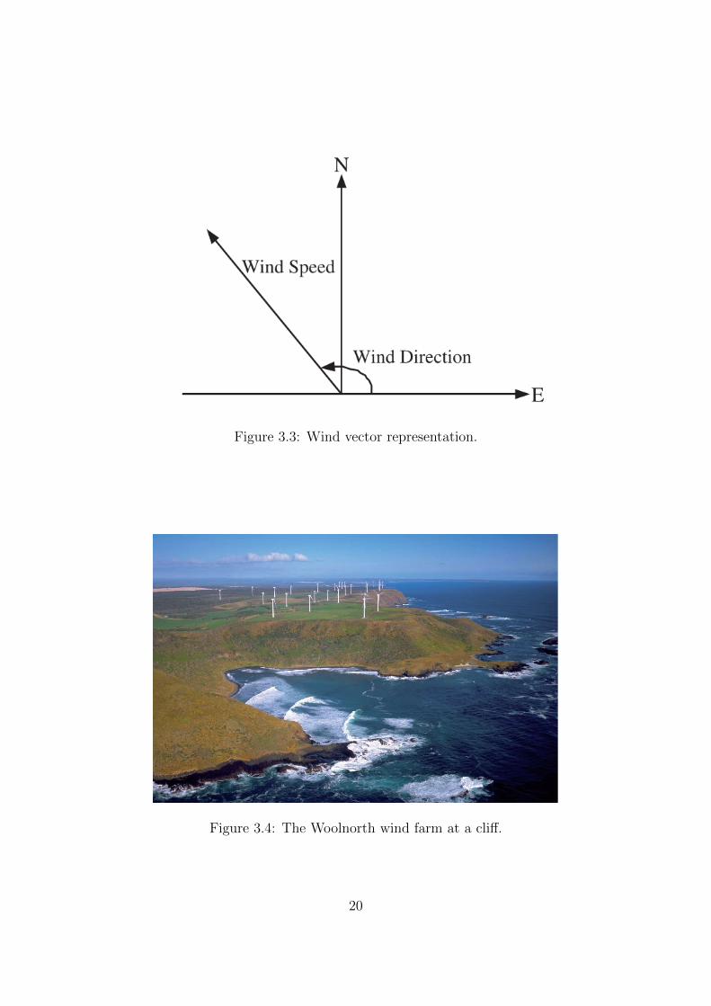
Figure 3.3: Wind vector representation.
Figure 3.4: The Woolnorth wind farm at a cliff.
20

x(k+1) [47]. Some of the major advantages of the MPC are its capability to handlethe constraints, its practical usage, and online optimization. Optimization methodin this study for minimizing (5.6) is dynamic programming algorithm subject to thesystem model (5.1) and constraints (5.7),(5.8),(5.10) with a given initial conditionfor (x1) and (x2).
In order to apply dynamic programming procedure firstly we introduced a func-tion
V (x1, x2,m) := minu(.)
N0+N∑k=N0
((r − u(k))2 (3.7)
In (3.7), r is the predicted wind power.We calculate this equation by complete search method, since −c5 ≤ x1 ≤ c5 ,c2 ≤ x2 ≤ c1 , we can take all x1, x2 with some small step ε > 0 for all 0 ≤ m ≤ N .The optimization problem at each step is solved using MATLAB.
3.4 Simulation
3.4.1 Database
In order to simulate the proposed control system in MATLAB software, actual windfarm data is being used. The data that selected as a case study in this simulationsgathered from Woolnorth wind farm power generation, which is located in Tasmania,Australia with the maximum capacity of 140 MW. These data are available in 5-minute resolution and is obtained from AEMO database [44].
3.4.2 Battery Type Selection
The battery which is used in this simulation is NaS battery (sodium-sulfur), becauseof its compatibility when it integrated to the wind power farm in comparison withother type of battery technologies. High efficiency (89%), high energy capacity andlong life span at 100% depth of discharge (DOD) up to 2500 cycles are some of itsremarkable features [12, 20]. Therefore, the data of NaS battery is gathered fromNGK insulators company [38].The energy capacity of this studied battery is 480MWh.
Table 3.1: Simulated Constraints Parametersc1 Upper bound of battery capacity 72 MWc2 Lower bound of battery capacity 8 MWc3 Maximum rated value of wind power 140 MWc4 Maximum ramp rate of wind power 1.4 MWc5 Maximum charging/discharging rated capacity 80 MW
21

Figure 3.5: Actual and smoothed power
3.4.3 Results and discussion
The simulation is carried out for one day (17th July 2010). For simplicity, predictionhorizon considered to be the same as control horizon to be 3 in the MPC algorithm(N = 3). Therefore, the prediction horizon assumed for this simulation is 15 minutesahead. Constrains are all chosen based on physical limitation as they are shown intable 5.3. The upper and lower bounds of battery capacity are selected as 90% and10% of 80 MW total capacity of battery (i.e., 72 MW and 8 MW). The maximumrated value of wind power is chosen as maximum generating capacity of Woolnorthwind farm (140 MW). Maximum Ramp rate is 1% of rated value in this simulation.Due to the battery type, the last constraint parameter is set as 80 MW. Simulationresults are shown in Fig. 3.5 - Fig. 3.8. Simulations performed using a predictedwind farm data and a nonlinear BESS model indicate that the performance of thiscontrol scheme is quite good; it smoothed the wind power data while keeping energycapacity of battery between its limitation. Due to the limited battery capacity, theoutput is not perfectly smoothed (Fig. 3.5). For instant, at time 7 am, the battery isfull charged (Fig. 3.6), therefore, the controller cannot keep the ramp rate within thedesired interval of [−c4, c4] (Fig. 3.7.b). The same phenomena is observed at time6 pm when battery is discharged. This means that meeting the battery constraintsprevents achieving the smoothed output. However, the output ramp rate is mostlylimited within the required boundaries (Fig. 3.7) compared to wind power ramp rate(Fig. 3.8). We define a metric to measure the smoothness, that is the fraction oftime in which the ramp rate resides in the required boundaries (i.e., [−0.01, 0.01]).The controller achieves a smoother output when the battery capacity constraint is
22

Figure 3.6: Battery energy capacity
Table 3.2: Measurement of SmoothnessBattery Capacity Constrain [10% 90%] [20% 80%] [30% 70%]Measurement of Smoothness 90% 84% 79%
less tight, for instant if the battery limit is set between 30% and 40% instead ofthe current setup (i.e., 10% and 90%), we expect result with more fluctuation inramp rate (less smoothness). In table 3.2 the measurement is shown for differentscenarios. The results in this chapter are presented in [48]
3.5 Conclusion
This study proposed a nonlinear battery model in order to integrate it with a windpower farm to smooth its output while the battery operates within a safe mar-gin. We simulated our control system using MPC based on dynamic programming.The controller performs well under tight realistic constraints taken from commercialplant ensuring the stability of the system. Wind power predictor with multiple ob-servation point can be improved and made more robust to unmodelled uncertaintiesusing the networked control systems approach of the papers [49–52]The proposedcontrol scheme is not limited to the wind power. It can also be leveraged for otherintermittent energy sources such as large scale photovoltaic solar farms. We plan toinvolve other important parameters such as energy price to maximize efficiency ofthe system while we benefit from all kind of available energy resources.
23

Figure 3.7: Ramp Rate for Wind power
24

Figure 3.8: Ramp Rate for Controlled Wind Power
25

Chapter 4
Maximizing Profit of a WindBattery Energy System UsingModel Predictive Control Drivenby a Dynamic Reference Policy
In this chapter we present a new control approach to manage the income by WindPower Plant (WPP) while it is intergraded with a Battery Energy Storage System(BESS). With the aid of this control strategy the WPP operator will be enabledto make a balance between energy supply and demand in a profitable way usingBESS. Furthermore, we demonstrate that there is a nonlinear relationship betweenbattery capacity and overall revenue and profit of WPP. Therefore, a suitable batterycapacity for a WPP should be chosen to achieve maximum revenue. In this study,the Controller is based on Model Predictive Control (MPC) theory using a dynamicprogramming algorithm along with a nonlinear battery energy storage model. Wepropose a selling policy model with two parameters by which the selling or saving ofwind power can be tuned accordingly to maximize the overall income of the WPP byapplying the electricity market pattern of Australia. Since the total profit dependson not only the selling policy but also other factors such as total battery capacity andcontrol techniques. Therefore, we also experiment the effect of battery capacity tomaximize the profit of the output power dispatched to the grid while using forecasteddispatch price and wind power. The efficiency of this control strategy is assessedunder different scenarios via simulations with actual data of wind farm and pricedata of NSW Australia. Reminder of the chapter is organized as follows. After abrief introduction in section 5.1, the problem description and control system designis provided in section 5.2. Following that, in section 5.3, the simulation results aregiven. Finally, the chapter is concluded in Section 5.4.
26

4.1 Introduction
In recent times, energy policies of worldwide are moving toward exploiting Renew-able Energy Sources (RES) such as the wind and solar energies. Since greenhousegas emission is caused by consumption of fossil energies, it persuades governmentsto motivate electricity plant operators to switch to the renewable sources. Moreover,increasing electricity demand and the crisis in fuel price in the world led us to utilizegreen resources.
However, due to the nature of these resources, there are some challenges ofapplying the wind or solar energies when they are planned to connect directly to thenetwork grid. In general, there are two main issues namely technical and financial.Some studies focused on technical difficulties of wind power plants and they figureout effective solutions to mitigate the risk of applying this type of RES [9,53,54]. Onthe other hand, some researchers emphasize on commercializing wind power outputwhen it is in the competitive electricity market [9,53,54]. In all these studies, batteryenergy storage system (BESS) is seen a reasonable solution that can be applied inwind farm plant to control the power by charging and discharging energy based onthe control signal command.
The works on smoothing the fluctuation of wind power output for its safe andreliable connection to the electricity grid vary from simple schemes of charging anddischarging the BESS as the wind power output goes beyond a minimum or max-imum threshold [55, 56] to much more sophisticated control algorithms [9, 53, 54].Specifically, The authors of [53] applied an optimal control method on the linearmodel of the leadacid battery to smooth the generated wind power and make itdispatchable on an hourly basis. They used one-hour ahead average forecasted windpower as the reference power to be dispatched. Also in [45] a prediction model forshort-term wind power forecasting was presented. In [9], an open-loop MPC schemewas proposed to find the optimal wind power output integrated with a BESS. Inthese studies, the prediction of wind power is based on a new model and the goal isthe reduction in the intermittency of wind power.
Some studies have been carried out to make wind power more commercial thanbefore by control the wind power while it is connected to the grid in presence ofBESS. Thus, BESSs enables wind energy to be stored during off peak demandtimes when the price of electricity is relatively low. Such stored energy can be soldsimultaneously with the power generated by the wind farm at peak demand timeswhen the price of electricity is higher. such dispatch schedules are highly dependenton firstly, the electricity market rules of the region where the power is sold, andsecondly, the constraints of the BESS.
For instance, the authors of [57] presented an economic and technical analysisfor hourly energy management of a wind farm with three different BESSs throughdetecting peak and off-peak electricity consumption periods. In another work, theprofitability of a wind power plant plus a BESS was examined from the supplychain perspective considering price volatility in the electricity market [58]. In [59],an iterative optimization technique for scheduling the wind power based on hourlyelectricity tariff prediction with a dual BESS structure was applied.
27

However, little attention has been paid to improve the controllability of windfarm dispatching with BESS in the area of control systems considering electricityprice and optimal use of BESS with the aim of providing the potential of tradingwithin a competitive electricity market while considering battery capacity effective-ness. In [20], an intelligent control system is implemented to manage the windpower injected to the grid using a BESS in time shifting application. In such previ-ous models which have been studied [9, 20], batteries were used as simple storagesthat linearly store the energy and did not take into account the losses inside thebattery as their chemical reactions. We consider a model based on its inputs andoutputs and consider a model which shows some nonlinear behaviors of the batteryduring charging, discharging and storing period.
In this paper, the main objective is to develop a control system based on modelpredictive control (MPC) combined with BESS, capable of generating a dynamicreference signal based on predicted price and wind data with any of intermittentenergy sources under certain limitations and constraints to increase the revenue ofwind power farm. A new control strategy for selling wind power energy to the gridwhile using non linear model of the battery is introduced in this study. The proposedcontrol system consists of two main components: (a) an active reference generatorblock and (b) an MPC based controller block. The application of this controllerwith an real-time reference generator in the design of the proposed control systemis a novel insight to the problem of controlling wind farm power which is integratedwith BESS.
The advantages of the proposed control system are as follows: real-time opti-mization of the overall system behavior and physical constraints handling using theMPC, adaptively updating the reference signal based on system states and predictedprice and wind power data, and improving the controllability of the wind farm powergeneration with the BESS into the electricity market while keeping the ramp rateof power signal inside the predefined barriers. Moreover, it is depicted that batterycapacity has highly affected on profit of the WPP. Therefore, choosing a suitableamount of battery for a specific WPP can improve the efficiency accordingly.
We test our controller with different scenarios based on the parameters usedin the proposed system. Finally we determine a battery capacity and values ofparameters to achieve the maximum profit for a given WPP. In order to illustratethe strength of the proposed methodology, we compare the results with other possiblesituations such as no-control or control with simple on-off policy which are explainedin this paper. The control system is simulated with real wind farm data fromWoolnorth wind farm site in Tasmania, Australia and the dispatch electricity pricedata of the New South Wales electricity market for the corresponding dates of thewind power generation. The wind farm is situated at a coastal site on a cliff whichgives the site a very high wind resource with extreme variations [42].
28

4.2 Problem Description
The key objective of this chapter is enhancement the benefits of wind power in theelectricity market. To archive this goal, a dynamic algorithm is designed to providea reference power signal which is capable of changing dynamically with the statusof the electricity price although satisfy the determined constraints simultaneously.Therefore, a control system which combined with a BESS is required to control thesignal that charges and discharges the battery to produce the desired power as closeas possible to the reference power signal.
4.2.1 Dynamic model of the system
In this study, we propose the following control system model for wind power energystorage system, {
x1(k + 1) = r(k)− u(k)
x2(k + 1) = f(x2(k)) + tdg(x2(k), u(k)),(4.1)
y(k) = x1(k) (4.2)
In (5.1), r(k) denotes as the production output of the farm, and let u(k) rep-resents as the power control command, i.e., for positive values of u(k) (u(k) > 0),the battery energy storage will be charged and it will be discharged for negativeones (u(k) < 0) and x2(k) is the current battery energy capacity. In (5.1), td isconversion coefficient (MW to MWh for each 5 min), i.e., td = 5min/60min = 1/12.This value is chosen based on Australian energy market operator (AEMO) [44]which defines 5min for power dispatch process. Therefore, each k step is 5 min(t = kh, k = 0, 1, 2, ..., and h = 5 is the sampling time in minutes).
4.2.2 Reference Generator
For any closed-loop control system, the reference signal or desired output shouldbe defined according to the desired requirements and the control objectives of thesystem [20]. Thus, we propose a decision-making system to generate the referencesignal. Our reference generator is dynamic and it is as a fraction of battery state,predicted wind power and predicted price. The decision-making system is mathe-matically expressed by,
yref (k) =
{r(k) + (2w(P )− 1)x2(k) w >= 0.5
r(k) + (2w(P )− 1)(x2max − x2(k)) w < 0.5(4.3)
where yref (k) is reference power signal, r(k) is predicted wind power and x2(k) isbattery available energy. w is the decision weight based on price and is expressed by,
w(P ) =1
1 + e−λ(P−P0)(4.4)
29

Figure 4.1: Fraction of available energy (Battery + Wind power) to be delivered tothe grid (2.w − 1) (P0 = 25).
It is the most convenient nonlinear exponential function of parameter λ. Theproposed decision system is based on two main concepts, (a) whenever the price ishigh, we deliver energy as much as possible to the grid (It means less storage andmore delivery) and (b) whenever the price is low, we store energy in the battery asmuch as possible (It means more storage and less delivery to the grid). To implementour decision-making system, we consider a fraction of available energy (Battery +Wind power) to be delivered to the grid and it is expressed by (2.w(P ) − 1). Wecall it ”Weight Function”. As it is shown in Fig. 4.1, it is an increasing function ofprice.
In (4.4), parameters λ and P0 are chosen by plant operator, which λ representsthe rate of storage/delivery based on our policy. P0 is called ”Hot Price” at whichwe neither store energy to nor extract from the battery. In other words, we want todeliver all energy generated by wind plant farm to the grid (yref (k)|P=P0). If P = 0then we store the wind into the battery till it gets fully charged and we deliverthe rest of energy to the grid. P is the predicted price that is determined by pricepredictor block which is explained in section 5.2.4. In Fig. 4.1, the behaviour of thisfunction for different λ is illustrated. We plot the weight fraction (2w(P )− 1) withP0 = 17($/MW ) and two values of λ. Red curve (corresponding to λ = 10 sharplyrises at P0 resulting an ”On-Off Policy” whereas the blue corresponding to λ = 0.3curve slightly increases in price represents a dynamic policy.
30

Reference Generator
Model Predictive Controller
Wind Power Plus BESS
Wind Power Predictor
Price Predictor
Time Interval
Wind Power
+
-
e
r
Figure 4.2: Block diagram of the proposed control system.
4.2.3 Wind Power Prediction Model
A wind farm prediction system is combined with the energy storage system to im-prove the overall performance of the control system. In this regard, we get short-termwind power prediction method in [45]. This model consists of two stages, the pre-diction of wind speed and direction which is achieved in the first stage and in thesecond stage, the predicted wind speed is converted to predicted output power.Thedata has a 5 min resolution and it is for 17th June 2010. The data is properlyfiltered by removing noise and any outliers.
4.2.4 Price Prediction
In our proposed control strategy, in order to generate the reference signal, we needa forecasted price for a short term ahead to enhance the benefit of the wind powerplant in deregulated market. There are several methods for forecasting the price fora short term period of time [60]. In this study we choose a simple autoregressive(AR) model which is used in [61]. In this stochastic model we use previous pricedata to forecast the price for future. We use following AR model,
pn(k + 1) = τp(k)pn(k) + ε(k) (4.5)
where, p(k) Average short price in week (k)pn(k) Normalized value of p(k)τp(k) Autocorrelation coefficientε(k) Normal random variable
4.2.5 Controller Design
MPC is based on the solution of an on-line optimal control problem where a recedinghorizon approach is utilized in such a way that for any current state x(k) at timek, an open loop optimal control problem is solved over some future interval takinginto account the current and future constraints. The algorithm of MPC computesan open loop sequence of the manipulated variables in a manner that the upcomingbehavior of the plant is optimized. Then we insert the first value of the optimizationinto the plant. This procedure is repeated at time (k + 1) using the current state
31

x(k+1) [47]. Some of the major advantages of the MPC are its capability to handlethe constraints, its practical usage, and online optimization.The structure of theproposed control system is illustrated in Fig. 4.2. Therefore, the proposed controllaw for the system in (5.1) will be obtained by minimizing the following cost function,
J :=
N0+N∑k=N0
((y(k)− yref (k))2 → min (4.6)
where N is prediction horizon. Optimization method in this study for minimizing(5.6) is dynamic programming algorithm subject to the system model (5.1) andfollowing constraints,
x2min ≤ x2(k) ≤ x2max (4.7)
−Umax ≤ u(k) ≤ Umax (4.8)
0 ≤ x1(k) ≤ c1 (4.9)
for all k ∈ 0, ..., N − 1 with a given initial condition for (x1) and (x2) as (x1(N0))and x1(N0) respectively. Physical concepts of constraints of proposed system hasbeen explained in brief in [9], [43], [20] and related references in these studies.The cost function (5.6) penalize the deviations of the reference power signal (yref (k))from the power output (y(k)) . There are some constraints which imposed by thissystem that indicated by (5.7), (5.8) and (5.10).The constraint (5.7) is chosen toavoid overloading or under loading of the battery i.e., the BESS should not bedischarged less than x2min or charged over x2max. Umax in (5.8) is the maximumcharging/discharging rated capacity of the battery. In order to keep the output ofthe system between 0 and rated value of the wind power (c1), constraint (5.10) isintroduced. In order to apply dynamic programming procedure firstly we introduceda function
J(x1, x2,M) := minu(.)
N0+M∑k=N0
((y(k)− yref (k))2 (4.10)
Where M is control horizon. We calculate this equation by complete searchmethod, since 0 ≤ x1(k) ≤ c1 , x2min ≤ x2(k) ≤ x2max, we can take all x1, x2 withsome small step ε > 0 for all 0 ≤ M ≤ N . For simplicity, wind power predictionin the MPC algorithm is used with control horizon to be the same as predictionhorizon and to be equal to three (N = M = 3).
First we assume that
J(x1, x2,M) := minu(.)
N0+M∑k=N0
{(y(k)− yref (k)}2
= minu(.){(y(N0)− yref (N0))2 + ....+ (y(N0 +M)− yref (N0 +M))2}.
(4.11)
We suppose that,
32

JN0 = y(N0)− yref (N0))2,
JN0+1 = y(N0 + 1)− yref (N0 + 1))2,
...
JM = y(N0 +M)− yref (N0 +M))2
(4.12)
As we want to optimise J(x1, x2,M) then we presume that
J∗N0,M = min{J∗
0,M−1 + JM},J∗N0,M−1 = min{J∗
0,M−2 + JM−1},...
J∗N0 = min{JN0}
(4.13)
In order to calculate J∗N0, we do a complete search for all x1, x2 by considering
their defined constrains to find y(N0) from our propose model (5.1) for all −Umax ≤u ≤ Umax with a small step ε. After finding an optimal value for J∗
N0 then we go tonext step to find J∗
N0+1 and this procedure continues to find J∗N0+M .
At the end of the optimization the optimal control signal sequence , uopt(k), willbe found for k = {N0, ..., N0 +M} that minimize the whole cost function (5.12).
uop = {uop(N0), uop(N0 + 1), ..., uop(N0 +M)} (4.14)
Then we choose the first value of this sequence (uop(N0)) as the first value ofthe optimization and apply it into the plant. This procedure is repeated at time(k+ 1) and in the new step N0 will be N0 + 1 and also current states ,according tothe model, will be x(k + 1) . This procedure is repeated for our whole trajectory.The optimization problem at each step is solved using MATLAB.
4.3 Simulations
In order to evaluate our control scheme, we apply our proposed model to actualwind and price data taken from the Woolnorth wind farm and AEMO, respectivelyand simulate in Matlab. Given wind and price at each sample time along with theprediction of these signals for next 3 sample times (N = M = 3), we generate ourreference signal. Then, we apply reference signal to our closed loop system (Fig. 4.2).We use dynamic programming in our controller to minimize the objective function(5.6).
4.3.1 Dataset
The wind power represent 1 day data and the maximum capacity of wind powergeneration is 140 MW. Also, the dispatch electricity price data of the New South
33

Table 4.1: Simulated Constraints Parametersx2max Upper bound of battery capacity 432 MWhx2min Lower bound of battery capacity 48 MWhc1 Maximum rated value of wind power 140 MWUmax Maximum charging/discharging rated capacity 80 MWc2 Maximum ramp rate of wind power 1.4 MW
Wales electricity market for the corresponding date of the wind power generation isselected. Price data is obtained from AEMO database [44]. Both wind power andprice data are available in 5-minute resolution.
4.3.2 Battery Type Selection
The battery which is used in this simulation is NaS battery (sodium-sulfur), becauseof its compatibility when it integrated to the wind power farm in comparison withother type of battery technologies. High efficiency (89%), high energy capacity andlong life span at 100% depth of discharge (DOD) up to 2500 cycles are some of itsremarkable features [12, 20]. Therefore, the data of NaS battery is gathered fromNGK insulators company [38].The energy capacity of this studied battery is 480MWh. We use battery model parameters as follows,
α = 0.98, β = 0.95, γ = 1.05, Mc = 54MW and Md = −37MW
Figure 4.3: Sodium-Sulfur (NaS) Battery Structure
4.3.3 Results
For simplicity, prediction horizon is considered to be the same as control horizonin the MPC algorithm (i.e. N = M = 3). Therefore, the prediction horizon isassumed for this simulation to be 15 minutes ahead. Constrains are all chosenbased on physical limitation as they are shown in table 5.3. The maximum ratedvalue of wind power (c1) is chosen as maximum generating capacity of Woolnorthwind farm (140 MW). Due to the battery type, the constraint parameter (Umax) isset as 80 MW. Simulation results are shown in Fig. 4.4 - Fig. 4.21. Since our study
34

Figure 4.4: Wind power data for one day.
of MPC is more price constrict, therefore our reference generator highly depends onchoice of hot price namely (a) low hot price (i.e. 20$/MW ), (b) moderate hot price(25$/MW ) and (c) high hot price (30$/MW ). Primary results in this chapter arepresented in [62].
Low hot price
In this case, we expect to dispatch more power to the network since the hot priceis chosen low enough to affect the control system releasing the energy more often.As it is shown in Figs. 4.6,4.7,4.8, during 4 am and 7 pm, system stores energy inthe battery as much as possible till it reaches to the full capacity and then from 7am that price goes more than 20$, controller command the system to release moreenergy to the grid and use the battery capacity as a back up. The same trendhappens during 1 am and 4 am next day.
Moderate hot price
When the operator choose moderate hot price (25$/MW ), controller use the batteryto store energy more often than first case scenario (Low hot price) and as it isdepicted in Figs.4.9,4.10,4.11, during 4 am and 9 am, most part of the wind powerstored in the battery. After fully charge the battery, the rest of the wind powerwill be sent to the grid. If there was not any concern about battery costs and wecould apply unlimited capacity in the proposed system, then all the wind powerproduction had been stored in the battery according to the defined rules between 4
35

Figure 4.5: Price data for one day
Figure 4.6: Results when Hot price is 20 $ per MWh: Reference and output powersignal.
36

Figure 4.7: Results when Hot price is 20 $ per MWh: Battery’s state.
Figure 4.8: Results when Hot price is 20 $ per MWh: Control input or charg-ing/dicharging power of the battery
37

Figure 4.9: Results when Hot price is 25 $ per MWh: Reference and output powersignal.
am and 9 am.
High hot price
High hot price is defined for specific conditions where there is enough capacity andalso the owner of the wind power plant prefer to sell the energy with high price incompare with the other scenarios . In this case study, majority of time the price islower than high hot price and therefore controller send signal to the system to storethe energy as much as the capacity allow to the system. As in this particular studythe capacity is same as two above scenarios, it is shown in Figs. 4.12,4.13,4.14 thatbetween 4 am to 7pm, the battery is fully charged and rest of the wind power willbe sent to the grid. After a pick during 7pm and 8pm again system come back toits previous status.
4.3.4 Impact of dynamic storage policy
The Impact of parameter λ on revenue
Fig. 4.18 shows plant revenue for two weeks when λ changes from 0.1 to 10 (inthe dashed blue curve). The solid red curve represents the total revenue while nobattery is presented on the plant which means that the wind power is completelydispatched without any control. As it is depicted, maximum of revenue occurs atλ = 0.6 reaching to 715k$ that results 47% improvement in revenue compared to thebaseline (which represents no control scenario). We can see that the revenue falls
38

Figure 4.10: Results when Hot price is 25 $ per MWh: Battery’s state.
Figure 4.11: Results when Hot price is 25 $ per MWh: Control input or charg-ing/dicharging power of the battery
39
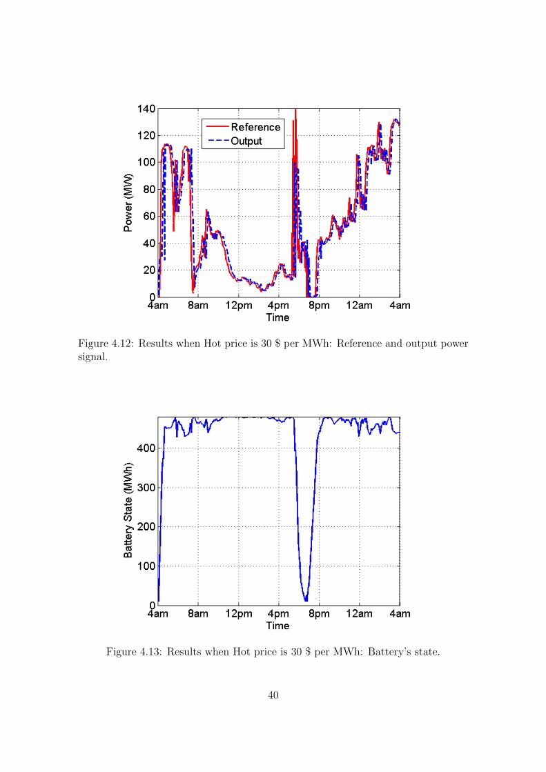
Figure 4.12: Results when Hot price is 30 $ per MWh: Reference and output powersignal.
Figure 4.13: Results when Hot price is 30 $ per MWh: Battery’s state.
40

Figure 4.14: Results when Hot price is 30 $ per MWh: Control input or charg-ing/dicharging power of the battery
Figure 4.15: Weight fraction for three different Hot Prices: Hot Price =20.
41

Figure 4.16: Weight fraction for three different Hot Prices: Hot Price =25.
Figure 4.17: Weight fraction for three different Hot Prices: Hot Price =30.
42

after this point since increasing the λ causes the storage policy to become similarto ”on-off” scenario . From λ = 3 we can observe that the revenue is stabilized.Note that at large λ (for instance λ = 10) the revenue is higher than the situationin which no battery is applied on the WPP. In Fig. 4.19 zoomed-in range of λ(0.1 <= λ <= 10) is depicted to specify the main changes of λ.
Figure 4.18: The Impact of parameter λ on revenue (Large Range of λ (0.1 <=λ <= 10))
Impact of Battery Capacity
In order to investigate the impact of battery capacity on the revenue of the system,we simulated a sample data of two weeks for a range of 100 to 750 MWh batterycapacities for three different λ (λ = 0.1, 0.6, 10). It was expected that there should bea linear relationship between battery capacity and revenue of the system. However,simulated results in Fig. 4.20 show that the trend is nonlinear. It was clarified inchapter 3 that battery has some leakages during charging and discharging processes.Therefore, by increasing the capacity, cycle of charging and discharging will growup and consequently the higher amount of power will be lost. However, since thissimulation has been done for a specific WPP, it is experienced that by increasingthe battery capacity to 750MWh, not only there is no more rising in the revenue ofthe WPP, but also some dropping happened in revenue.
43

Figure 4.19: The Impact of parameter λ on revenue (Zoomed-in range of λ (0.1 <=λ <= 1)).
Joint Impact of λ and capacity
As we have seen, the total revenue is a function of two main variables namely λ andbattery capacity. We plot the joint impact of these two drivers on the revenue in a3-D diagram shown in Fig. 4.21. It can be observed that global maximum of revenueis perceived at λ = 0.6 and battery capacity 600 MWh. Note that this graph is quiteuseful for plant operators to strategize their profitable region of operation. Table4.2 summarizes the system parameters including two weeks revenue correspondingto different battery energy storage capacities with a fix λ.
Table 4.2: System parameters: variable battery energy storage capacity.
Capacity(MWh)
λ Max Ca-pacity
Min Ca-pacity
InitialCapac-ity
TwoWeeksProfit(K$)
100 0.6 90 10 50 61.9
300 0.6 270 30 150 568.2
400 0.6 360 40 200 661.6
600 0.6 540 60 300 932.3
44

Figure 4.20: Impact of battery capacity on revenue on WPP
4.4 Summary
In this study, a novel control scheme has been proposed to manage the amount ofenergy which is generated and sold to the electricity market with respect to plantand battery constraints. we considered two objectives: (1) empowering the operatorto make a balance between energy supply and demand in a profitable way usingbattery storage; and (2) maximizing the total revenue of the WPP with the aid ofchoosing appropriate battery capacities in compliance with the capacity of WPP. We simulated our control system using MPC based on dynamic programming.The controller performs well under tight realistic constraints taken from commercialplant ensuring the stability of the system.The proposed control scheme is not limitedto the wind power. It can also be leveraged for other intermittent energy sourcessuch as large scale photovoltaic solar farms.
45

Figure 4.21: Joint impact of λ and capacity
46

Chapter 5
A Simulation Study on Impact ofMonotonic BatteryCharging/Discharging on Cost andRevenue of Wind Power Plant
The charging/discharging behavior of battery has a significant impact on both costand revenue of wind power plant (WPP). It has been shown that monotonic charg-ing/discharging strategy has reduced the capital cost of WPP. In this chapter, wepresent a control approach to manage the income of WPP while we combine themonotonic charging/discharging methodology to our system design. The Controlleris based on Model Predictive Control (MPC) theory using a dynamic programmingalgorithm along with a nonlinear battery energy storage model. We exploit theeffect of charging/discharging pattern of the battery to maximize the profit of theoutput power dispatched to the grid while using forecasted dispatch price and windpower. This chapter is organized as follows. Section 6.1 gives a brief introduction.In section 6.2 problem statement is illustrated. Following that, in section 6.3, themonotonic charging/discharing strategy is expressed, in section 6.4 the proposedcontrol system and the controller design are described. The simulation results aregiven in Section 6.5. Finally, the chapter is concluded in Section 6.6. The efficiencyof this control strategy is assessed under different scenarios via simulations withactual wind farm data and NSW Australia price data.
5.1 Introduction
Diverse methods are offered in implementing BESS integrated with wind powerplan in order to increase the revenue of WPP. Depends on regulated (fixed tariffs)or deregulated markets (variable tariffs), different techniques are presented. In abasic scenario, energy is stored in the duration of off-peaks and is delivered at peaktimes in the regulated markets such as Australian electricity market regulations. Onthe other hand, in the regulated markets for renewable energy productions, simpler
47

strategies can be proposed to enhance the performance of WPP with the aid ofBESS. In this regards, the author of [4] applied a sophisticated control algorithm tomanage the hybrid wind power with a constraint optimizer based on the assumptionof deregulated market. In [4] a management energy system is designed while storagecost factor is considered. The rule of BESS is essential in all these practical andtheoretical studies. Therefore, research on improving the performance of integratingBESS should be considered as the main subject to not only decrease the capital costsof WPP but also increase the total revenue of selling wind power output.
Due to the latest improvement in technology of battery in the market of batteryindustry, variety of batteries are provided by companies in this area. The cost ofbattery especially in large scales is one of the main factors for customers. One of theapplications of BESSs in large scale is in wind power industry. Charging/dischargingstrategy highly effects on a lifetime of batteries and consequently affect directly ontotal costs of the plant which is used. Furthermore, the size of the battery is anotherparameter which can result in decreasing price of the battery.
Therefore, to improve the lifetime and cost of the battery some studies emphasison designing strategies to enhance the performance of BESS while it is connected toWPP. For instance, in [63], a constrained monotonic charging/discharging strategyis presented in order to reduce the ramp rate of wind power in respect to the optimalcapacity of battery energy storage. In this study, revenue of the plant has not beeninvestigated. Also in [9, 20, 63], batteries assume as simple storages that linearlystore the energy and did not take into account the losses inside the battery astheir chemical reactions. We consider a model based on its inputs and outputsand consider a model which shows some nonlinear behaviors of the battery duringcharging, discharging and storing period.
In this chapter, we focus on developing a control strategy to maximize the revenueof WPP while BESS is combined with the system. Meanwhile, we employ themonotonic charging and discharging strategy to not only optimise the capacity ofBESS but also enhance the life time of battery simultaneously. We examine the effectof applying the presented strategy in [63] on the revenue of WPP. The proposedcontroller is examined with real wind farm data from Woolnorth wind farm site inTasmania, Australia and the dispatch electricity price data of the New South Waleselectricity market for the corresponding dates of the wind power generation.
5.2 Problem Statement
In this chapter we focus on maximizing wind power plant revenue while WPP isintegrated with BESS. Indeed, we employ a strategy that consider the future stateof both energy price and wind power by which a reference signal will be dynamicallygenerated. A novel approach in this chapter is emphasising on optimal capacityof BESS by applying monotonic charging and discharging strategy. Therefore, acontrol system which combined with a BESS is required to control the signal thatcharges and discharges the battery to produce the desired power as close as possibleto the reference power signal.
48

5.3 Monotonic charging/discharging methodology
In [63], a monotonic chaging/dishcaging statutory has been presented to smoothout the fluctuated wind power produced by wind power plant. In this paper weinvestigate the reflection of applying this method on revenue of the WPP. Since thismethod plays a fundamental rule in this research, we elaborate it in this section. Inthis regard we
5.4 Control System Design Description
5.4.1 Dynamic Model of the System
The following nonlinear dynamic equations are proposed based on the system struc-ture in chapter 3: {
x1(k + 1) = r(k)− u(k)
x2(k + 1) = f(x2(k)) + tdg(x2(k), u(k)),(5.1)
y(k) = x1(k) (5.2)
where x1 or pg(k) in Fig.5.2 is the power which is sent to the grid, x2(k) isthe battery energy capacity at time step k, r(k) is the uncontrolled wind poweroutput, u(k) or pc is power control signal in case of positive values (u(k) >= 0)and for negative values of u(k) (u(k) < 0)the battery is charged and dischargedrespectively. td is a factor to convert MW to MWh. In (5.1),functions f and g aredefined to represent the nonlinear behaviour of the battery as below:
f(x) = α(x)x (5.3)
and,
g(x, u) =
β(x)Mc for u > Mc
β(x)u for 0 ≤ u ≤Mc
γ(x)u for Md ≤ u < 0
γ(x)Md for u < Md
(5.4)
with following constraintsf(x(k)) ≤ x(k) ∀ x(k)
g(x(k), 0) = 0 ∀ x(k)
g(x(k), u(k)) ≤ u(k) ∀ x(k), u(k)
(5.5)
In order to reflect the real behaviour of battery during charging/dischaging andstoring periods, functions f and g are presented. Based on defined function In 5.3,
49
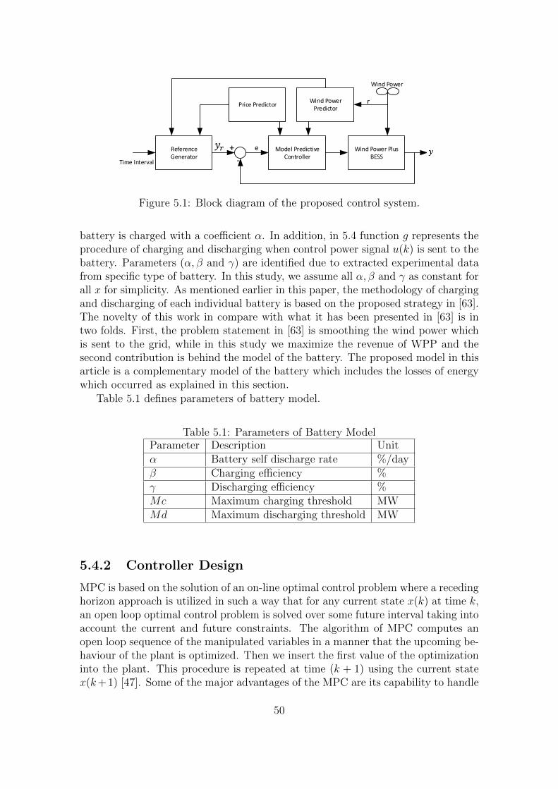
Reference Generator
Model Predictive Controller
Wind Power Plus BESS
Wind Power Predictor
Price Predictor
Time Interval
Wind Power
+
-
e
r
Figure 5.1: Block diagram of the proposed control system.
battery is charged with a coefficient α. In addition, in 5.4 function g represents theprocedure of charging and discharging when control power signal u(k) is sent to thebattery. Parameters (α, β and γ) are identified due to extracted experimental datafrom specific type of battery. In this study, we assume all α, β and γ as constant forall x for simplicity. As mentioned earlier in this paper, the methodology of chargingand discharging of each individual battery is based on the proposed strategy in [63].The novelty of this work in compare with what it has been presented in [63] is intwo folds. First, the problem statement in [63] is smoothing the wind power whichis sent to the grid, while in this study we maximize the revenue of WPP and thesecond contribution is behind the model of the battery. The proposed model in thisarticle is a complementary model of the battery which includes the losses of energywhich occurred as explained in this section.
Table 5.1 defines parameters of battery model.
Table 5.1: Parameters of Battery ModelParameter Description Unitα Battery self discharge rate %/dayβ Charging efficiency %γ Discharging efficiency %Mc Maximum charging threshold MWMd Maximum discharging threshold MW
5.4.2 Controller Design
MPC is based on the solution of an on-line optimal control problem where a recedinghorizon approach is utilized in such a way that for any current state x(k) at time k,an open loop optimal control problem is solved over some future interval taking intoaccount the current and future constraints. The algorithm of MPC computes anopen loop sequence of the manipulated variables in a manner that the upcoming be-haviour of the plant is optimized. Then we insert the first value of the optimizationinto the plant. This procedure is repeated at time (k + 1) using the current statex(k+1) [47]. Some of the major advantages of the MPC are its capability to handle
50

the constraints, its practical usage, and online optimization.The structure of theproposed control system is illustrated in Fig. 5.1. Therefore, the proposed controllaw for the system in (5.1) will be obtained by minimizing the following cost function,
J :=
N0+N∑k=N0
((y(k)− yref (k))2 → min (5.6)
where N is prediction horizon. Optimization method in this study for minimizing(5.6) is dynamic programming algorithm subject to the system model (5.1) andfollowing constraints,
x2min ≤ x2(k) ≤ x2max (5.7)
−Umax ≤ u(k) ≤ Umax (5.8)
0 ≤ x1(k) ≤ c1 (5.9)
−c2 ≤ x1(k)− x1(k − 1) ≤ c2 (5.10)
for all k ∈ 0, ..., N − 1 with a given initial condition for (x1) and (x2) as (x1(N0))and x1(N0) respectively .The cost function (5.6) penalize the deviations of the reference power signal (yref (k))from the power output (y(k)) . There are some constraints which imposed by thissystem that indicated by (5.7), (5.8) and (5.10).The constraint (5.7) is chosen toavoid overloading or under loading of the battery i.e., the BESS should not bedischarged less than x2min or charged over x2max. Umax in (5.8) is the maximumcharging/discharging rated capacity of the battery. In order to keep the outputof the system between 0 and rated value of the wind power (c1), constraint (5.10)is introduced. Constraint (5.10) is defined to control the degree of smoothing. Itdescribes the difference between two consecutive amounts of smoothed wind power.
In order to apply dynamic programming procedure firstly we introduced a func-tion
J(x1, x2,M) := minu(.)
N0+M∑k=N0
((y(k)− yref (k))2 (5.11)
Where M is control horizon. We calculate this equation by complete search method,since 0 ≤ x1(k) ≤ c1 , x2min ≤ x2(k) ≤ x2max, we can take all x1, x2 with some smallstep ε > 0 for all 0 ≤ M ≤ N . For simplicity, wind power prediction in the MPCalgorithm is used with control horizon to be the same as prediction horizon and tobe equal to three (N = M = 3).
First we assume that
J(x1, x2,M) := minu(.)
N0+M∑k=N0
{(y(k)− yref (k)}2
= minu(.){(y(N0)− yref (N0))2 + ....+ (y(N0 +M)− yref (N0 +M))2}.
(5.12)
51

Figure 5.2: Diagram of a sample grid which is connected with a wind farm plusalong with BESS
We suppose that,
JN0 = y(N0)− yref (N0))2,
JN0+1 = y(N0 + 1)− yref (N0 + 1))2,
...
JM = y(N0 +M)− yref (N0 +M))2
(5.13)
As we want to optimise J(x1, x2,M) then we presume that
J∗N0,M = min{J∗
0,M−1 + JM},J∗N0,M−1 = min{J∗
0,M−2 + JM−1},...
J∗N0 = min{JN0}
(5.14)
In order to calculate J∗N0, we do a complete search for all x1, x2 by considering
their defined constrains to find y(N0) from our propose model (5.1) for all −Umax ≤u ≤ Umax with a small step ε. After finding an optimal value for J∗
N0 then we go tonext step to find J∗
N0+1 and this procedure continues to find J∗N0+M .
At the end of the optimization the optimal control signal sequence , uopt(k), willbe found for k = {N0, ..., N0 +M} that minimize the whole cost function (5.12).
uop = {uop(N0), uop(N0 + 1), ..., uop(N0 +M)} (5.15)
Then we choose the first value of this sequence (uop(N0)) as the first value ofthe optimization and apply it into the plant. This procedure is repeated at time(k+ 1) and in the new step N0 will be N0 + 1 and also current states ,according tothe model, will be x(k + 1) . This procedure is repeated for our whole trajectory.The optimization problem at each step is solved using MATLAB.
52
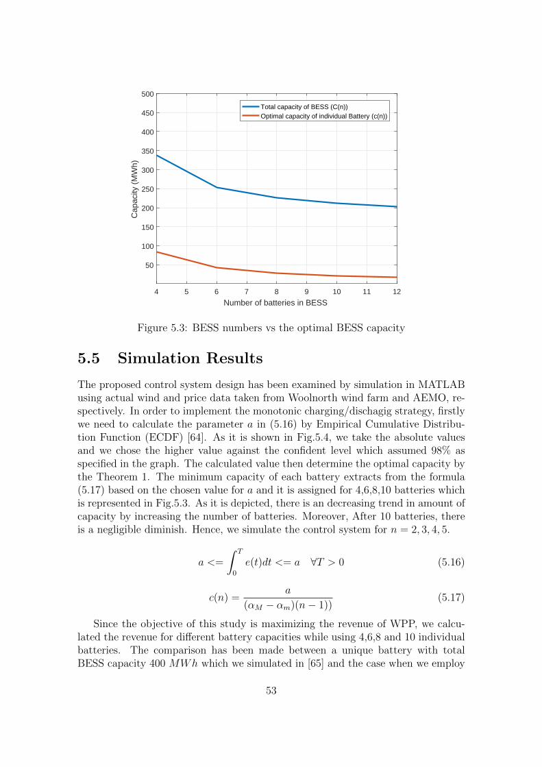
4 5 6 7 8 9 10 11 12
Number of batteries in BESS
50
100
150
200
250
300
350
400
450
500
Cap
acity
(M
Wh)
Total capacity of BESS (C(n))Optimal capacity of individual Battery (c(n))
Figure 5.3: BESS numbers vs the optimal BESS capacity
5.5 Simulation Results
The proposed control system design has been examined by simulation in MATLABusing actual wind and price data taken from Woolnorth wind farm and AEMO, re-spectively. In order to implement the monotonic charging/dischagig strategy, firstlywe need to calculate the parameter a in (5.16) by Empirical Cumulative Distribu-tion Function (ECDF) [64]. As it is shown in Fig.5.4, we take the absolute valuesand we chose the higher value against the confident level which assumed 98% asspecified in the graph. The calculated value then determine the optimal capacity bythe Theorem 1. The minimum capacity of each battery extracts from the formula(5.17) based on the chosen value for a and it is assigned for 4,6,8,10 batteries whichis represented in Fig.5.3. As it is depicted, there is an decreasing trend in amount ofcapacity by increasing the number of batteries. Moreover, After 10 batteries, thereis a negligible diminish. Hence, we simulate the control system for n = 2, 3, 4, 5.
a <=
∫ T
0
e(t)dt <= a ∀T > 0 (5.16)
c(n) =a
(αM − αm)(n− 1))(5.17)
Since the objective of this study is maximizing the revenue of WPP, we calcu-lated the revenue for different battery capacities while using 4,6,8 and 10 individualbatteries. The comparison has been made between a unique battery with totalBESS capacity 400 MWh which we simulated in [65] and the case when we employ
53

0 10 20 30 40 50 60 70 80a
0
0.1
0.2
0.3
0.4
0.5
0.6
0.7
0.8
0.9
1
F(a)
Empirical CDFX: 67.69Y: 0.998
Figure 5.4: The ecdf of absolute values of error signal in (5.16)
Table 5.2: Comparison of Revenue for BEESsNumber of Battries 1 4 6 8 10Capacity (MWh) 400 338 253 225 211Revenue (K$) 661 615 541 530 516
individual batteries based on the Theorem 1 which specified in section 6.3. It is il-lustrated in Table.5.2 that in case of using 2n batteries with total capacity of C(n),the revenue is slightly lower than using a single battery of capacity 400MWh. Incontrast, the capital cost of WPP is decreased dramatically by increasing the num-ber of batteries in BESS. Therefore, although there is a reduction in total revenueof the WPP, a huge saving will be archived in capital cost of WPP by applying theproposed strategy in [63],
Fig.5.6 shows the monotonic behaviour of battery during charging and discharg-ing process for 4 batteries. In this regard, we observe a reduction in number of cyclesof each battery in compare with the case of using of one battery with capacity ofC(n). Aa s result, the lifetime of battery improves.
To display the performance of the proposed control system design, Fig.5.7 indi-cates that the output of the closed loop system (Fig. 5.1) follows the reference powerwhich is generated by (4.3) in an acceptable way(with average error of (1.2%). Bat-tery model parameters which is utilized in this case study are as follows, α = 0.98,β = 0.95, γ = 1.05, Mc = 1.5 ∗ c(n) and Md = −2.1 ∗ c(n).
54
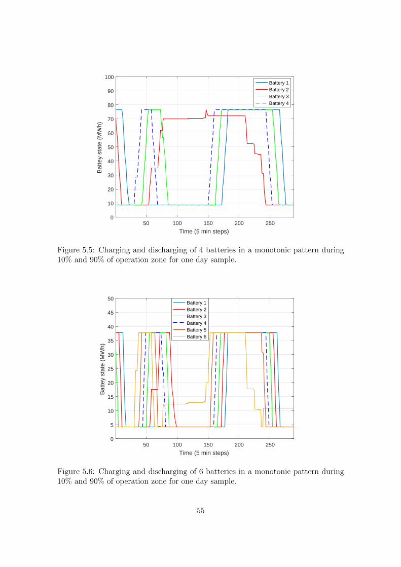
50 100 150 200 250
Time (5 min steps)
0
10
20
30
40
50
60
70
80
90
100
Bat
tey
stat
e (M
Wh)
Battery 1Battery 2Battery 3Battery 4
Figure 5.5: Charging and discharging of 4 batteries in a monotonic pattern during10% and 90% of operation zone for one day sample.
50 100 150 200 250
Time (5 min steps)
0
5
10
15
20
25
30
35
40
45
50
Bat
tey
stat
e (M
Wh)
Battery 1Battery 2Battery 3Battery 4Battery 5Battery 6
Figure 5.6: Charging and discharging of 6 batteries in a monotonic pattern during10% and 90% of operation zone for one day sample.
55

4am 8am 12pm 4pm 8pm 12am 4amTime
0
50
100
150
Pow
er (
MW
)
ReferenceOutput
Figure 5.7: Reference and output reference signals for one day in 5-mins timessteps.(p = 20$/MWh and λ = 0.6.)
Table 5.3: Simulated Constraints Parametersx2max Upper bound of capacity
for each battery10%c(n) MWh
x2min Lower bound of capacityfor each battery
90%c(n) MWh
c1 Maximum rated value ofwind power
140 MW
Umax Maximum charg-ing/discharging ratedcapacity
20%c(n) MW
c2 Maximum ramp rate ofwind power
1.4 MW
5.6 Conclusion
A control strategy to maximize the revenue of WPP in presence of monotonic charg-ing/discharging strategy has been studied while BESS was integrated with WPP. Ithas been investigated the effect of monotonic charging/discharging methodology onthe cost of the battery as well as revenue of WPP. The simulation results demon-strate a minor reduction in revenue of wind power plant by decreasing the totalbattery capacity while we employed optimal size of BESS based on the Theorem ex-plained in section 6.3. Furthermore, the outcomes show the improvement in lifetime
56

of battery by reducing cycle numbers of charging and discharging of each individualbattery. The proposed control scheme is not limited to the wind power. It can alsobe leveraged for other intermittent energy sources such as large-scale photovoltaicsolar farms.
57

Chapter 6
Conclusions and Future Works
High penetration of wind power energy in the electricity network grid as a resultof reducing the consumption of fossil fuels by governments, encourages researchersand industries to emphasise their effort to not only improve technologies related tothe wind power plants but also to enhance the efficiency of its output, technicallyand financially by employ control theories. Comprehensive literature review on thistopic disclosed that energy storage system is the best tool in hand of control theoriesto change the wind power to a reliable source of energy technically by reducingits fluctuation and financially it helps to raise its total revenue in the competitiveelectricity market. Background studies also revealed that among a variety of energystorage technologies, batteries are the best match with wind power plants since theirsize and charging/discharging methodologies. Therefore, in this report, we focusedon employing battery energy storage with a new model in wind power plant witha new control strategy to mitigate the challenges related to this attractive greenenergy.
6.1 Conclusions
Since the battery plays a fundamental role in this research, we firstly designed anew generic model in chapter 3 which is applicable to all type of batteries. Thisnew nonlinear battery model captures chemical processes and physical features of areal battery. The model was developed to improve the accuracy of control designingby considering the real property of the battery in the modelling of the system.In previous models, it was needed to investigate equations of chemical reactionsinside the battery and there was a complicated procedure to figure out the electricalmodel of the battery. However, using the proposed model in this report, we can easilychange the parameters to obtain a new type of battery based on real data from eitherexperimental result or data from the manufacturer of the battery. Parameters ofthe proposed model are totally dependent on different factors that are explained inchapter 3 in details. In order to simplify the battery model in some control designs,there should be some assumptions such as no variations in temperature which hasbeen considered in this study.
58

In chapter 4, we presented a wind power smoothing model. We employed anonlinear battery model long with a model predictive control technique and applyingdynamic programming as an optimization tool to smooth the natural intermittencyin the wind power output. The Battery energy storage system (BESS) has been usedin many control systems. The purpose of choosing Model Predictive Controller is itscapability in handling physical constraints of wind power system (such as batterycharging/discharging rate, maximum and minimum rated value of wind power, lowerand upper bounds of battery capacity). This controller exploits the inputs from theprediction model which has been embedded in the proposed system in its predictiveoptimization enhancing the overall performance of the system. The final simulationresults showed that the controller worked well under forced practical constraints andit could reduce the ramp rate of output wind power. The data that was used inthis case study was obtained from one of real wind farm plants located in Australia.Since this model is flexible compared to other renewable energy sources, the controlcan be utilized on solar plants as another major source of green energy.
In chapter 5, we emphasize on wind power plant from the financial point ofview. We presented a new control approach to increase the overall income of atypical wind power plant. Therefore, we proposed a mathematical formula to createa reference signal for a closed-loop system based on an idea of selling more energyduring the time in which the electricity price is higher. The controller is MPC-basedand the BESS model implemented in the system is nonlinear. Optimal operationof the system is tested under tight constraints of the real system. Both predictedprice and wind power inputs have been inserted into the control system to maximizethe income of WPP. The control strategy is based on Australian Electricity Marketwhich is a non-fixed tariff. For other types of electricity markets [66] for renewableenergies that exist in the works such as fixed-tariff in Canada, this control strategycan be modified by presenting another methodology in the reference signal. Thecontroller and the model can be applied without any changes for those systems.
Finally, in chapter 6, the optimal capacity of battery energy storage in compli-ance with the controller design has been investigated. In this regard, a monotoniccharging/discharging strategy [63] has been applied to the control system to increasethe lifetime of the battery and also decrease the capacity of BESS. The output re-sults of using the optimal capacity methodology revealed that the total capacity ofBESS was significantly reduced (much less capital expenditure), though we observeda little reduction in the total revenue of wind power plant. In other words, smallercapacity has a major effect on total cost of wind power plant and it can be goodmotivation for owners of wind power plants to apply this optimal strategy combinedwith the control system designed in chapter 5 to improve the total performance oftheir system technically and financially.
6.2 Future works
In the generic nonlinear model of the battery, we put aside the temperature effect onthe parameters of the systems. Although in normal situations, we can assume that
59

the temperature does not have large fluctuation, the variation of ambient tempera-ture can influence the performance of the battery [30, 31, 67]. Therefore, it can beuseful to insert the effect of this phenomena in the design of our model. In addition,the charging and discharging efficiency factors which introduced in chapter 3 canbe varied based on the rate of charging and discharging. Therefore, to improve theprecision of the model, it is more realistic to consider these coefficients as depen-dent rather than constant. The mathematical equation of these relations shouldbe investigated in future works. The estimation and selection of model parametersmay be improved using advanced intelligent techniques instead of intensive empiricalstudies.
In the smoothing model of wind power plant, the proposed model can be testedfor other types of green energies such as solar power. However, some changes shouldbe applied to the model to be matched with that specific renewable energy. Sincesolar panels recently are being popular especially in small scales such as home us-ages [68, 69], it may be useful to apply our control strategy to reduce the short-comings of this source of energy. Batteries in small sizes can be controlled by ourproposed strategy for home usages on beside of solar panels. In general, to enhancethe overall performance of the control system, further study is essential on the ro-bustness, uncertainty and noise effects in future works. Another direction of futureresearch is to improve the quality of our modelling by using robust model valida-tion and Kalman state estimation techniques such as in [49, 70–73]. For control ofBESS modelled as a system with uncertainties, we will need to use more advancedmethods of modern robust control such as H-infinity based control design [74–77],robust switched controllers [78–82] and sliding mode control [83–87]. Despite thefact of recent developments of wind power plants in large-scale and increasing itspopularity in all countries [3], it has caused various issues of profitability in compet-itive electricity markets. Hence, complicated price prediction models are needed incompliance with wind power prediction systems to grow the revenue of wind powerplant. Each country has its unique electricity market rules [66,88], thus we suggest adynamic prediction model to satisfy these differences. Also, large prediction horizonmay help to have a better performance on the control outcomes. Combination oflifetime model of battery by considering technical parameters mentioned in [89, 90]with the designed battery model can help in control design to increase the lifetimeof batteries. Then it can then incorporated into the cost function of the MPC as oneof the parameters for optimal operation of the BESS. One of the approaches to esti-mate the lifecycle of BESS is known as ”Rainflow Cycle Counting” [91]. Therefore,finding a model for the BESS lifecycle and including it in the optimization problemis an interesting future line of research.
BESS expenses always are a big concern for investors in renewable energy plants.We suggest to consider the battery cost for each charging and discharging cycle inthe control system design and the cost function ;however, this cost value is nontrivialand can change the overall control strategy [92]. In chapter 6 we studied the effect ofoptimizing battery capacity on revenue of wind power plant. By considering the costof battery per kw, we may reach to a more realistic overview for measuring the netrevenue for wind power plant. In future studies, we recommend to calculate the cost
60

of BESS per kw in the energy modeling of the system to improve its accuracy [92].Another direction of future research will be extension of some of the results
of this report to the case of decentralized BESS where each battery has its owncontroller with limited communication to other batteries. In this problem, we willuse distributed storage framework of [93,94] that is based on the concept of consensusin multi-agent systems [95–97].
61

Bibliography
[1] S.-P. Breton and G. Moe, “Status, plans and technologies for offshore windturbines in europe and north america,” Renewable Energy, vol. 34, no. 3, pp.646 – 654, 2009.
[2] M. Sathyajith, Wind energy: fundamentals, resource analysis and economics.Springer, 2006.
[3] P. Zou, Q. Chen, Y. Yu, Q. Xia, and C. Kang, “Electricity markets evolutionwith the changing generation mix: An empirical analysis based on china 2050high renewable energy penetration roadmap,” Applied Energy, vol. 185, pp.56–67, 2017.
[4] H. H. Abdeltawab and Y. A.-R. I. Mohamed, “Market-oriented energy man-agement of a hybrid wind-battery energy storage system via model predictivecontrol with constraint optimizer,” IEEE Transactions on Industrial Electron-ics, vol. 62, no. 11, pp. 6658–6670, 2015.
[5] M. Jannati, S. Hosseinian, B. Vahidi, and G.-j. Li, “Adaline (adaptive linearneuron)-based coordinated control for wind power fluctuations smoothing withreduced bess (battery energy storage system) capacity,” Energy, vol. 101, pp.1–8, 2016.
[6] X. Li, D. Hui, and X. Lai, “Battery energy storage station (bess)-based smooth-ing control of photovoltaic (pv) and wind power generation fluctuations,” IEEETransactions on Sustainable Energy, vol. 4, no. 2, pp. 464–473, 2013.
[7] E. Y. Bitar, R. Rajagopal, P. P. Khargonekar, K. Poolla, and P. Varaiya,“Bringing wind energy to market,” IEEE Transactions on Power Systems,vol. 27, no. 3, pp. 1225–1235, 2012.
[8] Y. Gong, Q. Jiang, and R. Baldick, “Ramp event forecast based wind powerramp control with energy storage system,” IEEE Transactions on Power Sys-tems, vol. 31, no. 3, pp. 1831–1844, 2016.
[9] M. Khalid and A. V. Savkin, “A model predictive control approach to theproblem of wind power smoothing with controlled battery storage,” RenewableEnergy, vol. 35, no. 7, pp. 1520–1526, 2010.
62
[10] P. Alotto, M. Guarnieri, and F. Moro, “Redox flow batteries for the storageof renewable energy: A review,” Renewable and Sustainable Energy Reviews,vol. 29, pp. 325–335, 2014.
[11] H. Zhao, Q. Wu, S. Hu, H. Xu, and C. N. Rasmussen, “Review of energystorage system for wind power integration support,” Applied Energy, vol. 137,pp. 545–553, 2015.
[12] K. Divya and J. Østergaard, “Battery energy storage technology for powersystemsan overview,” Electric Power Systems Research, vol. 79, no. 4, pp. 511–520, 2009.
[13] J. P. Barton and D. G. Infield, “Energy storage and its use with intermittentrenewable energy,” IEEE transactions on energy conversion, vol. 19, no. 2, pp.441–448, 2004.
[14] A. Bito, “Overview of the sodium-sulfur battery for the ieee stationary batterycommittee,” in Power Engineering Society General Meeting, 2005. IEEE, 2005,pp. 1232–1235.
[15] Z. M. Salameh, M. A. Casacca, and W. A. Lynch, “A mathematical model forlead-acid batteries,” IEEE Transactions on Energy Conversion, vol. 7, no. 1,pp. 93–98, 1992.
[16] M. A. Casacca and Z. M. Salameh, “Determination of lead-acid battery ca-pacity via mathematical modeling techniques,” IEEE Transactions on EnergyConversion, vol. 7, no. 3, pp. 442–446, 1992.
[17] M. Durr, A. Cruden, S. Gair, and J. McDonald, “Dynamic model of a lead acidbattery for use in a domestic fuel cell system,” Journal of power Sources, vol.161, no. 2, pp. 1400–1411, 2006.
[18] H. Chan, “A new battery model for use with battery energy storage systems andelectric vehicles power systems,” in Power Engineering Society Winter Meeting,2000. IEEE, vol. 1. IEEE, 2000, pp. 470–475.
[19] M. Khalid and A. V. Savkin, “Model predictive control for wind power gen-eration smoothing with controlled battery storage,” in Proceedings of the 48thIEEE Conference on Decision and Control, 2009 held jointly with the 2009 28thChinese Control Conference. CDC/CCC 2009., Dec 2009, pp. 7849–7853.
[20] A. Khatamianfar, M. Khalid, A. V. Savkin, and V. G. Agelidis, “Improvingwind farm dispatch in the australian electricity market with battery energy stor-age using model predictive control,” IEEE Transactions on Sustainable Energy,vol. 4, no. 3, pp. 745–755, July 2013.
[21] D. Linden and T. B. Reddy, “Handbook of batteries. 3rd,” 2002.
[22] T. P. Crompton, Battery reference book. Newnes, 2000.
63

[23] W. van Schalkwijk and B. Scrosati, Advances in lithium-ion batteries. SpringerScience & Business Media, 2007.
[24] S. Bangaru, R. Alugonda, and P. Palacharla, “Modeling and simulation oflithium-ion battery with hysteresis for industrial applications,” in Energy Effi-cient Technologies for Sustainability (ICEETS), 2013 International Conferenceon. IEEE, 2013, pp. 771–775.
[25] M. Chen and G. A. Rincon-Mora, “Accurate electrical battery model capa-ble of predicting runtime and iv performance,” IEEE transactions on energyconversion, vol. 21, no. 2, pp. 504–511, 2006.
[26] A. Rahmoun, H. Biechl, and A. Rosin, “Soc estimation for li-ion batteries basedon equivalent circuit diagrams and the application of a kalman filter,” in ElectricPower Quality and Supply Reliability Conference (PQ), 2012. IEEE, 2012, pp.1–4.
[27] D. Sun and X. Chen, “Adaptive parameter identification method and state ofcharge estimation of lithium ion battery,” in Electrical Machines and Systems(ICEMS), 2014 17th International Conference on. IEEE, 2014, pp. 855–860.
[28] O. Tremblay, L.-A. Dessaint, and A.-I. Dekkiche, “A generic battery modelfor the dynamic simulation of hybrid electric vehicles,” in Vehicle Power andPropulsion Conference, 2007. VPPC 2007. IEEE. IEEE, 2007, pp. 284–289.
[29] M. Ceraolo, “New dynamical models of lead-acid batteries,” IEEE Transactionson Power Systems, vol. 15, no. 4, pp. 1184–1190, 2000.
[30] L. Liao, P. Zuo, Y. Ma, X. Chen, Y. An, Y. Gao, and G. Yin, “Effects of tem-perature on charge/discharge behaviors of lifepo 4 cathode for li-ion batteries,”Electrochimica Acta, vol. 60, pp. 269–273, 2012.
[31] B. Plangklang and P. Pornharuthai, “Mathematical model and experiment oftemperature effect on discharge of lead-acid battery for pv systems in tropicalarea,” Energy and Power Engineering, vol. 5, no. 01, p. 43, 2013.
[32] J. P. Dunlop et al., “Batteries and charge control in stand-alone photovoltaicsystems: Fundamentals and application,” Sandia National Laboratories, 1997.
[33] B. Tamyurek, D. K. Nichols, and O. Demirci, “The nas battery: a multifunctionenergy storage system,” in Power Engineering Society General Meeting, 2003,IEEE, vol. 4. IEEE, 2003, pp. 1991–1996.
[34] T. Oshima and H. Abe, “Development of compact sodium sulfur batteries,”in 6th international Conf. on Batteries for Utility Energy Storage, September1999, NGK Insulators, 1999.
64

[35] M. Kamibayashi and K. Tanaka, “Recent sodium sulfur battery applications,”in Transmission and Distribution Conference and Exposition, 2001 IEEE/PES,vol. 2. IEEE, 2001, pp. 1169–1173.
[36] D. Nichols and M. Kamibayashi, “Market development for the sodium sulfurbattery,” in Proc. 2002 Electrical Energy Storage Applications and TechnologiesConference, 2002.
[37] M. Kamibayashi, D. K. Nichols, and T. Oshima, “Development update of thenas battery,” in Transmission and Distribution Conference and Exhibition 2002:Asia Pacific. IEEE/PES, vol. 3. IEEE, 2002, pp. 1664–1668.
[38] N. Mizuho, “Sodium sulfur battery catalog,” NGK Insulators Ltd., Tech. Rep.,2009.
[39] M. Kamibayashi and K. Furuta, “High charge and discharge cycle durabilityof the sodium sulfur (nas) battery,” in Proc. 2002 Electrical Energy StorageApplications and Technologies Conference, 2002, pp. 15–17.
[40] S. Teleke, M. Baran, A. Huang, S. Bhattacharya, and L. Anderson, “Controlstrategies for battery energy storage for wind farm dispatching,” IEEE Trans-actions on Energy Conversion, vol. 24, no. 3, pp. 725–732, Sept 2009.
[41] X. Wang, D. Mahinda Vilathgamuwa, and S. Choi, “Determination of batterystorage capacity in energy buffer for wind farm,” IEEE Transactions on EnergyConversion, vol. 23, no. 3, pp. 868–878, Sept 2008.
[42] N. Cutler, M. Kay, H. Outhred, and I. MacGill, “High-risk scenarios for windpower forecasting in australia,” in Proceedings of the European Wind EnergyConference, 2007.
[43] M. Korpaas, A. T. Holen, and R. Hildrum, “Operation and sizing of energystorage for wind power plants in a market system,” International Journal ofElectrical Power & Energy Systems, vol. 25, no. 8, pp. 599–606, 2003.
[44] “Pre-dispatch process description,” AEMO Documents, Tech. Rep., July 2010.
[45] M. Khalid and A. Savkin, “A method for short-term wind power prediction withmultiple observation points,” IEEE Transactions on Power Systems, vol. 27,no. 2, pp. 579–586, 2012.
[46] D. Mandic, S. Javidi, S. Goh, A. Kuh, and K. Aihara, “Complex-valued pre-diction of wind profile using augmented complex statistics,” Renewable Energy,vol. 34, no. 1, pp. 196–201, 2009.
[47] G. C. Goodwin, S. F. Graebe, and M. E. Salgado, Control system design. Pren-tice Hall New Jersey, 2001, vol. 240.
65

[48] M. T. Zareifard and A. V. Savkin, “Model predictive control for wind powergeneration smoothing with controlled battery storage based on a nonlinear bat-tery mathematical model,” in Control Conference (ASCC), 2015 10th Asian.IEEE, 2015, pp. 1–6.
[49] A. V. Savkin and I. R. Petersen, “Set-valued state estimation via a limitedcapacity communication channel,” IEEE Transactions on Automatic Control,vol. 48, no. 4, pp. 676–680, 2003.
[50] A. S. Matveev and A. V. Savkin, “Multirate stabilization of linear multiplesensor systems via limited capacity communication channels,” SIAM journalon control and optimization, vol. 44, no. 2, pp. 584–617, 2005.
[51] ——, “An analogue of Shannon information theory for detection and stabiliza-tion via noisy discrete communication channels,” SIAM journal on control andoptimization, vol. 46, no. 4, pp. 1323–1367, 2007.
[52] ——, “Shannon zero error capacity in the problems of state estimation and sta-bilization via noisy communication channels,” International Journal of Control,vol. 80, no. 2, pp. 241–255, 2007.
[53] S. Teleke, M. Baran, S. Bhattacharya, and A. Huang, “Optimal control of bat-tery energy storage for wind farm dispatching,” IEEE Transactions on EnergyConversion, vol. 25, no. 3, pp. 787–794, Sept 2010.
[54] M. Khalid and A. V. Savkin, “Minimization and control of battery energy stor-age for wind power smoothing: Aggregated, distributed and semi-distributedstorage,” Renewable Energy, vol. 64, pp. 105–112, 2014.
[55] A. Arulampalam, M. Barnes, N. Jenkins, and J. Ekanayake, “Power qualityand stability improvement of a wind farm using statcom supported with hy-brid battery energy storage,” Generation, Transmission and Distribution, IEEProceedings-, vol. 153, no. 6, pp. 701–710, November 2006.
[56] J. Zeng, B. Zhang, C. Mao, and Y. Wang, “Use of battery energy storage systemto improve the power quality and stability of wind farms,” in InternationalConference on Power System Technology, 2006. PowerCon 2006, Oct 2006, pp.1–6.
[57] R. Dufo-Lopez, J. L. Bernal-Agustın, and J. A. Domınguez-Navarro, “Gener-ation management using batteries in wind farms: Economical and technicalanalysis for spain,” Energy policy, vol. 37, no. 1, pp. 126–139, 2009.
[58] P. Saran, J. Goentzel, and C. W. Siegert, “Economic analysis of wind plantand battery storage operation using supply chain management techniques,” inPower and Energy Society General Meeting, 2010 IEEE. IEEE, 2010, pp. 1–8.
66

[59] D. Yao, S. Choi, K. Tseng, and T. Lie, “Determination of a dispatch strategyto maximize income for a wind turbine-bess power station,” in IPEC, 2010Conference Proceedings. IEEE, 2010, pp. 402–407.
[60] J. Contreras, R. Espinola, F. J. Nogales, and A. J. Conejo, “Arima modelsto predict next-day electricity prices,” Power Systems, IEEE Transactions on,vol. 18, no. 3, pp. 1014–1020, 2003.
[61] O. B. Fosso, A. Gjelsvik, A. Haugstad, B. Mo, and I. Wangensteen, “Generationscheduling in a deregulated system. the norwegian case,” Power Systems, IEEETransactions on, vol. 14, no. 1, pp. 75–81, 1999.
[62] M. T. Zareifard and A. V. Savkin, “Model predictive control for output smooth-ing and maximizing the income of a wind power plant integrated with a bat-tery energy storage system,” in Control Conference (CCC), 2016 35th Chinese.IEEE, 2016, pp. 8732–8737.
[63] A. V. Savkin, M. Khalid, and V. G. Agelidis, “A constrained monotonic charg-ing/discharging strategy for optimal capacity of battery energy storage sup-porting wind farms,” IEEE Transactions on Sustainable Energy, vol. 7, no. 3,pp. 1224–1231, 2016.
[64] X. Wang, M. Yue, E. Muljadi, and W. Gao, “Probabilistic approach for powercapacity specification of wind energy storage systems,” IEEE Transactions onIndustry Applications, vol. 50, no. 2, pp. 1215–1224, 2014.
[65] M. T. Zareifard, “Model predictive control of electricity market oriented windfarm dispatch with a battery energy storage system,” in Control Applications(CCA), 2015 IEEE Conference on. IEEE, 2015, pp. 727–732.
[66] Y. Li and P. C. Flynn, “Deregulated power prices: comparison of volatility,”Energy Policy, vol. 32, no. 14, pp. 1591–1601, 2004.
[67] Z. F. Hussien, L. W. Cheung, F. Siam, and A. B. Ismail, “Modeling of sodiumsulfur battery for power system applications,” Elektrika Journal of ElectricalEngineering, vol. 9, no. 2, pp. 66–72, 2007.
[68] C. Wang, Y. Zhou, B. Jiao, Y. Wang, W. Liu, and D. Wang, “Robust opti-mization for load scheduling of a smart home with photovoltaic system,” EnergyConversion and Management, vol. 102, pp. 247–257, 2015.
[69] Y. Iwafune, T. Ikegami, J. G. da Silva Fonseca, T. Oozeki, and K. Ogimoto,“Cooperative home energy management using batteries for a photovoltaic sys-tem considering the diversity of households,” Energy Conversion and Manage-ment, vol. 96, pp. 322–329, 2015.
[70] A. V. Savkin and I. R. Petersen, “Robust state estimation and model validationfor discrete-time uncertain systems with a deterministic description of noise anduncertainty,” Automatica, vol. 34, no. 2, pp. 271–274, 1998.
67

[71] I. R. Petersen and A. V. Savkin, Robust Kalman filtering for signals and systemswith large uncertainties. Springer Science & Business Media, 1999.
[72] P. N. Pathirana, N. Bulusu, A. V. Savkin, and S. Jha, “Node localization usingmobile robots in delay-tolerant sensor networks,” IEEE transactions on MobileComputing, vol. 4, no. 3, pp. 285–296, 2005.
[73] P. N. Pathirana, A. V. Savkin, and S. Jha, “Mobility modelling and trajectoryprediction for cellular networks with mobile base stations,” in Proceedings of the4th ACM international symposium on Mobile ad hoc networking & computing.ACM, 2003, pp. 213–221.
[74] I. R. Petersen, V. A. Ugrinovskii, and A. V. Savkin, Robust control design usingH-infinity methods. Springer-Verlag London, 2000.
[75] A. V. Savkin and I. R. Petersen, “Minimax optimal control of uncertain systemswith structured uncertainty,” International Journal of Robust and NonlinearControl, vol. 5, no. 2, pp. 119–137, 1995.
[76] A. S. Matveev and A. V. Savkin, “The problem of LQG optimal control viaa limited capacity communication channel,” Systems & control letters, vol. 53,no. 1, pp. 51–64, 2004.
[77] A. V. Savkin and T. M. Cheng, “Detectability and output feedback stabilizabil-ity of nonlinear networked control systems,” IEEE Transactions on AutomaticControl, vol. 52, no. 4, pp. 730–735, 2007.
[78] A. V. Savkin and R. J. Evans, Hybrid dynamical systems: controller and sensorswitching problems. Springer Science & Business Media, 2002.
[79] E. Skafidas, R. J. Evans, A. V. Savkin, and I. R. Petersen, “Stability results forswitched controller systems,” Automatica, vol. 35, no. 4, pp. 553–564, 1999.
[80] A. S. Matveev and A. V. Savkin, Qualitative theory of hybrid dynamical systems.Springer Science & Business Media, 2012.
[81] A. V. Savkin, E. Skafidas, and R. J. Evans, “Robust output feedback stabiliz-ability via controller switching,” Automatica, vol. 35, no. 1, pp. 69–74, 1999.
[82] A. V. Savkin and A. S. Matveev, “Cyclic linear differential automata: A simpleclass of hybrid dynamical systems,” Automatica, vol. 36, no. 5, pp. 727–734,2000.
[83] V. Utkin, J. Guldner, and J. Shi, Sliding mode control in electro-mechanicalsystems. CRC press, 2009, vol. 34.
[84] V. I. Utkin, Sliding modes in control and optimization. Springer Science &Business Media, 2013.
68

[85] ——, Sliding modes and their application in variable structure systems. Mirpublishers, 1978.
[86] M. Hoy, A. S. Matveev, and A. V. Savkin, “Algorithms for collision-free naviga-tion of mobile robots in complex cluttered environments: a survey,” Robotica,vol. 33, no. 03, pp. 463–497, 2015.
[87] A. S. Matveev, C. Wang, and A. V. Savkin, “Real-time navigation of mobilerobots in problems of border patrolling and avoiding collisions with movingand deforming obstacles,” Robotics and Autonomous systems, vol. 60, no. 6,pp. 769–788, 2012.
[88] A. Mazer, Electric power planning for regulated and deregulated markets. JohnWiley & Sons, 2007.
[89] J. Schiffer, D. U. Sauer, H. Bindner, T. Cronin, P. Lundsager, and R. Kaiser,“Model prediction for ranking lead-acid batteries according to expected lifetimein renewable energy systems and autonomous power-supply systems,” Journalof Power sources, vol. 168, no. 1, pp. 66–78, 2007.
[90] B. Zakeri and S. Syri, “Electrical energy storage systems: A comparative lifecycle cost analysis,” Renewable and Sustainable Energy Reviews, vol. 42, pp.569–596, 2015.
[91] H. Bindner, T. Cronin, P. Lundsager, J. F. Manwell, U. Abdulwahid, andI. Baring-Gould, “Lifetime modelling of lead acid batteries,” Tech. Rep., 2005.
[92] P. Poonpun and W. T. Jewell, “Analysis of the cost per kilowatt hour to storeelectricity,” IEEE Transactions on energy conversion, vol. 23, no. 2, pp. 529–534, 2008.
[93] T. Morstyn, A. Savkin, B. Hredzak, and V. Agelidis, “Multi-agent sliding modecontrol for state of charge balancing between battery energy storage systemsdistributed in a dc microgrid,” IEEE Transactions on Smart Grid, 2017.
[94] T. Morstyn, A. V. Savkin, B. Hredzak, and V. G. Agelidis, “Distributed slidingmode control for multi-module battery energy storage system state of chargebalancing,” in Control Applications (CCA), 2016 IEEE Conference on. IEEE,2016, pp. 47–51.
[95] R. Olfati-Saber, J. A. Fax, and R. M. Murray, “Consensus and cooperation innetworked multi-agent systems,” Proceedings of the IEEE, vol. 95, no. 1, pp.215–233, 2007.
[96] W. Ren and R. W. Beard, Distributed consensus in multi-vehicle cooperativecontrol. Springer, 2008.
69

[97] A. V. Savkin, “Coordinated collective motion of groups of autonomous mobilerobots: Analysis of vicsek’s model,” IEEE Transactions on Automatic Control,vol. 49, no. 6, pp. 981–982, 2004.
70