modelling and fabrication of solar powered air cooler … · modelling and fabrication of solar...
TRANSCRIPT

45
Int. J. Mech. Eng. & Rob. Res. 2014 Vijaykumar Kalwa and R Prakash, 2014
MODELLING AND FABRICATION OF SOLARPOWERED AIR COOLER WITH COOLING CABIN
FOR HOUSEHOLD FOOD ITEMS
Vijaykumar Kalwa1* and R Prakash1
*Corresponding Author: Vijaykumar Kalwa,[email protected]
In hot and humid conditions the need to feel relaxed and comfortable has become one of fewneeds and for this purpose utilization of systems like air-conditioning and refrigeration hasincreased rapidly. These systems are most of the time not suitable for villages due to longerpower cut durations and high cost of products. Solar power systems being considered as oneof the path towards more sustainable energy systems, considering solar-cooling systems invillages would comprise of many attractive features. This technology can efficiently serve largelatent loads and greatly improve indoor air quality by allowing more ventilation while tightlycontrolling humidity. Despite increasing performance and mandatory energy efficiencyrequirements, peak electricity demand is growing and there is currently no prevalent solar aircooling technology suited to residential application especially for villages, schools and offices.This project reviews solar powered air cooler with cooing cabin for household food items hencetheir viability for residential application.
Keywords: Solar energy, Cooling cabin, Centrifugal fan, 3D modelling
INTRODUCTIONThis paper reveals the comfort conditionsachieved by the device for the human body. Insummer (hot) and humid conditions feeluncomfortable because of hot weather andheavy humidity. So it is necessary to maintainthermal comfort conditions. Thermal comfortis determined by the room’s temperature,
ISSN 2278 – 0149 www.ijmerr.comVol. 3, No. 3, July 2014
© 2014 IJMERR. All Rights Reserved
Int. J. Mech. Eng. & Rob. Res. 2014
1 Product Design and Manufacturing at Sri Siddhartha Institute of Technology, Tumkur.2 Department of Industrial Engineering and Management at Sri Siddhartha Institute of Technology, Tumkur.
humidity and air speed. Radiant heat (hotsurfaces) or radiant heat loss (cold surfaces)are also important factors for thermal comfort.Relative Humidity (RH) is a measure of themoisture in the air, compared to the potentialsaturation level. Warmer air can hold moremoisture. When you approach 100% humidity,the air moisture condenses—this is called the
Research Paper
46
Int. J. Mech. Eng. & Rob. Res. 2014 Vijaykumar Kalwa and R Prakash, 2014
dew point. The temperature in a building isbased on the outside temperature and sunloading plus whatever heating or cooling isadded by the HVAC or other heating andcooling sources. Room occupants also addheat to the room since the normal bodytemperature is much higher than the roomtemperature.
The present air cooling methods areevaporative coolers, air conditioning, fans anddehumidifiers. But running these products needa source called electricity. The producing ofelectricity is ultimately responsible for hot andhumid conditions, i.e., global warming. Need ofsuch a source which is abundantly available innature, which does not impose any bad effectson earth. There is only one thing which can comeup with these all problems is solar energy.
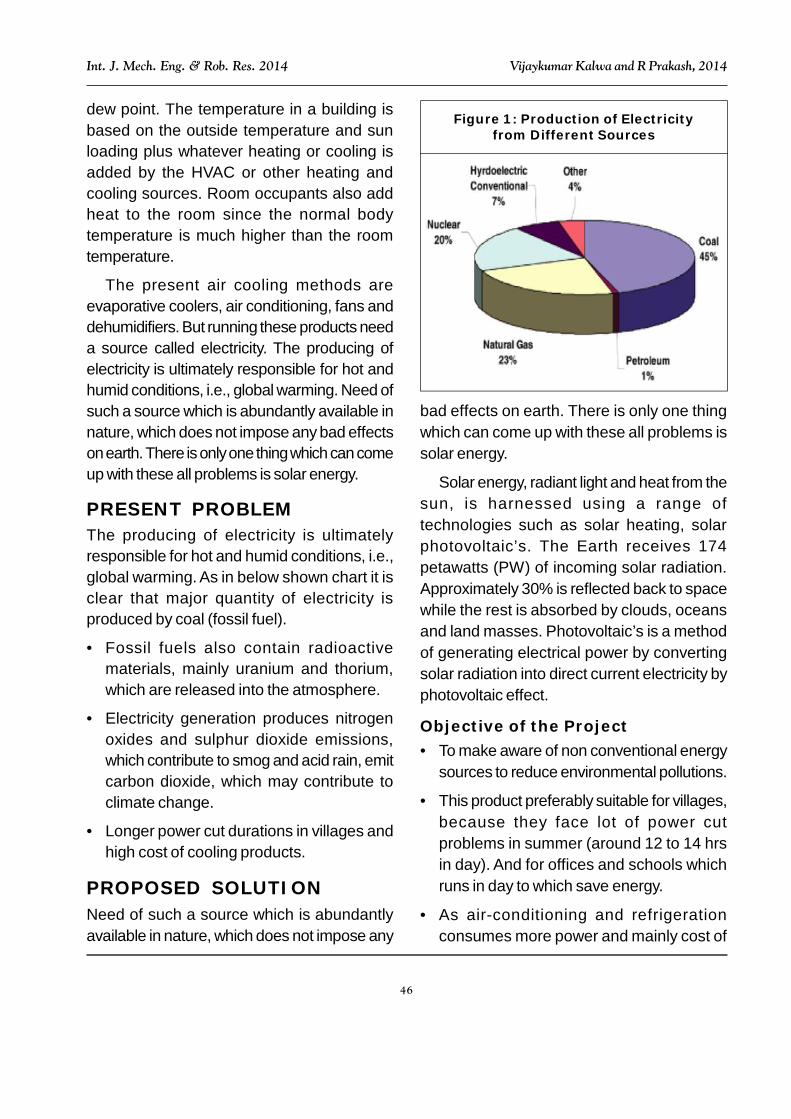
PRESENT PROBLEMThe producing of electricity is ultimatelyresponsible for hot and humid conditions, i.e.,global warming. As in below shown chart it isclear that major quantity of electricity isproduced by coal (fossil fuel).
• Fossil fuels also contain radioactivematerials, mainly uranium and thorium,which are released into the atmosphere.
• Electricity generation produces nitrogenoxides and sulphur dioxide emissions,which contribute to smog and acid rain, emitcarbon dioxide, which may contribute toclimate change.
• Longer power cut durations in villages andhigh cost of cooling products.
PROPOSED SOLUTIONNeed of such a source which is abundantlyavailable in nature, which does not impose any
bad effects on earth. There is only one thingwhich can come up with these all problems issolar energy.
Solar energy, radiant light and heat from thesun, is harnessed using a range oftechnologies such as solar heating, solarphotovoltaic’s. The Earth receives 174petawatts (PW) of incoming solar radiation.Approximately 30% is reflected back to spacewhile the rest is absorbed by clouds, oceansand land masses. Photovoltaic’s is a methodof generating electrical power by convertingsolar radiation into direct current electricity byphotovoltaic effect.
Objective of the Project• To make aware of non conventional energy
sources to reduce environmental pollutions.
• This product preferably suitable for villages,because they face lot of power cutproblems in summer (around 12 to 14 hrsin day). And for offices and schools whichruns in day to which save energy.
• As air-conditioning and refrigerationconsumes more power and mainly cost of
Figure 1: Production of Electricityfrom Different Sources
47
Int. J. Mech. Eng. & Rob. Res. 2014 Vijaykumar Kalwa and R Prakash, 2014
refrigerating and air conditioning productsare very high. So would like develop productwhich runs by solar energy and providecooling effect for house hold food items atlower cost.
WORKING METHODOLOGYThis project mainly consist of three sections,
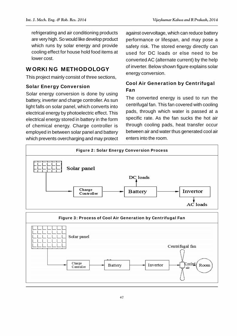
Solar Energy ConversionSolar energy conversion is done by usingbattery, inverter and charge controller. As sunlight falls on solar panel, which converts intoelectrical energy by photoelectric effect. Thiselectrical energy stored in battery in the formof chemical energy. Charge controller isemployed in between solar panel and batterywhich prevents overcharging and may protect
against overvoltage, which can reduce batteryperformance or lifespan, and may pose asafety risk. The stored energy directly canused for DC loads or else need to beconverted AC (alternate current) by the helpof inverter. Below shown figure explains solarenergy conversion.
Cool Air Generation by CentrifugalFanThe converted energy is used to run thecentrifugal fan. This fan covered with coolingpads, through which water is passed at aspecific rate. As the fan sucks the hot airthrough cooling pads, heat transfer occurbetween air and water thus generated cool airenters into the room.
Figure 2: Solar Energy Conversion Process
Figure 3: Process of Cool Air Generation by Centrifugal Fan
48
Int. J. Mech. Eng. & Rob. Res. 2014 Vijaykumar Kalwa and R Prakash, 2014
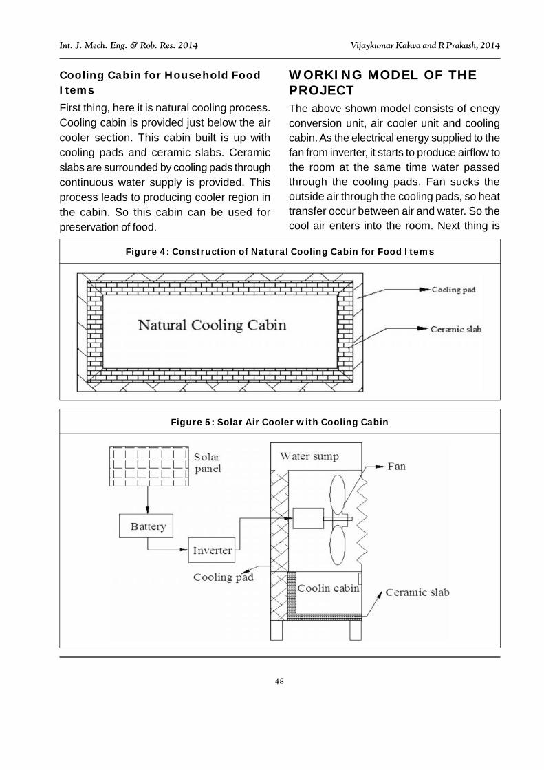
Cooling Cabin for Household FoodItemsFirst thing, here it is natural cooling process.Cooling cabin is provided just below the aircooler section. This cabin built is up withcooling pads and ceramic slabs. Ceramicslabs are surrounded by cooling pads throughcontinuous water supply is provided. Thisprocess leads to producing cooler region inthe cabin. So this cabin can be used forpreservation of food.
WORKING MODEL OF THEPROJECTThe above shown model consists of enegyconversion unit, air cooler unit and coolingcabin. As the electrical energy supplied to thefan from inverter, it starts to produce airflow tothe room at the same time water passedthrough the cooling pads. Fan sucks theoutside air through the cooling pads, so heattransfer occur between air and water. So thecool air enters into the room. Next thing is
Figure 4: Construction of Natural Cooling Cabin for Food Items
Figure 5: Solar Air Cooler with Cooling Cabin
49
Int. J. Mech. Eng. & Rob. Res. 2014 Vijaykumar Kalwa and R Prakash, 2014
cooling cabin provided just below the air coolersection. This cabin built is up with cooling padsand ceramic slabs. Ceramic slabs aresurrounded by cooling pads throughcontinuous water supply is provided. Thisprocess leads to producing cooler environmentin the cabin. So this cabin can be used forpreservation of food.
DESIGN CONSIDERATIONSOF THE PROJECTCapacity of the fan required for a particulararea can be calculated as:
Criteria: With supply of water through thecooling pads.
So, heat transfer between water and the airis given by following equation
221211
21* Twwhaha
VVTTm
sw
...(1)
where as
mw – Mass of water entering into the coolingpads per minute
V – Volume of air (m3) entering into theroom per minute (min)
Vs1 – Specific volume of air entering into thecooling room
ha1 – Enthalpy per kg of dry air at T1
ha2 – Enthalpy per kg of dry air at T2
w1 – Mass of vapour per kg of dry air at T1
w2 – Mass of vapour per kg of dry air at T2
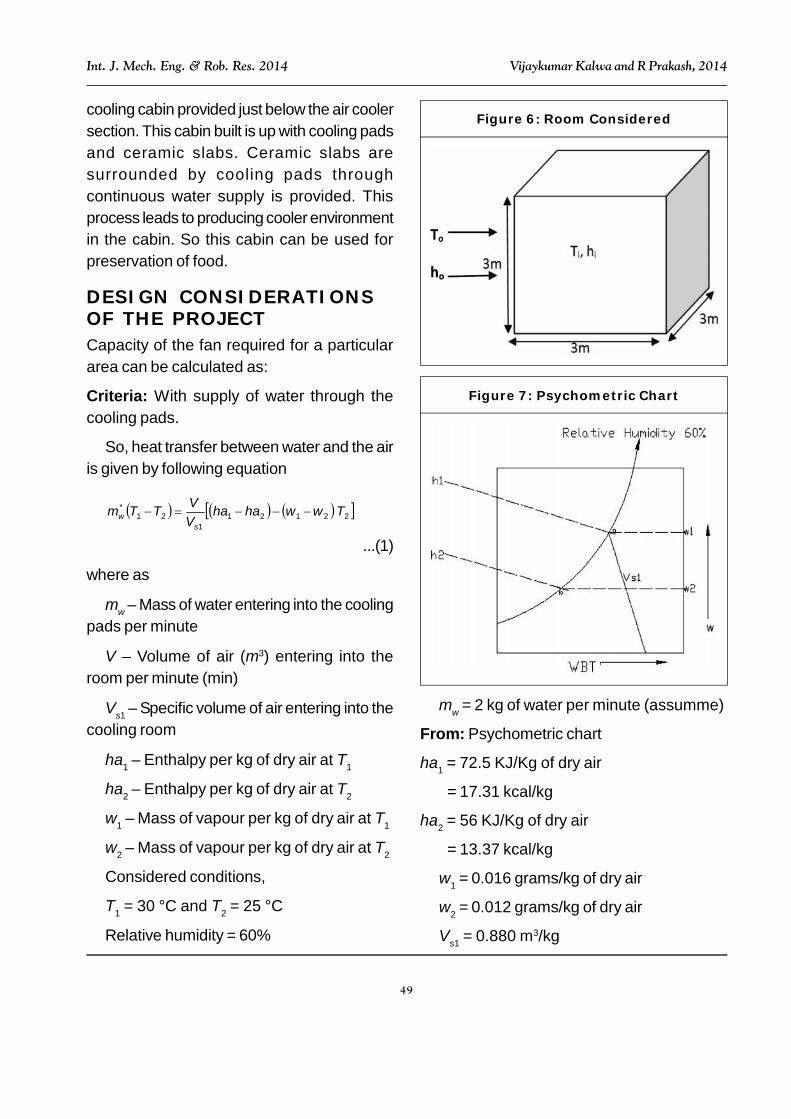
Considered conditions,
T1 = 30 °C and T2 = 25 °C
Relative humidity = 60%
Figure 6: Room Considered
mw = 2 kg of water per minute (assumme)
From: Psychometric chart
ha1 = 72.5 KJ/Kg of dry air
= 17.31 kcal/kg
ha2 = 56 KJ/Kg of dry air
= 13.37 kcal/kg
w1 = 0.016 grams/kg of dry air
w2 = 0.012 grams/kg of dry air
Vs1 = 0.880 m3/kg
Figure 7: Psychometric Chart

50
Int. J. Mech. Eng. & Rob. Res. 2014 Vijaykumar Kalwa and R Prakash, 2014
Substituting above mentioned values inEquation (1)
25*012.0016.037.1331.17880.0
2530*2 V
min/m5.2min/m291.2 33 V
So the fan capacity of 2.5 m3/min isselected.
Capacity Solar Panel and BatteryRequiredHence selected Blower (Fan) Specification:230 v, 50 Hz, 35 W
So to run 35 W blower on for 1 hour will take
35*1 = 35 Wh from the battery (Batterycapacity is measured in Amp hours)
Convert this to watt hours by multiplying theAh by the battery voltage
For 10 Ah, 12 v battery the watt hours isgiven by
P = V*I ...(2)
V = 12 v and I = 10 Ah
P = 10*12 = 120 Wh
So, the 35 W centrifugal fan runs for
120/35 = 3.42 3.5 h
This means the battery could supply 35 W
blower for213 hours.
Energy generating capacity of solar panelover a period of time:
To calculate the energy it can supply to thebattery, multiply watts by the hours exposed tosunlight, then multiply the result by 0.85 (Thisfactor allows for natural system losses).
For the solar 40 W panel in 4 hourssunshine, 40*4*0.85 = 136 Wh
For 1 hour, 40*1*0.85 = 34 Wh
So the solar panel of 40 W and battery of10 Ah are selected (Office purpose).
3D MODELLING OF THECOOLER FANModelling of the cooler fan has been done withthe help of modeling software NX 8.0, formerlyknown as NX Unigraphics, is an advancedCAD/CAM/CAE software package developedby Siemens PLM Software.
It is used among other tasks for:
• Design (parametric and direct solid/surfacemodeling).
• Manufacturing finished design by usingincluded machining modules.
Figure 8: 3D Model of the Impeller
Figure 9: 3D Model of the ImpellerInserted in Casing
51
Int. J. Mech. Eng. & Rob. Res. 2014 Vijaykumar Kalwa and R Prakash, 2014
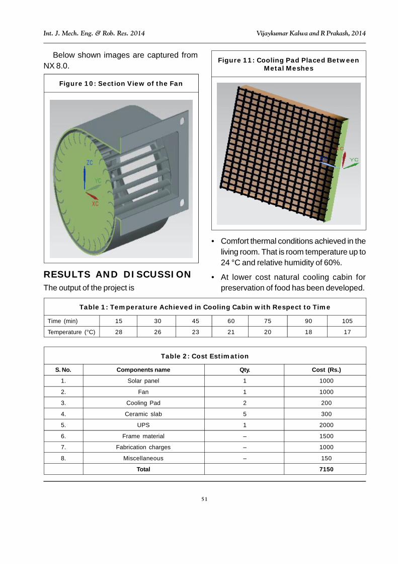
Below shown images are captured fromNX 8.0.
Figure 10: Section View of the Fan
Figure 11: Cooling Pad Placed BetweenMetal Meshes
RESULTS AND DISCUSSIONThe output of the project is
• Comfort thermal conditions achieved in theliving room. That is room temperature up to24 °C and relative humidity of 60%.
• At lower cost natural cooling cabin forpreservation of food has been developed.
Time (min) 15 30 45 60 75 90 105
Temperature (°C) 28 26 23 21 20 18 17
Table 1: Temperature Achieved in Cooling Cabin with Respect to Time
S. No. Components name Qty. Cost (Rs.)
1. Solar panel 1 1000
2. Fan 1 1000
3. Cooling Pad 2 200
4. Ceramic slab 5 300
5. UPS 1 2000
6. Frame material – 1500
7. Fabrication charges – 1000
8. Miscellaneous – 150
Total 7150
Table 2: Cost Estimation

52
Int. J. Mech. Eng. & Rob. Res. 2014 Vijaykumar Kalwa and R Prakash, 2014
CONCLUSIONSo as comparing the cost of this product withthe existing products in the market is, solarproduct appeals better and affordable bycommon people. This solar product perfectlysuits for villages, schools and offices and thusprevention from the power cut problems. Itcomprises of many attractive features such asusage of solar energy, cooler and cooling cabinat lower cost. The above method is eco friendlyand natural, electricity savers.
Durability of our product is more thusminimizing the cost. No electricity is spent sothis product saves the energy and savesenvironment from getting polluted.
REFERENCES1. Alosaimy A S (2013), “Application of
Evaporative Air Coolers Coupled withSolar Water Heater for Dehumidification
of Indoor Air”, International Journal ofMechanical & MechatronicsEngineering, Vol. 13, No. 01, pp. 60-68.
2. Arora S C and Domkundwar S (1988), “ACourse in Power Plant Engineering”, AText Book.
3. Farhan Khmamas (2012), “Improvingthe Environmental Cooling for Air-Coolers by Using the Indirect-CoolingMethod”, ARPN Journal of Engineeringand Applied Sciences, Vol. 5, No. 2,pp. 66-73.
4. SERI (1982), “Basic PhotovoltaicPrinciples and Methods”, SERI/SP-290-1448, Solar Information Module 6213.
5. Srinivas Reddy B and HemachandraReddy K (2007), “Thermal EngineeringData Hand Book”, I K InternationalPublishing House.