modelling and verification of relay interlocking systems€¦ · modelling and veri cation of relay...
TRANSCRIPT

Modelling and Verification of RelayInterlocking Systems
Morten AanæsHoang Phuong Thai
Kongens Lyngby 2012IMM-MSC-2012-14

Technical University of DenmarkInformatics and Mathematical ModellingBuilding 321, DK-2800 Kongens Lyngby, DenmarkPhone +45 45253351, Fax +45 [email protected]
Summary
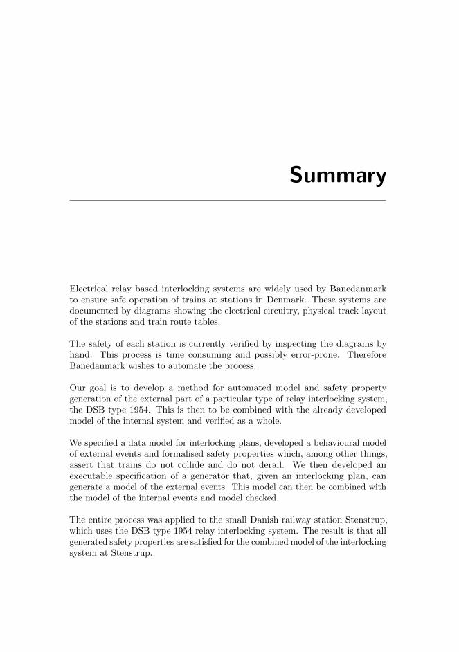
Electrical relay based interlocking systems are widely used by Banedanmarkto ensure safe operation of trains at stations in Denmark. These systems aredocumented by diagrams showing the electrical circuitry, physical track layoutof the stations and train route tables.
The safety of each station is currently verified by inspecting the diagrams byhand. This process is time consuming and possibly error-prone. ThereforeBanedanmark wishes to automate the process.
Our goal is to develop a method for automated model and safety propertygeneration of the external part of a particular type of relay interlocking system,the DSB type 1954. This is then to be combined with the already developedmodel of the internal system and verified as a whole.
We specified a data model for interlocking plans, developed a behavioural modelof external events and formalised safety properties which, among other things,assert that trains do not collide and do not derail. We then developed anexecutable specification of a generator that, given an interlocking plan, cangenerate a model of the external events. This model can then be combined withthe model of the internal events and model checked.
The entire process was applied to the small Danish railway station Stenstrup,which uses the DSB type 1954 relay interlocking system. The result is that allgenerated safety properties are satisfied for the combined model of the interlockingsystem at Stenstrup.

ii
Resume
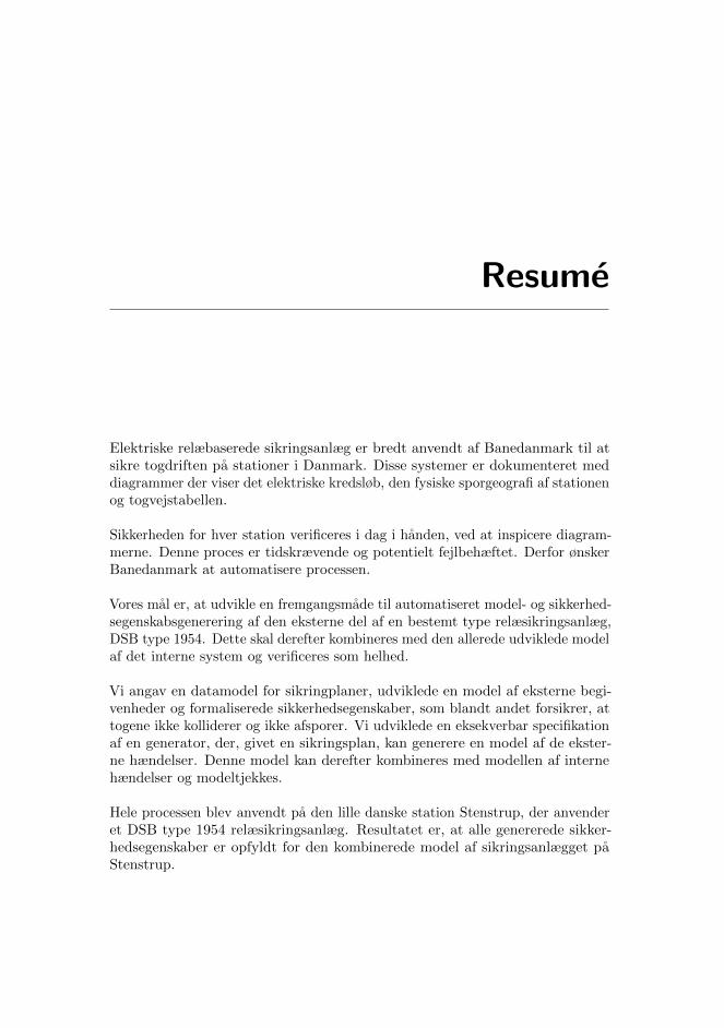
Elektriske relæbaserede sikringsanlæg er bredt anvendt af Banedanmark til atsikre togdriften pa stationer i Danmark. Disse systemer er dokumenteret meddiagrammer der viser det elektriske kredsløb, den fysiske sporgeografi af stationenog togvejstabellen.
Sikkerheden for hver station verificeres i dag i handen, ved at inspicere diagram-merne. Denne proces er tidskrævende og potentielt fejlbehæftet. Derfor ønskerBanedanmark at automatisere processen.
Vores mal er, at udvikle en fremgangsmade til automatiseret model- og sikkerhed-segenskabsgenerering af den eksterne del af en bestemt type relæsikringsanlæg,DSB type 1954. Dette skal derefter kombineres med den allerede udviklede modelaf det interne system og verificeres som helhed.
Vi angav en datamodel for sikringplaner, udviklede en model af eksterne begi-venheder og formaliserede sikkerhedsegenskaber, som blandt andet forsikrer, attogene ikke kolliderer og ikke afsporer. Vi udviklede en eksekverbar specifikationaf en generator, der, givet en sikringsplan, kan generere en model af de ekster-ne hændelser. Denne model kan derefter kombineres med modellen af internehændelser og modeltjekkes.
Hele processen blev anvendt pa den lille danske station Stenstrup, der anvenderet DSB type 1954 relæsikringsanlæg. Resultatet er, at alle genererede sikker-hedsegenskaber er opfyldt for den kombinerede model af sikringsanlægget paStenstrup.

iv

Preface
This master’s thesis was prepared at the Department of Informatics and Math-ematical Modelling (IMM) at the Technical University of Denmark (DTU) inpartial fulfilment of the requirements for acquiring the M.Sc. degree in ComputerScience and Engineering.
The work was carried out in the period September 5th 2011 to February 29th
2012 and is worth 30 ECTS points. The project was supervised by AssociateProfessor Anne Elisabeth Haxthausen, DTU IMM and co-supervised by KirstenMark Hansen, Banedanmark.
The thesis deals with automating the verification process of relay based inter-locking systems, in particular the generation of behavioural models from staticdiagrams and safety property generation.
The authors claim equal responsibility of the thesis.
Kgs. Lyngby, February 2012
Morten AanæsHoang Phuong Thai

vi
Versions
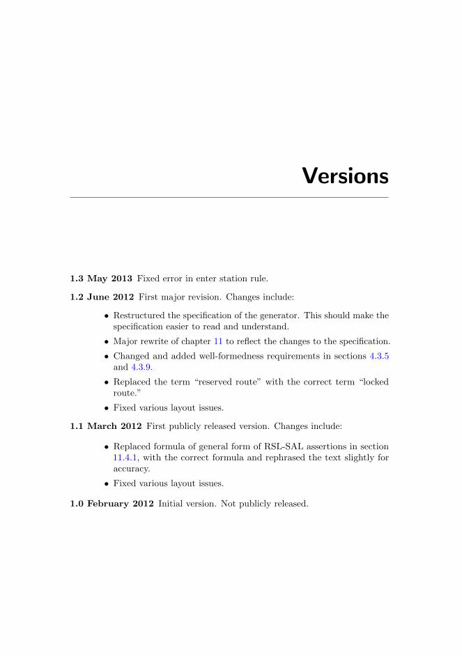
1.3 May 2013 Fixed error in enter station rule.
1.2 June 2012 First major revision. Changes include:
• Restructured the specification of the generator. This should make thespecification easier to read and understand.
• Major rewrite of chapter 11 to reflect the changes to the specification.
• Changed and added well-formedness requirements in sections 4.3.5and 4.3.9.
• Replaced the term “reserved route” with the correct term “lockedroute.”
• Fixed various layout issues.
1.1 March 2012 First publicly released version. Changes include:
• Replaced formula of general form of RSL-SAL assertions in section11.4.1, with the correct formula and rephrased the text slightly foraccuracy.
• Fixed various layout issues.
1.0 February 2012 Initial version. Not publicly released.

viii

Acknowledgements
We would like to thank
Anne E. Haxthausen for showing great interest in the project and spendinga lot of time discussing the project with us. We really appreciate it.
Alex Landex for allowing us to attend parts of the course Signalling Systemsfor Railways at DTU.
Kirsten M. Hansen for taking time out of her busy schedule to answer somequestions of ours.
Kasper B. Nielsen for providing feedback on the thesis.
And our other close friends for their feedback.

x
Contents
Summary i
Resume iii
Preface v
Versions vii
Acknowledgements ix
1 Introduction 1
1.1 Motivation . . . . . . . . . . . . . . . . . . . . . . . . . . . . . . 2
1.2 Related Work . . . . . . . . . . . . . . . . . . . . . . . . . . . . . 3
1.3 Goal . . . . . . . . . . . . . . . . . . . . . . . . . . . . . . . . . . 5
1.4 Prerequisites . . . . . . . . . . . . . . . . . . . . . . . . . . . . . 6
1.5 Chapter Overview . . . . . . . . . . . . . . . . . . . . . . . . . . 6
2 Domain Description 9
2.1 Railway Network . . . . . . . . . . . . . . . . . . . . . . . . . . . 10
2.2 Trains . . . . . . . . . . . . . . . . . . . . . . . . . . . . . . . . . 13
2.3 Signalling . . . . . . . . . . . . . . . . . . . . . . . . . . . . . . . 14
2.4 Safety . . . . . . . . . . . . . . . . . . . . . . . . . . . . . . . . . 15
2.5 Interlocking System . . . . . . . . . . . . . . . . . . . . . . . . . 19
2.6 Interlocking Plan . . . . . . . . . . . . . . . . . . . . . . . . . . . 24
3 Method Description 33
3.1 Approach . . . . . . . . . . . . . . . . . . . . . . . . . . . . . . . 33
3.2 Suggested Method . . . . . . . . . . . . . . . . . . . . . . . . . . 34

xii CONTENTS
4 Data Models 37
4.1 Interlocking Plan . . . . . . . . . . . . . . . . . . . . . . . . . . . 37
4.2 Station Layout Diagram . . . . . . . . . . . . . . . . . . . . . . . 38
4.3 Train Route Table . . . . . . . . . . . . . . . . . . . . . . . . . . 52
4.4 Transition System . . . . . . . . . . . . . . . . . . . . . . . . . . 71
5 Behavioural Model of the Internal System 81
5.1 State Space . . . . . . . . . . . . . . . . . . . . . . . . . . . . . . 82
5.2 Transition Rules . . . . . . . . . . . . . . . . . . . . . . . . . . . 84
5.3 The Timing Issue . . . . . . . . . . . . . . . . . . . . . . . . . . . 84
6 Behavioural Model of Train Movements 87
6.1 Approaches to Modelling Train Movement . . . . . . . . . . . . . 87
6.2 Model of Trains . . . . . . . . . . . . . . . . . . . . . . . . . . . . 89
6.3 Model of Train Movements . . . . . . . . . . . . . . . . . . . . . 93
6.4 Rubber Band Trains . . . . . . . . . . . . . . . . . . . . . . . . . 106
7 Behavioural Model of Buttons and Points 109
7.1 Button Behaviour . . . . . . . . . . . . . . . . . . . . . . . . . . . 109
7.2 Points Behaviour . . . . . . . . . . . . . . . . . . . . . . . . . . . 110
8 Associations 115
8.1 Object Relay Associations . . . . . . . . . . . . . . . . . . . . . . 116
8.2 Train Movement Associations . . . . . . . . . . . . . . . . . . . . 120
9 Inter-Model Consistency 129
9.1 Variables . . . . . . . . . . . . . . . . . . . . . . . . . . . . . . . 130
9.2 Track Occupation . . . . . . . . . . . . . . . . . . . . . . . . . . . 131
9.3 Track Free . . . . . . . . . . . . . . . . . . . . . . . . . . . . . . . 131
9.4 Train Direction . . . . . . . . . . . . . . . . . . . . . . . . . . . . 132
9.5 Points Configuration . . . . . . . . . . . . . . . . . . . . . . . . . 133
9.6 Train Connection . . . . . . . . . . . . . . . . . . . . . . . . . . . 134
10 Safety Properties 135
10.1 Variables . . . . . . . . . . . . . . . . . . . . . . . . . . . . . . . 135
10.2 No Collision . . . . . . . . . . . . . . . . . . . . . . . . . . . . . . 137
10.3 No Derailing . . . . . . . . . . . . . . . . . . . . . . . . . . . . . 137
10.4 Points Position . . . . . . . . . . . . . . . . . . . . . . . . . . . . 139
10.5 Signal . . . . . . . . . . . . . . . . . . . . . . . . . . . . . . . . . 139
10.6 Signal Release . . . . . . . . . . . . . . . . . . . . . . . . . . . . . 141
10.7 Conflicting Routes . . . . . . . . . . . . . . . . . . . . . . . . . . 141
10.8 Train Route Release . . . . . . . . . . . . . . . . . . . . . . . . . 142

CONTENTS xiii
11 Generator 14511.1 Overview . . . . . . . . . . . . . . . . . . . . . . . . . . . . . . . 14611.2 State Generator . . . . . . . . . . . . . . . . . . . . . . . . . . . . 14711.3 Transition Generator . . . . . . . . . . . . . . . . . . . . . . . . . 15511.4 Assertion Generator . . . . . . . . . . . . . . . . . . . . . . . . . 16711.5 Output . . . . . . . . . . . . . . . . . . . . . . . . . . . . . . . . 175
12 Test 18112.1 Station Layout . . . . . . . . . . . . . . . . . . . . . . . . . . . . 18112.2 Results . . . . . . . . . . . . . . . . . . . . . . . . . . . . . . . . . 182
13 Case Study - Stenstrup 18713.1 Defining Stenstrup . . . . . . . . . . . . . . . . . . . . . . . . . . 18713.2 Generating Model of External Events . . . . . . . . . . . . . . . . 19313.3 Combining the Models . . . . . . . . . . . . . . . . . . . . . . . . 19613.4 Results Stenstrup . . . . . . . . . . . . . . . . . . . . . . . . . . . 197
14 Conclusion 19914.1 Future Work . . . . . . . . . . . . . . . . . . . . . . . . . . . . . 201
A Word List 205
B Documentation of Stenstrup Station 207
C User Guide 211C.1 Requirements . . . . . . . . . . . . . . . . . . . . . . . . . . . . . 211C.2 Stenstrup . . . . . . . . . . . . . . . . . . . . . . . . . . . . . . . 212
D Behavioural Model of Train Movements Using Explicitly DefinedTrains 215D.1 Enter . . . . . . . . . . . . . . . . . . . . . . . . . . . . . . . . . 216D.2 Leave . . . . . . . . . . . . . . . . . . . . . . . . . . . . . . . . . 218
E Specifications 221E.1 Data Models . . . . . . . . . . . . . . . . . . . . . . . . . . . . . 221E.2 Generators . . . . . . . . . . . . . . . . . . . . . . . . . . . . . . 238E.3 Associations . . . . . . . . . . . . . . . . . . . . . . . . . . . . . . 273E.4 Misc. . . . . . . . . . . . . . . . . . . . . . . . . . . . . . . . . . . 280E.5 Test . . . . . . . . . . . . . . . . . . . . . . . . . . . . . . . . . . 290
F Output 333F.1 Output of Generator . . . . . . . . . . . . . . . . . . . . . . . . . 333F.2 Output of Model Checker . . . . . . . . . . . . . . . . . . . . . . 347F.3 Output of Tests . . . . . . . . . . . . . . . . . . . . . . . . . . . . 356

xiv CONTENTS

Chapter 1
Introduction
This chapter gives an introduction to the overarching problem we seek to solve,present the related work and precisely define what we are trying to achieve.
Section 1.1 will introduce and justify the problem we are trying to solve.
Section 1.2 will explain what has been done before and what to choose to buildupon and what we wish to improve.
Section 1.3 will explain the problem in greater detail, followed by a brief sketchof how we plan to solve it.
Section 1.4 will state some assumptions about the reader.
Lastly, section 1.5 will shortly describe each chapter in the thesis.
Throughout this chapter, terms and notions, that have not yet been explained,are used. Please refer to the domain description in chapter 2 for definitions andexplanations.
2 Introduction
1.1 Motivation
More than 170 million passengers and about 15 million tonnes of freight aretransported on Banedanmarks railway network on a yearly basis. With about40.000 train movements per day, reliability and safety are top priorities1.
The safety at the stations is ensured by interlocking systems, which control thetrack side equipment like signals, points and level crossings. Many stations onthe Danish railway are still secured by old relay based electrical interlockingsystems.
The relay based interlocking systems are documented by the station documenta-tion, which is a collection of diagrams of the layout of the track side equipment,the electrical circuitry and the train route table.
The interlocking systems are verified by manually inspecting the diagrams anddrawing conclusions about the safety. Due to the high number of diagrams andtheir mutual correlation, this process is complex, time consuming (and thusexpensive) and possibly error prone, which is not satisfactory for a safety criticalsystem.
Furthermore, the process has to be repeated whenever changes are made to thesystem, e.g. changes to the physical layout of the station or direct changes tothe relay circuits.
1.1.1 Vision
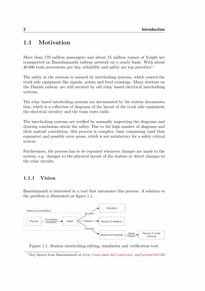
Banedanmark is interested in a tool that automates this process. A solution tothe problem is illustrated on figure 1.1.
Station Documentation
Physical DigitalTool assistedconversion
Simulation
Results of validation
Model and Properties Results of model checking
ModelChecker
Generator
Validator
Simulator
Figure 1.1: Station interlocking editing, simulation and verification tool.
1Key figures from Banedanmark at http://www.bane.dk/visArtikel.asp?artikelID=136
1.2 Related Work 3
The physical station documentation is digitalised using a graphical user interface.Here the diagrams of the circuitry and station layout are drawn and the trainroute table is created. When all the documentation is created, the system canbe simulated, so the engineer can observe how changes affect the system.
Once the engineer is satisfied with the system, the tool should then be able toautomatically verify that the system he (or she) designed, satisfies the safetyproperties required of such a system. This is done by generating a model of theinterlocking system and the safety properties.
1.2 Related Work
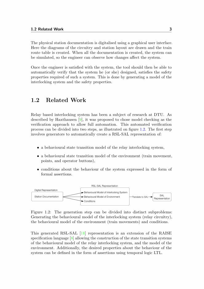
Relay based interlocking system has been a subject of research at DTU. Asdescribed by Haxthausen [9], it was proposed to chose model checking as theverification approach to allow full automation. This automated verificationprocess can be divided into two steps, as illustrated on figure 1.2. The first stepinvolves generators to automatically create a RSL-SAL representation of:
• a behavioural state transition model of the relay interlocking system,
• a behavioural state transition model of the environment (train movement,points, and operator buttons),
• conditions about the behaviour of the system expressed in the form offormal assertions.
Digital RepresentationRSL-SAL Representation
Station DocumentationBehavioural Model of Interlocking SystemBehavioural Model of EnvironmentConditions
SAL RepresentationTranslate to SAL
Figure 1.2: The generation step can be divided into distinct subproblems:Generating the behavioural model of the interlocking system (relay circuitry),the behavioural model of the environment (train movements) and conditions.
This generated RSL-SAL [11] representation is an extension of the RAISEspecification language [8] allowing the construction of the state transition systemsof the behavioural model of the relay interlocking system, and the model of theenvironment. Additionally, the desired properties about the behaviour of thesystem can be defined in the form of assertions using temporal logic LTL.

4 Introduction
The RSL-SAL representation can then, as part of the second step, be translatedto the SAL language [6] using the RAISE tool set [1], which allows the SAL modelchecker to check the validity of the two behavioural state transition systems withthe desired conditions.
In the next section (1.2.1) we will introduce the current state of the tool thathas been presented, and discuss which parts of the automatic verification processthat is complete. Also, parts of the automatic verification process is, however,not complete which will be discussed.
1.2.1 Current State of the Tool
Over time several contributors have participated to create parts of the tool tofulfil the vision stated in 1.1.1. The contributed work consists of:
Graphical Editor and Simulator : Eriksen and Pedersen [7] developed a graphicalrelay circuitry editor and simulator. It allows the system designer to reproducethe static physical circuit diagrams, and thereafter simulate the propagationof a current through the circuit, and observe as the state of the componentschange dynamically. Furthermore, they implemented an editor to create a simpleoperator’s panel as well as support for occupying and freeing track sectionsthrough the simulator. The rest of the system would then react to these events.Finally, they implemented an export feature to store the system in a XML file.
Verification Method of Relay Interlocking System: A part of the proposed toolhas been developed by Kjær and Le Bliguet [2]. Specified in RSL and imple-mented in Java, they are able to take relay diagrams in XML format as inputand automatically generate a RSL-SAL model of the internal behaviour of theinterlocking system and associated confidence conditions. Furthermore, theyhave suggested a model of the environment for Stenstrup station and safetyproperties, and shown that the system satisfies the properties they stated.
Unfortunately, there is a missing link between the two parts since the exportedXML file created by the editor is not of same format required by the verificationof the interlocking system component.
Figure 1.3 illustrates the work that has been done (in grey) and which componentsneeded to be automated.

1.3 Goal 5
RSL-SALStation Documentation
Circuit Diagrams
Station Layout
Train Route Table
Auto Generation
Manual Generation
Manual Generation
Internal BehaviourConfidence Conditions
External Behaviour
Safety Properties
Translation to SAL SAL files
SAL Model Checker
Results
Editor
Manual Generation
XML XML
Figure 1.3: Current state of the tool. Automatic generator of external behaviourand safety properties is needed.
Internal behaviour This is a model of the behaviour of the internal work-ings of the relay based interlocking system. Requiresthe circuit diagrams.
External behaviour This is a model of the behaviour of the externalevents, to which the internal part of the interlock-ing system responds. Requires the station layoutdiagram.
Safety Properties This is the conditions that is used to verify thatthe system behave as desired. Requires the stationlayout and the train route table.
1.3 Goal
Our goal is to investigate a method for automated model and safety propertygeneration of the external part of a particular type of relay interlocking system,the DSB type 1954. This is then to be combined with the already developedmodel of the internal system and verified as a whole.
This project can be seen as an extension of the work mentioned in section 1.2 andwe will therefore continue the research on the DSB type 1954 relay interlockingsystem and use Stenstrup as case study.
If successful, this would allow Banedanmark to save time on verifying andeliminate the possibility of human error.
6 Introduction
ResultsAuto Generation
Model Check
Station Documentation
Digital FormatTool Assisted
Generation
Physical Diagrams
Models and Conditions
RSL-SAL SALTranslation
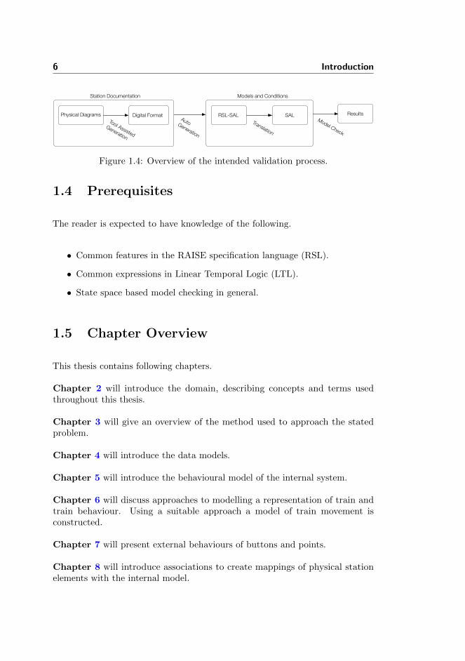
Figure 1.4: Overview of the intended validation process.
1.4 Prerequisites
The reader is expected to have knowledge of the following.
• Common features in the RAISE specification language (RSL).
• Common expressions in Linear Temporal Logic (LTL).
• State space based model checking in general.
1.5 Chapter Overview
This thesis contains following chapters.
Chapter 2 will introduce the domain, describing concepts and terms usedthroughout this thesis.
Chapter 3 will give an overview of the method used to approach the statedproblem.
Chapter 4 will introduce the data models.
Chapter 5 will introduce the behavioural model of the internal system.
Chapter 6 will discuss approaches to modelling a representation of train andtrain behaviour. Using a suitable approach a model of train movement isconstructed.
Chapter 7 will present external behaviours of buttons and points.
Chapter 8 will introduce associations to create mappings of physical stationelements with the internal model.

1.5 Chapter Overview 7
Chapter 9 will describe requirements to ensure that the interaction betweenthe model of train movement and the internal relay system behaves as expected.
Chapter 10 will present the safety properties that are requirements to thesystem to ensure safe train operation.
Chapter 11 will introduce a generator, which facilitates the generation of thetrain movements discussed in chapter 6. The generator will also introduce thegeneration of the state space and assertions.
Chapter 12 will introduce a test strategy and show a thorough test of one ofthe data models.
Chapter 13 will show a case study of Stenstrup station.
Chapter 14 will conclude the work that have been conducted. And alsopresenting future work.
Appendix A contains a word list from english to danish.
Appendix B contains documentation of Stenstrup station.
Appendix C contains a user guide of the application.
Appendex D contains a modelling approach mentioned in chapter 6.
Appendex E contains the complete specifications introduced in chapter 4 and11.

8 Introduction

Chapter 2
Domain Description
In this chapter, concepts and terms of the Danish railway domain, which isdeemed to have relevance for this project, will be introduced.
Section 2.1 gives a general description of the Danish Railways and introducesthe components it consists of.
Section 2.2 defines what a train is.
Section 2.3 introduces both the signalling equipment and the meaning of thesignals.
Section 2.4 describes the safety properties of train operation in the railway domain.Several approaches to enforcing the safety properties will also be introduced.
Section 2.5 introduces the different kinds of interlocking systems used in Denmarkand explains the relay based interlocking systems in greater detail.
Section 2.6 introduces the interlocking plan, which is part of the station docu-mentation. The diagrams shown are of Stenstrup station, which will be used ascase study throughout this thesis.

10 Domain Description
2.1 Railway Network
The Danish railway network can be divided into two distinct parts, the open line1
and stations. The stations are interconnected by the line. The line is defined asthe part of the track network, which is outside the station limits [5].
The technical definition of a railway station, used by Banedanmark is a railwaystop, which participates in the safety operation of the train service [5]. Railwaystops that does not have its own interlocking system, is secured as part of theline block interlocking system, which is a separate system from the stationinterlocking system.
In this work, only station interlocking systems are considered.
2.1.1 Track Sections
A railway network consists of rails that can be divided into sections. Thesesections are of different types, such as linears, points and level crossings.
Linear track sections are connected to either one or two other sections, whilepoints sections are able to direct traffic in one of two direction. Level crossingsare intersections between the railway and a road, but are not considered for thisproject.
Figure 2.1 describes the correlation of the track elements.
Points
Section
Linear
Figure 2.1: Definition of track sections.
1Just “line” for short.
2.1 Railway Network 11
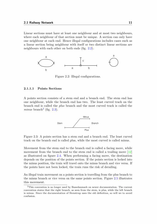
Linear sections must have at least one neighbour and at most two neighbours,where each neighbour of that section must be unique. A section can only haveone neighbour at each end. Hence illegal configurations includes cases such asa linear section being neighbour with itself or two distinct linear sections areneighbours with each other on both ends (fig. 2.2).
a
ba b
c
a
Figure 2.2: Illegal configurations.
2.1.1.1 Points Sections
A points section consists of a stem end and a branch end. The stem end hasone neighbour, while the branch end has two. The least curved track on thebranch end is called the plus branch and the most curved track is called theminus branch2 (fig. 2.3).
BranchStem
Plus
Minus
Figure 2.3: A points section has a stem end and a branch end. The least curvedtrack on the branch end is called plus, while the most curved is called minus.
Movement from the stem end to the branch end is called a facing move, whilemovement from the branch end to the stem end is called a trailing move [12]as illustrated on figure 2.4. When performing a facing move, the destinationdepends on the position of the points section. If the points section is locked intothe minus position, the train will travel onto the minus branch and vice versa. Ifthe points have not been locked, the train runs the risk of derailing.
An illegal train movement on a points section is travelling from the plus branch tothe minus branch or vice versa on the same points section. Figure 2.5 illustratesthis movement.
2This convention is no longer used by Banedanmark on newer documentation. The currentconvention states that the right branch, as seen from the stem, is plus, while the left branchis minus. Since the documentation of Stenstrup uses the old definition, so will we to avoidconfusion.
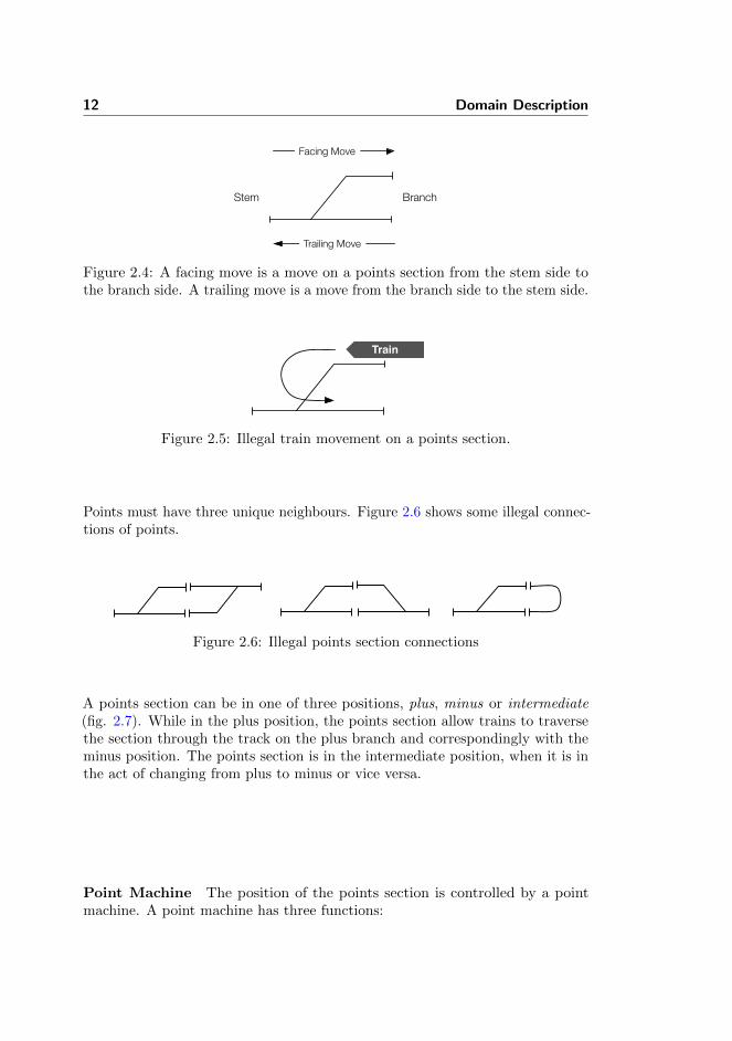
12 Domain Description
BranchStem
Facing Move
Trailing Move
Figure 2.4: A facing move is a move on a points section from the stem side tothe branch side. A trailing move is a move from the branch side to the stem side.
Train
Figure 2.5: Illegal train movement on a points section.
Points must have three unique neighbours. Figure 2.6 shows some illegal connec-tions of points.
Figure 2.6: Illegal points section connections
A points section can be in one of three positions, plus, minus or intermediate(fig. 2.7). While in the plus position, the points section allow trains to traversethe section through the track on the plus branch and correspondingly with theminus position. The points section is in the intermediate position, when it is inthe act of changing from plus to minus or vice versa.
Point Machine The position of the points section is controlled by a pointmachine. A point machine has three functions:

2.2 Trains 13
Plus
Intermediate
Minus
Figure 2.7: The different states of a points section. When in the plus position, itallows movements by the plus branch and likewise with the minus position. Thepoints section is in the intermediate position when it is not locked in either plusor minus.
Switching points The point machine is responsible for physicallyswitching the points.
Locking points The point machine is responsible for physically lock-ing the points, once they are in position.
Supervising points The point machine must communicate the statusof the points, i.e. the position of the points andwhether they are locked or not.
2.2 Trains
The technical definition of a train is rolling stock that performs a train movement,i.e. travels from one station to another3 [10]. Rolling stock is any vehicle thatdrives on a railway, which corresponds to the everyday notion of a train.
Trains have a long braking distance due to the low friction between wheel andrail. Combined with the weight of a freight train or the speed of a passenger train,trains often cannot stop within the sighting distance of the driver. Thereforerailway operations rely on interlocking systems to ensure that the track withinbraking distance in front of the train is clear.
A shunting movement, on the other hand, is movement of rolling stock withinthe limits of a station. Due to the nature of shunting movements, other (lessrestrictive) safety rules apply to shunting movements.
3The definition of a train varies slightly around the world.
14 Domain Description
2.3 Signalling
Signalling is a method of communication used in the railway domain to indicatethe state of the track ahead. The method of signalling varies from country tocountry, but the main objective is to notify the train driver whether to stop orproceed.
Regardless of the method of signalling (see section 2.3.2), a signal is a way ofcommunicating a certain indication.
2.3.1 Indication
An indication is the meaning of a signal. Different signals can have the same in-dication. The following describes certain indications, which are used in Denmarkand relevant for this project.
Stop The train may not proceed past the signal.
Stop and proceed The train must stop at the signal and may then care-fully proceed past the signal to the next signal.
Proceed The train may proceed past the signal and prepareto stop at the next signal.
Proceed through The train may proceed past the signal and the next,which will show proceed or proceed through.
2.3.2 Signals
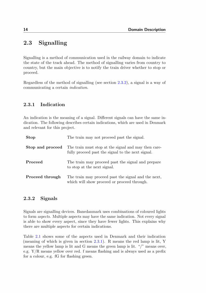
Signals are signalling devices. Banedanmark uses combinations of coloured lightsto form aspects. Multiple aspects may have the same indication. Not every signalis able to show every aspect, since they have fewer lights. This explains whythere are multiple aspects for certain indications.
Table 2.1 shows some of the aspects used in Denmark and their indication(meaning of which is given in section 2.3.1). R means the red lamp is lit, Ymeans the yellow lamp is lit and G means the green lamp is lit. “/” means over,e.g. Y/R means yellow over red. f means flashing and is always used as a prefixfor a colour, e.g. fG for flashing green.
2.4 Safety 15
Aspect Indication
R Y/R Stop
fR Y/fR Stop and proceed
Y/G Proceed (at limited speed)
G Proceed
fG G/G Proceed through
Table 2.1: Aspects of main signals and their indication
In this work, we are only interested in stopping and moving trains, ignoring speedlimitations. Disregarding the signalling variants of stopping and proceeding theaspects has been reduced to the stop and proceed aspects. Table 2.2 denotes theaspects used throughout this thesis.
Aspect Indication
R StopG Proceed
Table 2.2: Aspects
2.4 Safety
In this section the safety properties of the railway network are described aswell as how it is enforced to ensure the safety of passengers and trains. Theseproperties is a set of requirements to the system that needs to be maintainedat all time. Furthermore, safety approaches are introduced, which are differentkinds of implementations to maintain these safety properties.

16 Domain Description
2.4.1 Safety Properties
In the previous sections we have introduced the elements to construct a workingrailway network. The interaction between all these objects constitute the safetyof the train operations. These interactions needs to follow a set of rules to fulfilthe basic safety requirements, namely [4]:
• Trains/shunt movements must not collide.
• Trains/shunt movements must not derail.
• Train/shunt movements must not collide with vehicles or humans crossingthe railway at authorised crossings.
• Protect railway employees from trains.
For this thesis we do not consider shunting movements, level crossings andrailway employees. Therefore the basic safety requirements can be reduced tothe following subset of the basic safety requirements:
• Trains must not collide.
• Trains must not derail.
Henceforth, any reference to the basic safety requirements will be to the abovesubset.
In the following sections it will be explained how the events of collision andderailing can occur, and later how to avoid them.
2.4.1.1 Collision
A collision is an unintended contact between trains. Combining trains is anexample of intended contact between trains. High speed collisions, on the otherhand, are likely to have catastrophic consequences.
We consider any situation where two or more trains occupy the same tracksection a collision. This situation will not necessarily result in a collision, butthe potential is there and that is enough for it to be considered a collision.
2.4 Safety 17
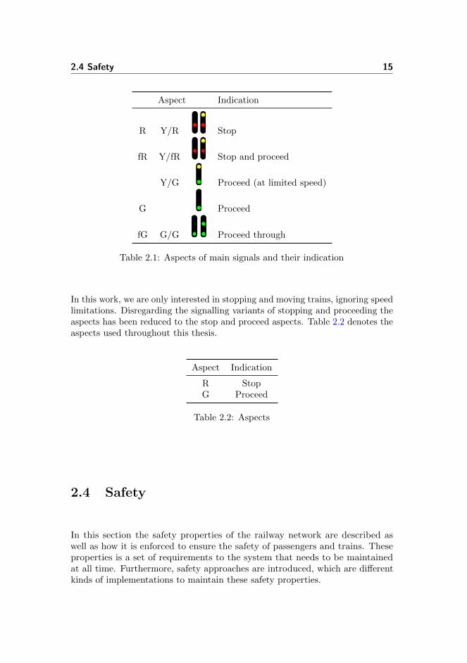
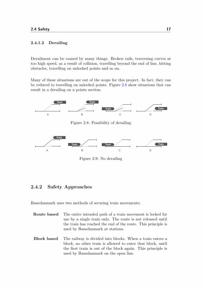
2.4.1.2 Derailing
Derailment can be caused by many things. Broken rails, traversing curves attoo high speed, as a result of collision, travelling beyond the end of line, hittingobstacles, travelling on unlocked points and so on.
Many of these situations are out of the scope for this project. In fact, they canbe reduced to travelling on unlocked points. Figure 2.8 show situations that canresult in a derailing on a points section.
Train
Train
Train
Train
A B C D
Figure 2.8: Possibility of derailing
Train
Train TrainTrain
A B C D
Figure 2.9: No derailing
2.4.2 Safety Approaches
Banedanmark uses two methods of securing train movements:
Route based The entire intended path of a train movement is locked foruse by a single train only. The route is not released untilthe train has reached the end of the route. This principle isused by Banedanmark at stations.
Block based The railway is divided into blocks. When a train enters ablock, no other train is allowed to enter that block, untilthe first train is out of the block again. This principle isused by Banedanmark on the open line.

18 Domain Description
2.4.2.1 Train Route
A train route is a secured path from one point4 (called the start point) toanother (called the end point) in a railway network. These points are normallysignals [10].
The following describes the concepts associated with train routes.
Safety overlap The safety overlap is an extension of a train route, intendedto provide additional clear track in case the train fails to stop at the end point,e.g. the driver misjudges the braking distance.
Conflicting train routes Train routes are considered conflicting if they sharepoints in their paths, incl. the safety overlap. Conflicting train routes aremutually exclusive and may not be locked at the same time. However, it ispossible to extend a route with another by replacing the safety overlap withanother route.
Flank protection Flank protection is protecting a train route from conflictingmovements. The interlocking system achieves this first and foremost, by notallowing conflicting routes. This protects against train movements, but notagainst roll away vehicles. Therefore, further measures are taken, such as lockingpoints, that are not part of the route, into positions that direct traffic away fromthe route in question
Locking train route A train route can be locked manually by pressing buttonson the operator’s panel or automatically when the system detects an approachingtrain.
A train route can be locked if the track sections, that constitutes the route, areall clear, the points sections on the route are locked in proper position and thedesired route is not in conflict with any other currently locked route.
A train route stays locked until it is released. The objects, which were part ofthe released train route, can then be used to form new train routes.
4This does not refer to points sections.

2.5 Interlocking System 19
Release of train route A train route can be released in one of two ways,either automatically or manually.
Automatic release is performed by the interlocking system and happens once atrain has completed its train movement.
Manual release is performed from the operator’s panel. It can be performedeven if a train is already on the route, but then the train no longer has the samemeasure of protection. Manual release of train routes is not considered.
2.5 Interlocking System
An interlocking system is a mechanical, electrical, electronic or hybrid systemthat controls physical objects, such as signals and points, in a limited area [10].
The Danish railway network is controlled by several different generations ofinterlocking systems, ranging from the very old mechanical, over the electricalrelay based systems of the ’50s and ’60s to the newer computer based electronicsystems.
This work considers the 54 type relay based interlocking system, since this is thetype that is used at Stenstrup.
The interlocking system has three major fundamental tasks, which is to control,supervise and ensure safety.
Control Manuel or automatic operation of points, signals etc.
Supervision Continual supervision of the state of points, signals,isolation etc.
Ensuring Safety Preventing points, signals etc. to be operated in such away that it allows conflicting train movements.
2.5.1 Relay Based Interlocking
In a relay based interlocking system, the rules of the interlocking system isimplemented in electrical circuits. A circuit consists of components, such as

20 Domain Description
relays, contacts and buttons, that are connected by wires and powered by apower supply.
2.5.1.1 Relays
A relay is an electrical component that can be in two states, drawn (symbolisedwith ↑) and dropped (↓).
When power is supplied, the relay will be energised. This activates the electro-magnet, which draws the armature so that the upper contacts become connectedwhile the lower become disconnected (fig. 2.10a).
When the power is cut, the magnetic field will disappear and gravity will causethe armature to drop. This again switches the active connections (fig. 2.10b).
Elec
tromag
net
+-
Armature
Contacts
(a) Relay drawn
+-
(b) Relay dropped
Figure 2.10: When a current energises a relay, its electromagnet is activated.This pulls the armature, which creates a connection with the upper contacts (a).Without power, the armature is dropped, which creates a connection with thelower contacts instead (b).
Other types of relays exists, for example steel core relays, which are able toretain their state even after losing power.
2.5.1.2 Logic of Relay Based Interlocking Systems
The state of the physical objects can be captured by relays. By assigning a relay(and sometimes multiple replays) to each physical object on the station, the

2.5 Interlocking System 21
state of the entire station is captured. This can then be use to control the trainmovements in a safe manner.
Each track section has a relay associated (called a track relay), which is drawnwhen the track is considered vacant.
Each points section has two additional relays associated. One is drawn whenthe points section is locked in the plus position and the other is drawn when thepoints section is locked in the minus position.
In addition there are relays capturing the state of route locking, route releasing,each lamp on each signal etc.
Buttons can be pushed and released. When a button is pushed, the current isallowed to flow through, while the connection is cut when the button is released.
A relay based interlocking system consists of two parts, the internal system andthe external system. The internal system is the relay circuitry that is controlledby the interlocking system, e.g. the signal relays. The external system on theother hand, consists of the circuitry that is controlled by the environment, e.g.points relays, and train detection relays.
The logic of the system is created by arranging the connections of the componentsin a certain way. Serial connections create conjunctions, while parallel connectionscreate disjunctions, as the current will follow whichever path it is allowed (fig.2.11).
The situation on fig. 2.11a can be translated to the following boolean expressionL = A ∧B, where L is true when the lamp is turned on and A and B are truewhen the respective button is pressed. Similarly the situation on fig. 2.11b canbe translated to L = A ∨B, meaning either button A or B must be pressed forthe lamp to turn on.
Circuit Diagrams The circuit system is documented in circuit diagrams aspart of the station documentation. The diagrams are divided by functionality,such that one diagram may show the route locking, while another shows theroute release. The diagrams always shows the system in the normal state. Thenormal state is the state the system is in when every track section is vacant, notrain routes are locked, the points are in their initial position and so on.
The system is operated from the operator’s panel.

22 Domain Description
A
B
L
(a) Conjunction
A B
L
(b) Disjunction
Figure 2.11: Serial connecting components create a conjunctive relationshipbetween them, as seen in (a) where buttons A and B are serial connected tothe lamp L. When both buttons are pressed, the current will be able to passthrough and turn on the lamp. (b) shows a situation where buttons A and Bare connected in parallel to the lamp L. The lamp will turn on if either A or Bis pressed.
2.5.1.3 Operator’s Panel
The operator’s panel shows the layout of the station and is equipped with buttonsand lamps. Some buttons are used to switch the position of the points, some areused to lock routes (fig. 2.12), while others again have different purposes. Thelamps indicate the state of track sections and points.
Figure 2.12: Diagram of operator’s panel for Stenstrup station.
Switching Points The position of a points section is switched by pressing andholding the + or − button next to the points section. When the position has been

2.5 Interlocking System 23
locked in either the plus or minus position a lamp will lit on the correspondingbranch.
Locking Routes A route is locked by holding the button for the start pointand the end point. The buttons are marked I, U and T. Button I is used toindicate the start of an entry route, while button U is used to indicate the startof an exit route. U or I must be pressed in combination with a T button, whichindicates the end of the route.
2.5.2 Train Detection Equipment
Different methods of track detection are adopted throughout the world. Bane-danmark uses track circuits.
2.5.2.1 Track Circuit
A track circuit is a device that detects the absence of trains.
Each rail is connected to a power supply in one end and a relay in the other end.Since the rails are conductive, the relay will be energised by the current runningthrough the rails (fig. 2.13a). Since train wheels and axles are conductive as well,a train on the track section will cause a short circuit, thus cutting the power tothe relay. Without power, gravity will cause the relay to drop (fig. 2.13b).
+-
Current Flow
(a) Relay drawn
+-
(b) Relay dropped
Figure 2.13: As long as the track section is clear, the current can travel throughthe rails and energise the relay (a). A train on tracks, on the other hand, willcause a short circuit, preventing power to reach the relay, which will drop (b).

24 Domain Description
As a consequence of this design, the relay will drop in case of power outage aswell. This fail-safe feature contributes to the popularity of this method of traindetection.
The track sections are isolated so that each section forms it own circuit. In thisway the location of trains can be detected in discrete units.
2.6 Interlocking Plan
Part of the station documentation is the interlocking plan. It consists of a stationlayout diagram, which shows the geography of the station and a train route table,which shows the interlocking rules on a per route basis.
2.6.1 Station Layout
A station layout diagram is an illustration of the physical objects on a stationand their relation.
Since it is easier to explain a diagram to someone who is looking at it, let usconsider the station layout diagram of Stenstrup station as seen in fig. 2.14.
2.6.1.1 Station Limit
Below signals A and B we see a circle with ST written in it. This marks thestation limit. Everything between those marks are part of the station.
As seen there are physical objects outside the station limit which are under thestation interlocking systems control. In this case it is the the two distant signalsa and b, Ovk 82 (level crossing 82). Neither distant signals nor level crossingsare considered in this project.
2.6.1.2 Tracks
We see that the station has 6 named track sections, drawn by a thick line. Thesetrack section can be identified as four linears (A12, 02, 04 and B12) and twopoints sections (01 and 03).

2.6 Interlocking Plan 25
Figure 2.14: Station Layout Diagram of Stenstrup Station.

26 Domain Description
The thick line extends past the station limit. The part outside the station limitsis the open line.
Furthermore there are unnamed two points sections (with point machines S1and S2) and an unnamed linear section, which are connected to track section 02.These track are not used in the normal operation of the station and are thereforedisregarded.
Point machines Note that the point machine on section 01 is called 01, butthe point machine on section 03 is called 02.
2.6.1.3 Signals
Apart from the distant signals already discussed, the station has two entry signals(A and B) and four exit signals (E, F, G and H).
The direction the signal is facing can be read from the diagram. The signal canbe read if travelling from the direction which has the foot of the signal.
Example: Signal A can be read when travelling from Odense to section A12.
2.6.1.4 Miscellaneous
The large 1 on track section 02 and the 2 on track section 04 are the stationtrack numbers. These are used in the train route table, which is introduced insection 2.6.2.
The rest of the information is not relevant for this project.
2.6.2 Train Route Table
The train route table describes the required functionality of the train route basedinterlocking system.
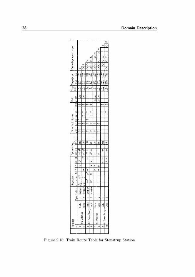
Figure 2.15 shows the train route table of Stenstrup station. This is the originaltable in Danish. The English terms are used below, but have the Danish word

2.6 Interlocking Plan 27
as reference at the first occurrence as well. The notes used in the train routetable, are shown in figure 2.16, where they have been translated to English.
The following will describe how to read a train route table. Empty fields meansthat there are no requirement to the given object in that route.
2.6.2.1 Train Routes (Togveje)
This section identifies the train routes and their purpose.
no (nr) The identifier of the train route.
Track (spor) Which station track the train route uses (not used in this project).
Overlap (forløb) Describes the end point of the overlap. If the field is empty,there is no overlap for that route. On the train route table of Stenstrupsome of the routes have “strækn” under overlap. This means that theoverlap extends from the end point of the route all the way to the openline.
2.6.2.2 Signals (Signaler)
The Signals part of the table describes the aspect each signal must show whenthe route has been locked and all the track sections in the route are vacant.If other rules require it, the signals may show other aspects, when the tracksections are occupied (see section 2.6.2.5).
gr means green, gu mean yellow and rø is red.
The entry may also contain a note, either 1, 4 or 5 from figure 2.16. Notes 4 and5 are about proceed through, which was reduced away in section 2.3.2, so theycan be ignored. However, note 1 is important. It allows a signal to show proceedif another route, with G as the start point, has been locked.
Consider train route 2 on Stenstrup. Signal A must indicate proceed, while Fand G must show stop (F flank protects and the route stops at G). G may showproceed if route 9 has been locked. There is no requirement for signals B, E andH.
28 Domain Description
Figure 2.15: Train Route Table for Stenstrup Station

2.6 Interlocking Plan 29
1) Displays proceed if an exit route has already been locked.
2) Prevented from switching for 44 sec after track circuit ↓ 03.
3) Prevented from switching for 43 sec after track circuit ↓ 01.
4) Displays proceed through if an exit route, from track 1 in the same direction,has already been locked.
5) Displays proceed through if the entry signal displays proceed through.
Figure 2.16: The translated notes of the train route table for Stenstrup (fig.2.15).
2.6.2.3 Points (Sporskifter)
The column marked Points, explains which position the points must be lockedin (if any) before the train route can be locked (The points must remain lockedwhile the train route is locked).
The + symbol means that the given points section must be locked in the plusposition, while a − would mean that the points section must be locked in theminus position.
Consider train route 2. Both points 01 and 02 (notice that it refers to the pointmachines and not the track sections) must be locked in the plus position. Pointssection 03 (with point machine 02) is not on the route, but is used as part of thesafety overlap.
2.6.2.4 Track Sections (Sporisolationer)
The track sections column lists every track section on the station. The fieldshows which state the track section relay must be in before the route can belocked. Recall that the track section relay will be in the drawn position (↑) whenthe track is clear.
Consider train route 2. The route can only be locked when all the track sectionsare vacant. Track sections 03 and B12 are used as part of the safety overlap.

30 Domain Description
2.6.2.5 Level Crossings (Ovk)
If the field is filled with “Ja” (Yes), then the level crossing must be secured.
2.6.2.6 Signal Release (Stop fald)
When the track section given in the lower part of the field is in the state given atthe same location, the signal given at the upper part of the field should changeto the stop aspect.
The fields must not be empty.
Consider train route 2. When track section A12 becomes occupied, signal Amust change to the stop aspect.
2.6.2.7 Train Route Release (Togvejsopl.)
This describes the sequence that must occur before the train route can be released.“Indl” (Initiation) states the sequence of positions the track relays must have tobegin the train route release sequence. “Opl” (Release) gives the sequence oftrack relay states that most occur for the train route release sequence to end.
The fields must not be empty.
Consider train route 2. The train route can be released when track section 01 isoccupied and track section 02 is vacant followed by 02 being occupied and 01being vacant. This means that the back end of the train has fully left 01 and isfully on 02.
Example Let us consider table 2.3 that specifies the train route release for aroute on figure 2.17. The table denotes a release sequence that has to be satisfiedto release the train route.
Train Route Release(Togvejsopl.)
Indl Opl↓ A ↓ B↑ B ↑ A
Table 2.3: Train route release for a route on figure 2.17.
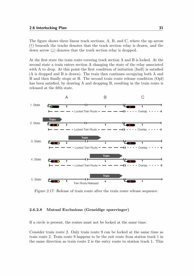
2.6 Interlocking Plan 31
The figure shows three linear track sections, A, B, and C, where the up arrow(↑) beneath the tracks denotes that the track section relay is drawn, and thedown arrow (↓) denotes that the track section relay is dropped.
At the first state the train route covering track section A and B is locked. At thesecond state a train enters section A changing the state of the relay associatedwith A to drop. At this point the first condition of initiation (Indl) is satisfied(A is dropped and B is drawn). The train then continues occupying both A andB and then finally stops at B. The second train route release condition (Opl)has been satisfied, by drawing A and dropping B, resulting in the train route isreleased at the fifth state.
Train
Locked Train Route Overlap
Locked Train Route Overlap
Locked Train Route Overlap
Train
Train
Train
Train Route Released
Locked Train Route Overlap
1. State
2. State
3. State
4. State
5. State
A B C
Figure 2.17: Release of train route after the train route release sequence.
2.6.2.8 Mutual Exclusions (Gensidige spærringer)
If a circle is present, the routes must not be locked at the same time.
Consider train route 2. Only train route 9 can be locked at the same time astrain route 2. Train route 9 happens to be the exit route from station track 1 inthe same direction as train route 2 is the entry route to station track 1. This

32 Domain Description
means that a combined route through the station can be locked for a train fromOdense.
Chapter 3
Method Description
This chapter will describe the method used to reach the goal and explain whythis method was used.
Section 3.2 introduces the steps we made in solving the problem.
3.1 Approach
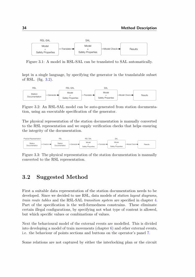
Our goal is develop a method of generating a model of external events, fromstation documentation, which can be combined with the already developed modelof internal events. The model of internal events is generated as a RSL-SALtransition system. Targeting the model of external events to RSL-SAL as well,means the models would be compatible. With the RSL to SAL translator,developed by Perna [11], the model of the entire interlocking system, acquired bycombining the two models, can then be translated to a SAL and model checked(fig. 3.1).
The RSL-SAL model of the interlocking system is to be generated from the stationdocumentation. This means a generator tool is to be developed. By specifyingboth the station documentation and the generator in RSL, the entire product is
34 Method Description
Model +
Safety PropertiesResults
RSL-SAL
Model+
Safety Properties
SAL
Translate Model Check
Figure 3.1: A model in RSL-SAL can be translated to SAL automatically.
kept in a single language, by specifying the generator in the translatable subsetof RSL. (fig. 3.2).
Model +
Safety PropertiesResults
RSL-SAL
Model+
Safety Properties
SAL
Translate Model CheckStation Documentation
RSL
Generate
Figure 3.2: An RSL-SAL model can be auto-generated from station documenta-tion, using an executable specification of the generator.
The physical representation of the station documentation is manually convertedto the RSL representation and we supply verification checks that helps ensuringthe integrity of the documentation.
Model +
Safety PropertiesResults
RSL-SAL
Model+
Safety Properties
SAL
Translate Model CheckStation Documentation
RSL
GenerateStation Documentation
Physical Representation
Creation
Figure 3.3: The physical representation of the station documentation is manuallyconverted to the RSL representation.
3.2 Suggested Method
First a suitable data representation of the station documentation needs to bedeveloped. Since we decided to use RSL, data models of station layout diagrams,train route tables and the RSL-SAL transition system are specified in chapter 4.Part of the specification is the well-formedness constrains. These eliminatecertain illegal configurations, by specifying not what type of content is allowed,but which specific values or combinations of values.
Next the behavioural model of the external events are modelled. This is dividedinto developing a model of train movements (chapter 6) and other external events,i.e. the behaviour of points sections and buttons on the operator’s panel 7.
Some relations are not captured by either the interlocking plan or the circuit

3.2 Suggested Method 35
diagrams. Chapter 8 present a structure that associates variables in the statespace of the models with the physical objects of the station.
In order to verify that the model of train movements interact correctly with themodel of the interlocking system, consistency conditions have been formulatedin chapter 9.
The main goals of this thesis is to develop a method for automated verificationof interlocking systems. A big part of this is to identify and formalise the safetyproperties of an interlocking system. This is done in chapter 10.
Up until this point, everything needed to create a model of the external eventshave been presented. Chapter 11 shows how the process can be automated bypresenting an executable specification of a generation tool.
Chapter 12 will present a test suite that verify that the well-formedness expressionscapture the intended properties.
Finally the developed method is applied to a model of Stenstrup (chapter 13).The chapter goes through the entire process of validation, from creating a digitalrepresentation of the interlocking plan, to combining the generated model ofexternal events with the model of the internal events and model checking it. Itwill also present the result of the model check.

36 Method Description

Chapter 4
Data Models
This chapter will describe the chosen data model of interlocking plans, which wasintroduced in section 2.6 and the chosen data model of RSL-SAL transition sys-tems and assertions. Furthermore, well-formedness expressions are defined, whichare used to constrain the model so that certain configurations are disallowed.
First a formal RSL specification is presented and then the data model is appliedto Stenstrup as a concrete example of how the data model is intended to beused. The entire specification of all the data models can be found in appendixE.1. The specification introduced in this chapter is slightly simplified in order tobetter present the important information.
The data model of interlocking plans is introduced in section 4.1. Then datamodels of station layout diagrams and train route tables are given in sections 4.2and 4.3 respectively. Lastly, the specification of transition systems is presentedin section 4.4.
4.1 Interlocking Plan
An interlocking plan consists of a station layout diagram and a train route table.See section E.1.2 for complete specification.

38 Data Models
typeInterlockingPlan ::
sld : Diagramtrt : TrainRouteTable
The interlocking plan is well-formed if both the station layout diagram and thetrain route table are well-formed.
valueisWfInterlockingPlan : InterlockingPlan → BoolisWfInterlockingPlan(ip) ≡
let d = sld(ip),trt = trt(ip)
in isWfDiagram(d) ∧ isWfTrainRouteTable(trt, d)end
The specification of station layout diagrams and train route tables are presentednext.
4.2 Station Layout Diagram
A data model of station layout diagrams is introduced in this section. Thecomplete specification is written in the file StationLayout.rsl, which can be foundin the appendix section E.1.3.
4.2.1 Identifiers
As described in section 2.6.1 a station layout diagram shows how a collectionof physical objects are connected in a certain configuration. Each physicalobject has its own unique identifier, which is represented as text. The physicalobjects considered in this project are track sections, point machines and signals,identifiers of which are called TrackId, PointMachineId and SignalId respectively.
typeTrackId = Text,PointMachineId = Text,SignalId = Text

4.2 Station Layout Diagram 39
Each object in each category must have an unique identifier. This is ensured bystoring them in a set structure as described in sections 4.2.4, 4.2.5 and 4.2.7.
4.2.2 Diagram
The station layout diagram is represented as a record type, which consist of setsof identifiers for the different physical objects and structures that captures theirmutual relations. Each of the constituents will be explained in the followingsections.
typeDiagram ::
line : TrackIdallLinears : TrackId-setallPoints : TrackId-setallSignals : SignalId-setneighbours : (TrackId × TrackId)-setbranchNeighbours : (TrackId × TrackId) →m BranchpointMachineTrack : PointMachineId →m TrackIdtrackPointMachine : TrackId →m PointMachineIdsignalLocations : (TrackId × TrackId) →m SignalId
where Branch is a subtype of PointsState. Recall that a points section can be ineither the plus, minus or intermediate position:
typePointsState == plus | minus | arbitrary,Branch = {| ps : PointsState • ps 6= arbitrary |},
Not every value contained in the types described above forms a valid station.The well-formedness expressions that constrains the data type to disallow certaininvalid configurations are shown below:
valueisWfDiagram : Diagram → BoolisWfDiagram(d) ≡
isWfIdentifiers(d) ∧isWfNeighbours(d) ∧

40 Data Models
isWfBranchNeighbours(d) ∧isWfPointMachines(d) ∧isWfSignalLocations(d)
A track section cannot be both a linear section and a points section.
valueisWfIdentifiers : Diagram → BoolisWfIdentifiers(d) ≡
allLinears(d) ∩ allPoints(d) = {}
The rest of the well-formedness expressions will be explained in the followingsections, when the structure they are related to, is explained.
4.2.3 Line
The line is modelled as a single track section.
valueline : TrackId = ′′line′′
The line is not part of a station as such. However, entry signals are placed onthe line at the station limits. As will be explained in further detail in section4.2.7, signals are placed between pairs of track sections, thus the line is neededas a track section to model signal location is this way.
Alternately, one could choose not to include it at all and model signal placementdifferently or make a more elaborate solution where the line is unique for eachstation exit, e.g. ”Odense” and ”Svendborg” for Stenstrup.
4.2.4 Track Sections
Each track section on a station has a unique identifier. The identifier of eachlinear section is stored in one set and the identifier of each points section is storedin another set. This is not strictly necessary, but it makes it easy to find, forexample, all the points.
4.2 Station Layout Diagram 41
valueallLinears : TrackId-set,allPoints : TrackId-set
From the station layout diagram of Stenstrup (fig. 2.14), we see a total of sixtrack sections, whereof two are points (01 and 03) and four are linears (A12, 02,04 and B12):
valueallLinears : TrackId-set = {′′A12′′, ′′02′′, ′′04′′, ′′B12′′},allPoints : TrackId-set = {′′01′′, ′′03′′}
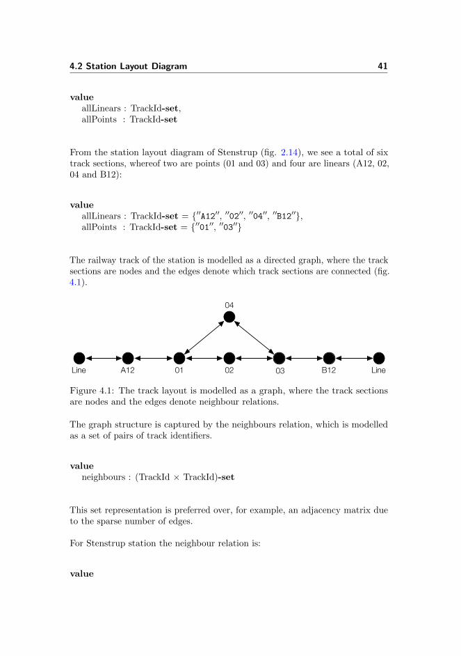
The railway track of the station is modelled as a directed graph, where the tracksections are nodes and the edges denote which track sections are connected (fig.4.1).
Line LineA12 B1201 02 03
04
Figure 4.1: The track layout is modelled as a graph, where the track sectionsare nodes and the edges denote neighbour relations.
The graph structure is captured by the neighbours relation, which is modelledas a set of pairs of track identifiers.
valueneighbours : (TrackId × TrackId)-set
This set representation is preferred over, for example, an adjacency matrix dueto the sparse number of edges.
For Stenstrup station the neighbour relation is:
value

42 Data Models
neighbours : (TrackId × TrackId)-set ={ (′′line′′, ′′A12′′), (′′A12′′, ′′01′′),
(′′01′′, ′′02′′), (′′01′′, ′′04′′),(′′02′′, ′′03′′), (′′03′′, ′′04′′),(′′03′′, ′′B12′′), (′′B12′′, ′′line′′) }
Note that the neighbours tuple contains the relationship between (tId1, tId2),but not (tId2, tId1). Doing so is to avoid having both (tId1, tId2) and (tId2, tId1)as entries, which is redundant. Instead the areNeighbours function is introducedto maintain the symmetrical entries by looking up a neighbouring relationshipboth ways.
valueareNeighbours : TrackId × TrackId × Diagram → BoolareNeighbours(tId1, tId2, d) ≡
(tId1, tId2) ∈ neighbours(d) ∨(tId2, tId1) ∈ neighbours(d)
If areNeighbours does not find the neighbour pair (tId1, tId2) it simply looksfor the pair (tId2, tId1) instead. If neither pair is in the set, then the two giventrack sections are not neighbours.
4.2.4.1 Well-formedness of neighbour relation
The following describes the validation checks performed on the data to ensurethe data model is correct.
valueisWfNeighbours : Diagram → BoolisWfNeighbours(d) ≡
neighbours OnlySections(d) ∧neighbours EverySection(d) ∧neighbours Irreflexive(d) ∧neighbours Antisymmetrical(d) ∧linears 1or2Neighbours(d) ∧points 3Neighbours(d) ∧pointsNotNeighbours(d)
4.2 Station Layout Diagram 43
1. Contains Only Track Sections The neighbour relation should containonly track sections.
valueneighbours OnlySections : Diagram → Boolneighbours OnlySections(d) ≡
( ∀ (tId1, tId2) : TrackId × TrackId •
(tId1, tId2) ∈ neighbours(d) ⇒isSection(tId1, d) ∧ isSection(tId2, d) )
2. Contains Every Track Section The neighbour relation should containevery track section on the station.
valueneighbours EverySection : Diagram → Boolneighbours EverySection(d) ≡
( ∀ tId : TrackId • tId ∈ allSections(d) ⇒( ∃ nb : TrackId • nb ∈ allSections(d) ∧
areNeighbours(tId, nb, d)) ),
where isSection is a function that returns true if the given track section is inthe given diagram, i.e. the track section is either the line, in allLinears or inallPoints.
valueisSection : TrackId × Diagram → BoolisSection(tId, d) ≡ tId ∈ allSections(d),
allSections : Diagram → TrackId-setallSections(d) ≡
allLinears(d) ∪ allPoints(d) ∪ {line(d)},
3. Irreflexive No track section may be neighbour with itself.
value
44 Data Models
neighbours Irreflexive : Diagram → Boolneighbours Irreflexive(d) ≡
( ∀ (tId1, tId2) : TrackId × TrackId •
(tId1, tId2) ∈ neighbours(d) ⇒tId1 6= tId2 )
4. Anti-symmetric Symmetrical entries are not allowed as they are not re-quired and simply clutter the set, which decreases the readability.
valueneighbours Antisymmetrical : Diagram → Boolneighbours Antisymmetrical(d) ≡
( ∀ (tId1, tId2) : TrackId × TrackId •
(tId1, tId2) ∈ neighbours(d) ⇒(tId2, tId1) 6∈ neighbours(d) )
5. Number of Neighbours - Linears Linear track sections must have atleast one neighbour and at most two.
valuelinears 1or2Neighbours : Diagram → Boollinears 1or2Neighbours(d) ≡
(∀ tId : TrackId •
tId ∈ allLinears(d) ⇒let n = card getNeighboursOf(tId, d)in n ≥ 1 ∧ n ≤ 2end)
where getNeighboursOf is a function that returns the set of all the given tracksections neighbours in the given diagram.
6. Number of Neighbours - Points Points sections must have three neigh-bours.
value
4.2 Station Layout Diagram 45
points 3Neighbours : Diagram → Boolpoints 3Neighbours(d) ≡
(∀ tId : TrackId • tId ∈ allPoints(d) ⇒card getNeighboursOf(tId, d) = 3)
7. Points sections may not be neighbours Two points sections may notbe neighbours.
valuepointsNotNeighbours : Diagram → BoolpointsNotNeighbours(d) ≡∼( ∃ (tId1, tId2) : TrackId × TrackId •
(tId1, tId2) ∈ neighbours(d) ∧isPoints(tId1, d) ∧ isPoints(tId2, d) )
4.2.5 Points
The neighbour relation models the neighbour relationship of all track sections,but it does not give any information about which branch of a point section agiven neighbour is connected to. Therefore, an additional data structure, calledbranchNeighbours, is introduced.
valuebranchNeighbours : (TrackId × TrackId) →m Branch
The idea is to label the edges between points sections and their neighbours onthe branch end. The label denotes which branch the points section and theneighbour is connected on (fig. 4.2).
The map branchNeighbours takes a pair of track ids as key and holds the branchthat they are neighbours on as value. The first track id of the key of the pair isthe id of the points section and the other is one of its neighbours on the branchside.
value

46 Data Models
Line LineA12 B1201 02 03
04
minus minus
plus plus
Figure 4.2: The branchNeighbours data structure adds information to the edgesof the neighbours relation about which branch the neighbours of a points sectionare on.
branchNeighbours : (TrackId × TrackId) →m Branch =[ (′′01′′, ′′02′′) 7→ plus,
(′′01′′, ′′04′′) 7→ minus,(′′03′′, ′′02′′) 7→ plus,(′′03′′, ′′04′′) 7→ minus ]
For example, points section 01 has linear section 02 as neighbour on the plusbranch.
4.2.5.1 Well-formedness of branchNeighbours
The branchNeigbours map is well-formed if:
1. Each pair of track sections in the domain are neighbours.
2. The first track section of the pair, is a points section.
3. There are two entries for each points section on the station.
4. The points section is not neighbour with the same track section on bothbranches.
valueisWfBranchNeighbours : Diagram → BoolisWfBranchNeighbours(d) ≡
branchNeighbours areNeighbours(d) ∧branchNeighbours FirstIsPoints(d) ∧branchNeighbours everyPoints 2branchNbs(d) ∧branchNeighbours diffNbsOnBranch(d),
4.2 Station Layout Diagram 47
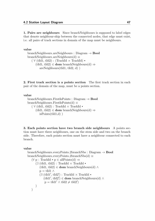
1. Pairs are neighbours Since branchNeighbours is supposed to label edgesthat denote neighbour-ship between the connected nodes, that edge must exist,i.e. all pairs of track sections in domain of the map must be neighbours.
valuebranchNeighbours areNeighbours : Diagram → BoolbranchNeighbours areNeighbours(d) ≡
( ∀ (tId1, tId2) : (TrackId × TrackId) •
(tId1, tId2) ∈ dom branchNeighbours(d) ⇒areNeighbours(tId1, tId2, d) )
2. First track section is a points section The first track section in eachpair of the domain of the map, must be a points section.
valuebranchNeighbours FirstIsPoints : Diagram → BoolbranchNeighbours FirstIsPoints(d) ≡
( ∀ (tId1, tId2) : TrackId × TrackId •
(tId1, tId2) ∈ dom branchNeighbours(d) ⇒isPoints(tId1,d) )
3. Each points section have two branch side neighbours A points sec-tion must have three neighbours, one on the stem side and two on the branchside. Therefore, each points section must have a neighbour connected to eachbranch.
valuebranchNeighbours everyPoints 2branchNbs : Diagram → BoolbranchNeighbours everyPoints 2branchNbs(d) ≡
(∀ p : TrackId • p ∈ allPoints(d) ⇒(∃ (tId1, tId2) : TrackId × TrackId •
(tId1, tId2) ∈ dom branchNeighbours(d) ∧p = tId1 ∧(∃ (tId1′, tId2′) : TrackId × TrackId •
(tId1′, tId2′) ∈ dom branchNeighbours(d) ∧p = tId1′ ∧ tId2 6= tId2′)
))

48 Data Models
4. The branch side neighbours are unique The neighbour on each branchmust be unique.
valuebranchNeighbours diffNbsOnBranch : Diagram → BoolbranchNeighbours diffNbsOnBranch(d) ≡
(∀ (p, tId1) : TrackId × TrackId •
(p, tId1) ∈ branchNeighbours(d) ⇒(∀ (p′, tId2) : TrackId × TrackId •
(p′, tId2) ∈ branchNeighbours(d) ⇒(p = p′ ∧ tId1 6= tId2 ⇒
(branchNeighbours(d)(p, tId1) = plus ∧branchNeighbours(d)(p, tId2) = minus) ∨
(branchNeighbours(d)(p, tId1) = minus ∧branchNeighbours(d)(p, tId2) = plus))))
4.2.6 Point Machines
Each points section has a point machine that control and supervise the pointssection. The point machine is a distinct entity from the points section. It has itsown identifier and has its own relays associated.
The relation of points sections and point machines are modelled with two map-pings. One from point machine ids to track ids and one the other way.
typepointMachineTrack : PointMachineId →m TrackIdtrackPointMachine : TrackId →m PointMachineId
Strictly, just one of the maps is sufficient, but look ups, in either directions, areperformed frequently enough that this data redundancy is acceptable.
Stenstrup has two points sections 01 and 03 with a point machine each, 01 and02 respectively.
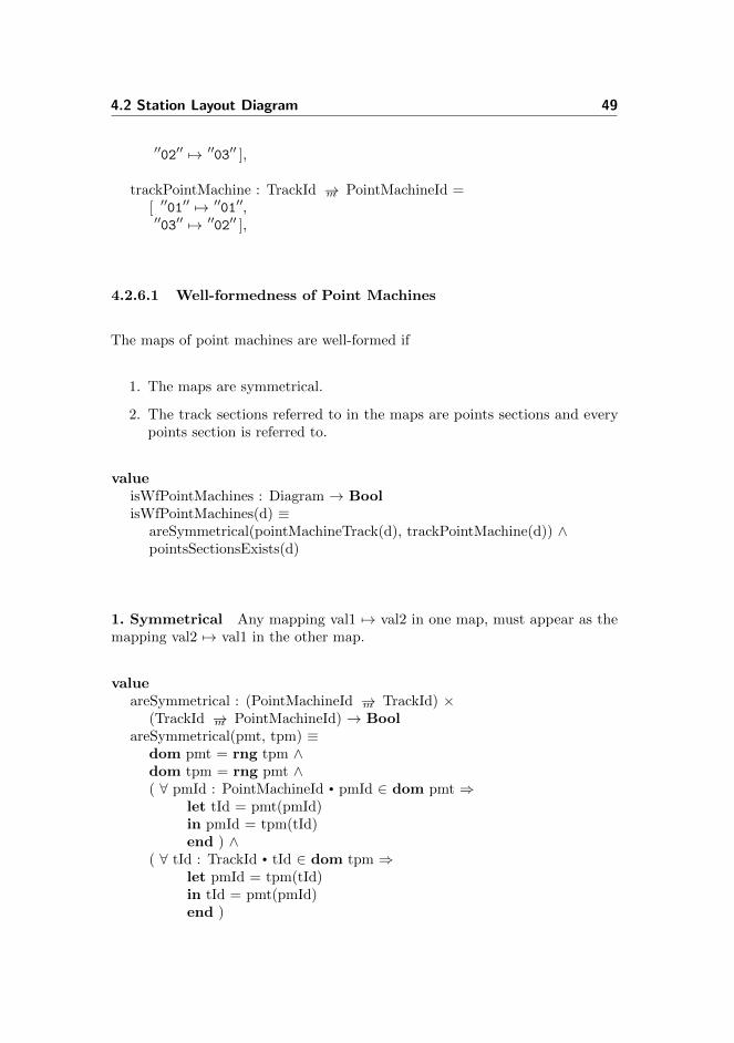
valuepointMachineTrack : PointMachineId →m TrackId =
[ ′′01′′ 7→ ′′01′′,
4.2 Station Layout Diagram 49
′′02′′ 7→ ′′03′′ ],
trackPointMachine : TrackId →m PointMachineId =[ ′′01′′ 7→ ′′01′′,′′03′′ 7→ ′′02′′ ],
4.2.6.1 Well-formedness of Point Machines
The maps of point machines are well-formed if
1. The maps are symmetrical.
2. The track sections referred to in the maps are points sections and everypoints section is referred to.
valueisWfPointMachines : Diagram → BoolisWfPointMachines(d) ≡
areSymmetrical(pointMachineTrack(d), trackPointMachine(d)) ∧pointsSectionsExists(d)
1. Symmetrical Any mapping val1 7→ val2 in one map, must appear as themapping val2 7→ val1 in the other map.
valueareSymmetrical : (PointMachineId →m TrackId) ×
(TrackId →m PointMachineId) → BoolareSymmetrical(pmt, tpm) ≡
dom pmt = rng tpm ∧dom tpm = rng pmt ∧( ∀ pmId : PointMachineId • pmId ∈ dom pmt ⇒
let tId = pmt(pmId)in pmId = tpm(tId)end ) ∧
( ∀ tId : TrackId • tId ∈ dom tpm ⇒let pmId = tpm(tId)in tId = pmt(pmId)end )

50 Data Models
Notice the lines:
dom pmt = rng tpm ∧dom tpm = rng pmt
They provide graceful error handling in our specific implementation in SML.Without them SML will throw an exception, instead of returning false, if a valueexist in one map, but not the other.
2. Existing track sections. The ids of track sections referred to in the maps,must be ids of points sections. Furthermore all points sections must have a pointmachine associated.
valuepointsSectionsExists : Diagram → BoolpointsSectionsExists(d) ≡
dom trackPointMachine(d) = allPoints(d)
4.2.7 Signals
Each signal has a unique identifier, the specification of which has already beengiven at the start of this chapter. Since the range of aspects have been reducedto just proceed and stop (section 2.3.2), there is no need to distinguish betweenthe signal types.
valueallSignals : SignalId-set,
The signals are placed between track sections1, i.e. on the edges of the graph (fig.4.3). Therefore, the location of signals is represented as a map from a neighbourpair to a signal id. This explains the need for the line construction. Without theline, the track sections on the station border would only have one neighbour. Asa result there would be no edge to put the entrance signal on.
1Actually, the signals are placed just before the separation to the signals facing side, suchthat a train will have to pass the signal in order to enter the following section.

4.2 Station Layout Diagram 51
Line LineA12 B1201 02 03
04
AE
GB
HF
Figure 4.3: The signals are located at the directed edges such that they can beread when travelling in the direction indicated by the arrow.
valuesignalLocations : (TrackId × TrackId) →m SignalId
From the station layout diagram of Stenstrup (fig. 2.14), we see that the stationhas eight signals in total. The two distant signals (a and b) are not to bemodelled, but the two entrance signals (A and B) and four exit signals (E, F, Gand H) are. The entrance and exit signals are added to the set of all signals.
valueallSignals : SignalId-set = {′′A′′, ′′B′′, ′′E′′, ′′F′′, ′′G′′, ′′H′′},
Signals are located between track sections and is only readable from one direction.Therefore they can be placed on the appropriate edge on the graph. The signalcan be read when travelling in the direction indicated by the arrow.
valuesignalLocations : (TrackId × TrackId) →m SignalId =
[ (′′line′′,′′A12′′) 7→ ′′A′′, (′′line′′,′′B12′′) 7→ ′′B′′,(′′02′′, ′′01′′) 7→ ′′E′′, (′′04′′, ′′01′′) 7→ ′′F′′,(′′02′′, ′′03′′) 7→ ′′G′′, (′′04′′, ′′03′′) 7→ ′′H′′ ],
In the example above, signal A is located between the line and A12 and readablewhen travelling from line to A12.
52 Data Models
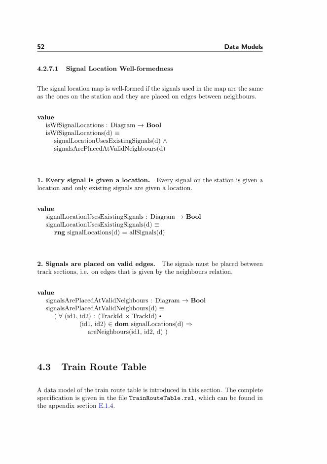
4.2.7.1 Signal Location Well-formedness
The signal location map is well-formed if the signals used in the map are the sameas the ones on the station and they are placed on edges between neighbours.
valueisWfSignalLocations : Diagram → BoolisWfSignalLocations(d) ≡
signalLocationUsesExistingSignals(d) ∧signalsArePlacedAtValidNeighbours(d)
1. Every signal is given a location. Every signal on the station is given alocation and only existing signals are given a location.
valuesignalLocationUsesExistingSignals : Diagram → BoolsignalLocationUsesExistingSignals(d) ≡
rng signalLocations(d) = allSignals(d)
2. Signals are placed on valid edges. The signals must be placed betweentrack sections, i.e. on edges that is given by the neighbours relation.
valuesignalsArePlacedAtValidNeighbours : Diagram → BoolsignalsArePlacedAtValidNeighbours(d) ≡
( ∀ (id1, id2) : (TrackId × TrackId) •
(id1, id2) ∈ dom signalLocations(d) ⇒areNeighbours(id1, id2, d) )
4.3 Train Route Table
A data model of the train route table is introduced in this section. The completespecification is given in the file TrainRouteTable.rsl, which can be found inthe appendix section E.1.4.
4.3 Train Route Table 53
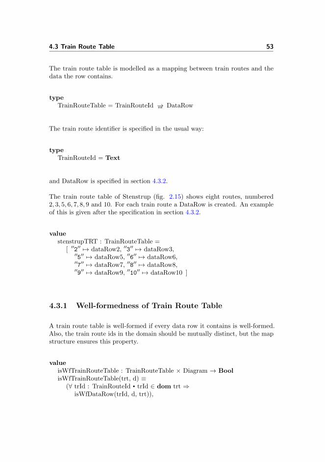
The train route table is modelled as a mapping between train routes and thedata the row contains.
typeTrainRouteTable = TrainRouteId →m DataRow
The train route identifier is specified in the usual way:
typeTrainRouteId = Text
and DataRow is specified in section 4.3.2.
The train route table of Stenstrup (fig. 2.15) shows eight routes, numbered2, 3, 5, 6, 7, 8, 9 and 10. For each train route a DataRow is created. An exampleof this is given after the specification in section 4.3.2.
valuestenstrupTRT : TrainRouteTable =
[ ′′2′′ 7→ dataRow2, ′′3′′ 7→ dataRow3,′′5′′ 7→ dataRow5, ′′6′′ 7→ dataRow6,′′7′′ 7→ dataRow7, ′′8′′ 7→ dataRow8,′′9′′ 7→ dataRow9, ′′10′′ 7→ dataRow10 ]
4.3.1 Well-formedness of Train Route Table
A train route table is well-formed if every data row it contains is well-formed.Also, the train route ids in the domain should be mutually distinct, but the mapstructure ensures this property.
valueisWfTrainRouteTable : TrainRouteTable × Diagram → BoolisWfTrainRouteTable(trt, d) ≡
(∀ trId : TrainRouteId • trId ∈ dom trt ⇒isWfDataRow(trId, d, trt)),

54 Data Models
4.3.2 DataRow
The data in each row is stored in a record type called DataRow. Each part of thetrain route table gets its own entry and are described in detail in the followingsections.
typeDataRow ::
overlap : TrackId-setsignals : SignalId →m Aspectpoints : PointMachineId →m PointsStatetrainDetection : TrackId →m BoolsignalRelease : SignalId × TrackIdtrainRouteRelease : ReleaseSequencemutuallyBlocking : TrainRouteId →m Bool,
As an example, consider train route 2 on Stenstrup. The creation of each ofthe constituents are shown separately in the following sections to improve thereadability.
valuedataRow2 : DataRow =
mk DataRow(overlap2,signals2,points2,trainDetection2,signalRelease2,trainRouteRelease2,mutuallyBlocking2
),
4.3.2.1 Well-formedness of DataRow
A data row is well-formed if each of its constituents are well-formed.
value
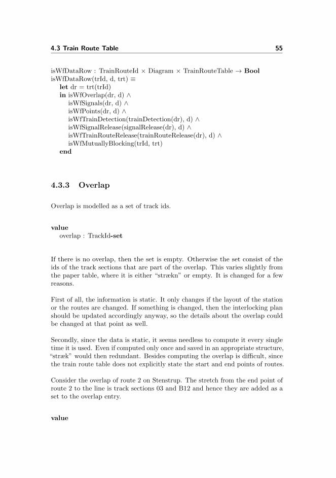
4.3 Train Route Table 55
isWfDataRow : TrainRouteId × Diagram × TrainRouteTable → BoolisWfDataRow(trId, d, trt) ≡
let dr = trt(trId)in isWfOverlap(dr, d) ∧
isWfSignals(dr, d) ∧isWfPoints(dr, d) ∧isWfTrainDetection(trainDetection(dr), d) ∧isWfSignalRelease(signalRelease(dr), d) ∧isWfTrainRouteRelease(trainRouteRelease(dr), d) ∧isWfMutuallyBlocking(trId, trt)
end
4.3.3 Overlap
Overlap is modelled as a set of track ids.
valueoverlap : TrackId-set
If there is no overlap, then the set is empty. Otherwise the set consist of theids of the track sections that are part of the overlap. This varies slightly fromthe paper table, where it is either “strækn” or empty. It is changed for a fewreasons.
First of all, the information is static. It only changes if the layout of the stationor the routes are changed. If something is changed, then the interlocking planshould be updated accordingly anyway, so the details about the overlap couldbe changed at that point as well.
Secondly, since the data is static, it seems needless to compute it every singletime it is used. Even if computed only once and saved in an appropriate structure,“stræk” would then redundant. Besides computing the overlap is difficult, sincethe train route table does not explicitly state the start and end points of routes.
Consider the overlap of route 2 on Stenstrup. The stretch from the end point ofroute 2 to the line is track sections 03 and B12 and hence they are added as aset to the overlap entry.
value

56 Data Models
overlap2 : TrackId-set = {′′03′′, ′′B12′′}
4.3.3.1 Well-formnedess of Overlap
If the following hold, the overlap is considered well-formed.
1. If there is an overlap for a given route, then the track sections of the overlapmust be vacant when the route is locked.
2. If there is an overlap, the track sections of the overlap must form a connectedpath.
3. If there is an overlap, then it must be an extension of the route, i.e. onlyone section of the overlap may be neighbour with a section from the route.
valueisWfOverlap : DataRow × Diagram → BoolisWfOverlap(dr, d) ≡
let overlap = overlap(dr)in card overlap > 0 ⇒
overlapCovered(overlap, trainDetection(dr)) ∧overlapIsConnected(overlap, d) ∧endOfRoute(dr, d)
end
1. Overlap Sections in Train Detection Track sections which are part ofthe overlap, must be covered by the route.
valueoverlapCovered : TrackId-set × (TrackId →m Bool) → BooloverlapCovered(overlap, trainDetection) ≡
overlap ⊆ coveredSections(trainDetection)
where the covered track sections, are the sections that are required to be vacant,when the route is locked.

4.3 Train Route Table 57
valuecoveredSections : (TrackId →m Bool) → TrackId-setcoveredSections(trainDetection) ≡{ tId | tId : TrackId • tId ∈ dom trainDetection ∧
trainDetection(tId)},
2. Overlap is connected Any non-empty overlap, must form a connectedpath.
valueoverlapIsConnected : TrackId-set × Diagram → BooloverlapIsConnected(overlap, d) ≡
areConnected(overlap, d)
where is a function that attempts to create a connected path through the set oftrack sections it is given, using the neighbour relation from the station layoutdiagram it is given as input.
valueareConnected : TrackId-set × Diagram → BoolareConnected(sections, d) ≡
if sections = {} then true elselet s = hd sections, sections′ = sections \ {s}in findConnected({s}, {s}, sections, d) = sectionsend
end,
findConnected : TrackId-set × TrackId-set ×TrackId-set × Diagram → TrackId-set
findConnected(queue, visited, sectionsInRoute, d) ≡if queue = {} then visited else
let q = hd queue,nbs = getNeighboursOf(q, d) ∩ sectionsInRoute,queue′ = (queue \ {q}) ∪ (nbs \ visited),visited′ = visited ∪ {q}
in findConnected(queue′, visited′, sectionsInRoute, d)end
end

58 Data Models
3. Overlap is extension The overlap must be an extension of the route, i.e.there is only a single track section from the overlap, which is neighbour with atrack section from the route.
valueendOfRoute : DataRow × Diagram → BoolendOfRoute(dr, d) ≡
let overlap = overlap(dr),coveredSections = coveredSections(trainDetection(dr)),route = coveredSections \ overlap
in ( ∃! tId : TrackId • tId ∈ overlap ∧let nbs = getNeighboursOf(tId, d),
nbsInOverlap = nbs ∩ routein card nbsInOverlap ≥ 1end
)end
4.3.4 Signals
The signals section is specified as a mapping from each signal on the station torequired aspect.
valuesignals : SignalId →m Aspect
Recall from section 2.3.2 that the possible aspects has been reduced to proceedand stop. These are modelled as gr and re respectively. If there is no requirementto the aspect, arbitrary can written.
typeAspect == gr | re | arbitrary,
Consider the signals part for train route 2 on Stenstrup. We see that signal Ais required to show proceed, while F and G should show stop. There are norequirements about the aspect of the rest of the signals.

4.3 Train Route Table 59
valuesignals2 : SignalId →m Aspect =
[ ′′A′′ 7→ gr, ′′B′′ 7→ arbitrary, ′′E′′ 7→ arbitrary,′′F′′ 7→ re, ′′G′′ 7→ re, ′′H′′ 7→ arbitrary ]
4.3.4.1 Well-formedness of Signals
Every signal on the station must be present as keys to the map structure.Furthermore the entry signal must show proceed aspect.
valueisWfSignals : DataRow × Diagram → BoolisWfSignals(dr, d) ≡
let signals = signals(dr)in existingSignals(signals, d) ∧
proceedEntry(getEntrySignal(dr), signals)end
where the entry signal is extracted from the signal release entry.
valuegetEntrySignal : DataRow → SignalIdgetEntrySignal(dr) ≡
let (sId, tId) = signalRelease(dr) in sId end
1. Existing Signals
valueexistingSignals : (SignalId →m Aspect) × Diagram → BoolexistingSignals(signals, d) ≡
dom signals = allSignals(d)

60 Data Models
2. Entry Signal Shows Proceed
valueproceedEntry : SignalId × (SignalId →m Aspect) → BoolproceedEntry(entrySignal, signals) ≡
signals(entrySignal) = gr
4.3.5 Points
The part of the train route table called Points is modelled as a map from the idof each point machine to the required position of the points section, if any.
valuepoints : PointMachineId →m PointsState
where PointsState is defined as
typePointsState == plus | minus | arbitrary
Consider train route 2 on Stenstrup. Both points must be set to plus.
valuepoints : PointMachineId →m PointsState = [ ′′01′′ 7→ plus, ′′02′′ 7→ plus ]
4.3.5.1 Well-formedness of Points
The points part of the train route table is well-formed if:
1. Any track section associated with a point machine is part of the station.
2. For every points section, its associated point machine is in points.
3. Every points section on the route has a required position.

4.3 Train Route Table 61
4. The point position matches the route.
valueisWfPoints : DataRow × Diagram → BoolisWfPoints(dr, d) ≡
let points = points(dr)in pointMachinesExist(dom points, d) ∧
pointMachinesInTRT(dr, d) ∧pointsInRouteLocked(dr, d) ∧correctPos(dr, d)
end
1. Point machines exist The point machines in the train route table are alsodefined in the station layout diagram.
valuepointMachinesExist : PointMachineId-set × Diagram → BoolpointMachinesExist(points, d) ≡
( ∀ pId : PointMachineId • pId ∈ points ⇒pId ∈ dom pointMachineTrack(d) ∧let tId = pointMachineTrack(d)(pId)in tId ∈ allPoints(d)end )
2. Point machine given The point machine associated with each pointssection of the station, must be in the points section of the train route table.
valuepointMachinesInTRT : DataRow × Diagram → BoolpointMachinesInTRT(dr, d) ≡
( ∀ tId : TrackId •
tId ∈ dom trainDetection(dr) ⇒isPoints(tId, d) ⇒
let pmId = trackPointMachine(d)(tId)in pmId ∈ dom points(dr)end ),
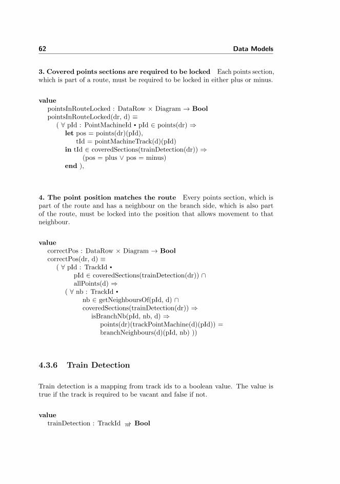
62 Data Models
3. Covered points sections are required to be locked Each points section,which is part of a route, must be required to be locked in either plus or minus.
valuepointsInRouteLocked : DataRow × Diagram → BoolpointsInRouteLocked(dr, d) ≡
( ∀ pId : PointMachineId • pId ∈ points(dr) ⇒let pos = points(dr)(pId),
tId = pointMachineTrack(d)(pId)in tId ∈ coveredSections(trainDetection(dr)) ⇒
(pos = plus ∨ pos = minus)end ),
4. The point position matches the route Every points section, which ispart of the route and has a neighbour on the branch side, which is also partof the route, must be locked into the position that allows movement to thatneighbour.
valuecorrectPos : DataRow × Diagram → BoolcorrectPos(dr, d) ≡
( ∀ pId : TrackId •
pId ∈ coveredSections(trainDetection(dr)) ∩allPoints(d) ⇒
( ∀ nb : TrackId •
nb ∈ getNeighboursOf(pId, d) ∩coveredSections(trainDetection(dr)) ⇒
isBranchNb(pId, nb, d) ⇒points(dr)(trackPointMachine(d)(pId)) =branchNeighbours(d)(pId, nb) ))
4.3.6 Train Detection
Train detection is a mapping from track ids to a boolean value. The value istrue if the track is required to be vacant and false if not.
valuetrainDetection : TrackId →m Bool
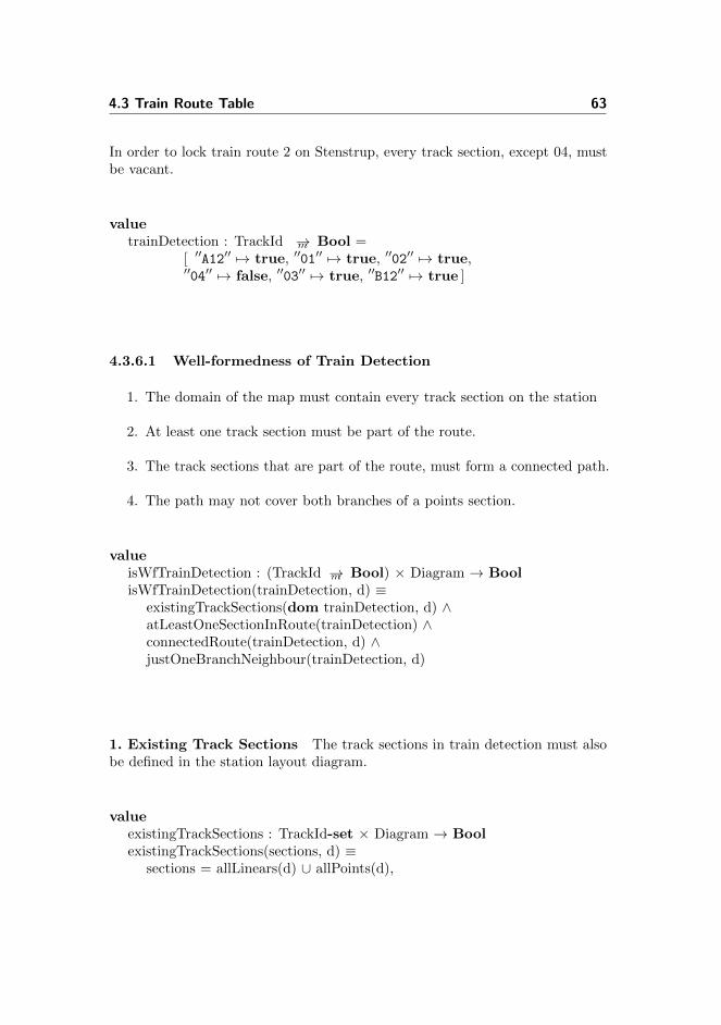
4.3 Train Route Table 63
In order to lock train route 2 on Stenstrup, every track section, except 04, mustbe vacant.
valuetrainDetection : TrackId →m Bool =
[ ′′A12′′ 7→ true, ′′01′′ 7→ true, ′′02′′ 7→ true,′′04′′ 7→ false, ′′03′′ 7→ true, ′′B12′′ 7→ true ]
4.3.6.1 Well-formedness of Train Detection
1. The domain of the map must contain every track section on the station
2. At least one track section must be part of the route.
3. The track sections that are part of the route, must form a connected path.
4. The path may not cover both branches of a points section.
valueisWfTrainDetection : (TrackId →m Bool) × Diagram → BoolisWfTrainDetection(trainDetection, d) ≡
existingTrackSections(dom trainDetection, d) ∧atLeastOneSectionInRoute(trainDetection) ∧connectedRoute(trainDetection, d) ∧justOneBranchNeighbour(trainDetection, d)
1. Existing Track Sections The track sections in train detection must alsobe defined in the station layout diagram.
valueexistingTrackSections : TrackId-set × Diagram → BoolexistingTrackSections(sections, d) ≡
sections = allLinears(d) ∪ allPoints(d),

64 Data Models
2. At Least One Section In Route At least one of the track sections intrain detection must be part of the route.
valueatLeastOneSectionInRoute : (TrackId →m Bool) → BoolatLeastOneSectionInRoute(trainDetection) ≡
(∃ b : Bool • b ∈ rng trainDetection ∧ b)
3. Connected The track sections in the route, must form a connected path.
valueconnectedRoute : (TrackId →m Bool) × Diagram → BoolconnectedRoute(trainDetection, d) ≡
areConnected(coveredSections(trainDetection), d)
4. No path over both branches A train cannot travel from one branch tothe other on a points section. Therefore routes may not have this configurationeither.
valuejustOneBranchNeighbour :
(TrackId →m Bool) × Diagram → BooljustOneBranchNeighbour(trainDetection, d) ≡
( ∀ tId : TrackId •
tId ∈ coveredSections(trainDetection) ⇒/∗ Only interrested in points sections ∗/isPoints(tId, d) ⇒
/∗ Does not have two branch side neighbour ∗/∼( ∃ bNb1 : TrackId •
bNb1 ∈ coveredSections(trainDetection) ∧isBranchNb(tId, bNb1, d) ∧( ∃ bNb2 : TrackId •
bNb2 ∈ coveredSections(trainDetection) ∧isBranchNb(tId, bNb2, d) ∧bNb1 6= bNb2 )
))

4.3 Train Route Table 65
4.3.7 Signal Release
Signal release is modelled as a pair of a signal id and a track id.
valuesignalRelease : SignalId × TrackId
When the given track becomes occupied, the given signal will be forced to releaseback to stop. The down arrow shown in the train route table is not modelled, asit is always the case that it is dropped when the track section is occupied.
In train route 2 on Stenstrup, signal A should release back to stop when tracksection A12 becomes occupied.
valuesignalRelease : SignalId × TrackId = ( ′′A′′, ′′A12′′ )
4.3.7.1 Well-formedness of Signal Release
The given signal id must match a signal on the station and the track section mustbe part of the station. Furthermore, that signal must be on an edge betweenthat track section and another and must be readable when travelling from thetrack section to its neighbour.
valueisWfSignalRelease : (SignalId × TrackId) × Diagram → BoolisWfSignalRelease((sId, tId), d) ≡
sId ∈ allSignals(d) ∧tId ∈ allLinears(d) ∪ allPoints(d) ∧signalFollowedByTrackSection(sId, tId, d),
where the given track section ts is directly after the signal if there exist anothertrack section ts′ such that the given signal is located on the edge going from ts′
to ts.

66 Data Models
valuesignalFollowedByTrackSection : SignalId × TrackId × Diagram → BoolsignalFollowedByTrackSection(sId, tId, d) ≡
(∃ tId2 : TrackId • tId2 ∈ allSections(d) ∧(tId2, tId) ∈ dom signalLocations(d) ∧
signalLocations(d)(tId2, tId) = sId)
4.3.8 Train Route Release
Train Route Release is modelled as a pair of release condition pairs.
valuetrainRouteRelease : ReleaseSequence
typeReleaseSequence = ReleaseCond × ReleaseCond,ReleaseCond = (TrackId × RelayState) × (TrackId × RelayState)
A release condition pair consists of a track id and a relay state, which can beeither drawn or dropped.
typeRelayState == drawn | dropped,
Consider train route 2 on Stenstrup. The route is released when track section 01is occupied, while track section 02 is vacant, followed by 01 being vacant and 02occupied.
valuetrainRouteRelease : ReleaseSequence =
( ((′′01′′, dropped), (′′02′′, drawn)),((′′02′′, dropped), (′′01′′, drawn)) )

4.3 Train Route Table 67
4.3.8.1 Well-formedness of Train Route Release
The release sequence follow a strict pattern. First the first track section of therelease sequence must occupied, while the second is vacant. Then the secondtrack section must be occupied, while the first is vacant.
valueisWfTrainRouteRelease : DataRow × Diagram → BoolisWfTrainRouteRelease(dr, d) ≡
let (indl, opl) = trainRouteRelease(dr),((tId1, rs1), (tId2, rs2)) = indl,((tId3, rs3), (tId4, rs4)) = opl
in reverseTrackSections(tId1, tId2, tId3, tId4) ∧reverseRelayState(rs1, rs2, rs3, rs4) ∧trackSectionPartOfRoute(tId1, dr) ∧trackSectionPartOfRoute(tId2, dr) ∧properRelayState(rs1, rs2) ∧areNeighbours(tId1, tId2, d)
end
Therefore, for the sequence to be well-formed, the track sections in the firstrelease condition, must be same as in the second condition.
valuereverseTrackSections : TrackId × TrackId ×
TrackId × TrackId → BoolreverseTrackSections(tId1, tId2, tId3, tId4) ≡
tId1 = tId4 ∧ tId2 = tId3
The track sections must be part of the route.
valuetrackSectionPartOfRoute : TrackId × DataRow → BooltrackSectionPartOfRoute(tId, dr) ≡
tId ∈ sectionsInRoute(trainDetection(dr)),
The state of the relays must follow the pattern dropped, drawn, dropped, drawn.

68 Data Models
valuereverseRelayState : RelayState × RelayState ×
RelayState × RelayState → BoolreverseRelayState(rs1, rs2, rs3, rs4) ≡
rs1 = rs3 ∧ rs2 = rs4,
properRelayState : RelayState × RelayState → BoolproperRelayState(rs1, rs2) ≡
rs1 = dropped ∧ rs2 = drawn
4.3.9 Mutually Blocking
Mutually blocking is a mapping from train route ids to a boolean value. If thevalue is true, then the routes are conflicting with each other.
valuemutuallyBlocking : TrainRouteId →m Bool
Train route 2 on Stenstrup conflicts with every other train route except for route9.
valuemutuallyBlocking : TrainRouteId →m Bool =[ ′′2′′ 7→ true, ′′3′′ 7→ true, ′′5′′ 7→ true, ′′6′′ 7→ true,
′′7′′ 7→ true, ′′8′′ 7→ true, ′′9′′ 7→ false, ′′10′′ 7→ true ]
Well-formedness of Mutually Blocking Mutually Blocking is well-formedif:
1. Must have an entry for every train route and no other.
2. If two routes share at least one track section, which is in neither routesoverlap, then the two routes are conflicting.
3. If two routes require different positioning of a points section, then the tworoutes are conflicting.
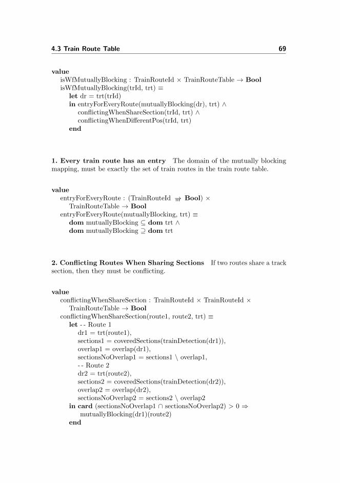
4.3 Train Route Table 69
valueisWfMutuallyBlocking : TrainRouteId × TrainRouteTable → BoolisWfMutuallyBlocking(trId, trt) ≡
let dr = trt(trId)in entryForEveryRoute(mutuallyBlocking(dr), trt) ∧
conflictingWhenShareSection(trId, trt) ∧conflictingWhenDifferentPos(trId, trt)
end
1. Every train route has an entry The domain of the mutually blockingmapping, must be exactly the set of train routes in the train route table.
valueentryForEveryRoute : (TrainRouteId →m Bool) ×
TrainRouteTable → BoolentryForEveryRoute(mutuallyBlocking, trt) ≡
dom mutuallyBlocking ⊆ dom trt ∧dom mutuallyBlocking ⊇ dom trt
2. Conflicting Routes When Sharing Sections If two routes share a tracksection, then they must be conflicting.
valueconflictingWhenShareSection : TrainRouteId × TrainRouteId ×
TrainRouteTable → BoolconflictingWhenShareSection(route1, route2, trt) ≡
let - - Route 1dr1 = trt(route1),sections1 = coveredSections(trainDetection(dr1)),overlap1 = overlap(dr1),sectionsNoOverlap1 = sections1 \ overlap1,- - Route 2dr2 = trt(route2),sections2 = coveredSections(trainDetection(dr2)),overlap2 = overlap(dr2),sectionsNoOverlap2 = sections2 \ overlap2
in card (sectionsNoOverlap1 ∩ sectionsNoOverlap2) > 0 ⇒mutuallyBlocking(dr1)(route2)
end
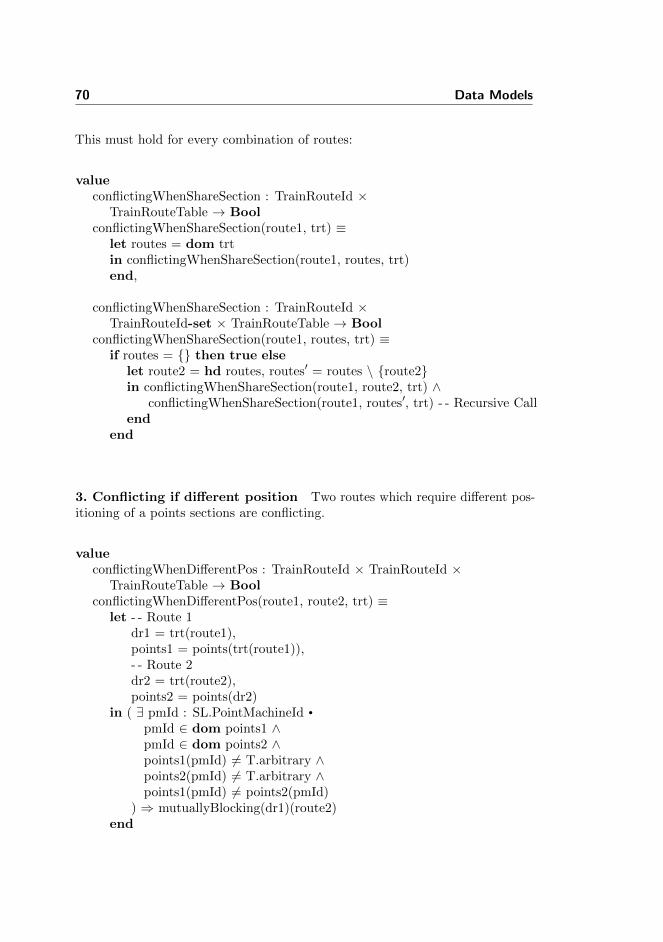
70 Data Models
This must hold for every combination of routes:
valueconflictingWhenShareSection : TrainRouteId ×
TrainRouteTable → BoolconflictingWhenShareSection(route1, trt) ≡
let routes = dom trtin conflictingWhenShareSection(route1, routes, trt)end,
conflictingWhenShareSection : TrainRouteId ×TrainRouteId-set × TrainRouteTable → Bool
conflictingWhenShareSection(route1, routes, trt) ≡if routes = {} then true else
let route2 = hd routes, routes′ = routes \ {route2}in conflictingWhenShareSection(route1, route2, trt) ∧
conflictingWhenShareSection(route1, routes′, trt) - - Recursive Callend
end
3. Conflicting if different position Two routes which require different pos-itioning of a points sections are conflicting.
valueconflictingWhenDifferentPos : TrainRouteId × TrainRouteId ×
TrainRouteTable → BoolconflictingWhenDifferentPos(route1, route2, trt) ≡
let - - Route 1dr1 = trt(route1),points1 = points(trt(route1)),- - Route 2dr2 = trt(route2),points2 = points(dr2)
in ( ∃ pmId : SL.PointMachineId •
pmId ∈ dom points1 ∧pmId ∈ dom points2 ∧points1(pmId) 6= T.arbitrary ∧points2(pmId) 6= T.arbitrary ∧points1(pmId) 6= points2(pmId)
) ⇒ mutuallyBlocking(dr1)(route2)end
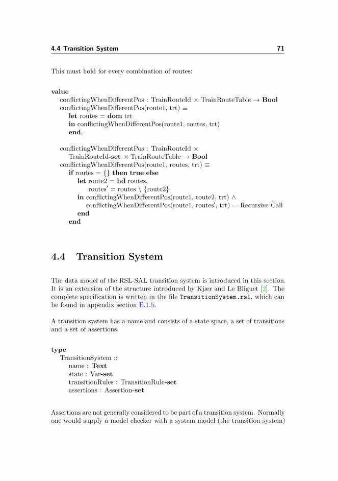
4.4 Transition System 71
This must hold for every combination of routes:
valueconflictingWhenDifferentPos : TrainRouteId × TrainRouteTable → BoolconflictingWhenDifferentPos(route1, trt) ≡
let routes = dom trtin conflictingWhenDifferentPos(route1, routes, trt)end,
conflictingWhenDifferentPos : TrainRouteId ×TrainRouteId-set × TrainRouteTable → Bool
conflictingWhenDifferentPos(route1, routes, trt) ≡if routes = {} then true else
let route2 = hd routes,routes′ = routes \ {route2}
in conflictingWhenDifferentPos(route1, route2, trt) ∧conflictingWhenDifferentPos(route1, routes′, trt) - - Recursive Call
endend
4.4 Transition System
The data model of the RSL-SAL transition system is introduced in this section.It is an extension of the structure introduced by Kjær and Le Bliguet [2]. Thecomplete specification is written in the file TransitionSystem.rsl, which canbe found in appendix section E.1.5.
A transition system has a name and consists of a state space, a set of transitionsand a set of assertions.
typeTransitionSystem ::
name : Textstate : Var-settransitionRules : TransitionRule-setassertions : Assertion-set
Assertions are not generally considered to be part of a transition system. Normallyone would supply a model checker with a system model (the transition system)

72 Data Models
and a property specification (assertions). However, we wanted to be able togenerate both the transition system and the assertions with a single call tothe generator. With assertions as part of the transition system, the generatorcan pass both the transition system and the assertions directly to the unparser.Alternatively, a wrapper structure that contains the transition system and theassertions could solve the same problem.
A transition system is well-formed if the name, the state space, the transitionsand the assertions are all well-formed.
valueisWfTransitionSystem : TransitionSystem → BoolisWfTransitionSystem(ts) ≡
isWfName(name(ts)) ∧isWfState(state(ts)) ∧isWfTransitionRules(ts) ∧isWfAssertions(assertions(ts))
4.4.1 Transition System Name
The transition system may not have the empty string as name.
valueisWfName : Text → BoolisWfName(name) ≡
name 6= ′′′′
4.4.2 State Space
The state space is a set of variables. A variable have an identifier and a value.
typeVar ::
id : VarIdval : Val

4.4 Transition System 73
where the id of the variable is modelled as text:
typeVarId = Text
and the value can be either of type boolean or natural number.
Val == mk BoolVal(b : Bool) | mk NatVal(n : Nat)
These are the value types used in the behavioural model, which is introduced insection 6.2. Additional could be added if needed.
4.4.2.1 Well-formedness of State Space
The state space is well-formed if each variable has a unique id and the id of eachvariable is valid.
valueisWfState : Var-set → BoolisWfState(vars) ≡ uniqueIds(vars) ∧ validIds(vars)
1. Unique Ids An id is unique if there does not exist another variable in thesame state space with the same id.
valueuniqueIds : Var-set → BooluniqueIds(vars) ≡
( ∀ var1 : Var • var1 ∈ vars ⇒∼( ∃ var2 : Var • var2 ∈ vars ∧
id(var1) = id(var2) ∧ var1 6= var2))
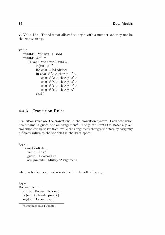
74 Data Models
2. Valid Ids The id is not allowed to begin with a number and may not bethe empty string.
valuevalidIds : Var-set → BoolvalidIds(vars) ≡
( ∀ var : Var • var ∈ vars ⇒id(var) 6= ′′′′ ∧let char = hd id(var)in char 6= ′0′ ∧ char 6= ′1′ ∧
char 6= ′2′ ∧ char 6= ′3′ ∧char 6= ′4′ ∧ char 6= ′5′ ∧char 6= ′6′ ∧ char 6= ′7′ ∧char 6= ′8′ ∧ char 6= ′9′
end )
4.4.3 Transition Rules
Transition rules are the transitions in the transition system. Each transitionhas a name, a guard and an assignment2. The guard limits the states a giventransition can be taken from, while the assignment changes the state by assigningdifferent values to the variables in the state space.
typeTransitionRule ::
name : Textguard : BooleanExpassignments : MultipleAssignment
where a boolean expression is defined in the following way:
typeBooleanExp ==
and(a : BooleanExp-set) |or(o : BooleanExp-set) |neg(n : BooleanExp) |2Sometimes called update.

4.4 Transition System 75
lessthan(ArithmeticExp, ArithmeticExp) |greaterthan(ArithmeticExp, ArithmeticExp) |geq(ArithmeticExp, ArithmeticExp) | /∗ greater than equal∗/equals(ArithmeticExp, ArithmeticExp) |literal(id : VarId) |bool(b : Bool)
using the following definition of arithmetic expressions:
typeArithmeticExp ==
add(a : ArithmeticExp-set) |sub(s : ArithmeticExp-set) |literal(l : VarId),
The update part of a transition rule consists of a set of assignments as well:
typeMultipleAssignment = Assignment-set,
Assignment ::id : VarIdassign : AssignExp,
AssignExp == BoolAssign(ba : Bool) |NatAssign(na : Nat) |AddAssign(aa : Nat) |SubAssign(sa : Nat) ,
4.4.3.1 Well-formedness of Transition Rules
The following must hold for transitions.
1. Names must be valid.
2. Names must be unique.
3. Value assignments to existing variables.

76 Data Models
4. Variables in guard must be part of the state space.
5. At least one assignment in update.
6. Each variable may only be updated once.
valueisWfTransitionRules : TransitionSystem → BoolisWfTransitionRules(ts) ≡
let state = state(ts),trs = transitionRules(ts)
in validNames(trs) ∧uniqueNames(trs) ∧assignmentToExistingIds(ts) ∧idsInGuardMustBeInState(state, trs) ∧nonemptyAssignment(trs) ∧idUpdOnlyOnce(trs)
end
1. Names must be nonempty The empty string is not a valid name for atransition rule.
valuevalidNames : TransitionRule-set → BoolvalidNames(trs) ≡
( ∀ tr : TransitionRule • tr ∈ trs ⇒∼isEmptyString(name(tr))
)
2. Names must be unique Two transitions with the same name may notexist.
valueuniqueNames : TransitionRule-set → BooluniqueNames(trs) ≡
( ∀ tr1 : TransitionRule • tr1 ∈ trs ⇒∼( ∃ tr2 : TransitionRule • tr2 ∈ trs ∧
tr1 6= tr2 ∧ name(tr1) = name(tr2) ))

4.4 Transition System 77
3. Value assignments to existing variables Any value assignment in atransition rule, must be to a variable in the state space of the same transitionsystem.
valueassignmentToExistingIds : TransitionSystem → BoolassignmentToExistingIds(ts) ≡
( ∀ tr : TransitionRule • tr ∈ transitionRules(ts) ⇒( ∀ assign : Assignment • assign ∈ assignments(tr) ⇒
( ∃ var : Var • var ∈ state(ts) ∧id(assign) = id(var) )
))
4. Variables in guard must be part of the state space The variablesused in each guard, must be part of the state space.
valueidsInGuardMustBeInState : Var-set × TransitionRule-set → BoolidsInGuardMustBeInState(state, trs) ≡
( ∀ tr : TransitionRule • tr ∈ trs ⇒( ∀ id : VarId • id ∈ idsInBoolExp(guard(tr)) ⇒
( ∃ var : Var • var ∈ state ∧id = id(var) )
))
5. At least one assignment in update The empty assignment is not allowed.
valuenonemptyAssignment : TransitionRule-set → BoolnonemptyAssignment(trs) ≡
( ∀ tr : TransitionRule • tr ∈ trs ⇒assignments(tr) 6= {}
)

78 Data Models
6. Each variable may only be updated once Each variable may only beupdated once in any transition rule.
valueidUpdOnlyOnce : TransitionRule-set → BoolidUpdOnlyOnce(trs) ≡
( ∀ tr : TransitionRule • tr ∈ trs ⇒let ma = assignments(tr)in ( ∀ assign : Assignment • assign ∈ ma ⇒∼( ∃ assign2 : Assignment • assign2 ∈ ma ∧
assign 6= assign2 ∧ id(assign) = id(assign2) ))
end)
4.4.4 Assertions
An assertion consists of a name and a LTL formula.
typeAssertion = Text × LTLformula
where an LTL formula has been defined in the following way.
typeLTLformula ==
b(bExp : BooleanExp) |ltrl(l : Text) | /∗ Literal ∗/conj(LTLformula-set) | /∗ Conjunction ∗/disj(LTLformula-set) | /∗ Disjunction ∗/paren(LTLformula) | /∗ Parenthesis ∗/neg(LTLformula) | /∗ Negation ∗/impl(LTLformula, LTLformula) | /∗ Implication ∗/x(LTLformula) | /∗ Next ∗/g(LTLformula) | /∗ Globally ∗/f(LTLformula) | /∗ Finally ∗/u(LTLformula, LTLformula) /∗ Until ∗/

4.4 Transition System 79
This differs from the syntax used by Kjær and Le Bliguet [2] and thus somework is required here, if the specifications are to be merged. The reason for thechange is that they only allow LTL operators at the outer levels. As will be seenin section 10.8, expressions like ♦(A ∧©B) will be needed.
The definition of the LTL syntax consists of a subset of the above definedLTLformula of temporal and logical operators. Most of them are derived fromthe fundamental definitions described by Baier and Katoen [3]. The scope for thisproject is not to derive the grammar, but use the LTL formulae to generate theexpressions. Thus, for convenience all the needed temporal and logical operatorsused in generating the assertions are defined in the LTLformula type.
4.4.4.1 Well-formedness of Assertions
An assertion is well-formed if its name is unique among the assertions in thetransition system and the name is non-empty. Furthermore, any variables in theLTL formula must exist in the state space.
valueisWfAssertions : TransitionSystem → BoolisWfAssertions(ts) ≡
let state = state(ts),assertions = assertions(ts)
in nonemptyNames(assertions) ∧uniqueNames(assertions) ∧existingVars(state, assertions)
end
1. Valid name Assertion name must be non-empty.
valuenonemptyNames : Assertion-set → BoolnonemptyNames(assertions) ≡
( ∀ (name, ltl) : Assertion • (name, ltl) ∈ assertions ⇒name 6= ′′′′ )
Assertion name must be unique.

80 Data Models
valueuniqueNames : Assertion-set → BooluniqueNames(assertions) ≡
( ∀ (name, ltl) : Assertion • (name, ltl) ∈ assertions ⇒∼( ∃ (name2, ltl2) : Assertion •
(name2, ltl2) ∈ assertions ∧(name, ltl) 6= (name2, ltl2) ∧name = name2 )
)
2. Existing variables The variables used in the LTL expression must be partof the state space of the transition system.
valueexistingVars : Var-set × Assertion-set → BoolexistingVars(state, assertions) ≡
( ∀ (name, ltl) : Assertion • (name, ltl) ∈ assertions ⇒( ∀ id : T.VarId • id ∈ idsInLTL(ltl) ⇒
isIdInState(id, state) ))

Chapter 5
Behavioural Model of theInternal System
This chapter will describe the behavioural model of the internal part of theinterlocking system.
This model was developed by Kjær and Le Bliguet [2]. The model will bedescribed briefly, with an emphasis on the concrete model of Stenstrup that theycreated using their generator tool. For a deeper understanding of the model andchoices made in creating it, we refer to their thesis.
Section 5.1 introduces the state space. Here the relevant variables will beexplained and associated with entities from the station documentation.
Section 5.2 will briefly the transition rules of the internal system. These are notas relevant for this work, as the external environment does not interact with thetransitions, but rather the variables of the state space.
Lastly, section 5.3 will describe how time is modelled. This section is highlyrelevant, as it affects every external event.

82 Behavioural Model of the Internal System
5.1 State Space
The state of the model of the internal interlocking system contains a booleanvariable for each relay and each button. The variable is true when the relay isdrawn or button is pushed respectively and false when the relay is dropped orbutton is released respectively.
The initial value of the variables are the state of the relay/button in the normalstate.
5.1.1 State Space of Stenstrup
Table 5.1 shows the relevant subset of the 60 boolean variables created by thegenerator of the internal system, when Stenstrup station is given as input.
Type Variable State
Track a12, t01, t02, t03, t04, b12 False when the related track sec-tion is occupied.
Points plus01, minus01, plus02,minus02
True when the related pointssection is locked into the givenposition.
Signals aGreen, aRed, bGreen, bRed,eGreen, eRed, fGreen, fRed,gGreen, gRed, hGreen, hRed
True when the given light, ofthe related signal, is on.
Locking ia, ib, ua, ub False when the related trainroute is locked.
Buttons b00406, b00606, b03106,b03306
True when the related but-ton on the operator’s panel ispressed. Used to lock routes.
Table 5.1: Variables used in the internal model of the relay interlocking systemat Stenstrup station.
Table 5.2 shows the relation between each track section on Stenstrup and thegenerated track relay variables, which models the corresponding track section’strack relay.
Each point machine has two point detection relays, one for the plus positionand one for the minus position. Table 5.3 shows the relation between the pointmachines on Stenstrup and the generated point detection relay variables.
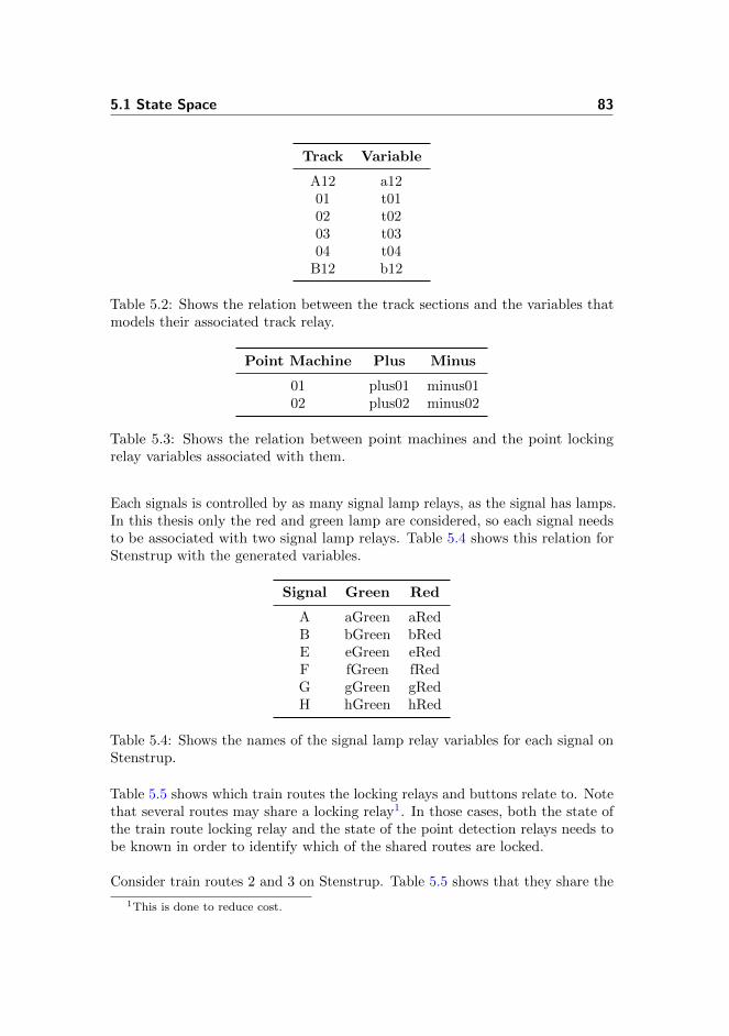
5.1 State Space 83
Track Variable
A12 a1201 t0102 t0203 t0304 t04
B12 b12
Table 5.2: Shows the relation between the track sections and the variables thatmodels their associated track relay.
Point Machine Plus Minus
01 plus01 minus0102 plus02 minus02
Table 5.3: Shows the relation between point machines and the point lockingrelay variables associated with them.
Each signals is controlled by as many signal lamp relays, as the signal has lamps.In this thesis only the red and green lamp are considered, so each signal needsto be associated with two signal lamp relays. Table 5.4 shows this relation forStenstrup with the generated variables.
Signal Green Red
A aGreen aRedB bGreen bRedE eGreen eRedF fGreen fRedG gGreen gRedH hGreen hRed
Table 5.4: Shows the names of the signal lamp relay variables for each signal onStenstrup.
Table 5.5 shows which train routes the locking relays and buttons relate to. Notethat several routes may share a locking relay1. In those cases, both the state ofthe train route locking relay and the state of the point detection relays needs tobe known in order to identify which of the shared routes are locked.
Consider train routes 2 and 3 on Stenstrup. Table 5.5 shows that they share the
1This is done to reduce cost.

84 Behavioural Model of the Internal System
Train Routes Locking Relay Button
2, 3 ia b006065, 6 ib b031067, 8 ua b004069, 10 ub b03306
Table 5.5: Shows which locking relays and which buttons on the operators panelrelate to which train routes.
same train route locking relay. However, train route 2 require the point machines01 and 02 to be locking in the plus position, while train route 3 require the pointmachines to be locking in the minus position. Since the points must be lockedinto position before a train route can be locked, the state of the points determinewhich route is locked, when pressing button b00606.
5.2 Transition Rules
Two transition rules are generated for each relay. One allows the relay to bedrawn, while the other allows the relay to be dropped.
The guards are inferred from the logic of the circuitry and can thus be very long.The update on the other hand is always quite simple. It just switches the stateof the relay.
5.3 The Timing Issue
SAL uses LTL as its property specification language, but LTL does not offer anexplicit notion of time. Time in LTL is abstracted to a series of discrete eventsthat happens in a linear manner. This means that LTL can express propertiesabout the relative order of events, but not the precise timing. Therefore, it canbe expressed that a button is released after it has been pressed, but not that thebutton is released 1 second after being pressed.
In the electrical relay circuitry the current would (likely) propagate throughthe closed contact of the pressed button faster than the operator can releasethe button again. This means that the internal events that the current triggers,should occur prior to the external event that the button is released. This leads

5.3 The Timing Issue 85
to the assumption that internal events happen so quickly, in relation to externalevents, that any possible internal event should be allowed to happen before thenext external event can occur.
5.3.1 Idle and Busy States
This issue is resolved by introducing the concept of idle and busy states of thesystem. The system is busy if internal events are possible and idle if not (fig.5.1).
Idle Busy
External Event
Internal Event
Busy Busy Idle Busy Busy Idle Idle Busy Idle
Figure 5.1: The initial state of the internal interlocking system is the idle state.Here the system waits for external events to occur. When an external eventoccurs, the system switches to the busy state, where only internal events mayoccur. When no further internal events can occur, the system returns to the idlestate. [2]
Therefore, any external event must have the rule that:
• An external event can only occur if the interlocking system is in the idlestate.
In order to allow the relays to react to the external event, the system must beset to being busy whenever an external event takes place:
• Any external event results in the system being busy.
The system is then busy as long as it is possible for an internal event to occur.When this is no longer the case, the system becomes idle again:
• The system becomes idle once no internal event can occur.
86 Behavioural Model of the Internal System
On a practical level, this leads to the introduction of the artificial boolean variableidle, which is true when the system is idle and false when the system is busy, andthe transition setIdle, which sets idle to true if no internal transition is available.
Idle is initialised to true, since no internal event can occur in the normal state.
5.3.2 Returning To the Idle State
The system can return to the idle state, when no further internal events canoccur. The generator of the internal system generates a transition rule calledsetIdle, which has the signature:
[ setIdle ] ∼idle ∧ ∼<allInternalGuards> −→idle′ = true
where 〈allInternalGuards〉 is the conjunction of all the guards of the internaltransitions.
The interlocking system includes a function that allows it to consider a pressedbutton as released even though its not. This functionality activates if a buttonis not released within a reasonable amount of time. This functionality is notmodelled in the internal system, but is instead simulated by the following updateto the setIdle transition, which is not generated by the generator of the internalmodel. Therefore, it is necessary to manually replace the setIdle update withthe content shown below:
idle′ = ∼(b00406 ∨ b00606 ∨ b03106 ∨ b03306),b00406′ = false,b00606′ = false,b03106′ = false,b03306′ = false

Chapter 6
Behavioural Model of TrainMovements
The following chapter will briefly discuss approaches to modelling train move-ments, where section 6.1 will introduce two models and discuss their differences,and why one model is chosen over the other.
The chosen model of train movements consists of two parts. A model representa-tion of trains discussed in section 6.2 and a model of the train movement rulesin section 6.3.
6.1 Approaches to Modelling Train Movement
The idea behind introducing new approaches is to solve the limitation of themodel of train movement used by Kjær and Le Bliguet [2].
Let us shortly recap their model. It uses a direction and location of trainsby assigning a boolean variable for each track section. For instance, considerStenstrup, if a train is at section a12 and heading towards Svendborg, the variablea12 fwd would be true. If the train proceeds to 01 and therefore occupies both a12and 01, a12 t01 fwd would be true. This requires a variable for each permutation

88 Behavioural Model of Train Movements
of location, direction and train length. Avoiding a large state space they limitedthe trains to have a maximum length of two sections.
All in all their model is excellent in its simplicity, but with the major limitationthat it is too specific, and therefore require a boolean variable for each possiblesituation.
During the modelling phase of train movements two approaches were considered.The first model can be found in appendix D. Recapping this approach, it uses alocation variable containing all the track sections a train occupies in a set anda direction variable which points to a neighbouring track section the train isheading towards. When the train is moving the location set is updated as wellas the direction variable.
Having this approach it eliminates the limitation of train length, and allows oneto dictate movement behaviour specific for each train, since trains are explicitlycreated. Thus, creating several trains requires behaviours for each train. Thedownside of this approach is, that the model checker is limited to the number ofdefined trains.
In the early stages of modelling train movement there were conducted severaltests to compare the model of fixed train movement1 with the explicit modeland with the implicit model, which will be introduced in the following section.The comparison was in terms of elapsed time and memory consumption whenmodel checking. The test showed, as illustrated on figure 6.1, that the implicitmodel was slightly slower than the fixed train model, and faster than the twocases compared with the explicit train model.
Measurements
Model Condition Time Memory (MB)
Fixed train length Basic safety 15 sec 76TRT safety 2.36 min 121
Implict train Basic safety 16 sec 83TRT safety 3.00 min 140
Explicit train Basic safety 21 sec 81TRT safety 4.25 min 138
Table 6.1: Model checked train models showing the time spend and memoryconsumption.
As mentioned earlier, the rest of this chapter will present the implicit model, that
1The model provided by Kjær and Le Bliguet
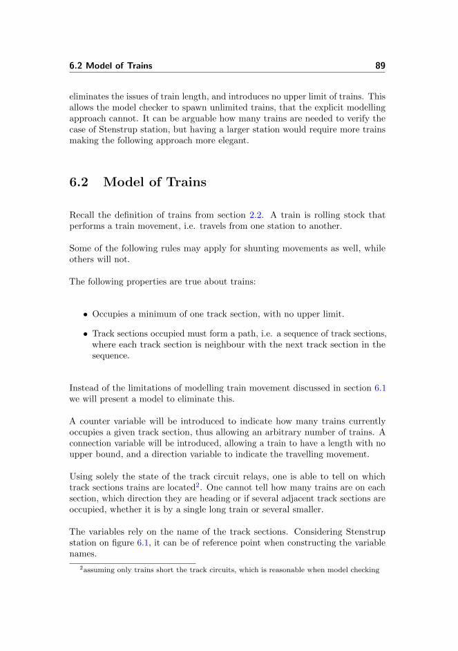
6.2 Model of Trains 89
eliminates the issues of train length, and introduces no upper limit of trains. Thisallows the model checker to spawn unlimited trains, that the explicit modellingapproach cannot. It can be arguable how many trains are needed to verify thecase of Stenstrup station, but having a larger station would require more trainsmaking the following approach more elegant.
6.2 Model of Trains
Recall the definition of trains from section 2.2. A train is rolling stock thatperforms a train movement, i.e. travels from one station to another.
Some of the following rules may apply for shunting movements as well, whileothers will not.
The following properties are true about trains:
• Occupies a minimum of one track section, with no upper limit.
• Track sections occupied must form a path, i.e. a sequence of track sections,where each track section is neighbour with the next track section in thesequence.
Instead of the limitations of modelling train movement discussed in section 6.1we will present a model to eliminate this.
A counter variable will be introduced to indicate how many trains currentlyoccupies a given track section, thus allowing an arbitrary number of trains. Aconnection variable will be introduced, allowing a train to have a length with noupper bound, and a direction variable to indicate the travelling movement.
Using solely the state of the track circuit relays, one is able to tell on whichtrack sections trains are located2. One cannot tell how many trains are on eachsection, which direction they are heading or if several adjacent track sections areoccupied, whether it is by a single long train or several smaller.
The variables rely on the name of the track sections. Considering Stenstrupstation on figure 6.1, it can be of reference point when constructing the variablenames.
2assuming only trains short the track circuits, which is reasonable when model checking
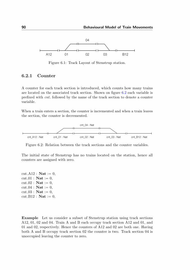
90 Behavioural Model of Train Movements
A12 01 02 03 B12
04
Figure 6.1: Track Layout of Stenstrup station.
6.2.1 Counter
A counter for each track section is introduced, which counts how many trainsare located on the associated track section. Shown on figure 6.2 each variable isprefixed with cnt followed by the name of the track section to denote a countervariable.
When a train enters a section, the counter is incremented and when a train leavesthe section, the counter is decremented.
cnt_A12 : Nat
cnt_04 : Nat
cnt_B12 : Natcnt_03 : Natcnt_02 : Natcnt_01 : Nat
Figure 6.2: Relation between the track sections and the counter variables.
The initial state of Stenstrup has no trains located on the station, hence allcounters are assigned with zero.
cnt A12 : Nat := 0,cnt 01 : Nat := 0,cnt 02 : Nat := 0,cnt 04 : Nat := 0,cnt 03 : Nat := 0,cnt B12 : Nat := 0,
Example Let us consider a subset of Stenstrup station using track sectionsA12, 01, 02 and 04. Train A and B each occupy track section A12 and 01, and01 and 02, respectively. Hence the counters of A12 and 02 are both one. Havingboth A and B occupy track section 02 the counter is two. Track section 04 isunoccupied leaving the counter to zero.
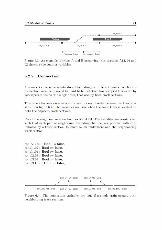
6.2 Model of Trains 91
Train B
cnt_01 = 2 cnt_02 = 1
Train A
cnt_A12 = 1
cnt_04 = 0
Occupied Track Unoccupied Track
Figure 6.3: An example of trains A and B occupying track sections A12, 01 and02 showing the counter variables.
6.2.2 Connection
A connection variable is introduced to distinguish different trains. Without aconnection variable it would be hard to tell whether two occupied tracks are bytwo separate trains or a single train, that occupy both track sections.
This time a boolean variable is introduced for each border between track sectionsshown on figure 6.4. The variables are true when the same train is located onboth the adjacent track sections.
Recall the neighbour relation from section 4.2.4. The variables are constructedsuch that each pair of neighbours, excluding the line, are prefixed with confollowed by a track section, followed by an underscore and the neighbouringtrack section.
con A12 01 : Bool := false,con 01 02 : Bool := false,con 01 04 : Bool := false,con 02 03 : Bool := false,con 03 04 : Bool := false,con 03 B12 : Bool := false,
con_A12_01 : Bool con_01_02 : Bool con_02_03 : Bool con_03_B12 : Bool
con_01_04 : Bool con_04_03 : Bool
Figure 6.4: The connection variables are true if a single train occupy bothneighbouring track sections.

92 Behavioural Model of Train Movements
Example Let us consider the same scenario on Stenstrup station in the examplein section 6.2.1. Figure 6.5 shows that train A occupies section A12 and 01,hence con A12 01 is true. While train B occupies 01 and 02 hence con 01 02 istrue. There is no connection between 01 and 04 leaving con 01 04 false.
Using the connection variable in conjunction with the counter variable it can bederived that there are two trains, since the counter for track section 01 is two.Thus, one train connected with A12 and 01 and another connected with 01 and02.
Train A
con_A12_01 = true con_01_02 = true
con_01_04 = false
Occupied Track Unoccupied Track
Train B
Figure 6.5: An example of train A and B occupying track sections A12, 01 and02 showing the connection variables.
6.2.3 Direction
The direction variable denotes the travelling movement of trains. Each tracksection has two direction variables prefixed with fwd and bwd followed by atrack name, where fwd is short for forward and bwd is short for backward. Figure6.6 shows the complete set of direction variables for Stenstrup station.
Whenever one of the variables is true then a train on the associated track sectionis heading in one direction, while the other is true when a train on the sametrack section is heading the other way. They are false if there is no train on thesection or if no train on the section is heading in the given direction.
Moving from Odense to Svendborg denotes a travelling direction of forward andmoving from Svendborg to Odense is backward.
fwd A12 : Bool := false,bwd A12 : Bool := false
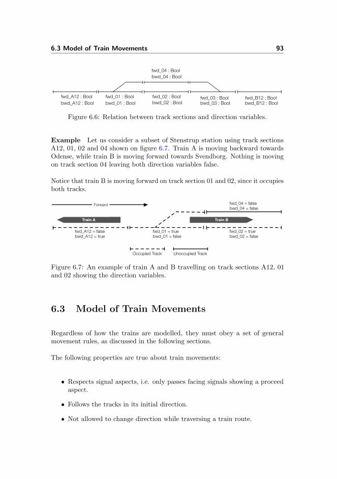
6.3 Model of Train Movements 93
fwd_A12 : Bool fwd_01 : Bool fwd_02 : Boolbwd_03 : Bool
fwd_B12 : Bool
fwd_04 : Bool
bwd_01 : Boolbwd_A12 : Bool
bwd_04 : Bool
bwd_02 : Boolfwd_03 : Bool
bwd_B12 : Bool
Figure 6.6: Relation between track sections and direction variables.
Example Let us consider a subset of Stenstrup station using track sectionsA12, 01, 02 and 04 shown on figure 6.7. Train A is moving backward towardsOdense, while train B is moving forward towards Svendborg. Nothing is movingon track section 04 leaving both direction variables false.
Notice that train B is moving forward on track section 01 and 02, since it occupiesboth tracks.
Train BTrain A
Occupied Track Unoccupied Track
fwd_A12 = falsebwd_A12 = true
fwd_01 = truebwd_01 = false
fwd_02 = truebwd_02 = false
Forward fwd_04 = falsebwd_04 = false
Figure 6.7: An example of train A and B travelling on track sections A12, 01and 02 showing the direction variables.
6.3 Model of Train Movements
Regardless of how the trains are modelled, they must obey a set of generalmovement rules, as discussed in the following sections.
The following properties are true about train movements:
• Respects signal aspects, i.e. only passes facing signals showing a proceedaspect.
• Follows the tracks in its initial direction.
• Not allowed to change direction while traversing a train route.

94 Behavioural Model of Train Movements
6.3.1 Enter Station
A train is allowed to enter a station at track section ts, if ts is at the stationlimit and the entrance signal covering ts shows a proceed aspect.
The general rule for entering a station has the following form.
[ enter ts from line ] idle ∧ sGreen ∧ ∼sRed −→idle′ = false, ts′ = false,cnt ts′ = cnt ts + 1, dir ts′ = true
where ts is a track sections and dir is either fwd or bwd. sGreen and sRed aresignal relays for signal s.
In the example below a rule for entering a station will be constructed andexplained step by step showing the requirements before a train is allowed toenter and which parameters that the train affects when doing so.
Example Let us consider the following case on Stenstrup station when enteringthe station on track section A12 from the line. External events can happenonly when the system is idle, which is the first requirement for any external rule.While any action that requires the internal system to respond on external eventsthe system is no longer idle.
Hence, this can be applied as a template for constructing a rule for enteringStenstrup station.
[ enter A12 from line ] idle ∧ ... −→idle′ = false, ...
The only requirement for a train to enter a station is that the entry signal showsa proceed aspect. Again, using Stenstrup this requires that the entry signal Amust show proceed aspect and not stop aspect.
[ enter A12 from line ] idle ∧ aGreen ∧ ∼aRed −→idle′ = false, ...
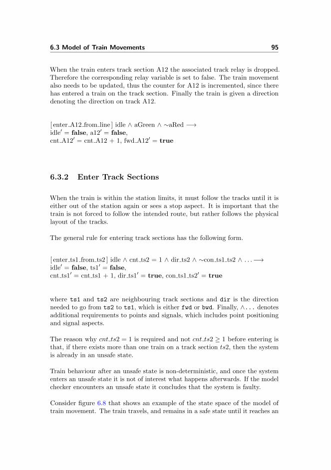
6.3 Model of Train Movements 95
When the train enters track section A12 the associated track relay is dropped.Therefore the corresponding relay variable is set to false. The train movementalso needs to be updated, thus the counter for A12 is incremented, since therehas entered a train on the track section. Finally the train is given a directiondenoting the direction on track A12.
[ enter A12 from line ] idle ∧ aGreen ∧ ∼aRed −→idle′ = false, a12′ = false,cnt A12′ = cnt A12 + 1, fwd A12′ = true
6.3.2 Enter Track Sections
When the train is within the station limits, it must follow the tracks until it iseither out of the station again or sees a stop aspect. It is important that thetrain is not forced to follow the intended route, but rather follows the physicallayout of the tracks.
The general rule for entering track sections has the following form.
[ enter ts1 from ts2 ] idle ∧ cnt ts2 = 1 ∧ dir ts2 ∧ ∼con ts1 ts2 ∧ . . .−→idle′ = false, ts1′ = false,cnt ts1′ = cnt ts1 + 1, dir ts1′ = true, con ts1 ts2′ = true
where ts1 and ts2 are neighbouring track sections and dir is the directionneeded to go from ts2 to ts1, which is either fwd or bwd. Finally, ∧... denotesadditional requirements to points and signals, which includes point positioningand signal aspects.
The reason why cnt ts2 = 1 is required and not cnt ts2 ≥ 1 before entering isthat, if there exists more than one train on a track section ts2, then the systemis already in an unsafe state.
Train behaviour after an unsafe state is non-deterministic, and once the systementers an unsafe state it is not of interest what happens afterwards. If the modelchecker encounters an unsafe state it concludes that the system is faulty.
Consider figure 6.8 that shows an example of the state space of the model oftrain movement. The train travels, and remains in a safe state until it reaches an
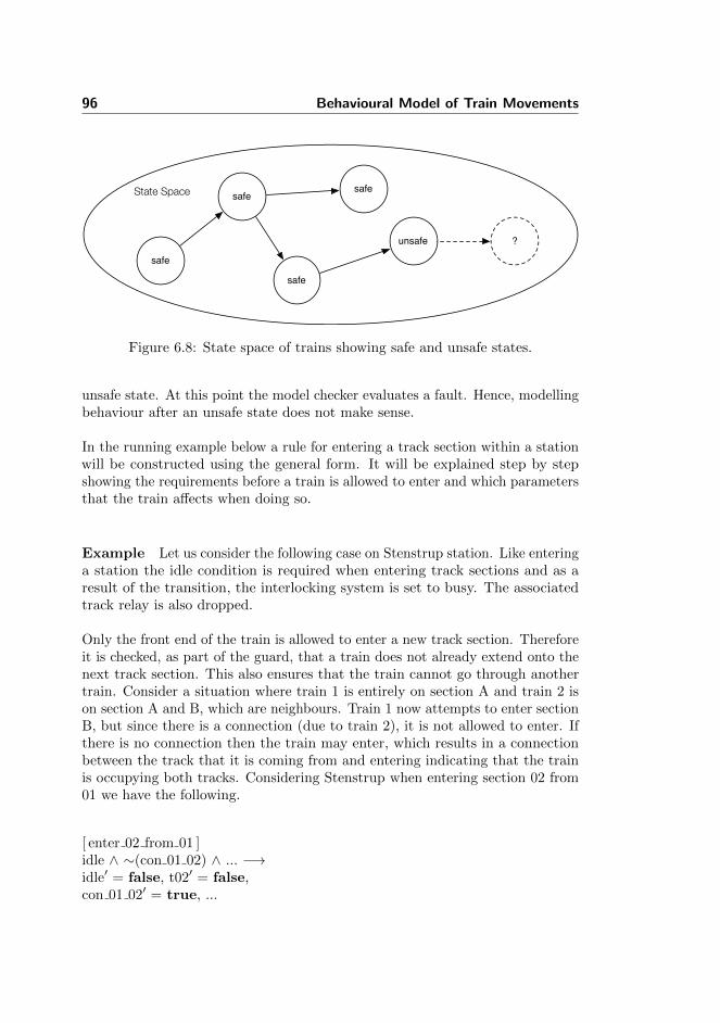
96 Behavioural Model of Train Movements
State Space safe
safe
safe
safe
unsafe ?
Figure 6.8: State space of trains showing safe and unsafe states.
unsafe state. At this point the model checker evaluates a fault. Hence, modellingbehaviour after an unsafe state does not make sense.
In the running example below a rule for entering a track section within a stationwill be constructed using the general form. It will be explained step by stepshowing the requirements before a train is allowed to enter and which parametersthat the train affects when doing so.
Example Let us consider the following case on Stenstrup station. Like enteringa station the idle condition is required when entering track sections and as aresult of the transition, the interlocking system is set to busy. The associatedtrack relay is also dropped.
Only the front end of the train is allowed to enter a new track section. Thereforeit is checked, as part of the guard, that a train does not already extend onto thenext track section. This also ensures that the train cannot go through anothertrain. Consider a situation where train 1 is entirely on section A and train 2 ison section A and B, which are neighbours. Train 1 now attempts to enter sectionB, but since there is a connection (due to train 2), it is not allowed to enter. Ifthere is no connection then the train may enter, which results in a connectionbetween the track that it is coming from and entering indicating that the trainis occupying both tracks. Considering Stenstrup when entering section 02 from01 we have the following.
[ enter 02 from 01 ]idle ∧ ∼(con 01 02) ∧ ... −→idle′ = false, t02′ = false,con 01 02′ = true, ...
6.3 Model of Train Movements 97
A train may only enter a track section if it is already occupying the neighbouringtrack it is coming from. Hence, the track counter of the neighbouring trackmust be equal to one. This condition is to avoid the scenario where a train justsuddenly appear out of nowhere. Additionally the counter for the track that isentered to is incremented by one to denote that a train is occupying the track.
[ enter 02 from 01 ]idle ∧ cnt 01 = 1 ∧ ∼(con 01 02) ∧ ... −→idle′ = false, t02′ = false,cnt 02′ = cnt 02 + 1, con 01 02′ = true, ...
When entering track section 02 from 01 the direction on track section 01 mustbe forward. Resulting to the direction of 02 being forward as well.
[ enter 02 from 01 ]idle ∧ cnt 01 = 1 ∧ fwd 01 ∧ ∼(con 01 02) ∧ ... −→idle′ = false, t02′ = false,cnt 02′ = cnt 02 + 1, fwd 02′ = true, con 01 02′ = true
It is only physical possible for a train to enter track section 02 if the positioningof point 01 is in plus. Thus, the last requirement for entering track section 02 iswhen the point positioning is set to plus.
[ enter 02 from 01 ]idle ∧ cnt 01 = 1 ∧ fwd 01 ∧ ∼(con 01 02) ∧ plus01 −→idle′ = false, t02′ = false,cnt 02′ = cnt 02 + 1, fwd 02′ = true, con 01 02′ = true
Summarizing the above. A train may enter a track section ts if the front of thetrain is at a neighbouring track section ts′ and the train is heading towards ts.Additionally, if a signal s is located on ts′ and covers ts, the train may enter tsonly if the signal shows a proceed aspect.
sGreen ∧ ∼sRed
This requirement is added as a guard if there is a signal s covering a track section.Additionally, rules for entering points sections depends on the trains entry point.All these rules are explained in the following sections.

98 Behavioural Model of Train Movements
6.3.2.1 Travelling on Points Sections
The entry point on a points section matters greatly, both in relation to wherethe train ends up and in relation to safety. When entering from the stem side,the train will travel by the plus branch if the points section is locked in the plusposition and likewise with the minus position. However, if the points section isnot locked into position, i.e. is in the intermediate position, then the train runsthe risk of derailing.
When entering from the branch side, the train risk derailing not only whenthe points section is not locked, but also when it is locked in the other branchposition.
Recalling from figure 2.4 that showed the notion of a facing and a trailing move.A facing move is when a train enters the stem side or leaves the branch, while atrailing move is when a train enters the branch side or leaves the stem.
Facing Move - Stem Side A facing move onto a points section or a facingmove to the neighbour of a points section is treated the same way as moving onlinear sections.
Consider the following cases on Stenstrup. The following transition rule describesthe situation, where a train is entering the points section 01 from the linearsection A12.
[ enter 01 from A12 ] idle ∧ cnt A12 = 1 ∧ fwd A12 ∧ ∼con A12 01 −→idle′ = false, t01′ = false,cnt 01′ = cnt 01 + 1, con A12 01′ = true, fwd 01′ = true
Notice that it follows the same pattern as movement on linear track sections.However, the same cannot be said about movements that involve the branch sideof a points section.
Facing Move - Branch Side When entering the neighbouring track sectionfrom one of the branches of a points section, the position of the points has to beconsidered. It is a regular enter rule except that it requires the points section tobe locked into position. Travelling from 01 to 02 requires the point to be lockedin the plus position, which directs the train towards track section 02.
6.3 Model of Train Movements 99
[ enter 02 from 01 ] idle ∧ cnt 01 = 1 ∧ fwd 01 ∧ ∼con 01 02 ∧ plus01 −→idle′ = false, t02′ = false,cnt 02′ = cnt 02 + 1, con 01 02′ = true, fwd 02′ = true
When a points section is in an intermediate state, while a train is in the act of afacing move at the branch side the outcome is non-deterministic. The train mayrisk a derailment or it may continue an unknown path, since the points are justabout to lock into a position, for instance. Referring back to figure 6.8 it is notof interest what happens after an unsafe state, hence the case of an intermediatepoints position will be left out.
Trailing Move - Stem Side A facing move at the stem side is similar toa trailing move at the stem side. The following transition rule describes thesituation, where a train is entering the linear section A12 from the points section01.
[ enter A12 from 01 ] idle ∧ cnt 01 = 1 ∧ bwd 01 ∧ ∼con A12 01 −→idle′ = false, a12′ = false,cnt A12′ = cnt A12 + 1, con A12 01′ = true, bwd A12′ = true
Notice once again, that it follows the same pattern as movement on linear tracksections.
Trailing Move - Branch Side Entering a points section on the branch siderequires two transition rules to cover the cases. If the correct branch is locked,then the train will not derail and and proceed as normal. On the other hand, ifthe points are in the intermediate position or locked to the wrong branch, thenthe train will run the risk of derailing.
Consider the following rules for Stenstrup. A train enters to points section 01from section 02. The rules follow the same pattern as before, but with an addedrequirement about the position of the points. This ensures that the case wherethe train travels without derailing is applied. Since there is located a signalcovering the points section, the proceed aspect requirement is added as well.
[ enter 01 from 02 no derail ] idle ∧ cnt 02 = 1 ∧ bwd 02 ∧∼con 01 02 ∧ eGreen ∧ ∼eRed ∧ plus01 −→
idle′ = false, t01′ = false,
100 Behavioural Model of Train Movements
cnt 01′ = cnt 01 + 1, con 01 02′ = true,bwd 01′ = true,
The second case is when a train enters the same points section, but the pointspositioning is not in plus i.e. either intermediate or minus.
[ enter 01 from 02 derail ] idle ∧ cnt 02 = 1 ∧ bwd 02 ∧∼con 01 02 ∧ eGreen ∧ ∼eRed ∧ ∼plus01 −→
idle′ = false, t01′ = false,cnt 01′ = cnt 01 + 1, con 01 02′ = true
Notice that the train is not assigned a direction when it derails3.
6.3.3 Leave Station
A train is allowed to leave a station if the back end of the train occupies a tracksection ts, which is located at the station limit, and it is heading towards theline.
The general rule for leaving a station has the following form.
[ leave ts to line ] idle ∧ cnt ts = 1 ∧ dir ts ∧ ∼con tsNeighbour ts −→idle′ = false, ts′ = true,cnt ts′ = 0, dir ts′ = false
where ts is a track section, tsNeighbour is the neighbouring track section tots.
In the following example, a transition rule for leaving Stenstrup will be construc-ted. Again, explaining step by step the requirements before a train is allowed toleave a station and which parameters that the train affects when doing so.
Example Let us consider a train leaving Stenstrup where the rear end of thetrain is located at track section B12. First we shall begin by using idle which isthe first requirement before leaving.
3Derailed trains will stop.

6.3 Model of Train Movements 101
[ leave B12 to line ] idle ∧ ... −→idle′ = false, ...
A train can leave section B12 towards the line only if there is a train at B12 andit is heading towards the line. Furthermore it must be the back end of the train.
[ leave B12 to line ] idle ∧ cnt B12 = 1 ∧ fwd B12 ∧ ∼con 03 B12 −→idle′ = false, ...
Since the model only allows movements in a safe state, only one train can occupyeach section when the transition is taken. Therefore the track relay variableassociated with the track that the train is leaving, can be set to true, i.e. thetrack is vacant. Likewise the train movement variables (the counter and thedirection) can be set to 0 and false respectively, as the track is now empty andnothing is no longer moving on track section B12.
[ leave B12 to line ] idle ∧ cnt B12 = 1 ∧ fwd B12 ∧ ∼con 03 B12 −→idle′ = false, b12′ = true,cnt B12′ = 0, fwd B12′ = false
6.3.4 Leave Track Section
A train can leave a track section ts, if the back end of the train occupies ts andthe neighbouring track section ts′ is occupied by the train as well. Furthermorethe back end of the train must be heading towards ts′.
The ends of a train is located by looking at the connection variables. If a trainis located at the linear section ts1, which is neighbour with ts0 in the backwardsdirection and ts2 in the forward direction, then the train has an end at ts1 ifthe connection variable between ts0 and ts1 is false. The back end of a train isthe end which is opposite of the movement direction.
The general rule for leaving track sections has the following form.
[ leave ts1 to ts2 ] idle ∧ cnt ts1 = 1 ∧ dir ts1 ∧con ts1 ts2 ∧ ∼con ts0 ts1 ∧ . . .−→idle′ = false, ts1′ = true,cnt ts1′ = 0, dir ts1′ = false, con ts1 ts2′ = false
102 Behavioural Model of Train Movements
where ts0 and ts2 are neighbouring track sections to track section ts1 and dir
is the direction needed to go from ts1 to ts2, which is either fwd or bwd. Finally,∧... denotes additional requirements to points positioning or train connections.
Note that ∼con ts0 ts1 checks that it is in fact the end of the moving train. Ifthe neighbour ts0 does not exist this requirement is excluded.
Again we will introduce an example below showing how a leave rule is constructedusing the general form.
Example Let us consider a case on Stenstrup station where the rear end of atrain is leaving track section 02 moving away from track section 01 i.e. the trainis travelling forward. The usual idle requirement is used to ensure the internalsystem is not busy, and the track relay is updated to denote a vacant track.
[ leave 02 to 03 ] idle ∧ ∼(con 01 02) ∧ fwd 02 ∧ ... −→idle′ = false, t02′ = true, ...
The end of the train must occupy track section 02 and be connected to tracksection 03 to allow to leave. When leaving the counter is set to zero indicatingthere no longer is a train on track section 02. The direction is set to false andthe connection between track section 02 and 03 is removed since the train hasleft 02.
[ leave 02 to 03 ] con 02 03 ∧ cnt 02 = 1 ∧ idle ∧ ∼(con 01 02) ∧ fwd 02 −→idle′ = false, t02′ = true,cnt 02′ = 0, fwd 02′ = false, con 02 03′ = false
6.3.4.1 Travelling On Points Sections
While travelling on points sections there are certain cases where the general formneeds modification. In the following sections it will be described when this isneeded.
Moving Back End To a Points Section When moving the back end of atrain onto a points section, the normal rules, as described above, apply.

6.3 Model of Train Movements 103
Given here are two examples for Stenstrup. The first shows the rule concerningmoving the back end of the train to the branch side of a points section.
[ leave 02 to 01 ] idle ∧ cnt 02 = 1 ∧ bwd 02 ∧ con 01 02 ∧ ∼con 02 03 −→idle′ = false, t02′ = true,cnt 02′ = 0, bwd 02′ = false, con 01 02′ = false
The second example shows the rule for moving the back end of a train to thestem side of a points section.
[ leave A12 to 01 ] idle ∧ cnt A12 = 1 ∧ fwd A12 ∧ con A12 01 −→idle′ = false, a12′ = true,cnt A12′ = 0, fwd A12′ = false, con A12 01′ = false,
Notice that this rules does not check whether the back end of the train is onA12 or not. This is because A12 neighbours the line on the other end and noline-to-section connection variable exist.
Leaving A Points Section At The Stem End When moving the back endof a train away from a points section at the stem end, a special considerationhas to be made. Ensuring that the back end of the train is on the section isnormally done by ensuring that the connection variable on the other end is false,i.e. the train does not extend further backwards.
In this situation, however, there are two possible paths the train could possiblyextend in. One solution could be to create a rule for each position of the points,such that if the points are locked in plus, then we ensure that the connectionvariable to the neighbour connected on the plus branch is false. However, thisdoes not accurately evaluate where the back end of the train really is. Imaginethat the points are switched while the mid section of the train is on it. If thepoints then locks to the other branch, then the model would think that the backend of the train indeed is on the points section, whereas the back end actually isfurther down another path.
Instead we suggest a solution where only a single rule is needed. Regardless ofthe position of the points, it is ensured that the train does not extend to any ofthe neighbours connected to either branch.
[ leave 01 to A12 ] idle ∧ cnt 01 = 1 ∧ bwd 01 ∧

104 Behavioural Model of Train Movements
con A12 01 ∧ ∼con 01 02 ∧ ∼con 01 04 −→idle′ = false, t01′ = true,cnt 01′ = 0, bwd 01′ = false, con A12 01′ = false
Leaving a Points Section At The Branch End This situation is similarto the entering points section at branch end case. The entering scenario requiredtwo rules to handle the situation properly, but in this case only one is needed.
If the branch is locked in the proper position in relation to the desired movement,then anything is fine and the standard transition rule is used, with the addedrequirement that the points is locked properly.
[ leave 01 to 02 ] idle ∧ cnt 01 = 1 ∧ fwd 01 ∧con 01 02 ∧ ∼con A12 01 ∧ plus01 −→
idle′ = false, t01′ = true,cnt 01′ = 0, fwd 01′ = false, con 01 02′ = false
However, if the points is not locked in the proper position, a rule to handle thisis not needed. To explain why let us consider a case where the points are in theintermediate position while leaving, then the back end should derail. This meansthat it is not able to move forward. The absence of a transition rule that coversthis case, ensures that the back end is not moved. If the points are locked in theother position then the connection variable, between the points section and theneighbouring section which is connected to the branch will be false. It can betrue only if another train is heading into the section from that branch, but inthat case the guard would disallow the movement as well, since it requires thatonly a single train occupy the points section.
Therefore no additional rules are needed, since the back end of the train doesnot move. In the case of entrance, the additional rule was needed to move thetrain into the section, since it first derails at the switching area.
6.3.5 Change Direction
A train movement has a direction and the train is not allowed to change directionduring that movement. However two consecutive train movements can be inopposite directions. Therefore, if a train is located between two train route start
6.3 Model of Train Movements 105
points, the train would be able to travel in either direction depending on whichroute is locked.
This leads to the introduction of a rule that allows trains to “change direction”in that the train can begin a train movement in the opposite direction of what itis currently travelling (recall that the direction of a train in the model is onlyremoved if the train has derailed).
This does present an issue. We assign a direction to each section occupiedby a train. If the train is longer than a single section, then multiple directionvariables would have to be updated. Since the transition rules cannot dynamicallydetermine the length of the train and update each of the direction variables,one would have to create a rule for each possibility. Instead we decide to limitthe rules to only allowing trains to change direction if the train occupies only asingle track section.
Such a rule shall now be constructed, using Stenstrup as case. A train is allowedto change direction if it occupied just at single track section.
[ change direction at 02 towards 03 ]idle ∧ cnt 02 = 1 ∧ ... ∧∼(con 01 02) ∧ ∼(con 02 03) −→...
Notice that since this transition does not affect the internal interlocking system,the idle variable is not set to false.
Furthermore, the signal located opposite of the trains direction must showproceed.
[ change direction at 02 towards 03 ]idle ∧ cnt 02 = 1 ∧ bwd 02gGreen ∧ ∼(gRed) ∧∼(con 01 02) ∧ ∼(con 02 03) −→bwd 02′ = false, fwd 02′ = true
The effect is that the direction of the train is changed to the opposite.
The train can then travel past the signal, if the enter 03 from 02 transition istaken.

106 Behavioural Model of Train Movements
6.4 Rubber Band Trains
Since the lengths of track sections and trains are not considered in this project,trains gain a peculiar property. They act like rubber band. The model of trainmovement allows an arbitrary length of trains, resulting in this rubber bandeffect to take place when trains move. Depending on how the model checker isevaluating the movement of a train, it may decide to move the front of the traintwice and then the end of the train once, for instance.
Let us consider an example on figure 6.9 showing seven states of a moving trainon four linear track sections. The train is initially located at section A, wherethe model checker changes its state to move the front to section B, then C andfinally D at the fourth state.
The end of the train has remained at track section A making the train grow frombeing one track section long to four track sections long. In the fifth state theend of the train is removed from A, then B, then C and finally the train is onceagain one track section long at the seventh state. Note that the model checkerdoes not move trains on four linear track sections in this strictly fashion, butthis scenario will most likely occur.
Train1. State
2. StateTrain
3. StateTrain
4. StateTrain
5. StateTrain
Train7. State
6. StateTrain
A B C D
Figure 6.9: An example of a train moving on linear track sections.
A train with this rubber band property retains a flexibility that a real life trainmovement behaviour cannot feature. The train movement model uses thesediscrete track section units to avoid the notion of length. Hence, using thismodel of movement it captures a general behaviour of the property of a real lifetrain having a fixed length, and as consequence, making the real life behaviour a

6.4 Rubber Band Trains 107
subset of the train movement model.
108 Behavioural Model of Train Movements
Chapter 7
Behavioural Model of Buttonsand Points
Without any kind of simulated external events, the interlocking system willremain in its normal state. Therefore external events are introduced. Externalevents are buttons being pressed and released, points being operated and tracksbeing occupied and released due to train movements1.
Section 7.1 will describe the rules for the behaviour of buttons.
Section 7.2 will describe the rules for the behaviour of operating points.
7.1 Button Behaviour
The buttons are part of the circuitry and rules for their behaviour should thereforebe generated from the circuit diagrams. We intend to generate the buttonbehaviour, since they are not generated by Kjær and Le Bliguets [2] tool.
1Assuming that no other external event can cause the relay to drop. Objects that fall ontracks may cause the track relays to drop, for instance. All objects making track relays drop,except trains, are disregarded.

110 Behavioural Model of Buttons and Points
The rules for pressing buttons at Stenstrup station, as suggested by Kjær andLe Bliguet [2, p. 120–124] have the following form.
[ pushButton id ]idle −→idle′ = false, id′ = true
where id is the button identifier.
Note that the route locking buttons can be pressed at any time when the systemis idle. Once the internal system returns to the idle state the button is released.
The following rules are the behaviour for pressing buttons located on the operatorspanel for Stenstrup station.
[ pushButton b00406 ]idle −→ idle′ = false, b00406′ = truedebc[ pushButton b03106 ]idle −→ idle′ = false, b03106′ = truedebc[ pushButton b00606 ]idle −→ idle′ = false, b00606′ = truedebc[ pushButton b03306 ]idle −→ idle′ = false, b03306′ = true
As stated earlier we intend to generate the rules for button behaviour. Since thebuttons are part of the internal system the button identifiers cannot be extractedfrom the interlocking plan nor can they be derived. Thus, generating the aboverules requires the button identifiers as input.
Releasing buttons are handled by the internal system, which was shown in section5.3.2.
7.2 Points Behaviour
Points are operated by pressing the + or − button next to the points section ofthe operators panel, as described in section 2.5.1.3. The interlocking system will

7.2 Points Behaviour 111
register the button press and switch the point if it is safe to do so. This logic isimplemented in the circuitry of the interlocking system and is documented bycircuit diagrams.
This means that the correct way to implement the behaviour is to always allowthe operator to press the buttons and then let the interlocking system sort outwhether to move the points or not. Kjær and Le Bliguet [2, p. 119] chose tointroduce a model abstraction from the real point control, since the hardwareimplementation of the point control was too complex to implement in the internalsystem. Instead they supplied some hand made rules to simulate the logic forStenstrup station. The provided rules for points behaviour allows the modelchecker to switch the points without simulating button presses on the operatorspanel.
Recall the point states described in section 2.1.1.1, points can be in a minusposition, a plus position or an intermediate position. The intermediate positionis a state when the points are in the act of changing from plus to minus or viceversa.
Thus there are four rules for each points section. Consider the point machine Pthe general form is the following.
[ plusToIntermediateP ]idle ∧ plusP ∧ Q −→idle′ = false, plusP′ = falsedebc[ minusToIntermediateP ]idle ∧ minusP ∧ Q −→idle′ = false, minusP′ = falsedebc[ intermediateToPlusP ]idle ∧ ∼ plusP ∧ ∼ minusP ∧ Q −→idle′ = false, plusP′ = truedebc[ intermediateToMinusP ]idle ∧ ∼ plusP ∧ ∼ minusP ∧ Q −→idle′ = false, minusP′ = true
where Q is a boolean expression that requires no train routes that involves P arelocked and that the points section associated with P is free. The internal systemensures that if Q is false the point cannot change i.e. if any of the locking relaysare dropped which involves P or the associated point section is occupied, then
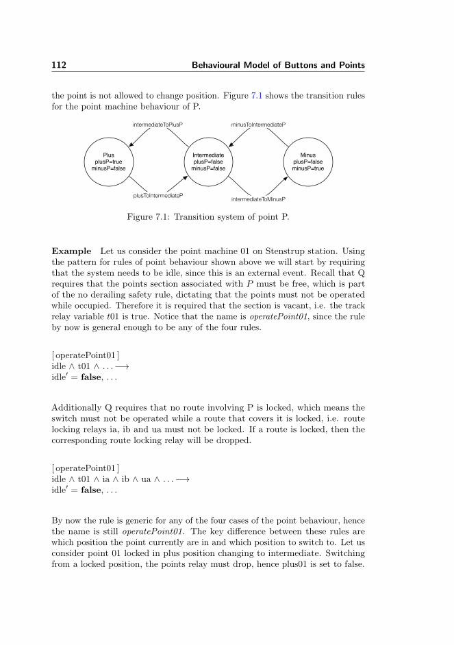
112 Behavioural Model of Buttons and Points
the point is not allowed to change position. Figure 7.1 shows the transition rulesfor the point machine behaviour of P.
IntermediateplusP=falseminusP=false
PlusplusP=trueminusP=false
MinusplusP=falseminusP=true
plusToIntermediateP
minusToIntermediateP
intermediateToMinusP
intermediateToPlusP
Figure 7.1: Transition system of point P.
Example Let us consider the point machine 01 on Stenstrup station. Usingthe pattern for rules of point behaviour shown above we will start by requiringthat the system needs to be idle, since this is an external event. Recall that Qrequires that the points section associated with P must be free, which is partof the no derailing safety rule, dictating that the points must not be operatedwhile occupied. Therefore it is required that the section is vacant, i.e. the trackrelay variable t01 is true. Notice that the name is operatePoint01, since the ruleby now is general enough to be any of the four rules.
[ operatePoint01 ]idle ∧ t01 ∧ . . .−→idle′ = false, . . .
Additionally Q requires that no route involving P is locked, which means theswitch must not be operated while a route that covers it is locked, i.e. routelocking relays ia, ib and ua must not be locked. If a route is locked, then thecorresponding route locking relay will be dropped.
[ operatePoint01 ]idle ∧ t01 ∧ ia ∧ ib ∧ ua ∧ . . .−→idle′ = false, . . .
By now the rule is generic for any of the four cases of the point behaviour, hencethe name is still operatePoint01. The key difference between these rules arewhich position the point currently are in and which position to switch to. Let usconsider point 01 locked in plus position changing to intermediate. Switchingfrom a locked position, the points relay must drop, hence plus01 is set to false.
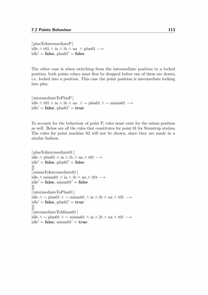
7.2 Points Behaviour 113
[ plusToIntermediateP ]idle ∧ t01 ∧ ia ∧ ib ∧ ua ∧ plus01 −→idle′ = false, plus01′ = false
The other case is when switching from the intermediate position to a lockedposition, both points relays must first be dropped before one of them are drawn,i.e. locked into a position. This case the point position is intermediate lockinginto plus.
[ intermediateToPlusP ]idle ∧ t01 ∧ ia ∧ ib ∧ ua ∧ ∼ plus01 ∧ ∼ minus01 −→idle′ = false, plus01′ = true
To account for the behaviour of point P, rules must exist for the minus positionas well. Below are all the rules that constitutes for point 01 for Stenstrup station.The rules for point machine 02 will not be shown, since they are made in asimilar fashion.
[ plusToIntermediate01 ]idle ∧ plus01 ∧ ia ∧ ib ∧ ua ∧ t01 −→idle′ = false, plus01′ = falsedebc[ minusToIntermediate01 ]idle ∧ minus01 ∧ ia ∧ ib ∧ ua ∧ t01 −→idle′ = false, minus01′ = falsedebc[ intermediateToPlus01 ]idle ∧ ∼ plus01 ∧ ∼ minus01 ∧ ia ∧ ib ∧ ua ∧ t01 −→idle′ = false, plus01′ = truedebc[ intermediateToMinus01 ]idle ∧ ∼ plus01 ∧ ∼ minus01 ∧ ia ∧ ib ∧ ua ∧ t01 −→idle′ = false, minus01′ = true

114 Behavioural Model of Buttons and Points
Chapter 8
Associations
This chapter will introduce two structures, both of which relates entities in thestation documentation to variables in the model. A human may guess that theboolean variable plus01 is the point detection relay for the plus position of apoints section, but it is a difficult task for a computer program.
It would be desirable to have a direct mapping between the physical elements ofthe station and the relays that observe them in terms of naming conventions.Unfortunately, this is not the case. In many cases one could derive the nameof the relays from the name of the element, but this is not generally true. Forexample, the point machine 02 is not located on track section 02 (happens to alinear), but is located on points section 03.
Section 8.1 introduces the object relay association, which is a collection ofassociations between physical objects (and train routes) and the variables thatmodels relays in the internal system.
Section 8.2 introduces train movement association, which is a collection ofassociations between the track sections and the variables introduced by themodel of train movements.

116 Associations
8.1 Object Relay Associations
Object relation associations are associations between physical objects (and trainroutes) and relay variable that models them, e.g. for Stenstrup, the track relayof track section 01 is modelled by the boolean variable t01.
typeObjectRelayAssociations ::
routeRelayAssoc : TrainRouteId →m VarIdtrackRelayAssoc : TrackId →m VarIdpointRelayAssoc : PointMachineId × Branch →m VarIdsignalRelayAssoc : SignalId × Lamp →m VarId
where we consider only the green and red lamp.
typeLamp == gr | re
8.1.1 Well-formedness of Object Relay Associations
The object relay association is well-formed if each of its components are well-formed and no relay variable is shared between the associations, e.g. the samerelay cannot be used both as a train route locking relay and as a point detectionrelay.
valueisWfObjectRelayAssociations : Diagram × TrainRouteTable ×
ObjectRelayAssociations → BoolisWfObjectRelayAssociations(d, trt, ora) ≡noRelayVariableOverlap(ora) ∧isWfRouteAssoc(trt, ora) ∧isWfTrackAssoc(d, ora) ∧isWfPointAssoc(d, ora) ∧isWfSignalAssoc(d, ora)
No relay variable is pointed to in more than one of the association maps.

8.1 Object Relay Associations 117
valuenoRelayVariableOverlap : ObjectRelayAssociations → BoolnoRelayVariableOverlap(ora) ≡
let routeVars = rng routeRelayAssoc(ora),trackVars = rng trackRelayAssoc(ora),pointVars = rng pointRelayAssoc(ora),signalVars = rng signalRelayAssoc(ora)
in routeVars ∩ trackVars = {} ∧routeVars ∩ pointVars = {} ∧routeVars ∩ signalVars = {} ∧trackVars ∩ pointVars = {} ∧trackVars ∩ signalVars = {} ∧pointVars ∩ signalVars = {}
end
8.1.1.1 Well-formedness of Route Associations
The train route association map is well-formed if the map has the same domainhas the train route table, i.e. all the train routes.
valueisWfRouteAssoc : TrainRouteTable ×
ObjectRelayAssociations → BoolisWfRouteAssoc(trt, ora) ≡
dom routeRelayAssoc(ora) = dom trt
8.1.1.2 Well-formedness of Track Associations
The track section association map is well-formed if the map has exactly all ofthe track sections of the station in its domain.
valueisWfTrackAssoc : Diagram × ObjectRelayAssociations → BoolisWfTrackAssoc(d, ora) ≡
let allTrackSections = allLinears(d) ∪ allPoints(d)in dom trackRelayAssoc(ora) = allTrackSectionsend

118 Associations
8.1.1.3 Well-formedness of Point Machine Associations
The point machine association map is well-formed if:
1. Every point machine on the station is part of the association and everypoint machine in the association exists on the station.
2. The same relay may not appear in the association twice.
valueisWfPointAssoc : Diagram × ObjectRelayAssociations → BoolisWfPointAssoc(d, ora) ≡
existingPointMachines(d, ora) ∧differentPointRelays(ora)
1. Existing Point Machines The point machines in the association mustexist on the station and vice versa.
valueexistingPointMachines : Diagram ×
ObjectRelayAssociations → BoolexistingPointMachines(d, ora) ≡
( ∀ (pmId, b) : PointMachineId × Branch •
(pmId, b) ∈ dom pointRelayAssoc(ora) ⇒pmId ∈ dom pointMachineTrack(d)
) ∧( ∀ pmId : PointMachineId •
pmId ∈ dom pointMachineTrack(d) ⇒( ∃ (pmId′, b) : PointMachineId × Branch •
(pmId′, b) ∈ dom pointRelayAssoc(ora) ∧pmId = pmId′ )
)
2. Each relay in the association, must only appear once The same relaymay not be used to lock different points or the same point in different positions.
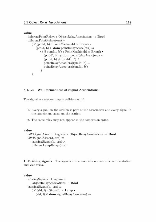
8.1 Object Relay Associations 119
valuedifferentPointRelays : ObjectRelayAssociations → BooldifferentPointRelays(ora) ≡
( ∀ (pmId, b) : PointMachineId × Branch •
(pmId, b) ∈ dom pointRelayAssoc(ora) ⇒∼( ∃ (pmId′, b′) : PointMachineId × Branch •
(pmId′, b′) ∈ dom pointRelayAssoc(ora) ∧(pmId, b) 6= (pmId′, b′) ∧pointRelayAssoc(ora)(pmId, b) =pointRelayAssoc(ora)(pmId′, b′)
))
8.1.1.4 Well-formedness of Signal Associations
The signal association map is well-formed if:
1. Every signal on the station is part of the association and every signal inthe association exists on the station.
2. The same relay may not appear in the association twice.
valueisWfSignalAssoc : Diagram × ObjectRelayAssociations → BoolisWfSignalAssoc(d, ora) ≡
existingSignals(d, ora) ∧differentLampRelays(ora)
1. Existing signals The signals in the association must exist on the stationand vice versa.
valueexistingSignals : Diagram ×
ObjectRelayAssociations → BoolexistingSignals(d, ora) ≡
( ∀ (sId, l) : SignalId × Lamp •
(sId, l) ∈ dom signalRelayAssoc(ora) ⇒

120 Associations
sId ∈ allSignals(d)) ∧( ∀ sId : SignalId •
sId ∈ allSignals(d) ⇒( ∃ (sId′, l) : SignalId × Lamp •
(sId′, l) ∈ dom signalRelayAssoc(ora) ∧sId = sId′ )
)
2. Each relay in the association, must only appear once The same relaymay not be used to control different lamps.
valuedifferentLampRelays : ObjectRelayAssociations → BooldifferentLampRelays(ora) ≡
( ∀ (sId, l) : SignalId × Lamp •
(sId, l) ∈ dom signalRelayAssoc(ora) ⇒∼( ∃ (sId′, l′) : SignalId × Lamp •
(sId′, l′) ∈ dom signalRelayAssoc(ora) ∧(sId, l) 6= (sId′, l′) ∧signalRelayAssoc(ora)(sId, l) =signalRelayAssoc(ora)(sId′, l′)
))
8.2 Train Movement Associations
Train movement associations is a collection of maps that associates track sectionsto the variables used in the model of train movements.
typeTrainMovementAssociations ::
connectionVars : (TrackId × TrackId) →m VarIdcounterVars : TrackId →m VarIddirectionFwdVars : TrackId →m VarIddirectionBwdVars : TrackId →m VarIddirections : (TrackId × TrackId) →m Direction
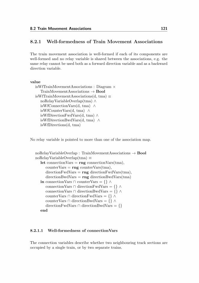
8.2 Train Movement Associations 121
8.2.1 Well-formedness of Train Movement Associations
The train movement association is well-formed if each of its components arewell-formed and no relay variable is shared between the associations, e.g. thesame relay cannot be used both as a forward direction variable and as a backwarddirection variable.
valueisWfTrainMovementAssociations : Diagram ×
TrainMovementAssociations → BoolisWfTrainMovementAssociations(d, tma) ≡
noRelayVariableOverlap(tma) ∧isWfConnectionVars(d, tma) ∧isWfCounterVars(d, tma) ∧isWfDirectionFwdVars(d, tma) ∧isWfDirectionBwdVars(d, tma) ∧isWfDirections(d, tma)
No relay variable is pointed to more than one of the association map.
noRelayVariableOverlap : TrainMovementAssociations → BoolnoRelayVariableOverlap(tma) ≡
let connectionVars = rng connectionVars(tma),counterVars = rng counterVars(tma),directionFwdVars = rng directionFwdVars(tma),directionBwdVars = rng directionBwdVars(tma)
in connectionVars ∩ counterVars = {} ∧connectionVars ∩ directionFwdVars = {} ∧connectionVars ∩ directionBwdVars = {} ∧counterVars ∩ directionFwdVars = {} ∧counterVars ∩ directionBwdVars = {} ∧directionFwdVars ∩ directionBwdVars = {}
end
8.2.1.1 Well-formedness of connectionVars
The connection variables describe whether two neighbouring track sections areoccupied by a single train, or by two separate trains.

122 Associations
The connection variables association is well-formed if
1. The pair of track sections in each key are neighbours.
2. Variables are not shared.
valueisWfConnectionVars : Diagram ×
TrainMovementAssociations → BoolisWfConnectionVars(d, tma) ≡
conVarsValidDomain(d, tma) ∧conVarsValidRange(connectionVars(tma))
1. Only neighbours can have a connection variable Only track sectionsthat are neighbours may have a connection variable.
valueconVarsValidDomain : Diagram ×
TrainMovementAssociations → BoolconVarsValidDomain(d, tma) ≡
(∀ (tId1, tId2) : (TrackId × TrackId) •
(tId1, tId2) ∈ dom connectionVars(tma) ⇒areNeighbours(tId1, tId2, d) )
2. No shared variables No two neighbour pair may share a connectionvariable.
valueconVarsValidRange : ((TrackId × TrackId) →m VarId) → BoolconVarsValidRange(connectionVars) ≡
(∀ key : (TrackId × TrackId) •
key ∈ dom connectionVars ⇒∼( ∃ key′ : (TrackId × TrackId) •
key′ ∈ dom connectionVars ∧key 6= key′ ∧connectionVars(key) =connectionVars(key′) )
)
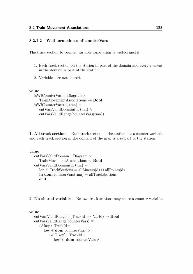
8.2 Train Movement Associations 123
8.2.1.2 Well-formedness of counterVars
The track section to counter variable association is well-formed if:
1. Each track section on the station in part of the domain and every elementin the domain is part of the station.
2. Variables are not shared.
valueisWfCounterVars : Diagram ×
TrainMovementAssociations → BoolisWfCounterVars(d, tma) ≡
cntVarsValidDomain(d, tma) ∧cntVarsValidRange(counterVars(tma))
1. All track sections Each track section on the station has a counter variableand each track section in the domain of the map is also part of the station.
valuecntVarsValidDomain : Diagram ×
TrainMovementAssociations → BoolcntVarsValidDomain(d, tma) ≡
let allTrackSections = allLinears(d) ∪ allPoints(d)in dom counterVars(tma) = allTrackSectionsend
2. No shared variables No two track sections may share a counter variable.
valuecntVarsValidRange : (TrackId →m VarId) → BoolcntVarsValidRange(counterVars) ≡
(∀ key : TrackId •
key ∈ dom counterVars ⇒∼( ∃ key′ : TrackId •
key′ ∈ dom counterVars ∧
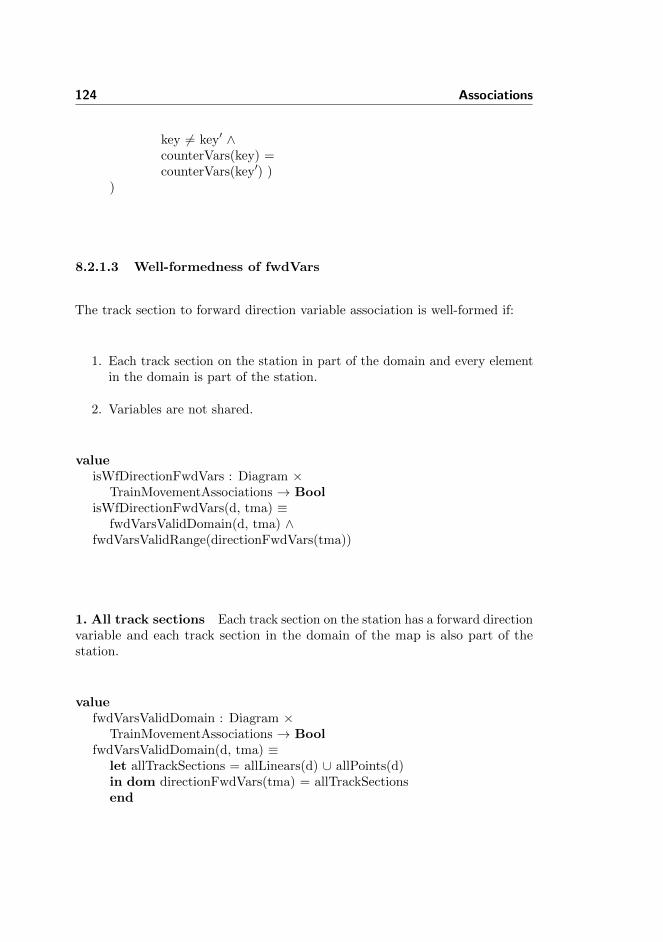
124 Associations
key 6= key′ ∧counterVars(key) =counterVars(key′) )
)
8.2.1.3 Well-formedness of fwdVars
The track section to forward direction variable association is well-formed if:
1. Each track section on the station in part of the domain and every elementin the domain is part of the station.
2. Variables are not shared.
valueisWfDirectionFwdVars : Diagram ×
TrainMovementAssociations → BoolisWfDirectionFwdVars(d, tma) ≡
fwdVarsValidDomain(d, tma) ∧fwdVarsValidRange(directionFwdVars(tma))
1. All track sections Each track section on the station has a forward directionvariable and each track section in the domain of the map is also part of thestation.
valuefwdVarsValidDomain : Diagram ×
TrainMovementAssociations → BoolfwdVarsValidDomain(d, tma) ≡
let allTrackSections = allLinears(d) ∪ allPoints(d)in dom directionFwdVars(tma) = allTrackSectionsend
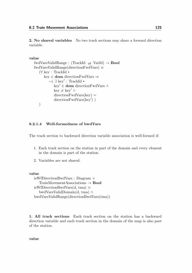
8.2 Train Movement Associations 125
2. No shared variables No two track sections may share a forward directionvariable.
valuefwdVarsValidRange : (TrackId →m VarId) → BoolfwdVarsValidRange(directionFwdVars) ≡
(∀ key : TrackId •
key ∈ dom directionFwdVars ⇒∼( ∃ key′ : TrackId •
key′ ∈ dom directionFwdVars ∧key 6= key′ ∧directionFwdVars(key) =directionFwdVars(key′) )
)
8.2.1.4 Well-formedness of bwdVars
The track section to backward direction variable association is well-formed if:
1. Each track section on the station in part of the domain and every elementin the domain is part of the station.
2. Variables are not shared.
valueisWfDirectionBwdVars : Diagram ×
TrainMovementAssociations → BoolisWfDirectionBwdVars(d, tma) ≡
bwdVarsValidDomain(d, tma) ∧bwdVarsValidRange(directionBwdVars(tma))
1. All track sections Each track section on the station has a backwarddirection variable and each track section in the domain of the map is also partof the station.
value

126 Associations
bwdVarsValidDomain : Diagram ×TrainMovementAssociations → Bool
bwdVarsValidDomain(d, tma) ≡let allTrackSections = allLinears(d) ∪ allPoints(d)in dom directionBwdVars(tma) = allTrackSectionsend
2. No shared variables No two track sections may share a backward directionvariable.
valuebwdVarsValidRange : (TrackId →m VarId) → BoolbwdVarsValidRange(directionBwdVars) ≡
(∀ key : TrackId •
key ∈ dom directionBwdVars ⇒∼( ∃ key′ : TrackId •
key′ ∈ dom directionBwdVars ∧key 6= key′ ∧directionBwdVars(key) =directionBwdVars(key′) )
)
8.2.1.5 Well-formedness of directions
The directions association is well-formed if
1. The pair of track sections in each key are neighbours.
2. Each neighbour pair have both and forward and a backward direction.
valueisWfDirections : Diagram ×
TrainMovementAssociations → BoolisWfDirections(d, tma) ≡
directionsValidDomain(d, tma) ∧bothDirections(directions(tma))

8.2 Train Movement Associations 127
1. Track section pairs are neighbours Each track section pair in the domainare neighbours.
valuedirectionsValidDomain : Diagram ×
TrainMovementAssociations → BooldirectionsValidDomain(d, tma) ≡
(∀ (tId1, tId2) : (TrackId × TrackId) •
(tId1, tId2) ∈ dom directions(tma) ⇒areNeighbours(tId1, tId2, d) )
2. Both directions present Each neighbour pair has both an associatedforward and backward variable.
valuebothDirections :
((TrackId × TrackId) →m Direction) → BoolbothDirections(directions) ≡
( ∀ (tId1, tId2) : (TrackId × TrackId) •
(tId1, tId2) ∈ dom directions ⇒( ∃ (tId1′, tId2′) : (TrackId × TrackId) •
(tId1′, tId2′) ∈ dom directions ∧tId1 = tId2′ ∧ tId2 = tId1′ ∧directions((tId1, tId2)) 6=directions((tId1′, tId2′))
))

128 Associations

Chapter 9
Inter-Model Consistency
The following chapter introduces conditions for the inter-model consistency thatare requirements to ensure that the interaction between the model of trainmovement and the relay system model behaves as expected.
The requirements are first described informally in italics. Then the requirementsare written formally as LTL assertions. Finally each formulae is used to write aconcrete example for Stenstrup station.
The model of train movement in chapter 6 introduced variables used to modelthe behaviour of the external environment. This chapter uses these variables topresent formulae to ensure the inter-model consistency.
The presented patterns in this chapter are useful when we in chapter 11 introducethe Generator, that are using these formulae to generate the assertions.
The formal properties are written as formulas in linear temporal logic (LTL).
Section 9.1 will introduce variables used in the LTL expressions discussed in thischapter and chapter 10.
The rest of the sections within this chapter will introduce the inter-modelconsistency conditions.

130 Inter-Model Consistency
9.1 Variables
The model of train movement simulates the movement on the track sections. Wewant to ensure that changes to the state space of the model of train movementis reflected in the model of the interlocking system, i.e. when the model of trainmovement claims a train occupy a given track section, the interlocking systemshould detect that track section as occupied and vice versa.
The variables introduced below should be interpreted as place holders for theactual relays in the internal system model. Their values are boolean, meaning itconsists by either true or false. TrackCounter is, on the other hand, a variablethat contains unsigned natural numbers.
Variables for the relay system model:
TrackRelayT False when track section T is occupied by a train.
PlusRelayP True when points section P is positioned in plus.False when P is not positioned in plus configuration.
MinusRelayP True when points section P is positioned in minus.False when P is not positioned in minus configuration.
Note when PlusRelayP and MinusRelayP for points section P is both falsethe points position configuration is in the intermediate state. Refer to section7.2 on point behaviour.
Variables introduced in the model of train movement:
TrackCounterT Counts the number of trains on a track section T .
ForwardT True if a train is moving forward on track sectionT . False when no train is moving forward on tracksection T .
BackwardT True if a train is moving backward on track T . Falsewhen no train is moving backward on track sectionT .
ConnectionT1T2True if a train is intersecting track section T1 andtrack section T2.

9.2 Track Occupation 131
9.2 Track Occupation
A track section can either be occupied or vacant. The model of the internalinterlocking system uses this information to set the relay as a boolean value,where the train movement model uses counters to enable more trains on atrack section. The agreement among the two models is that the model of trainmovement knows its own location and this location must be detected by theinternal system.
To ensure that the relays and the counters are interacting as expected tworequirements are formed.
If a track relay TrackRelayT , for track T is dropped, then the associated counteris greater than zero.∧
T∈AllTracks2¬TrackRelayT ⇒ TrackCounterT > 0
If a track counter TrackCounterT associated to track T is greater than zero,then track relay TrackRelayT is dropped∧
T∈AllTracks2TrackCounterT > 0⇒ ¬TrackRelayT
These two requirements ensure that if and only if there is detected a train on trackT the TrackCounterT is greater than zero and the track relay TrackRelayT isdropped.
Example The expression below requires that if track relay a12 is dropped,then track counter cnt A12 must be greater than zero.
2¬a12⇒ cnt A12 > 0
And if the track counter cnt A12 is greater than zero, then track relay a12 mustbe dropped.
2cnt A12 > 0⇒ ¬a12
9.3 Track Free
Similar to occupying tracks, requirements of freeing tracks must be formulated.Thus, when the model of train movement dictates there is no train on a certain
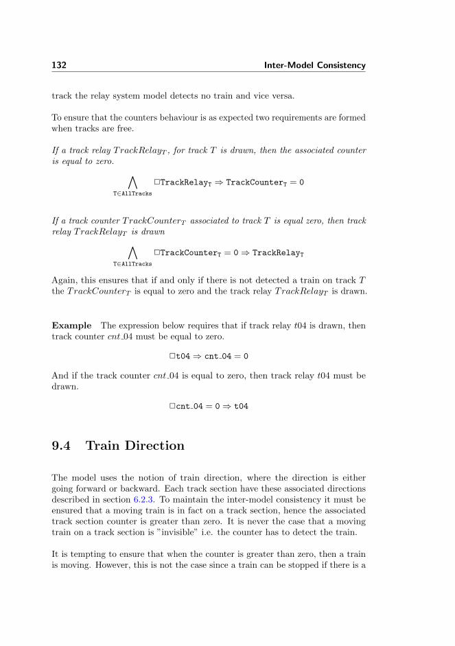
132 Inter-Model Consistency
track the relay system model detects no train and vice versa.
To ensure that the counters behaviour is as expected two requirements are formedwhen tracks are free.
If a track relay TrackRelayT , for track T is drawn, then the associated counteris equal to zero. ∧
T∈AllTracks2TrackRelayT ⇒ TrackCounterT = 0
If a track counter TrackCounterT associated to track T is equal zero, then trackrelay TrackRelayT is drawn∧
T∈AllTracks2TrackCounterT = 0⇒ TrackRelayT
Again, this ensures that if and only if there is not detected a train on track Tthe TrackCounterT is equal to zero and the track relay TrackRelayT is drawn.
Example The expression below requires that if track relay t04 is drawn, thentrack counter cnt 04 must be equal to zero.
2t04⇒ cnt 04 = 0
And if the track counter cnt 04 is equal to zero, then track relay t04 must bedrawn.
2cnt 04 = 0⇒ t04
9.4 Train Direction
The model uses the notion of train direction, where the direction is eithergoing forward or backward. Each track section have these associated directionsdescribed in section 6.2.3. To maintain the inter-model consistency it must beensured that a moving train is in fact on a track section, hence the associatedtrack section counter is greater than zero. It is never the case that a movingtrain on a track section is ”invisible” i.e. the counter has to detect the train.
It is tempting to ensure that when the counter is greater than zero, then a trainis moving. However, this is not the case since a train can be stopped if there is a

9.5 Points Configuration 133
signal with stop aspect. For same reason, it can not be concluded that a train ismoving if a track relay is dropped.
Another tempting requirement is that the direction cannot be forward andbackward at the same time. However, physically the model is able to have twotrains on a track section going with an opposite direction.
If a moving train is on track T , then the associated counter for track T is greaterthan zero. ∧
T∈AllTracks2BackwardT ∨ ForwardT ⇒ TrackCounterT > 0
Example The expression below requires that if a moving train is on tracksection 03, then track counter cnt 03 must be greater than zero.
2bwd 03 ∨ fwd 03⇒ cnt 03 > 0
9.5 Points Configuration
The physical limitation of a points section is the position configuration can bein either plus, minus or intermediate. Where intermediate simulates a state thatis neither plus nor minus. Thus somewhere in between plus and minus.
This physical requirement must be ensured in the model. The points relaycontrols the point machines that is the mechanical arm to switch between plusand minus. Assuming that the point machine always obeys the points relayfollowing requirement is stated.
For all points sections P it is never the case they are plus and minus.∧P∈AllPoints
2Idle⇒ ¬(PlusRelayP ∧ MinusRelayP)
Note by using this expression the intermediate state is also accepted, which iswhen both PlusP and MinusP are false.
Example The expression below requires that points section 01, is in eitherplus, minus or intermediate state.
2Idle⇒ ¬(plus01 ∧ minus01)

134 Inter-Model Consistency
9.6 Train Connection
The model uses the notion of train connection, where the connection is a booleanvalue that for each neighbour pair of track sections is a connection variable. Thisconnection variable indicates whether a train intersects (overlaps) any tracksections.
If a train has a connection that intersects track T1 and T2, then the associatedtrack counter for track T1 and T2 are greater than zero.∧
(T1,T2)∈allNeighbours
2ConnectionT1T2 ⇒
TrackCounterT1 > 0 ∧ TrackCounterT2 > 0
Note that it cannot be concluded that if TrackCounterT1 and TrackCounterT2
are greater than zero, then there is a connection. This is simply because twodistinct trains can occupy each of these track sections.
Example The expression below requires that if a train is on track section 02and 03, then track counter cnt 02 and cnt 03 must be greater than zero.
2con 02 03⇒ cnt 02 > 0 ∧ cnt 03 > 0

Chapter 10
Safety Properties
The following chapter describes the safety requirements that ensure safe trainoperation, which first and foremost includes the safety properties for no collisionand no derailing introduced in section 2.4. Additional safety properties derivedfrom the train route table for a given station will be described.
The requirements are first described informally in italics. Then the requirementsare written formally, but abstract. Finally the abstract formulae are used towrite a concrete example for Stenstrup station.
Stenstrup station is secured by a relay based interlocking system. For theremainder of this document, it is assumed that there exists a boolean variablefor each relay in the interlocking system, which mirrors the relays state, i.e. istrue when the relay is drawn.
The formal properties are written as formulas in linear temporal logic (LTL).
10.1 Variables
We introduce the following variables in addition to those from section 9.1:

136 Safety Properties
LockingRelayx False when train route x is locked. Occasionallyroutes share the same locking relay and the specificroutes are then differentiated by the position ofthe points on the route (PointsLockedx).
PointsLockedx True when the points in route x are locked in theposition dictated by the train route table for thatroute x.
RouteLockedx True when train route x is locked and the pointsof the route are locked in the position required forthat route, i.e.
RouteLockedx = ¬LockingRelayx∧PointsLockedx
TrackFreex True if every track section in route x is unoccupied,as specified in the train route table for route x.
SignalsSetx True if every signal on route x is set to the aspectrequired by the train route table for route x.
ProceedAspectS True when signal S signals proceed.
StopAspectS True when signal S signals stop.
SignalReleaseIsolationx False when signal release isolation on route x isoccupied.
PositionRelayT,P True when the points section P is locked to thebranch, that the neighbouring track section T isconnected to.
Indlx True when the first condition (Indl) of the trainroute release in the train route table for route xholds.
Oplx True when the second condition (Opl) of the trainroute release in the train route table for route xholds.
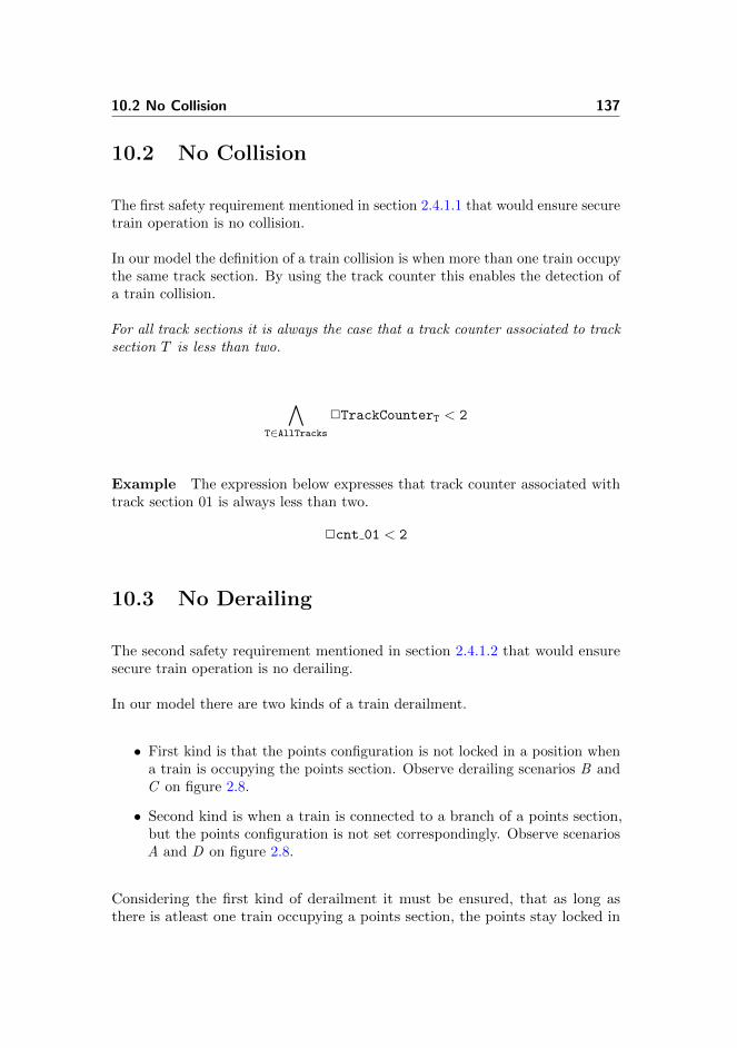
10.2 No Collision 137
10.2 No Collision
The first safety requirement mentioned in section 2.4.1.1 that would ensure securetrain operation is no collision.
In our model the definition of a train collision is when more than one train occupythe same track section. By using the track counter this enables the detection ofa train collision.
For all track sections it is always the case that a track counter associated to tracksection T is less than two.
∧T∈AllTracks
2TrackCounterT < 2
Example The expression below expresses that track counter associated withtrack section 01 is always less than two.
2cnt 01 < 2
10.3 No Derailing
The second safety requirement mentioned in section 2.4.1.2 that would ensuresecure train operation is no derailing.
In our model there are two kinds of a train derailment.
• First kind is that the points configuration is not locked in a position whena train is occupying the points section. Observe derailing scenarios B andC on figure 2.8.
• Second kind is when a train is connected to a branch of a points section,but the points configuration is not set correspondingly. Observe scenariosA and D on figure 2.8.
Considering the first kind of derailment it must be ensured, that as long asthere is atleast one train occupying a points section, the points stay locked in
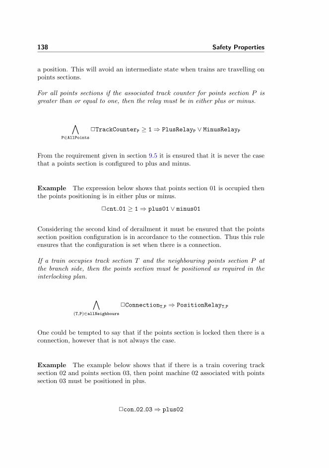
138 Safety Properties
a position. This will avoid an intermediate state when trains are travelling onpoints sections.
For all points sections if the associated track counter for points section P isgreater than or equal to one, then the relay must be in either plus or minus.
∧P∈AllPoints
2TrackCounterP ≥ 1⇒ PlusRelayP ∨ MinusRelayP
From the requirement given in section 9.5 it is ensured that it is never the casethat a points section is configured to plus and minus.
Example The expression below shows that points section 01 is occupied thenthe points positioning is in either plus or minus.
2cnt 01 ≥ 1⇒ plus01 ∨ minus01
Considering the second kind of derailment it must be ensured that the pointssection position configuration is in accordance to the connection. Thus this ruleensures that the configuration is set when there is a connection.
If a train occupies track section T and the neighbouring points section P atthe branch side, then the points section must be positioned as required in theinterlocking plan.
∧(T,P)∈allNeighbours
2ConnectionT,P ⇒ PositionRelayT,P
One could be tempted to say that if the points section is locked then there is aconnection, however that is not always the case.
Example The example below shows that if there is a train covering tracksection 02 and points section 03, then point machine 02 associated with pointssection 03 must be positioned in plus.
2con 02 03⇒ plus02
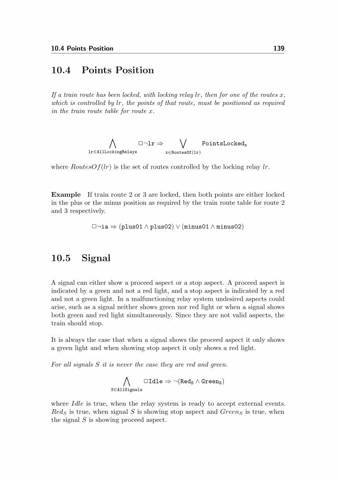
10.4 Points Position 139
10.4 Points Position
If a train route has been locked, with locking relay lr, then for one of the routes x,which is controlled by lr, the points of that route, must be positioned as requiredin the train route table for route x.
∧lr∈AllLockingRelays
2¬lr⇒∨
x∈RoutesOf(lr)
PointsLockedx
where RoutesOf(lr) is the set of routes controlled by the locking relay lr.
Example If train route 2 or 3 are locked, then both points are either lockedin the plus or the minus position as required by the train route table for route 2and 3 respectively.
2¬ia⇒ (plus01 ∧ plus02) ∨ (minus01 ∧ minus02)
10.5 Signal
A signal can either show a proceed aspect or a stop aspect. A proceed aspect isindicated by a green and not a red light, and a stop aspect is indicated by a redand not a green light. In a malfunctioning relay system undesired aspects couldarise, such as a signal neither shows green nor red light or when a signal showsboth green and red light simultaneously. Since they are not valid aspects, thetrain should stop.
It is always the case that when a signal shows the proceed aspect it only showsa green light and when showing stop aspect it only shows a red light.
For all signals S it is never the case they are red and green.∧S∈AllSignals
2Idle⇒ ¬(RedS ∧ GreenS)
where Idle is true, when the relay system is ready to accept external events.RedS is true, when signal S is showing stop aspect and GreenS is true, whenthe signal S is showing proceed aspect.
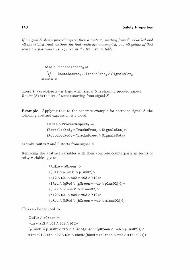
140 Safety Properties
If a signal S shows proceed aspect, then a route x, starting from S, is locked andall the related track sections for that route are unoccupied, and all points of thatroute are positioned as required in the train route table.
2Idle ∧ ProceedAspectS ⇒∨x∈Routes(S)
RouteLockedx ∧ TracksFreex ∧ SignalsSetx
where ProceedAspectS is true, when signal S is showing proceed aspect.Routes(S) is the set of routes starting from signal S.
Example Applying this to the concrete example for entrance signal A thefollowing abstract expression is yielded:
2Idle ∧ ProceedAspectA ⇒(RouteLocked2 ∧ TracksFree2 ∧ SignalsSet2)∨(RouteLocked3 ∧ TracksFree3 ∧ SignalsSet3)
as train routes 2 and 3 starts from signal A.
Replacing the abstract variables with their concrete counterparts in terms ofrelay variables gives:
2idle ∧ aGreen⇒((¬ia ∧ plus01 ∧ plus02)∧(a12 ∧ t01 ∧ t02 ∧ t03 ∧ b12)∧(fRed ∧ (gRed ∨ (gGreen ∧ ¬ub ∧ plus02))))∨((¬ia ∧ minus01 ∧ minus02)∧(a12 ∧ t01 ∧ t04 ∧ t03 ∧ b12)∧(eRed ∧ (hRed ∨ (hGreen ∧ ¬ub ∧ minus02))))
This can be reduced to:
2idle ∧ aGreen⇒¬ia ∧ a12 ∧ t01 ∧ t03 ∧ b12∧(plus01 ∧ plus02 ∧ t02 ∧ fRed∧(gRed ∨ (gGreen ∧ ¬ub ∧ plus02)))∨minus01 ∧ minus02 ∧ t04 ∧ eRed∧(hRed ∨ (hGreen ∧ ¬ub ∧ minus02)))

10.6 Signal Release 141
The expression above shows that if entrance signal A is showing proceed aspect,then train route 2 or 3 is locked and their common track sections are unoccupied.Depending on whether route 2 or 3 is locked the points are set correspondingly,as described in section 10.4, and the track section, t02 or t04, for that routeis unoccupied, required in the train route table. Signals E and F are showingstop aspect depending on the point positioning. Finally, signals G and H areshowing stop aspect unless an exit route has already been locked1. For route 2this means that G shows stop unless route 9 is also locked in which case G mayshow a drive aspect. Similarly, for route 3 this means that H shows stop unlessroute 10 is also locked in which case H may show a proceed aspect2.
10.6 Signal Release
If the track section SignalReleaseIsolationx, specified in the signal release fieldfor route x in the train route table, is occupied, then the signal S in the signalrelease field must show stop aspect.
2Idle ∧ ¬SignalReleaseIsolationx ⇒ StopAspectx
If signal release isolation on route x is occupied the signal release signal on routex must show stop aspect.
Example The expression below requires that if track section a12 is occupiedby an object, then signal A must show a stop aspect and no longer show a driveaspect.
2idle ∧ ¬a12⇒ aRed
Recall from section 10.5 that a signal may not show a red and a green lightsimultaneously.
10.7 Conflicting Routes
If a train route x is locked, then a conflicting route y must not be locked.
2RouteLockedx ⇒∧
y∈ConflictingRoutes(x)
¬RouteLockedy
1Viser ”kør” hvis der i forvejen er stillet udkørsel2Note that these routes are not conflicting routes.

142 Safety Properties
Example If route 2 is locked the following abstract expression is given:
2RouteLocked2 ⇒¬RouteLocked3∧¬RouteLocked5∧¬RouteLocked6∧¬RouteLocked7∧¬RouteLocked8∧¬RouteLocked10
Applying this to the concrete example for route 2 the following is given:
2¬ia ∧ plus01 ∧ plus02⇒¬(¬ia ∧ minus01 ∧ minus02)∧¬(¬ib ∧ plus01 ∧ plus02)∧¬(¬ib ∧ minus01 ∧ minus02)∧¬(¬ua ∧ plus01)∧¬(¬ua ∧ minus01)∧¬(¬ub ∧ minus02)
The expression above requires that if train route 2 is locked, then train routes 3,5, 6, 7, 8 and 10 are not locked.
10.8 Train Route Release
In order to release a locked train route there must occur a release sequence.Recall from section 2.6.2.7, that the release sequence involves a train to occupyand leave track sections in a certain order.
There are two properties for train route release. One is a safety property, theother a liveliness property.
Safety If a train route has been locked, then the route is not released until afterthe release sequence (Indl. → Opl.)
Liveliness After the release sequence, the route is eventually released3
3Not considered
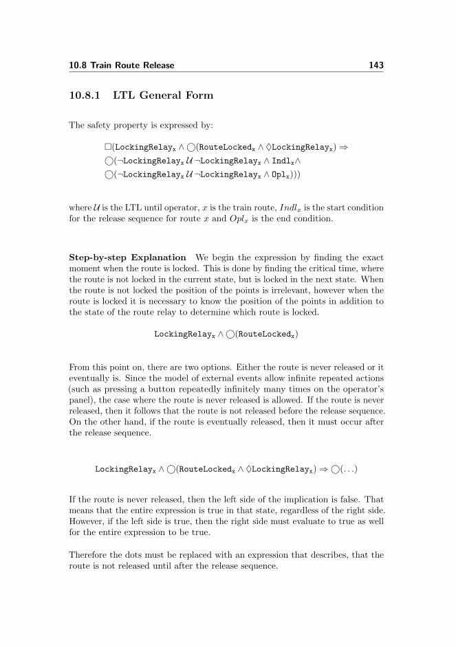
10.8 Train Route Release 143
10.8.1 LTL General Form
The safety property is expressed by:
�(LockingRelayx ∧©(RouteLockedx ∧ ♦LockingRelayx)⇒©(¬LockingRelayx U ¬LockingRelayx ∧ Indlx∧©(¬LockingRelayx U ¬LockingRelayx ∧ Oplx)))
where U is the LTL until operator, x is the train route, Indlx is the start conditionfor the release sequence for route x and Oplx is the end condition.
Step-by-step Explanation We begin the expression by finding the exactmoment when the route is locked. This is done by finding the critical time, wherethe route is not locked in the current state, but is locked in the next state. Whenthe route is not locked the position of the points is irrelevant, however when theroute is locked it is necessary to know the position of the points in addition tothe state of the route relay to determine which route is locked.
LockingRelayx ∧©(RouteLockedx)
From this point on, there are two options. Either the route is never released or iteventually is. Since the model of external events allow infinite repeated actions(such as pressing a button repeatedly infinitely many times on the operator’spanel), the case where the route is never released is allowed. If the route is neverreleased, then it follows that the route is not released before the release sequence.On the other hand, if the route is eventually released, then it must occur afterthe release sequence.
LockingRelayx ∧©(RouteLockedx ∧ ♦LockingRelayx)⇒©(. . .)
If the route is never released, then the left side of the implication is false. Thatmeans that the entire expression is true in that state, regardless of the right side.However, if the left side is true, then the right side must evaluate to true as wellfor the entire expression to be true.
Therefore the dots must be replaced with an expression that describes, that theroute is not released until after the release sequence.

144 Safety Properties
The route must be locked until (and including) the time of the initiation (Indl)of the release sequence.
¬LockingRelayx U ¬LockingRelayx ∧ Indlx
And once the initiation (Indl) is reached, we may still not release until the lastcondition Opl, which completes the sequence:
¬LockingRelayx U ¬LockingRelayx ∧ Indlx∧©(¬LockingRelayx U ¬LockingRelayx ∧ Oplx)
The formula is then completed by combining the two fragments and ensuringthat it holds for all states:
�(LockingRelayx ∧©(RouteLockedx ∧ ♦LockingRelayx)⇒©(¬LockingRelayx U ¬LockingRelayx ∧ Indlx∧©(¬LockingRelayx U ¬LockingRelayx ∧ Oplx)))
Example The following is a concrete example for train route 2 of StenstrupStation.
�(ia ∧©(¬ia ∧ plus01 ∧ plus02 ∧ ♦ia)⇒©(¬ia U ¬ia ∧ ¬t01 ∧ t02∧©(¬ia U ¬ia ∧ ¬t02 ∧ t01)))
where plus01, plus02 are true when points 01 and 02 are locked in the plusposition and ia is false when route 2 or 3 is locked.
Notice that even though some routes share the same locking relay, it is onlyneeded to check the points position, when the route is established, as the pointsare not allowed to be changed when a route is locked.
Chapter 11
Generator
Our generator takes the data model of the interlocking plan discussed in section4.1 and transforms it into a transition system containing a state space, transitionrules of the external events, and assertions (section 4.4). The generated transitionsystem can then be combined with the transition system of the internal eventsto obtain the complete system for verification.
This chapter will describe the flow of the generator, the required input of thegenerator, how the generator is creating the output and finally how the outputis then unparsed to RSL-SAL.
Section 11.2 shows the sub-generator that facilitates the generation of the statespace.
Section 11.3 shows the sub-generator that facilitates the generation of the trans-ition rules of the external behaviour.
Section 11.4 shows the sub-generator that facilitates the generation of the safetyproperties and the inter-model consistency assertions.
Section 11.5 shows how the output is generated by using an unparser.

146 Generator
11.1 Overview
The generator requires as input the interlocking plan that contains a station layoutdiagram and a train route table, which chapter 4 showed the type definitions of.Additionally, the associations are needed for the generator to map the names fromthe station elements with the relay system. The generator outputs a transitionsystem, which contains a state space, transition rules and assertions. Figure 11.1illustrates this simplified partitioning.
The specific input and output will be shown in the study case of Stenstrup inchapter 13.
OutputInput
Station Layout Diagram
Object Relay Associations
Generator
Transition System
Transition Rules
State Space
Train Route Table
Interlocking Plan
Assertions
Figure 11.1: Overview of the generator with the required input and generatedoutput.
An overview of the application flow is illustrated on figure 11.2. The file Stenstrup,specifically made for the Stenstrup station, instantiates StationLayout andObjectRelayAssociations and invokes the Generator. Within the generatorsubclasses facilitates the generation of state space, transition rules and assertions.
The State Generator creates and initialises the state space of the transition sys-tem (contained in the type TrainMovementAssociations). Transition Generatorfacilitates the creation of the transition rules of the external events and the Asser-tion Generator facilitates the creation of assertions containing safety propertiesand inter-model consistency conditions. The output from each generator arethen stored in a transition system, where the unparser prints it in a form thatRSL-SAL accepts.
The generate function, located in the Generator.rsl file, constructs a transitionsystem by requiring an interlocking plan, object relay associations used to mapthe station objects with the relays, the set of button identifiers1, and finally a
1Recall from section 7.1 that button identifiers cannot be extracted from the interlocking

11.2 State Generator 147
StateGenerator AssertionGeneratorObjectRelayAssociations
Generator
InterlockingPlan
StationLayout TrainMovementAssociationsTrainRouteTable
TransitionGenerator
TransitionSystem
Types
Unparser
Stenstrup
InstantiatesInstantiates
Invokes
Invokes Invokes Invokes
Output
Contains Contains Instantiates
Figure 11.2: Structure of the implementation.
text string to name the transition system. Each sub-generator is then invokedto create the transition system.
valuegenerate : Text × ObjectRelayAssociations ×
InterlockingPlan × Text-set → TransitionSystemgenerate(name, ora, ip, buttonIds) ≡
let sld = sld(ip),tma = genTrainMovementAssociations(sld)
in mk TransitionSystem(name,generateStateSpace(ip, tma),generateTransitionSystem(ora, ip, tma, buttonIds),generateAssertions(ora, ip, tma))
endpre isWfInterlockingPlan(ip) ∧
isWfObjectRelayAssociations(ora, ip)
11.2 State Generator
According to our model of train movement, the counter, connection, and directionvariables are to be generated.
All of this is stored in a TrainMovementAssociation value and is created by
plan nor can they be derived.

148 Generator
functions defined in StateGenerator.rsl, which can be found in appendixsection E.3.3 and E.2.4, respectively.
typeTrainMovementAssociations ::connectionVars : (TrackId × TrackId) →m VarIdcounterVars : TrackId →m VarIddirectionFwdVars : TrackId →m VarIddirectionBwdVars : TrackId →m VarIddirections : (TrackId × TrackId) →m Direction
where direction is
typeDirection == fwd | bwd
The generated TrainMovementAssociations are then used as input to the stategenerator to generate all the variables by calling the function generateStateSpace.The preconditions requires that the interlocking plan and the train movementassociations are well-formed.
valuegenerateStateSpace : InterlockingPlan ×
TrainMovementAssociations → Var-setgenerateStateSpace(ip, tma) ≡
genBoolVars(rng connectionVars(tma)) ∪genNatVars(rng counterVars(tma)) ∪genBoolVars(rng directionFwdVars(tma)) ∪genBoolVars(rng directionBwdVars(tma))
pre isWfInterlockingPlan(ip) ∧isWfTrainMovementAssociations(sld(ip), tma)
In the following sections the three types of variables will be introduced.
11.2.1 Counter Variables
Every track section has a counter which keeps track of how many trains currentlyoccupy the section. Therefore the state generator recursively goes through every

11.2 State Generator 149
track section (except for line) and creates a name of the counter variable for it.The name is created by prefixing “cnt ” to the name of the track section.
valuegenCntVars : TrackId-set × Diagram → TrackId →m VarIdgenCntVars(ids, d) ≡
if ids = {} then [ ] elselet id = hd ids, ids′ = ids \ {id}
in if isLine(id, d) then [ ]else genCntVar(id)end ∪ genCntVars(ids′, d)
endend,
genCntVar : TrackId → TrackId →m VarIdgenCntVar(id) ≡ [ id 7→ ′′cnt_′′ id ]
It is then stored in a map, where the id of the track section is used as key.
valuecounterVars : TrackId →m VarId
This creates an association between a track section and the variable.
11.2.2 Connection Variables
Every track section has a connection variable for each of its neighbours. Therefore,the generator uses the neighbour relation, introduced in section 4.2.4, as it onlycontains one entry for each pair of neighbours. As with the counter variablesthe line section is disregard. The name is generated by prefixing “con ” to theidentifiers of the neighbouring track section, which have been concatenated withan underscore in between.
valuegenConVars : (TrackId × TrackId)-set × Diagram →
(TrackId × TrackId) →m VarIdgenConVars(nbs, d) ≡
if nbs = {} then [ ] else
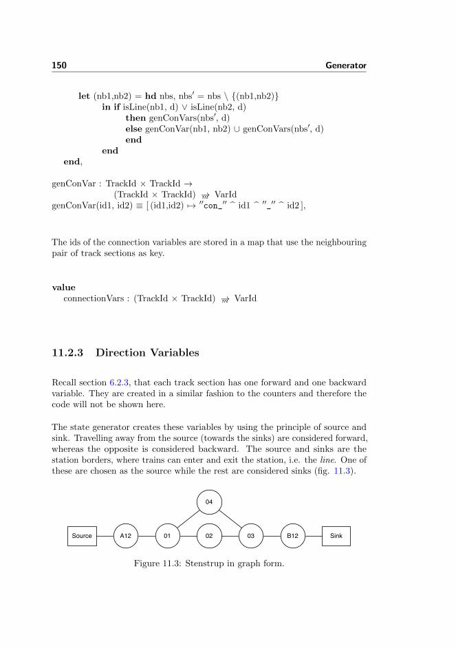
150 Generator
let (nb1,nb2) = hd nbs, nbs′ = nbs \ {(nb1,nb2)}in if isLine(nb1, d) ∨ isLine(nb2, d)
then genConVars(nbs′, d)else genConVar(nb1, nb2) ∪ genConVars(nbs′, d)end
endend,
genConVar : TrackId × TrackId →(TrackId × TrackId) →m VarId
genConVar(id1, id2) ≡ [ (id1,id2) 7→ ′′con_′′ id1 ′′_′′ id2 ],
The ids of the connection variables are stored in a map that use the neighbouringpair of track sections as key.
valueconnectionVars : (TrackId × TrackId) →m VarId
11.2.3 Direction Variables
Recall section 6.2.3, that each track section has one forward and one backwardvariable. They are created in a similar fashion to the counters and therefore thecode will not be shown here.
The state generator creates these variables by using the principle of source andsink. Travelling away from the source (towards the sinks) are considered forward,whereas the opposite is considered backward. The source and sinks are thestation borders, where trains can enter and exit the station, i.e. the line. One ofthese are chosen as the source while the rest are considered sinks (fig. 11.3).
A12 01 02
04
03 B12Source Sink
Figure 11.3: Stenstrup in graph form.

11.2 State Generator 151
It is noteworthy that the model of the station only has a single line section (fig.11.4). Therefore it is necessary to consider it a special case. Otherwise it wouldact only as source and never as sink.
A12 01 02
04
03 B12
Line
Figure 11.4: Stenstrup in graph form.
The algorithm assigns the directions in the following manner. First all theneighbours of line are collected. Lets call them nb1, . . . , nbn where n is thenumber of neighbours to line and n ≥ 1. Then the edge from line to nb1 is giventhe direction forward and the edge from nb1 to line is marked as backward.
For the remainder, the backward direction will always be the opposite directionof the forward and will therefore not be mentioned again. For the remainingneighbours of line, the direction from the neighbour to line is forward. In thisway a single source with possible multiple sinks have been created (fig. 11.5).
A12 01 02
04
03 B12
Lineforward
backward
forward
backward
nb1 nb2
Figure 11.5: Stenstrup in graph form.
The rest of the network is then traversed from the neighbours of the source.Visited notes are marked so that they are not visited again. In this mannerdirections are given to the edges of the entire network, except for sources andsinks, which have already been visited in the first step. See figure 11.6 for astep-by-step run-though of the algorithm.
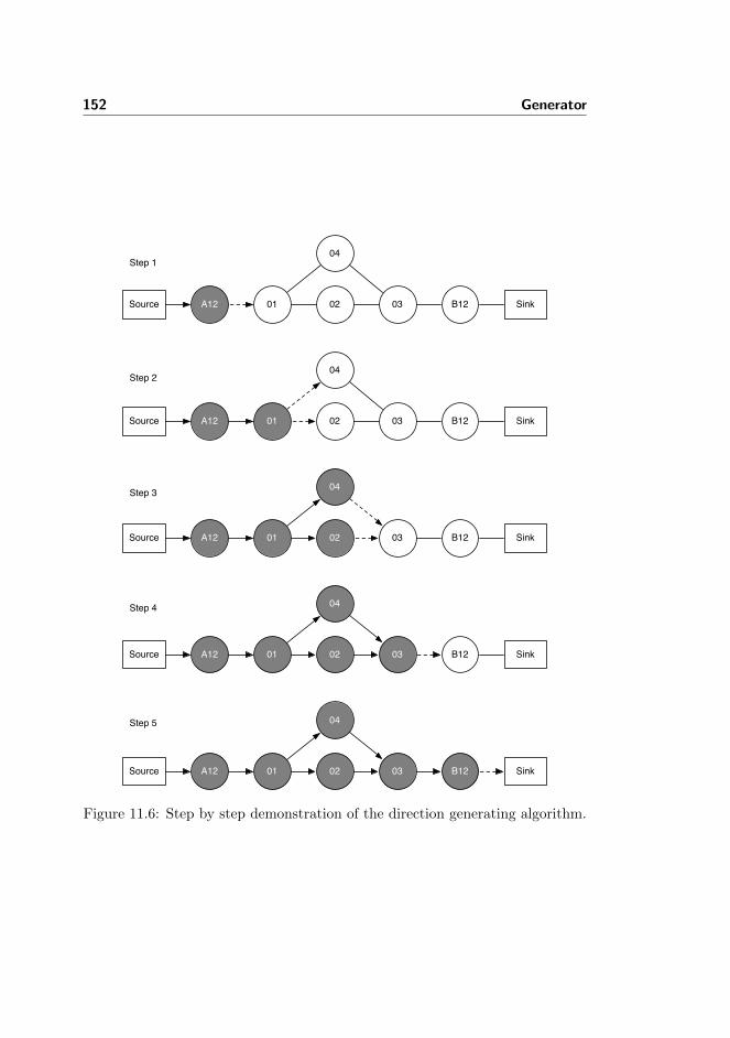
152 Generator
A12 01 02
04
03 B12Source Sink
A12 01 02
04
03 B12Source Sink
A12 01 02
04
03 B12Source Sink
A12 01 02
04
03 B12Source Sink
A12 01 02
04
03 B12Source Sink
Step 1
Step 2
Step 3
Step 4
Step 5
Figure 11.6: Step by step demonstration of the direction generating algorithm.
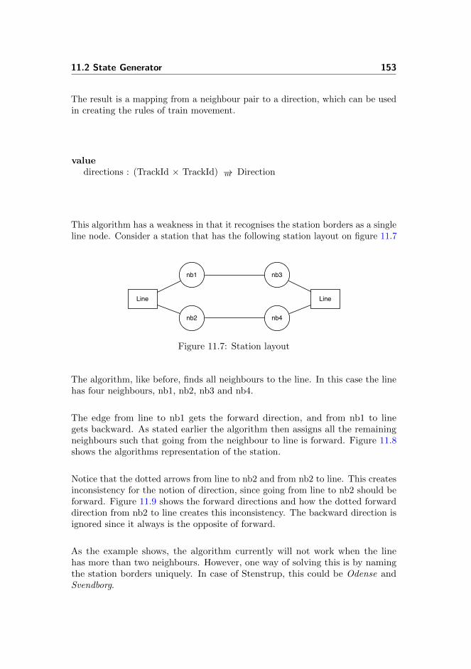
11.2 State Generator 153
The result is a mapping from a neighbour pair to a direction, which can be usedin creating the rules of train movement.
valuedirections : (TrackId × TrackId) →m Direction
This algorithm has a weakness in that it recognises the station borders as a singleline node. Consider a station that has the following station layout on figure 11.7
nb2
nb1
nb4
nb3
Line Line
Figure 11.7: Station layout
The algorithm, like before, finds all neighbours to the line. In this case the linehas four neighbours, nb1, nb2, nb3 and nb4.
The edge from line to nb1 gets the forward direction, and from nb1 to linegets backward. As stated earlier the algorithm then assigns all the remainingneighbours such that going from the neighbour to line is forward. Figure 11.8shows the algorithms representation of the station.
Notice that the dotted arrows from line to nb2 and from nb2 to line. This createsinconsistency for the notion of direction, since going from line to nb2 should beforward. Figure 11.9 shows the forward directions and how the dotted forwarddirection from nb2 to line creates this inconsistency. The backward direction isignored since it always is the opposite of forward.
As the example shows, the algorithm currently will not work when the linehas more than two neighbours. However, one way of solving this is by namingthe station borders uniquely. In case of Stenstrup, this could be Odense andSvendborg.

154 Generator
nb2
nb1 nb3
nb4
Line
backward
forward forward
backward
forward
backward forwardbackward
Figure 11.8: The algorithms representation of the station layout
nb2
nb1
nb4
nb3
Line Lineforward forward
forward forward
forward
forward
Figure 11.9: Station layout with directions

11.3 Transition Generator 155
11.3 Transition Generator
The transition generator facilitates the creation of all the transition rules forthe external events, which involves rules for train movement i.e. entering andleaving a station and track sections, rules for points and rules for buttons.
The list below shows each rule that it generates with reference back to the patternsmentioned earlier and reference to implementation details in this section:
• Entering track section rules (Section 6.3.2 and 11.3.2.2).
• Leaving track section rules (Section 6.3.4 and 11.3.2.3).
• Leaving station rule (Section 6.3.3 and 11.3.2.3).
• Button rules (Section 7.1 and 11.3.3.1).
• Points rules (Section 7.2 and 11.3.3.2).
The specification can be found in appendix E.2.5.
11.3.1 Generating All Transition Rules
All transition rules are generated by calling the function generateTransitionSys-tem. The precondition of the transition generator is, that the interlocking planand the two associations are well-formed.
valuegenerateTransitionSystem : ObjectRelayAssociations ×
InterlockingPlan × TrainMovementAssociations ×Text-set → TransitionRule-set
generateTransitionSystem(ora, ip, tma, buttons) ≡let d = sld(ip),
allSections = allSections(d)in genTrainMovementTransitions(ora, d, tma) ∪
genOtherExternalTransitions(buttons, ora, ip)end
pre isWfInterlockingPlan(ip) ∧isWfTrainMovementAssociations(sld(ip), tma) ∧isWfObjectRelayAssociations(ora, ip)
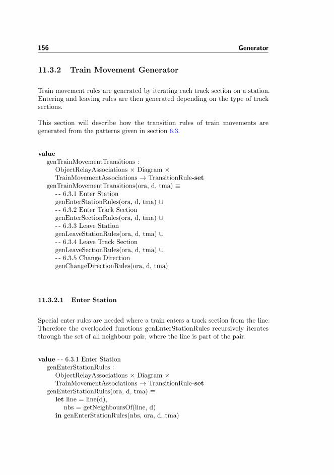
156 Generator
11.3.2 Train Movement Generator
Train movement rules are generated by iterating each track section on a station.Entering and leaving rules are then generated depending on the type of tracksections.
This section will describe how the transition rules of train movements aregenerated from the patterns given in section 6.3.
valuegenTrainMovementTransitions :
ObjectRelayAssociations × Diagram ×TrainMovementAssociations → TransitionRule-set
genTrainMovementTransitions(ora, d, tma) ≡- - 6.3.1 Enter StationgenEnterStationRules(ora, d, tma) ∪- - 6.3.2 Enter Track SectiongenEnterSectionRules(ora, d, tma) ∪- - 6.3.3 Leave StationgenLeaveStationRules(ora, d, tma) ∪- - 6.3.4 Leave Track SectiongenLeaveSectionRules(ora, d, tma) ∪- - 6.3.5 Change DirectiongenChangeDirectionRules(ora, d, tma)
11.3.2.1 Enter Station
Special enter rules are needed where a train enters a track section from the line.Therefore the overloaded functions genEnterStationRules recursively iteratesthrough the set of all neighbour pair, where the line is part of the pair.
value - - 6.3.1 Enter StationgenEnterStationRules :
ObjectRelayAssociations × Diagram ×TrainMovementAssociations → TransitionRule-set
genEnterStationRules(ora, d, tma) ≡let line = line(d),
nbs = getNeighboursOf(line, d)in genEnterStationRules(nbs, ora, d, tma)

11.3 Transition Generator 157
end,
genEnterStationRules : TrackId-set ×ObjectRelayAssociations × Diagram ×TrainMovementAssociations → TransitionRule-set
genEnterStationRules(nbs, ora, d, tma) ≡if nbs = {} then {} else
let nb = hd nbs,nbs′ = nbs \ {nb}
in {genEnterStationRule(nb, ora, d, tma)} ∪genEnterStationRules(nbs′, ora, d, tma) - - Recursive Call
endend
For transition from the line to a track section on the station, a rule is createdfollowing the pattern shown in section 6.3.1.
valuegenEnterStationRule :
TrackId × ObjectRelayAssociations ×Diagram × TrainMovementAssociations → TransitionRule
genEnterStationRule(nb, ora, d, tma) ≡let line = line(d),
dir = getDirection(line, nb, tma),name = genEnterRuleName(line, nb),guard = and( { idle } ∪
proceedAspect(line, nb, ora, d) ),update = { systemBusy,
addTrain(nb, tma),dropTrackRelay(nb, ora),setDirection(nb, dir, tma) }
in mk TransitionRule(name, guard, update)end
where auxiliary functions are defined as follows:
valuegenEnterRuleName : TrackId × TrackId → TextgenEnterRuleName(from, to) ≡ ′′enter_′′ to ′′_from_′′ from,
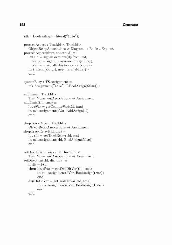
158 Generator
idle : BooleanExp = literal(′′idle′′),
proceedAspect : TrackId × TrackId ×ObjectRelayAssociations × Diagram → BooleanExp-set
proceedAspect(from, to, ora, d) ≡let sId = signalLocations(d)(from, to),
sId gr = signalRelayAssoc(ora)(sId, gr),sId re = signalRelayAssoc(ora)(sId, re)
in { literal(sId gr), neg(literal(sId re)) }end,
systemBusy : TS.Assignment =mk Assignment(′′idle′′, T.BoolAssign(false)),
addTrain : TrackId ×TrainMovementAssociations → Assignment
addTrain(tId, tma) ≡let cVar = getCounterVar(tId, tma)in mk Assignment(cVar, AddAssign(1))end,
dropTrackRelay : TrackId ×ObjectRelayAssociations → Assignment
dropTrackRelay(tId, ora) ≡let rId = getTrackRelay(tId, ora)in mk Assignment(rId, BoolAssign(false))end,
setDirection : TrackId × Direction ×TrainMovementAssociations → Assignment
setDirection(tId, dir, tma) ≡if dir = fwdthen let dVar = getFwdDirVar(tId, tma)
in mk Assignment(dVar, BoolAssign(true))end
else let dVar = getBwdDirVar(tId, tma)in mk Assignment(dVar, BoolAssign(true))end
end

11.3 Transition Generator 159
11.3.2.2 Rules for Entering Track Sections
Each track section can be entered from each of its neighbours. The overloadedfunctions genEnterSectionRules recursively iterates through the set of neighbours,but disregards the neighbours to the line, as these have already been consideredin section 11.3.2.1. For each pair of neighbours, (ts1, ts2), genEnterSectionRuleis then called twice, once with ts1 as the first argument and once with ts2 asthe first argument. This creates an enter rule in both directions, i.e. enteringts1 from ts2 and entering ts2 from ts1.
value - - 6.3.2 Enter Track SectiongenEnterSectionRules : ObjectRelayAssociations × Diagram ×
TrainMovementAssociations → TransitionRule-setgenEnterSectionRules(ora, d, tma) ≡
let nbs = { (tId1, tId2) | (tId1, tId2) : (TrackId × TrackId) •
(tId1, tId2) ∈ neighbours(d) ∧∼isLine(tId1, d) ∧ ∼isLine(tId2, d) }
in genEnterSectionRules(nbs, ora, d, tma)end,
genEnterSectionRules : (TrackId × TrackId)-set ×ObjectRelayAssociations × Diagram ×TrainMovementAssociations → TransitionRule-set
genEnterSectionRules(nbs, ora, d, tma) ≡if nbs = {} then {} else
let (tId1, tId2) = hd nbs,nbs′ = nbs \ {(tId1, tId2)}
in - - From tId1 to tId2genEnterSectionRule(tId1, tId2, ora, d, tma) ∪- - From tId2 to tId1genEnterSectionRule(tId2, tId1, ora, d, tma) ∪- - Recursive CallgenEnterSectionRules(nbs′, ora, d, tma)
endend
As described in section 6.3.4.1, it matters whether a train enters a points sectionfrom the stem side or the branch and likewise if it enters another section from apoints section. Each of these cases are handled in genEnterSectionRule. Recall,from section 4.2.4, that two points sections are not allowed to be neighbours.
value

160 Generator
genEnterSectionRule : TrackId × TrackId ×ObjectRelayAssociations × Diagram ×TrainMovementAssociations → TransitionRule-set
genEnterSectionRule(from, to, ora, d, tma) ≡- - 6.3.2.1 Facing Move - Stem Sideif isPoints(to, d) ∧ isStemNb(to, from, d)then {genEnterLinearSectionRule(from, to, ora, d, tma)}
- - 6.3.2.1 Facing Move - Branch Sideelsif isPoints(from, d) ∧ isBranchNb(from, to, d)then {genEnterFacingBranchSideRule(from, to, ora, d, tma)}
- - 6.3.2.1 Trailing Move - Stem Sideelsif isPoints(from, d) ∧ isStemNb(from, to, d)then {genEnterLinearSectionRule(from, to, ora, d, tma)}
- - 6.3.2.1 Trailing Move - Branch Sideelsif isPoints(to, d) ∧ isBranchNb(to, from, d)then {genEnterFacingBranchSideRule(from, to, ora, d, tma), - - Correct pos
genEnterTrailingBranchSideRule(from, to, ora, d, tma)} - - Incorrect pos
else - - 6.3.2 Linear{genEnterLinearSectionRule(from, to, ora, d, tma)}
end
The structure of the functions for each case is the same, but the rule that isgenerated varies slightly. Therefore only genEnterLinearSectionRule will beshown and explained here. In fact it follows the same structure as for generatingenter station rules, which where shown in section 11.3.2.1.
valuegenEnterLinearSectionRule : TrackId × TrackId ×
ObjectRelayAssociations × Diagram ×TrainMovementAssociations → TransitionRule
genEnterLinearSectionRule(from, to, ora, d, tma) ≡let dir = getDirection(from, to, tma),
name = ′′enter_′′ to ′′_from_′′ from,guard = and({ idle,trackOccupied(from, tma),direction(from, to, tma),notConnected(from, to, tma) } ∪
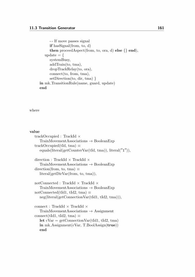
11.3 Transition Generator 161
- - If move passes signalif hasSignal(from, to, d)then proceedAspect(from, to, ora, d) else {} end),
update = {systemBusy,addTrain(to, tma),dropTrackRelay(to, ora),connect(to, from, tma),setDirection(to, dir, tma) }
in mk TransitionRule(name, guard, update)end
where
valuetrackOccupied : TrackId ×
TrainMovementAssociations → BooleanExptrackOccupied(tId, tma) ≡
equals(literal(getCounterVar(tId, tma)), literal(′′1′′)),
direction : TrackId × TrackId ×TrainMovementAssociations → BooleanExp
direction(from, to, tma) ≡literal(getDirVar(from, to, tma)),
notConnected : TrackId × TrackId ×TrainMovementAssociations → BooleanExp
notConnected(tId1, tId2, tma) ≡neg(literal(getConnectionVar(tId1, tId2, tma))),
connect : TrackId × TrackId ×TrainMovementAssociations → Assignment
connect(tId1, tId2, tma) ≡let cVar = getConnectionVar(tId1, tId2, tma)in mk Assignment(cVar, T.BoolAssign(true))end
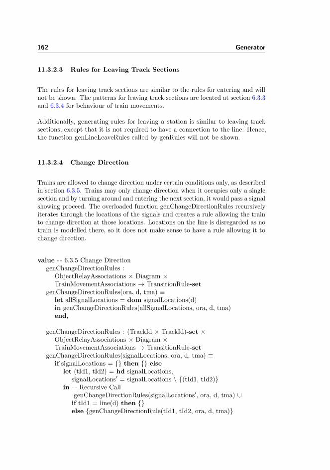
162 Generator
11.3.2.3 Rules for Leaving Track Sections
The rules for leaving track sections are similar to the rules for entering and willnot be shown. The patterns for leaving track sections are located at section 6.3.3and 6.3.4 for behaviour of train movements.
Additionally, generating rules for leaving a station is similar to leaving tracksections, except that it is not required to have a connection to the line. Hence,the function genLineLeaveRules called by genRules will not be shown.
11.3.2.4 Change Direction
Trains are allowed to change direction under certain conditions only, as describedin section 6.3.5. Trains may only change direction when it occupies only a singlesection and by turning around and entering the next section, it would pass a signalshowing proceed. The overloaded function genChangeDirectionRules recursivelyiterates through the locations of the signals and creates a rule allowing the trainto change direction at those locations. Locations on the line is disregarded as notrain is modelled there, so it does not make sense to have a rule allowing it tochange direction.
value - - 6.3.5 Change DirectiongenChangeDirectionRules :
ObjectRelayAssociations × Diagram ×TrainMovementAssociations → TransitionRule-set
genChangeDirectionRules(ora, d, tma) ≡let allSignalLocations = dom signalLocations(d)in genChangeDirectionRules(allSignalLocations, ora, d, tma)end,
genChangeDirectionRules : (TrackId × TrackId)-set ×ObjectRelayAssociations × Diagram ×TrainMovementAssociations → TransitionRule-set
genChangeDirectionRules(signalLocations, ora, d, tma) ≡if signalLocations = {} then {} else
let (tId1, tId2) = hd signalLocations,signalLocations′ = signalLocations \ {(tId1, tId2)}
in - - Recursive CallgenChangeDirectionRules(signalLocations′, ora, d, tma) ∪
if tId1 = line(d) then {}else {genChangeDirectionRule(tId1, tId2, ora, d, tma)}

11.3 Transition Generator 163
endend
end
The transition rule itself is created by the function genChangeDirectionRule,which is in the same way as the other transition generating functions.
valuegenChangeDirectionRule : TrackId × TrackId ×
ObjectRelayAssociations × Diagram ×TrainMovementAssociations → TransitionRule
genChangeDirectionRule(from, to, a, d, tma) ≡let curDir = directions(tma)(from, to),
oppDir = oppositeDirection(curDir),name = ′′change_direction_at_′′ from ′′_towards_′′ to,guard = { idle,
trackOccupied(from, tma),direction(from, to, tma) } ∪proceedAspect(from, to, a, d) ∪isTailOfTrainGuards(from, to, d, tma),
update = { setDirection(from, oppDir, tma),removeDirection(from, curDir, tma)}
in mk TransitionRule(name, T.and(guard), update)end
11.3.3 Other External Events Generator
In addition to the train movements, there are two kinds of external events thathave to be modelled. These are the behaviour of buttons and the operation ofpoints, as described in section 7.
The function genOtherExternalTransitions is supplied by the generator of otherexternal events and is called by the transition generator.
valuegenOtherExternalTransitions :
Text-set × ObjectRelayAssociations ×InterlockingPlan → TransitionRule-set

164 Generator
genOtherExternalTransitions(buttons, ora, ip) ≡- - 7.1 Button BehaviourgenAllButtonRules(buttons) ∪- - 7.2 Points BehaviourgenAllPointsOpRules(ora, ip)
The following will explain the generation of the transitions that describe thebutton and points behaviour in detail.
11.3.3.1 Rules for Buttons
The button behaviour patterns are described in section 7.1. The rules for buttonpresses are simple and so is the generator that generates them. To generate thetransition rules for pressing buttons, the set of all button identifiers is required.Refer to the case study of Stenstrup where button identiers are provided shownin section 13.1.5.
value - - 7.1 Button BehaviourgenAllButtonRules : Text-set → TransitionRule-setgenAllButtonRules(bs) ≡
if bs = {} then {} elselet b = hd bs, bs′ = bs \ {b}in {genButtonRule(b)} ∪ genAllButtonRules(bs′)end
end,
genButtonRule : Text → TransitionRulegenButtonRule(b) ≡
mk TransitionRule(′′pushButton_′′ b,T.literal(′′idle′′),{ busySystem, mk Assignment(b, BoolAssign(true)) })
A transition rule is generated for each button, by recursively iterating throughthe set of all buttons. The rule is very simple. If the system is standing idle, thebutton can be pressed. This causes the system to become busy and the variablethat represent the state of the button is set to true, which represents that thebutton is pressed.

11.3 Transition Generator 165
11.3.3.2 Rules for Operation of Points
The rule patterns for operation of points are described in section 7.2.
Even though these rules should be generated from the circuit diagrams, they canalso be generated from the interlocking plan.
The rules are generated as part of the transition generator and are mostly trivial.For each points section in the station layout diagram, the four rules are generated.The difficult part is figuring out which routes covers the points. This is done bysearching for each points section in the track section part of each route in thetrain route table. If the track relay for the points section should be drawn beforethe route can be locked, then the points section is indeed part of the route.
A total of four transition rules are needed for each points section. The overloadedfunctions genAllPointsOpRules collectively calls genPointsOpRules for eachpoints section on the station.
value - - 7.2 Points BehaviourgenAllPointsOpRules : ObjectRelayAssociations ×
InterlockingPlan → TransitionRule-setgenAllPointsOpRules(ora, ip) ≡
let d = sld(ip),allPoints = allPoints(d)
in genAllPointsOpRules(allPoints, ora, ip)end,
genAllPointsOpRules :TrackId-set × ObjectRelayAssociations ×InterlockingPlan → TransitionRule-set
genAllPointsOpRules(allPoints, ora, ip) ≡if allPoints = {} then {} else
let p = hd allPoints,allPoints′ = allPoints \ {p}
in genPointsOpRules(p, ora, ip) ∪genAllPointsOpRules(allPoints′, ora, ip) - - Recursive Call
endend
Each of the four transition rules are then generated by genPointsOpRules.
value

166 Generator
genPointsOpRules :TrackId × ObjectRelayAssociations ×InterlockingPlan → TransitionRule-set
genPointsOpRules(pId, ora, ip) ≡let d = sld(ip),
trt = trt(ip),rlrs = getRouteLockingRelaysCoveringP(pId, ora, trt) in {
- - From plus to intermediatemk TransitionRule(
′′plusToIntermediate′′ pId,genPointsOpGuard(pId, plus, rlrs, ora, d),genPointsOpUpd(pId, plus, false, ora, d) ),
- - From intermediate to plusmk TransitionRule(
′′intermediateToPlus′′ pId,genPointsOpGuard(pId, rlrs, ora, d),genPointsOpUpd(pId, plus, true, ora, d) ),
- - From minus to intermediatemk TransitionRule(
′′minusToIntermediate′′ pId,genPointsOpGuard(pId, minus, rlrs, ora, d),genPointsOpUpd(pId, minus, false, ora, d) ),
- - From intermediate to minusmk TransitionRule(
′′intermediateToMinus′′ pId,genPointsOpGuard(pId, rlrs, ora, d),genPointsOpUpd(pId, minus, true, ora, d) )
}end
The following explains the remaining functions used to generate the transitionsfor the points operation.
genPointsOpGuard Are two overloaded functions, which handle the casesof moving from one of the two locked positions to intermediate and the otherway, respectively. They call getRouteLockingRelaysCoveringP to get the routelocking relays that covers the points section in question.

11.4 Assertion Generator 167
getRouteLockingRelaysCoveringP A wrapper function that finds all theroutes from the train route table and calls getRLRsCoveringP. Then getRLRsCov-eringP recursively runs through the routes and calls getRLRCoveringP. Finally,if the given points section is covered by the given route, then the related routelocking relay is returned by getRLRCoveringP.
genPointsOpUpdate Returns a set of assignments by updating the idle andupdating the points relay to either being locked into a position or intermediatedepending on which case.
convRelayIdsToLiterals Converts a set of relay ids into literals to be usedin a boolean expression.
11.4 Assertion Generator
This section introduces the assertion generator and describes important partsin the specification. The patterns introduced in chapter 9 about inter-modelconsistency, and chapter 10 about safety properties described the assertions ingeneral form. This section will use these patterns and apply them as guidelinesto implement the assertion generator.
The assertion generator handles the generation of the safety properties andinter-model consistency conditions. The safety properties consists of no collisionand no derailing assertions and other requirements derived from the train routetable.
The inter-model consistency consists of conditions that ensure the interactionbetween the train movement model and the internal relay system model behavesas expected.
Thus, the assertion generator is split into three parts, one for inter-model con-sistency, one for safety conditions assertions and one for the assertions derivedfrom the train route table.
Inter-model consistency consist of the following conditions each with referenceback to the patterns mentioned earlier.
• Track Occupation (Section 9.2).
168 Generator
• Track Free (Section 9.3).
• Train Direction (Section 9.4).
• Points Configuration (Section 9.5).
• Train Connection (Section 9.6).
The basic safety properties consists of the following conditions each with areference back to the patterns mentioned earlier.
• No collision (Section 10.2).
• No derailing (Section 10.3).
And lastly, the safety properties derived from the train route table consists ofthe following conditions each with a reference back to the patterns mentionedearlier.
• Points Position (Section 10.4).
• Signal (Section 10.5).
• Signal Release (Section 10.6).
• Conflicting Routes (Section 10.7).
• Train Route Release (Section 10.8).
The following sections will present a description of how a single assertion isgenerated by introducing some general rules and then an overview of how theassertions are generated. Finally an example from our specification showing howthe signal release assertion is generated.
11.4.1 Generating a Single Assertion
RSL-SAL assertions have the following general form:
[ assertionName ] TransitionSystem ` TemporalLogic

11.4 Assertion Generator 169
where assertionName is a unique identifier for the assertion. The Transistion-System is the name of the transition system and TemporalLogic is the LTLexpression checking the validity of the model/transition system.
The abstract syntax of this is given by the RSL Assertion type. This type wasdescribed in section 4.4.4.
In the example below the generateSomeAssertion function accepts two para-meters. This is simply to show the structure, where the number of parameterstypically range from two to five.
Generating an assertion has the following general form:
generateSomeAssertion : ... × ... → T.AssertiongenerateSomeAssertion(..., ...) ≡
(′′some_assertion_name′′ toString(...),TransitionSystem,genSomeFormula(..., ...)
),
The name is made unique by concatenating an indicative identifier to the name,where we usually use a track section id, route id or signal id. The TransitionSystemis simply a variable, that contains the name of the current transition systemused in all the generated assertions, namely InterlockingSystem.
Finally, the genSomeFormula function is invoked to generate the LTL expressions.In the simplest form all the assertions consist of a boolean expression implyinganother boolean expression. The inter-model consistency conditions and thesafety properties described in chapter 9 and chapter 10 all requires that theexpressions must hold true in all states. Thus, applying globally on the generalform.
By invoking the function genSomeFormula it returns a LTLformula defined insection 4.4.4.
Hence, the generated LTLformula has the following general form:
genSomeFormula : ... × ... → LTLformulagenSomeFormula(..., ...) ≡g(impl(...,...))
This would generate the following LTL formula:
170 Generator
G(...⇒ ...)
11.4.2 Specifying the Assertion Generator
AssertionGenerator.rsl supply the function generateAssertions, which makes callsto each of the subgenerators.
valuegenerateAssertions :
ObjectRelayAssociations × InterlockingPlan ×TrainMovementAssociations → Assertion-set
generateAssertions(ora, ip, tma) ≡genConsistencyAssertions(ora, ip, tma) ∪genSafetyAssertions(ora, ip, tma) ∪genTrtAssertions(ora, ip, tma)
pre isWfInterlockingPlan(ip) ∧isWfTrainMovementAssociations(sld(ip), tma) ∧isWfObjectRelayAssociations(ora, ip)
11.4.2.1 Consistency Assertion Generator
The inter-model consistency assertions are generated by the consistency assertiongenerator. The more general assertion generator call the genConsistencyAsser-tions method of the consistency assertion generator.
valuegenConsistencyAssertions :
ObjectRelayAssociations × InterlockingPlan ×TrainMovementAssociations → Assertion-set
genConsistencyAssertions(ora, ip, tma) ≡- - 9.2 Track OccupationgenerateOccupationAssertions(ora, ip, tma) ∪- - 9.3 Track FreegenerateFreeAssertions(ora, ip, tma) ∪- - 9.4 Train DirectiongenerateDirectionAssertions(ip, tma) ∪- - 9.5 Points Configuration

11.4 Assertion Generator 171
generatePointsConfigurationAssertions(ora, ip) ∪- - 9.6 Train ConnectiongenerateConnectionAssertions(ip, tma)
pre isWfInterlockingPlan(ip) ∧isWfTrainMovementAssociations(sld(ip), tma) ∧isWfObjectRelayAssociations(ora, ip)
Consider the track occupation consistency requirement presented in section 9.2.In the following, the specification of the generator for the related assertions willbe explained.
value - - 9.2 Track OccupationgenerateOccupationAssertions : ObjectRelayAssociations ×
InterlockingPlan × TrainMovementAssociations → Assertion-setgenerateOccupationAssertions(ora, ip, tma) ≡
let d = sld(ip),sections = allLinears(d) ∪ allPoints(d) - - NB: No line pieces!
in generateOccupationAssertions(sections, ora, tma)end
Track Occupation requires that there must be consistency, for each track section,between the track relay variables and the track counters. Therefore the set of alltrack sections is given to generateOccupationAssertions.
valuegenerateOccupationAssertions :
TrackId-set × ObjectRelayAssociations ×TrainMovementAssociations → Assertion-set
generateOccupationAssertions(sections, ora, tma) ≡if sections = {} then {} else
let s = hd sections,sections′ = sections \ {s}
in {generateOccupationAssertion1(s, ora, tma),generateOccupationAssertion2(s, ora, tma)} ∪generateOccupationAssertions(sections′, ora, tma) - - Recursive
endend
The function generateOccupationAssertions runs through all the track sectionsrecursively and calls the two functions which are respondsible for generating theactual assertion for a given track section.

172 Generator
valuegenerateOccupationAssertion1 :
TrackId × ObjectRelayAssociations ×TrainMovementAssociations → Assertion
generateOccupationAssertion1(s, ora, tma) ≡(′′occ_′′ s,genOccuFormula1(s, ora, tma)),
genOccuFormula1 :TrackId × ObjectRelayAssociations ×TrainMovementAssociations → LTLformula
genOccuFormula1(s, ora, tma) ≡g(impl(b(greaterthan(
literal(getCounterVar(s, tma)),literal(′′0′′))),neg(ltrl(trackRelayAssoc(ora)(s))))),
generateOccupationAssertion2 is very similar to generateOccupationAssertion1.However, it generates the other direction of the bi-implication.
valuegenerateOccupationAssertion2 :
TrackId × ObjectRelayAssociations ×TrainMovementAssociations → Assertion
generateOccupationAssertion2(s, ora, tma) ≡( ′′occ_′′ s ′′_′′,genOccuFormula2(s, ora, tma) ),
genOccuFormula2 :TrackId × ObjectRelayAssociations ×
TrainMovementAssociations → LTLformulagenOccuFormula2(s, ora, tma) ≡
g(impl(neg(ltrl(trackRelayAssoc(ora)(s))),
b(greaterthan(literal(getCounterVar(s, tma)),literal(′′0′′)))))
The functions for the other consistancy requirements are similar.

11.4 Assertion Generator 173
11.4.2.2 Safety Generator
This subgenerator is respondsable for generating the assertions for the basicsafety requirements, i.e. no collision and no derailing.
valuegenSafetyAssertions :
ObjectRelayAssociations × InterlockingPlan ×TrainMovementAssociations → Assertion-set
genSafetyAssertions(ora, ip, tma) ≡- - 10.2 No CollisiongenNoCollisionAssertions(ip, tma) ∪- - 10.3 No DerailinggenNoDerailingAssertions(ora, ip, tma)
pre isWfInterlockingPlan(ip) ∧isWfTrainMovementAssociations(sld(ip), tma) ∧isWfObjectRelayAssociations(ora, ip)
The no collistion assertions are generated by the function genNoCollisionAsser-tions, by recursively running through each track section on the station.
value - - 10.2 No CollisiongenNoCollisionAssertions : InterlockingPlan ×
TrainMovementAssociations → Assertion-setgenNoCollisionAssertions(ip, tma) ≡
let d = sld(ip),sections = allLinears(d) ∪ allPoints(d) - - NB: No line pieces!
in generateNoCollisionAssertions(sections, tma)end,
generateNoCollisionAssertions : TrackId-set ×TrainMovementAssociations → Assertion-set
generateNoCollisionAssertions(sections, tma) ≡if sections = {} then {} else
let s = hd sections,sections′ = sections \ {s}
in {generateNoCollisionAssertion(s, tma)} ∪generateNoCollisionAssertions(sections′, tma) - - Recursive call
endend
174 Generator
The pattern described in sections 10.2 and 10.3 is applied to each track sectionon the station.
valuegenerateNoCollisionAssertion : TrackId ×
TrainMovementAssociations → AssertiongenerateNoCollisionAssertion(s, tma) ≡
(′′no_collision_′′ s,genNoColFormula(s, tma) ),
genNoColFormula : TrackId ×TrainMovementAssociations → LTLformula
genNoColFormula(s, tma) ≡g(b(lessthan(literal(getCounterVar(s, tma)), literal(′′2′′))))
11.4.2.3 TRT Generator
The trt generator creates the assertions of the requirements derived from thetrain route table. Each requirement, as described in section 10.4 through 10.8.
valuegenTrtAssertions :
ObjectRelayAssociations × InterlockingPlan ×TrainMovementAssociations → Assertion-set
genTrtAssertions(ora, ip, tma) ≡- - 10.4 Points PositiongenPointsPositionAssertions(ora, trt(ip)) ∪- - 10.5 SignalgenSignalAssertions(ora, ip) ∪- - 10.6 Signal ReleasegenSignalReleaseAssertions(ora, ip) ∪- - 10.7 Conflicting RoutesgenConflictingRoutesAssertions(ora, ip) ∪- - 10.8 Train Route ReleasegenTrainRouteReleaseAssertions(ora, ip)
pre isWfInterlockingPlan(ip) ∧isWfTrainMovementAssociations(sld(ip), tma) ∧isWfObjectRelayAssociations(ora, ip)

11.5 Output 175
The implementation of each requirement is very similar to what has already beenshown in the preceeding section and will therefore not be discussed further here.Refer to the source code for the entire specification.
11.5 Output
The Stenstrup file instantiates InterlockingPlan and ObjectRelayAssociationsfor Stenstrup station. By executing the test case within the Stenstrup file it willinvoke the generator, asking it to generate the transition system for Stenstrupand the unparser to print it in a form that RSL-SAL accepts.
11.5.1 Unparser
The unparser takes a transition system and prints a textual representation of it,using the syntax of RSL-SAL.
A transition system in RSL-SAL looks as follows:
transition system [ name ]local[ variable decl ]in[ transition decl ]end
ltl assertions[ assertions decl ]
The unparser creates this structure and calls the overloaded method print oneach component of the transition system, such that they are inserted at the rightplace.
valueprint : TransitionSystem → Textprint(ts) ≡
let name = name(ts),state = state(ts),

176 Generator
transitionRules = transitionRules(ts),assertions = assertions(ts)
in ′′\ntransition_system\n\n[′′ name ′′]\n\nlocal′′ print(state) ′′\n\nin\n′′ print(transitionRules) ′′\n\nend\n\nltl_assertion\n′′ print(name, assertions) ′′\n′′
end
11.5.1.1 State
The state is unparsed by recursively running through all the variables in thestate space. Each variable is written on its own line and they are seperated bycommas.
valueprint : Var-set → Textprint(vars) ≡
if vars = {} then ′′′′ elselet var = hd vars, vars′ = vars \ {var}in ′′\n′′ print(var)
if vars′ = {} then ′′′′
else ′′,′′ print(vars′)end
endend
The identifier of the variable is written and then the type definition and initialassignment is unparsed.
valueprint : Var → Textprint(var) ≡
let id = id(var),val = val(var)
in id ′′ : ′′ print(val)end
The unparser support the types boolean and natural numbers.

11.5 Output 177
valueprint : Val → Textprint(val) ≡
case val ofmk BoolVal(b) → ′′Bool := ′′ toString(b),mk NatVal(n) → ′′Nat := ′′ toString(n)
end
11.5.1.2 Transitions
The transition rules are written out using the same method as the variables.However, they are separated by the choice operator, [=].
valueprint : TransitionRule-set → Textprint(trs) ≡
if trs = {} then ′′′′
else let tr = hd trs, trs′ = trs \ {tr}in ′′\n′′ print(tr)
if trs′ = {} then ′′′′
else ′′\n[=]′′ print(trs′)end
endend
The name can be completely unparsed at this point, however both the guardand update needs further treatment.
valueprint : TransitionRule → Textprint(tr) ≡
′′[′′ name(tr) ′′]\n′′ print(guard(tr)) ′′ ==>\n′′ print(assignments(tr))
Recall that the guard is a boolean expression and is unparsed in a similar fashionas the update and will therefore not be shown. The update consists of assignmentsseparated by commas.

178 Generator
valueprint : MultipleAssignment → Textprint(assignments) ≡
if assignments = {} then ′′′′ elselet assignment = hd assignments,
assignments′ = assignments \ {assignment}in print(assignment)
if assignments′ = {} then ′′′′
else ′′, ′′ print(assignments′)end
endend
Each different type of assignment is treated independently.
valueprint : Assignment → Textprint(assignment) ≡
let id = id(assignment)in case assign(assignment) of
BoolAssign(b) → id ′′’ = ′′ toString(b),NatAssign(n) → id ′′’ = ′′ toString(n),AddAssign(a) → id ′′’ = ′′ id ′′ + ′′ toString(a),SubAssign(s) → id ′′’ = ′′ id ′′ - ′′ toString(s)end
end
11.5.1.3 Assertions
Assertions are written under the ltl assertions tag, where each assertion gets itsown line separated by comma.
valueprint : Text × Assertion-set → Textprint(tsName, asserts) ≡
if asserts = {} then ′′′′ elselet assert = hd asserts, asserts′ = asserts \ {assert}in ′′\n′′ print(tsName, assert)
if asserts′ = {} then ′′′′

11.5 Output 179
else ′′,\n′′ print(tsName, asserts′)end
endend
The LTL formular is unparsed in a similar manner as the boolean expression(not shown here).
valueprint : Text × (Text × LTLformula) → Textprint(tsName, (nm, ltl)) ≡
′′[′′ nm ′′] ′′ tsName ′′ |-\n′′ print(ltl)

180 Generator

Chapter 12
Test
The test strategy of the implementation is to create scenarios of invalid andvalid data models and associations. The expected invalid scenarios should thenbe caught by the well-formedness expressions defined within each of the datamodels and associations, as well as the expected valid scenarios should satisfythe requirements.
In the following chapter a thorough test of the station layout will be conductedin section 12.1. The tests of train route table, transition system, train movementassociations and object relay association uses the same test strategy as thestation layout. These tests can be found in appendix E.5.2, E.5.3, E.5.5, E.5.4,respectively.
All of the tests can be found in appendix E.5, and all the output from each testcan be found in appendix F.3.
12.1 Station Layout
The test strategy for the station layout diagram is to create a simple stationconsisting of two linear track sections 02 and 03, and a points sections 01, where

182 Test
Test case name Description
isWfIdentifiers fail id 01 used both as a linear section and a pointssection
isWfIdentifiers succeed distinct ids used in linear, signal and point
Table 12.1: Test of well-formedness of identifiers
each linear track section is connected to the points section at the branch side,and a line connected to the stem, as illustrated on figure 12.1. Additionally, thepoints section is covered by two signals A and B at the branch side. Using thesimple station allows us to easily modify it creating invalid station layouts.
Line 01 02
03
A
B
Figure 12.1: A simple station for testing the station layout diagram well-formedness.
Each well-formedness requirement defined in the station layout is to be tested.The tables from 12.1–12.7 are divided in groups each listed with names of well-formedness expressions followed by fail or success. Fail indicates that it isexpected to fail, while success indicates a scenario that satisfies the requirementsby the given well-formedness expression. Each test is attached with a descriptionof the tested scenario.
12.2 Results
Each test case shown for the station layout diagram using the simple stationpassed all tests. All the invalid input failed as expected, and the valid inputsucceeded as expected.
All the tested output can be found in appendix F.3, where each test case isprefixed with the name of the well-formedness expression followed by either failor succeed. The result is printed to the right of the name, where true denotesthe test was as expected, and false would imply a failed test.
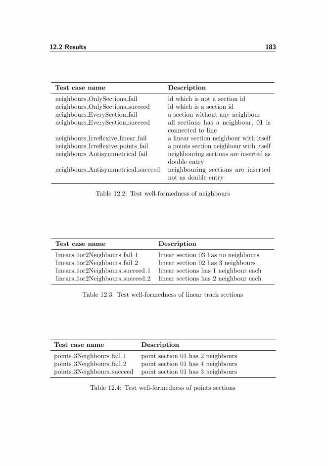
12.2 Results 183
Test case name Description
neighbours OnlySections fail id which is not a section idneighbours OnlySections succeed id which is a section idneighbours EverySection fail a section without any neighbourneighbours EverySection succeed all sections has a neighbour, 01 is
connected to lineneighbours Irreflexive linear fail a linear section neighbour with itselfneighbours Irreflexive points fail a points section neighbour with itselfneighbours Antisymmetrical fail neighbouring sections are inserted as
double entryneighbours Antisymmetrical succeed neighbouring sections are inserted
not as double entry
Table 12.2: Test well-formedness of neighbours
Test case name Description
linears 1or2Neighbours fail 1 linear section 03 has no neighbourslinears 1or2Neighbours fail 2 linear section 02 has 3 neighbourslinears 1or2Neighbours succeed 1 linear sections has 1 neighbour eachlinears 1or2Neighbours succeed 2 linear sections has 2 neighbour each
Table 12.3: Test well-formedness of linear track sections
Test case name Description
points 3Neighbours fail 1 point section 01 has 2 neighbourspoints 3Neighbours fail 2 point section 01 has 4 neighbourspoints 3Neighbours succeed point section 01 has 3 neighbours
Table 12.4: Test well-formedness of points sections

184 Test
Test case name Description
branchNeighbours areNeighbours fail the neighbours in the branchneighbours relation does notmatch the neighbours relation
branchNeighbours areNeighbours succeed the neighbours in the branchneighbours relation match theneighbours relation
branchNeighbours FirstIsPoints fail The first parameter in the tupleis a linear section
branchNeighbours FirstIsPoints succeed The first parameter in the tupleis a points section
branchNeighbours everyPoints fail Not every points defined in all-Points are used in branchNeig-bours
branchNeighbours everyPoints succeed every points defined in allPointsand are used in branchNeig-bours
Table 12.5: Test well-formedness of branch neighbours
Test case name Description
signalLocation UsesExistingSignals fail signal location does not useexisting signals from allsig-nals
signalLocation UsesExistingSignals succeed signal location use existingsignals from allsignals
signalsArePlacedAtValtIdNeighbours fail signals are placed at invalidlocations (between sectionsthat does not exist)
signalsArePlacedAtValtIdNeighbours succeed signals are placed at valid loc-ations (between existing sec-tions)
Table 12.6: Test well-formedness of signals

12.2 Results 185
Test case name Description
pointMachines areSymmetrical fail1 inconsistency betweenpointMachineTrack andtrackPointMachine
pointMachines areSymmetrical fail2 inconsistency betweenpointMachineTrack andtrackPointMachine
pointMachines areSymmetrical fail3 inconsistency betweenpointMachineTrack andtrackPointMachine
pointMachines areSymmetrical succeed consistency between point-MachineTrack and track-PointMachine
pointMachines ExistingTrackSections fail uses a non-existing pointssection
pointMachines ExistingTrackSections succeed uses an existing points sec-tion
Table 12.7: Test well-formedness of point machines

186 Test

Chapter 13
Case Study - Stenstrup
This chapter shows the entire process of verifying the interlocking system ofStenstrup station, from filling in the data representation to model checking thegenerated model of the interlocking system and environment.
This case study follows the user guide given in appendix C.
Refer to appendix B for the documentation of Stenstrup and appendix E.4.5 forthe specification.
Section 13.1 describes, using Stenstrup station, how it is constructed step bystep.
Section 13.2 then shows how to generate the external events by using Stenstrup.Some of the generated output is then compared with variables and transitionrules for the external behaviour.
13.1 Defining Stenstrup
Beginning from the provided template (see appendix E.4.4), every entry is filledout as described in the following sections.

188 Case Study - Stenstrup
13.1.1 Interlocking Plan
An interlocking plan consists of a station layout diagram and a train route table.
valuestenstrupIP : InterlockingPlan =
mk InterlockingPlan(stenstrupSLD,stenstrupTRT
)
13.1.2 Station Layout Diagram
The station layout diagram of Stenstrup is defined as a well-formed stationlayout diagram. The content of each of the constituents is shown in the followingsections.
valuestenstrupSLD : Diagram =
mk Diagram(′′line′′,allLinears,allPoints,allSignals,neighbours,branchNeighbours,pointMachineTrack,trackPointMachine,signalLocations
)
13.1.2.1 Physical Objects
The linear track sections A12, 02, 04 and B12 are stored in the set allLinears,the points sections 01 and 03 are stored in allPoints and the signals A, B, D, F,G and H are stored in allSignals.
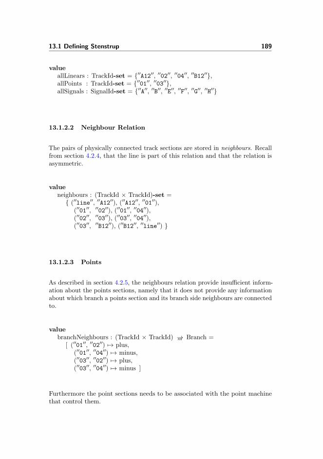
13.1 Defining Stenstrup 189
valueallLinears : TrackId-set = {′′A12′′, ′′02′′, ′′04′′, ′′B12′′},allPoints : TrackId-set = {′′01′′, ′′03′′},allSignals : SignalId-set = {′′A′′, ′′B′′, ′′E′′, ′′F′′, ′′G′′, ′′H′′}
13.1.2.2 Neighbour Relation
The pairs of physically connected track sections are stored in neighbours. Recallfrom section 4.2.4, that the line is part of this relation and that the relation isasymmetric.
valueneighbours : (TrackId × TrackId)-set ={ (′′line′′, ′′A12′′), (′′A12′′, ′′01′′),
(′′01′′, ′′02′′), (′′01′′, ′′04′′),(′′02′′, ′′03′′), (′′03′′, ′′04′′),(′′03′′, ′′B12′′), (′′B12′′, ′′line′′) }
13.1.2.3 Points
As described in section 4.2.5, the neighbours relation provide insufficient inform-ation about the points sections, namely that it does not provide any informationabout which branch a points section and its branch side neighbours are connectedto.
valuebranchNeighbours : (TrackId × TrackId) →m Branch =
[ (′′01′′, ′′02′′) 7→ plus,(′′01′′, ′′04′′) 7→ minus,(′′03′′, ′′02′′) 7→ plus,(′′03′′, ′′04′′) 7→ minus ]
Furthermore the point sections needs to be associated with the point machinethat control them.

190 Case Study - Stenstrup
valuepointMachineTrack : PointMachineId →m TrackId =
[ ′′01′′ 7→ ′′01′′,′′02′′ 7→ ′′03′′ ],
trackPointMachine : TrackId →m PointMachineId =[ ′′01′′ 7→ ′′01′′,
′′03′′ 7→ ′′02′′ ]
13.1.2.4 Signals
Finishing out the station layout diagram of Stenstrup, is defining the signalslocations.
valuesignalLocations : (TrackId × TrackId) →m SignalId =
[ (′′line′′, ′′A12′′) 7→ ′′A′′, (′′line′′, ′′B12′′) 7→ ′′B′′,(′′02′′, ′′01′′) 7→ ′′E′′, (′′04′′, ′′01′′) 7→ ′′F′′,(′′02′′, ′′03′′) 7→ ′′G′′, (′′04′′, ′′03′′) 7→ ′′H′′ ]
13.1.3 Train Route Table
The train route table of Stenstrup (fig. 2.15), shows that Stenstrup has eighttrain routes. The data for each route is stored in a DataRow structure. Onlythe content of two of the routes are shown here. Please refer to the full listing inappendix E.4.5 for the remaining routes.
valuestenstrupTRT : TrainRouteTable =
[ ′′2′′ 7→ dataRow2, ′′3′′ 7→ dataRow3,′′5′′ 7→ dataRow5, ′′6′′ 7→ dataRow6,′′7′′ 7→ dataRow7, ′′8′′ 7→ dataRow8,′′9′′ 7→ dataRow9, ′′10′′ 7→ dataRow10 ]
Recall the specification of a DataRow from section 4.3.2. The following shows aDataRow object instantiated with the data from the row of train route 2.

13.1 Defining Stenstrup 191
valuedataRow2 : DataRow =
mk DataRow({′′03′′, ′′B12′′},[ ′′A′′ 7→ gr, ′′B′′ 7→ arbitrary, ′′E′′ 7→ arbitrary,
′′F′′ 7→ re, ′′G′′ 7→ re, ′′H′′ 7→ arbitrary ],[ ′′01′′ 7→ plus, ′′02′′ 7→ plus ],[ ′′A12′′ 7→ true, ′′01′′ 7→ true, ′′02′′ 7→ true,
′′04′′ 7→ false, ′′03′′ 7→ true, ′′B12′′ 7→ true ],( ′′A′′, ′′A12′′ ),( ((′′01′′, dropped), (′′02′′, drawn)),
((′′02′′, dropped), (′′01′′, drawn)) ),[ ′′2′′ 7→ true, ′′3′′ 7→ true, ′′5′′ 7→ true, ′′6′′ 7→ true,
′′7′′ 7→ true, ′′8′′ 7→ true, ′′9′′ 7→ false, ′′10′′ 7→ true ])
The data for train route 10 is shown below.
valuedataRow10 : DataRow =
mk DataRow({},[ ′′A′′ 7→ arbitrary, ′′B′′ 7→ arbitrary, ′′E′′ 7→ arbitrary,′′F′′ 7→ arbitrary, ′′G′′ 7→ re, ′′H′′ 7→ gr ],[ ′′01′′ 7→ arbitrary, ′′02′′ 7→ minus ],[ ′′A12′′ 7→ false, ′′01′′ 7→ false, ′′02′′ 7→ false,
′′04′′ 7→ false, ′′03′′ 7→ true, ′′B12′′ 7→ true ],( ′′H′′, ′′03′′ ),( ((′′03′′, dropped), (′′B12′′, drawn)),
((′′B12′′, dropped), (′′03′′, drawn)) ),[ ′′2′′ 7→ true, ′′3′′ 7→ false, ′′5′′ 7→ true, ′′6′′ 7→ true,
′′7′′ 7→ false, ′′8′′ 7→ false, ′′9′′ 7→ true, ′′10′′ 7→ true ])
13.1.4 Object Relay Associations
The object relay associations from section 8.1 is a collection of data that associatesrelays of the interlocking system, with the physical objects of the station andthe route ids.
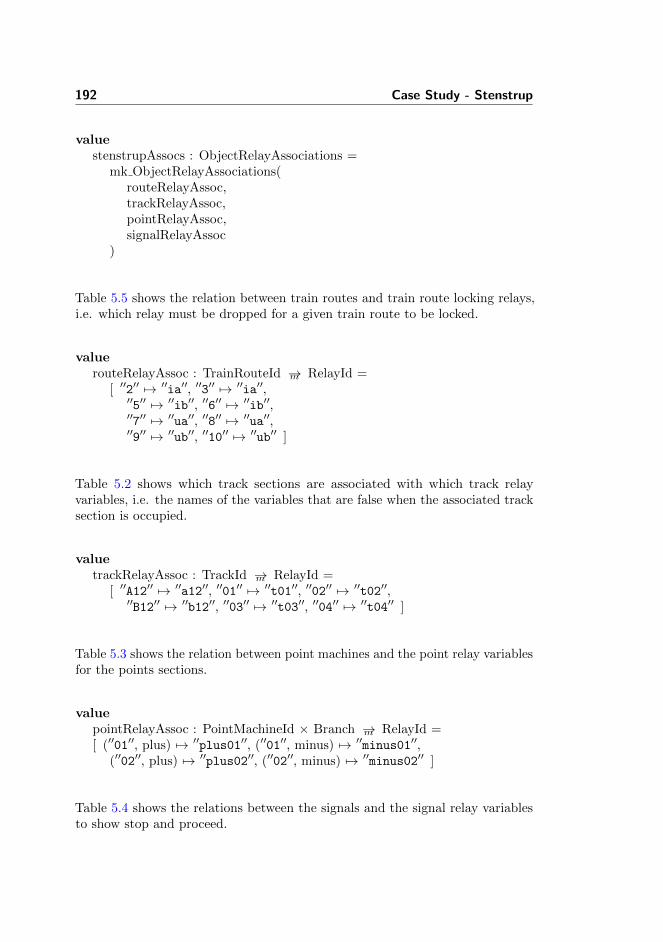
192 Case Study - Stenstrup
valuestenstrupAssocs : ObjectRelayAssociations =
mk ObjectRelayAssociations(routeRelayAssoc,trackRelayAssoc,pointRelayAssoc,signalRelayAssoc
)
Table 5.5 shows the relation between train routes and train route locking relays,i.e. which relay must be dropped for a given train route to be locked.
valuerouteRelayAssoc : TrainRouteId →m RelayId =
[ ′′2′′ 7→ ′′ia′′, ′′3′′ 7→ ′′ia′′,′′5′′ 7→ ′′ib′′, ′′6′′ 7→ ′′ib′′,′′7′′ 7→ ′′ua′′, ′′8′′ 7→ ′′ua′′,′′9′′ 7→ ′′ub′′, ′′10′′ 7→ ′′ub′′ ]
Table 5.2 shows which track sections are associated with which track relayvariables, i.e. the names of the variables that are false when the associated tracksection is occupied.
valuetrackRelayAssoc : TrackId →m RelayId =
[ ′′A12′′ 7→ ′′a12′′, ′′01′′ 7→ ′′t01′′, ′′02′′ 7→ ′′t02′′,′′B12′′ 7→ ′′b12′′, ′′03′′ 7→ ′′t03′′, ′′04′′ 7→ ′′t04′′ ]
Table 5.3 shows the relation between point machines and the point relay variablesfor the points sections.
valuepointRelayAssoc : PointMachineId × Branch →m RelayId =[ (′′01′′, plus) 7→ ′′plus01′′, (′′01′′, minus) 7→ ′′minus01′′,
(′′02′′, plus) 7→ ′′plus02′′, (′′02′′, minus) 7→ ′′minus02′′ ]
Table 5.4 shows the relations between the signals and the signal relay variablesto show stop and proceed.

13.2 Generating Model of External Events 193
valuesignalRelayAssoc : SignalId × Aspect →m RelayId =
[ (′′A′′, gr) 7→ ′′aGreen′′, (′′A′′, re) 7→ ′′aRed′′,(′′B′′, gr) 7→ ′′bGreen′′, (′′B′′, re) 7→ ′′bRed′′,(′′E′′, gr) 7→ ′′eGreen′′, (′′E′′, re) 7→ ′′eRed′′,(′′F′′, gr) 7→ ′′fGreen′′, (′′F′′, re) 7→ ′′fRed′′,(′′G′′, gr) 7→ ′′gGreen′′, (′′G′′, re) 7→ ′′gRed′′,(′′H′′, gr) 7→ ′′hGreen′′, (′′H′′, re) 7→ ′′hRed′′ ]
13.1.5 Buttons
The buttons are stored in the set allButtons. Table 5.5 shows the buttonidentifiers.
valueallButtons : Text-set = {′′b00406′′, ′′b03106′′, ′′b00606′′, ′′b03306′′}
13.2 Generating Model of External Events
The model of the external behaviour is generated by first translating the RSLspecification of the tool to SML and then calling the generators generate function.
test case[ generate transitionSystem ]
print(generate(′′InterlockingSystem′′,stenstrupAssocs,stenstrupIP,allButtons))
13.2.1 Result
The generator creates a transition system containing 24 variables, 47 transitionsand 102 assertions. The entire unparsed output is available in appendix F.1.
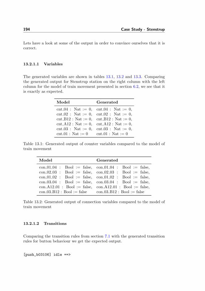
194 Case Study - Stenstrup
Lets have a look at some of the output in order to convince ourselves that it iscorrect.
13.2.1.1 Variables
The generated variables are shown in tables 13.1, 13.2 and 13.3. Comparingthe generated output for Stenstrup station on the right column with the leftcolumn for the model of train movement presented in section 6.2, we see that itis exactly as expected.
Model Generated
cnt 04 : Nat := 0,cnt 02 : Nat := 0,cnt B12 : Nat := 0,cnt A12 : Nat := 0,cnt 03 : Nat := 0,cnt 01 : Nat := 0
cnt 04 : Nat := 0,cnt 02 : Nat := 0,cnt B12 : Nat := 0,cnt A12 : Nat := 0,cnt 03 : Nat := 0,cnt 01 : Nat := 0
Table 13.1: Generated output of counter variables compared to the model oftrain movement
Model Generated
con 01 04 : Bool := false,con 02 03 : Bool := false,con 01 02 : Bool := false,con 03 04 : Bool := false,con A12 01 : Bool := false,con 03 B12 : Bool := false
con 01 04 : Bool := false,con 02 03 : Bool := false,con 01 02 : Bool := false,con 03 04 : Bool := false,con A12 01 : Bool := false,con 03 B12 : Bool := false
Table 13.2: Generated output of connection variables compared to the model oftrain movement
13.2.1.2 Transitions
Comparing the transition rules from section 7.1 with the generated transitionrules for button behaviour we get the expected output.
[push_b03106] idle ==>

13.2 Generating Model of External Events 195
Model Generated
fwd 04 : Bool := false, bwd 04: Bool := false, fwd 02 :Bool := false, bwd 02 : Bool:= false, fwd B12 : Bool:= false, bwd B12 : Bool:= false, fwd A12 : Bool :=false, bwd A12 : Bool := false,fwd 03 : Bool := false, bwd 03: Bool := false, fwd 01 : Bool:= false, bwd 01 : Bool :=false
fwd 04 : Bool := false, bwd 04: Bool := false, fwd 02 :Bool := false, bwd 02 : Bool:= false, fwd B12 : Bool:= false, bwd B12 : Bool:= false, fwd A12 : Bool :=false, bwd A12 : Bool := false,fwd 03 : Bool := false, bwd 03: Bool := false, fwd 01 : Bool:= false, bwd 01 : Bool :=false
Table 13.3: Generated output of direction variables compared to the model oftrain movement
b03106’ = true, idle’ = false
[=]
[push_b00606] idle ==>
b00606’ = true, idle’ = false
[=]
[push_b00406] idle ==>
b00406’ = true, idle’ = false
[=]
[push_b03306] idle ==>
b03306’ = true, idle’ = false
Again, comparing the transition rules presented in section 7.2 with the generatedoutput we get the expected output.
[point01FromPlus] idle /\ ib /\ plus01 /\ ua /\ t01 /\ ia ==>
plus01’ = false, idle’ = false
[=]
[point01ToPlus] idle /\ ib /\ ~(plus01) /\ ua /\ ~(minus01) /\
ia /\ t01 ==>
plus01’ = true, idle’ = false
[=]
[point01FromMinus] idle /\ ib /\ minus01 /\ ua /\ t01 /\ ia ==>
minus01’ = false, idle’ = false
[=]
[point01ToMinus] idle /\ ib /\ ~(plus01) /\ ua /\ ~(minus01) /\

196 Case Study - Stenstrup
ia /\ t01 ==>
minus01’ = true, idle’ = false
Comparing an entering rule and a leaving rule from section 6.3.1 and 6.3.3 withthe generated output we get the expected result.
[enter_A12_from_line] idle /\ aGreen /\ ~(aRed) ==>
fwd_A12’ = true, idle’ = false, a12’ = false,
cnt_A12’ = cnt_A12 + 1
[=]
[leave_A12_to_line] bwd_A12 /\ idle /\ ~(con_A12_01) /\
cnt_A12 = 1 ==>
idle’ = false, cnt_A12’ = 0, a12’ = true, bwd_A12’ = false
13.2.1.3 Assertions
Finally, comparing one of the assertions presented in section 10.8 with thegenerated output below we get the expected result.
[train_route_release_2] InterlockingSystem |- G(ia /\ X(plus02 /\
plus01 /\ ~(ia) /\ F(ia)) => X(U(~(ia), ~(t01) /\ t02 /\ ~(ia)
/\ X(U(~(ia), ~(ia) /\ ~(t02) /\ t01)))))
13.3 Combining the Models
We now have the RSL-SAL model of the external system. This needs to becombined with the internal system into a single model, that can then be modelchecked.
The model of the internal system is acquired, as described in the user guidefound in appendix C, by using the tool developed by Kjær and Le Bliguet [2].
The combined RSL-SAL model of the internal and external system can then betranslated to SAL, and finally model checked. The results of model checkingStenstrup station will be presented in the next section.

13.4 Results Stenstrup 197
13.4 Results Stenstrup
The result shows that the consistency conditions are satisfied. This means thatthe internal system responds according to the external events provided by themodel of train movement. Since the safety properties (chapter 10) are satisfiedas well, we can conclude that the model of the interlocking system ensures thesafety of the modelled train movements (chapter 6).
The results of the model checker can be found in appendix F.2. All the inter-model consistency and safety property assertions were satisfied including theassertions provided by Kjær and Le Bliguet [2]
The model checking was conducted on the following hardware which took ap-proximately 1.5 hour.
CPU Intel Core i5-2400 CPU @ 3.10 GHz, 6MB cache
RAM 8 GB 1333 MHz DDR3 non-ECC SDRAM
Operating System Xubuntu 11.04, Linux kernel 2.6.38-13-generic-pae
RSLTC Version 2.5-1
SAL Version 3.0

198 Case Study - Stenstrup

Chapter 14
Conclusion
Banedanmark wanted to automate the process of validating relay interlockingsystems. Some work had already been carried out, but part of the generationprocess was still to be done manually.
In this project we have specified data models of station layout diagrams, trainroute tables and the RSL-SAL transition system, and created well-formednessfunctions that essentially acts as data validators. Furthermore, we createdassociations between the physical station elements and the model of the internalsystem, and associations to allow the generation of a representation of trains.
We have, in RSL, specified a tool which is able to generate a behavioural modelof train movements and the behaviour of operating points and buttons forStenstrup station. We then formalised basic safety properties, identified safetyproperties from a train route table and specified a generator that can generatethese properties automatically. Our model of train movement is compatible withKjær and Le Bliguet’s [2] model of the internal system and is indeed intended tobe a substitute for the train movement model they suggested.
To verify the compatibility between the model of train movement and internalsystem we identified, formalised and generated inter-model consistency conditionsto ensure that the external behaviours were observed by the internal system.

200 Conclusion
Thus, the tool is capable of generating a RSL-SAL transition system of theexternal events from station documentation using our data models, in additionto generating the safety and consistency assertions.
With our contribution Banedanmark now has a functioning prototype for auto-mated validation of relay interlocking systems. With such a tool Banedanmarkcan validate their station documentation faster and eliminate the risk of humanerror. Furthermore, one can speculate that the proposed tool would verify moreproperties, compared to now.
Our model of train movements allows for trains of arbitrary length and usesimplicitly defined trains, which allows for an arbitrary number of trains on thestation. This model was chosen over a model using explicitly defined trains, asthat model was not only limited to a certain number of trains, but also modelchecked slower, which could cause problems for larger systems.
Finally, we model checked a combined RSL-SAL transition system of the externalevents and the internal events. The result of our case study of Stenstrup stationshowed that all safety and consistency conditions were satisfied using our model oftrain movement. From this fact we concluded that the model of the interlockingsystem ensures the safety of the modelled train movements.
We are aware that the algorithm for assigning directions may not functionproperly if more than one track is connected to the line at each end. This couldbe solved by differentiating between the line sections at each end.
RSL-SAL
Station Documentation
Station Layout
Train Route Table Auto Generation
Internal BehaviourConfidence Conditions
External Behaviour
Safety Properties
Translation to SAL SAL files
SAL Model Checker
Results
Auto Generation
Auto Generation
Figure 14.1: Auto generation of external behaviour and safety properties.

14.1 Future Work 201
14.1 Future Work
In this section, suggestions will be made on how to proceed from here and howthe developed tool and the tools used can be improved.
14.1.1 Directly Related
While the tool has been tested on Stenstrup, it is not known how well it workwith another station using the DSB type 1954 relay interlocking system. Theproblem with testing this, is the amount of work needed to transform the physicaldocumentation into the digital data structure. This is especially true consideringthe assumptions made in both this work and that of Kjær and Le Bliguet [2].
A graphical editor would help speed up this process. Unfortunately the outputof the editor developed by Eriksen and Pedersen [7] is not compatible with toolset.
If the tool set should see use in industry, it would most likely have to be expandedwith some of the parts that where not considered due to scope, e.g. support forlevel crossings.
Finally, some work would be required to fully automate the verification process.As of now, the model of the internal and the external system has to be combinedby hand before the combined system can be given to the model checker. Onecould choose to expand the Java implementation of the generator of the internalsystem, using our specification of the external system. However, it would seemmore natural to merge the specifications, make the specification of the internalsystem executable and combine it with ours at this level. By making the completespecification executable, the output of the complete system can be tested beforeimplementation.
14.1.2 Indirectly Related
During this work, we found that it would be useful for RSL-SAL to supportmultiple models in a single file.
scheme SchemeName =class

202 Conclusion
transition system [ Internal ]local...in...end
transition system [ External ]local...in...end
end
This would greatly improve the readability of the file, as the parts would belogically divided.
Even if SAL does not support interaction between two models, the RSL-SALtranslator could combine them into a single SAL model. Any conflicting namescould be solved by adding the system name to the conflicting variable or transitionname.

Bibliography
[1] RAISE Tools. Home page: http://www.iist.unu.edu/newrh/III/3/1/
page.html.
[2] Andreas Andersen Kjær and Marie Le Bliguet. Modelling InterlockingSystem for Railway Stations. Master’s thesis, DTU, 2008.
[3] Christel Baier and Joost-Pieter Katoen. Principles of Model Checking. MITPress, 2008.
[4] Banedanmark. Functional Safety Requirements Version 1.1 Issue 1.3.Internal Banedanmark Publication, September 2003.
[5] Banedanmark. Sikkerhedsreglement af 1975 (SR). Banedanmark,2008. Available as PDF from http://www.bane.dk/hentmedie.asp?
filID=11350 (Danish).
[6] Leonardo de Moura, Sam Owre, and Natarajan Shankar. The SAL LanguageManual. Technical Report SRI-CSL-01-02, SRI International.
[7] Louise Elmose Eriksen and Boe Pedersen. Simulation of Relay InterlockingSystems. Bachelor thesis, DTU, 2007.
[8] RAISE Language Group. The RAISE Specification Language. Prentice-Hall,1 edition, 1992.
[9] Anne Elisabeth Haxthausen. Towards a Framework for Modelling andVerification of Relay Interlocking Systems. In Modelling Development andVerification of Adaptive Systems, pages 101–111, 2010.
204 BIBLIOGRAPHY
[10] Henrik W. Karlsson and Carsten S. Lundsten. Introduktion til sikrings- ogfjernstyringsanlæg. Rambøll, 2006. (Danish).
[11] Juan Ignacio Perna and Chris George. Model Checking RAISE Specifications.Technical Report 331, UNU-IIST, 2006.
[12] Gregor Theeg and Sergej Vlasenko. Railway Signalling & Interlocking.DVV Media Group — Eurailpress, 1 edition, 2009.

Appendix A
Word List
The table below has a translation from english to danish of the words andterminology used throughout this thesis.

206 Word List
English Danish
(Track) Section Sporafsnit(Set of) Points SporskifteBranch ForgreningRelay RelæSignal lamp relay LampekontrolrelæPoint relay SporskiftekontrolrelæInterlocking System SikringsanlægTrain route TogvejTrain route table TogvejstabelInterlocking Plan SikringsplanShunting movement RangeringOpen Line Fri baneLine block LinieblokDistant signal Fremskudt signal(Station) Entry signal Indkørelsessignal(Station) Pre-exit signal Perronudkørelsessignal(Station) Exit signal UdkørelsessignalShunt signal Signal for rangeringStation limit StationsgrænseSignal Release Stop Fald

Appendix B
Documentation of StenstrupStation

208 Documentation of Stenstrup Station
Fig
ure
B.1
:S
tati
on
Lay
ou
tD
iagra
mof
Ste
nst
rup
Sta
tion
.
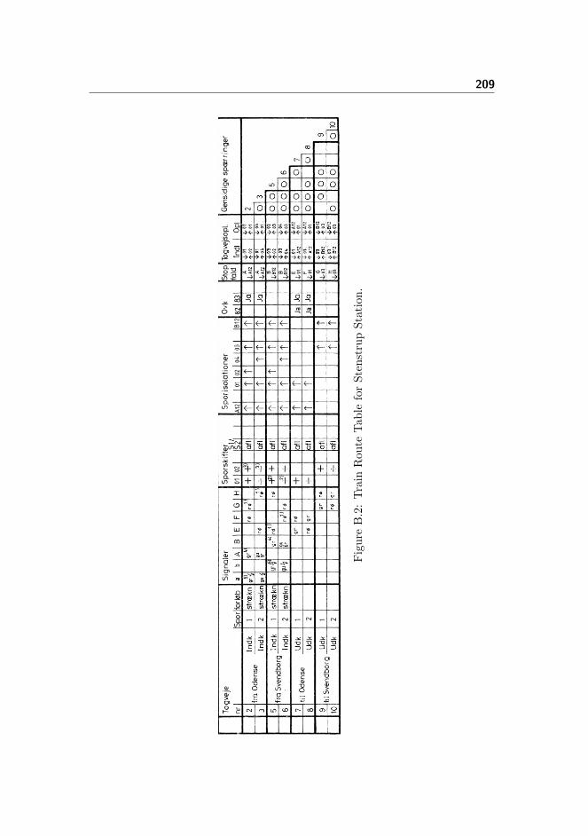
209
Fig
ure
B.2
:T
rain
Rou
teT
ab
lefo
rS
ten
stru
pS
tati
on
.
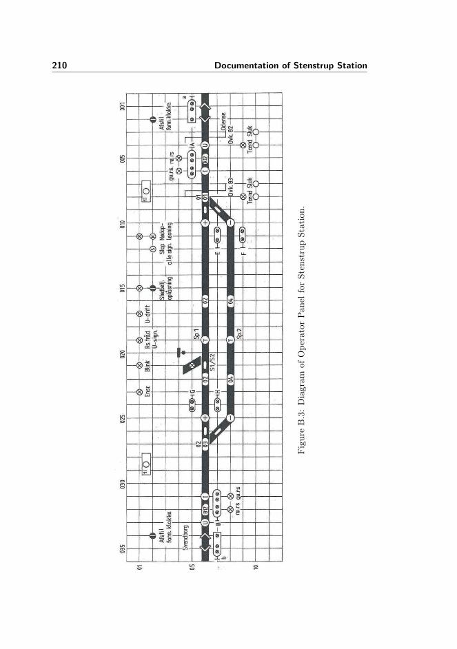
210 Documentation of Stenstrup Station
Fig
ure
B.3
:D
iagra
mof
Op
erato
rP
an
elfo
rS
ten
stru
pS
tati
on
.
Appendix C
User Guide
The following section will describe how to use the tool.
C.1 Requirements
Ensure that the following software is installed and running correctly:
• rsltc version 2.5
• Standard ML of New Jersey v110.72
• SAL 3.0
• Java Runtime Environment 6 (1.6)
• Emacs 23
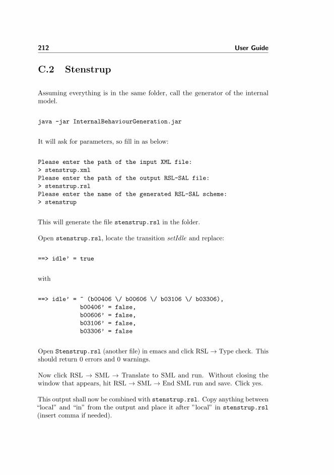
212 User Guide
C.2 Stenstrup
Assuming everything is in the same folder, call the generator of the internalmodel.
java -jar InternalBehaviourGeneration.jar
It will ask for parameters, so fill in as below:
Please enter the path of the input XML file:
> stenstrup.xml
Please enter the path of the output RSL-SAL file:
> stenstrup.rsl
Please enter the name of the generated RSL-SAL scheme:
> stenstrup
This will generate the file stenstrup.rsl in the folder.
Open stenstrup.rsl, locate the transition setIdle and replace:
==> idle’ = true
with
==> idle’ = ~ (b00406 \/ b00606 \/ b03106 \/ b03306),
b00406’ = false,
b00606’ = false,
b03106’ = false,
b03306’ = false
Open Stenstrup.rsl (another file) in emacs and click RSL→ Type check. Thisshould return 0 errors and 0 warnings.
Now click RSL → SML → Translate to SML and run. Without closing thewindow that appears, hit RSL → SML → End SML run and save. Click yes.
This output shall now be combined with stenstrup.rsl. Copy anything between“local” and “in” from the output and place it after ”local” in stenstrup.rsl
(insert comma if needed).

Stenstrup 213
Next copy everything between “in” and “end” from the output and place it after”in” in stenstrup.rsl (insert [=] if needed).
Finally copy everything after ”ltl assertion” from the output and paste it in after”ltl assertion” in stenstrup.rsl and type check stenstrup.rsl. This shouldreturn no errors and no warnings.
Close the output buffer and Stenstrup.rsl, leaving just stenstrup.rsl open.Click RSL → SAL → Translate to SAL. This will generate a great number offiles. Next click RSL → SAL → Run SAL well-formed checker. All three checksshould be successful.
Finally click RSL → SAL → Run model checker → base. Hit enter. Expect themodel to run for at least 1.5 hour.

214 User Guide

Appendix D
Behavioural Model of TrainMovements Using Explicitly
Defined Trains
This solution explores explicit declaration of trains. A train occupies a numberof connected track sections and has a direction. Here the tracks occupied bythe train is collected in a set1 and the direction is a pointer to the next section.Alternatively a up/down type mechanism could be employed.
transition system [ InterlockingSystem ]local
...train1dir : TrackId := none,train1loc : TrackId-set := {},
in...
end
1Using RSL-SAL, a set is translated into a boolean variable for each possible element inthe set, which is true if the element is in the set. Not all RSL set operators are translatable,unfortunately, most noticeable card, which would actually be easy to implement, but that isan aside.

216 Behavioural Model of Train Movements Using Explicitly Defined Trains
where TrackId is defined as follows
type TrackId ==t a12 | t 01 | t 02 | t 03 | t 04 | t b12 | none
The initial state of the system is the normal state. Here no track sections areoccupied and therefore, no trains are at the station. Hence the direction isinitialised to none (could be set to either a12 or b12, but is not, since we don’twant to dictate its entrance.) and the location is the empty set to represent thatthe train is not at the station.
It is assumed that the trains respect the aspects of the signals. Therefore notrain are supposed to enter the station before a green light at a station entrysignal is given. Assuming a working and well-formed interlocking system, thisonly happens once a route has been locked. This require an external event, whichwe assumed has happened in the following. Every rule also require the system tobe idle, so that the relays are in a correct position. As a consequence every ruleintroduced here will also set the system in the busy state, to allow the relays toresponse to the external events.
D.1 Enter
Lets look at the rules for entering the station at section a12.
[ t1 enter a12 from line ]idle ∧ aGreen ∧ train1loc = {} −→
idle′ = false,a12′ = false,train1dir′ = t 01,train1loc′ = train1loc ∪ {t a12}
The guard require the station entry signal to show green, while the train cannotalready be at the station. If these conditions are met, the train is allowed toenter a12. Therefore the relay a12 is dropped, the track identifier is added tothe location set and the direction is set to section 01, since the train came fromthe line. This information is derived from the station layout.

Enter 217
Entering the station is a special case and therefore has rules that are not in thegeneral case. Lets look at another special case, which happens to be the next inour scenario.
[ t1 enter 01 in plus from a12 ]idle ∧ train1dir = t 01 ∧ t a12 ∈ train1loc ∧ plus01 −→
idle′ = false,t01′ = false,train1dir′ = t 02,train1loc′ = train1loc ∪ {t 01}
In this situation the train enters 01 from a12. For this to occur, we need tohave a train on a12, which is headed towards 01. Since the direction points to aspecific section, a rule is needed for each possible state of the point. Here it isin plus. Therefore the next section will be 02. Had it been in minus, the nextwould be 04 and if the point is not locked, the train will derail, so the directionis set to none.
[ t1 enter 01 in neither ]idle ∧ train1dir = t 01 ∧ ∼ plus01 ∧ ∼ minus01 −→
idle′ = false,t01′ = false,train1dir′ = none,train1loc′ = train1loc ∪ {t 01}
The interlocking system should ensure that both the plus and minus relay cannotbe dawn at the same time, eliminating the case where the point is locked in bothplus and minus position, which also happens to be physically impossible.
Lets continue the example. If 01 was in plus, the next section would be 02. 02 isa regular track segment, but since the trains comes from a point, we again needto ensure that the point is in the correct position.
[ t1 enter 02 from 01 ]idle ∧ train1dir = t 02 ∧t 01 ∈ train1loc ∧ plus01 −→
idle′ = false,t02′ = false,train1dir′ = t 03,train1loc′ = train1loc ∪ {t 02}
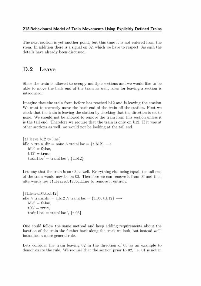
218 Behavioural Model of Train Movements Using Explicitly Defined Trains
The next section is yet another point, but this time it is not entered from thestem. In addition there is a signal on 02, which we have to respect. As such thedetails have already been discussed.
D.2 Leave
Since the train is allowed to occupy multiple sections and we would like to beable to move the back end of the train as well, rules for leaving a section isintroduced.
Imagine that the train from before has reached b12 and is leaving the station.We want to correctly move the back end of the train off the station. First wecheck that the train is leaving the station by checking that the direction is set tonone. We should not be allowed to remove the train from this section unless itis the tail end. Therefore we require that the train is only on b12. If it was atother sections as well, we would not be looking at the tail end.
[ t1 leave b12 to line ]idle ∧ train1dir = none ∧ train1loc = {t b12} −→
idle′ = false,b12′ = true,train1loc′ = train1loc \ {t b12}
Lets say that the train is on 03 as well. Everything else being equal, the tail endof the train would now be on 03. Therefore we can remove it from 03 and thenafterwards use t1 leave b12 to line to remove it entirely.
[ t1 leave 03 to b12 ]idle ∧ train1dir = t b12 ∧ train1loc = {t 03, t b12} −→
idle′ = false,t03′ = true,train1loc′ = train1loc \ {t 03}
One could follow the same method and keep adding requirements about thelocation of the train the further back along the track we look, but instead we’llintroduce a more general rule.
Lets consider the train leaving 02 in the direction of 03 as an example todemonstrate the rule. We require that the section prior to 02, i.e. 01 is not in

Leave 219
the location set. This ensures that we do not split the train. In addition, it isrequired that the train is on both 02 and 03. The reason for this is that wecannot remove a train from a section where it is not located and we should notremove the entire train, just the tail end. If the train was positioned on just 02and we did not require it to be on 03 as well, both the head and tail end wouldbe at 02 and therefore we would remove the entire train. Obviously a train isnot allowed to disappear at random locations.
[ t1 leave 02 to 03 ]idle ∧ ∼ (t 01 ∈ train1loc) ∧{t 02, t 03} ⊆ train1loc ∧ train1dir 6= t 01 −→
idle′ = false,t02′ = true,train1loc′ = train1loc \ {t 02}

220 Behavioural Model of Train Movements Using Explicitly Defined Trains

Appendix E
Specifications
E.1 Data Models
E.1.1 Objects
context: InterlockingPlanobject IP : InterlockingPlan
context: StationLayoutobject SL : StationLayout
context: TrainRouteTableobject TRT : TrainRouteTable
context: TransitionSystemobject TS : TransitionSystem
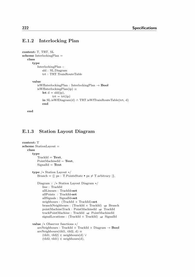
222 Specifications
E.1.2 Interlocking Plan
context: T, TRT, SLscheme InterlockingPlan =
classtype
InterlockingPlan ::sld : SL.Diagramtrt : TRT.TrainRouteTable
valueisWfInterlockingPlan : InterlockingPlan → BoolisWfInterlockingPlan(ip) ≡
let d = sld(ip),trt = trt(ip)
in SL.isWfDiagram(d) ∧ TRT.isWfTrainRouteTable(trt, d)end
end
E.1.3 Station Layout Diagram
context: Tscheme StationLayout =
classtype
TrackId = Text,PointMachineId = Text,SignalId = Text
type /∗ Station Layout ∗/Branch = {| ps : T.PointsState • ps 6= T.arbitrary |},
Diagram :: /∗ Station Layout Diagram ∗/line : TrackIdallLinears : TrackId-setallPoints : TrackId-setallSignals : SignalId-setneighbours : (TrackId × TrackId)-setbranchNeighbours : (TrackId × TrackId) →m BranchpointMachineTrack : PointMachineId →m TrackIdtrackPointMachine : TrackId →m PointMachineIdsignalLocations : (TrackId × TrackId) →m SignalId
value /∗ Observer functions ∗/areNeighbours : TrackId × TrackId × Diagram → BoolareNeighbours(tId1, tId2, d) ≡
(tId1, tId2) ∈ neighbours(d) ∨(tId2, tId1) ∈ neighbours(d),
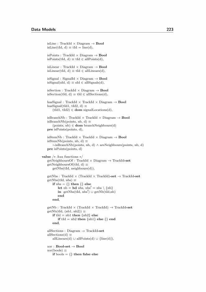
Data Models 223
isLine : TrackId × Diagram → BoolisLine(tId, d) ≡ tId = line(d),
isPoints : TrackId × Diagram → BoolisPoints(tId, d) ≡ tId ∈ allPoints(d),
isLinear : TrackId × Diagram → BoolisLinear(tId, d) ≡ tId ∈ allLinears(d),
isSignal : SignalId × Diagram → BoolisSignal(sId, d) ≡ sId ∈ allSignals(d),
isSection : TrackId × Diagram → BoolisSection(tId, d) ≡ tId ∈ allSections(d),
hasSignal : TrackId × TrackId × Diagram → BoolhasSignal(tId1, tId2, d) ≡
(tId1, tId2) ∈ dom signalLocations(d),
isBranchNb : TrackId × TrackId × Diagram → BoolisBranchNb(points, nb, d) ≡
(points, nb) ∈ dom branchNeighbours(d)pre isPoints(points, d),
isStemNb : TrackId × TrackId × Diagram → BoolisStemNb(points, nb, d) ≡∼isBranchNb(points, nb, d) ∧ areNeighbours(points, nb, d)
pre isPoints(points, d)
value /∗ Aux functions ∗/getNeighboursOf : TrackId × Diagram → TrackId-setgetNeighboursOf(tId, d) ≡
getNbs(tId, neighbours(d)),
getNbs : TrackId × (TrackId × TrackId)-set → TrackId-setgetNbs(tId, nbs) ≡
if nbs = {} then {} elselet nb = hd nbs, nbs′ = nbs \ {nb}in getNbs(tId, nbs′) ∪ getNb(tId,nb)end
end,
getNb : TrackId × (TrackId × TrackId) → TrackId-setgetNb(tId, (nb1, nb2)) ≡
if tId = nb1 then {nb2} elseif tId = nb2 then {nb1} else {} end
end,
allSections : Diagram → TrackId-setallSections(d) ≡
allLinears(d) ∪ allPoints(d) ∪ {line(d)},
xor : Bool-set → Boolxor(bools) ≡
if bools = {} then false else

224 Specifications
let bool = hd bools, bools′ = bools \ {bool}in xor(bool, xor(bools′))end
end,
xor : Bool × Bool → Boolxor(p, q) ≡ (p ∧ ∼q) ∨ (∼p ∧ q)
value /∗ Well−formedness ∗/isWfDiagram : Diagram → BoolisWfDiagram(d) ≡
isWfIdentifiers(d) ∧isWfNeighbours(d) ∧isWfBranchNeighbours(d) ∧isWfPointMachines(d) ∧isWfSignalLocations(d),
isWfIdentifiers : Diagram → BoolisWfIdentifiers(d) ≡
allLinears(d) ∩ allPoints(d) = {}
value /∗ Well−formedness neighbours ∗/isWfNeighbours : Diagram → BoolisWfNeighbours(d) ≡
neighbours OnlySections(d) ∧neighbours EverySection(d) ∧neighbours Irreflexive(d) ∧neighbours Antisymmetrical(d) ∧linears 1or2Neighbours(d) ∧points 3Neighbours(d) ∧pointsNotNeighbours(d),
neighbours OnlySections : Diagram → Boolneighbours OnlySections(d) ≡
( ∀ (tId1, tId2) : TrackId × TrackId •
(tId1, tId2) ∈ neighbours(d) ⇒isSection(tId1, d) ∧ isSection(tId2, d) ),
neighbours EverySection : Diagram → Boolneighbours EverySection(d) ≡
( ∀ tId : TrackId • tId ∈ allSections(d) ⇒( ∃ nb : TrackId • nb ∈ allSections(d) ∧
areNeighbours(tId, nb, d)) ),
neighbours Irreflexive : Diagram → Boolneighbours Irreflexive(d) ≡
( ∀ (tId1, tId2) : TrackId × TrackId •
(tId1, tId2) ∈ neighbours(d) ⇒tId1 6= tId2 ),
neighbours Antisymmetrical : Diagram → Boolneighbours Antisymmetrical(d) ≡
( ∀ (tId1, tId2) : TrackId × TrackId •
(tId1, tId2) ∈ neighbours(d) ⇒(tId2, tId1) 6∈ neighbours(d) ),

Data Models 225
linears 1or2Neighbours : Diagram → Boollinears 1or2Neighbours(d) ≡
( ∀ tId : TrackId •
tId ∈ allLinears(d) ⇒let n = card getNeighboursOf(tId, d) in
n ≥ 1 ∧ n ≤ 2end),
points 3Neighbours : Diagram → Boolpoints 3Neighbours(d) ≡
( ∀ tId : TrackId •
tId ∈ allPoints(d) ⇒card getNeighboursOf(tId, d) = 3),
pointsNotNeighbours : Diagram → BoolpointsNotNeighbours(d) ≡∼( ∃ (tId1, tId2) : TrackId × TrackId •
(tId1, tId2) ∈ neighbours(d) ∧isPoints(tId1, d) ∧ isPoints(tId2, d) )
value /∗ Well−formedness branchNeighbours ∗/isWfBranchNeighbours : Diagram → BoolisWfBranchNeighbours(d) ≡
branchNeighbours areNeighbours(d) ∧branchNeighbours FirstIsPoints(d) ∧branchNeighbours everyPoints 2branchNbs(d) ∧branchNeighbours diffNbsOnBranch(d),
branchNeighbours areNeighbours : Diagram → BoolbranchNeighbours areNeighbours(d) ≡
( ∀ (tId1, tId2) : (TrackId × TrackId) •
(tId1, tId2) ∈ dom branchNeighbours(d) ⇒areNeighbours(tId1, tId2, d) ),
branchNeighbours FirstIsPoints : Diagram → BoolbranchNeighbours FirstIsPoints(d) ≡
( ∀ (tId1, tId2) : TrackId × TrackId •
(tId1, tId2) ∈ dom branchNeighbours(d) ⇒isPoints(tId1,d)
),
branchNeighbours everyPoints 2branchNbs : Diagram → BoolbranchNeighbours everyPoints 2branchNbs(d) ≡
(∀ p : TrackId • p ∈ allPoints(d) ⇒(∃ (tId1, tId2) : TrackId × TrackId •
(tId1, tId2) ∈ dom branchNeighbours(d) ∧p = tId1 ∧(∃ (tId1′, tId2′) : TrackId × TrackId •
(tId1′, tId2′) ∈ dom branchNeighbours(d) ∧p = tId1′ ∧ tId2 6= tId2′)
)),
branchNeighbours diffNbsOnBranch : Diagram → Bool

226 Specifications
branchNeighbours diffNbsOnBranch(d) ≡(∀ (p, tId1) : TrackId × TrackId •
(p, tId1) ∈ branchNeighbours(d) ⇒(∀ (p′, tId2) : TrackId × TrackId •
(p′, tId2) ∈ branchNeighbours(d) ⇒(p = p′ ∧ tId1 6= tId2 ⇒
(branchNeighbours(d)(p, tId1) = T.plus ∧branchNeighbours(d)(p, tId2) = T.minus) ∨
(branchNeighbours(d)(p, tId1) = T.minus ∧branchNeighbours(d)(p, tId2) = T.plus))))
value /∗ Well−formnedness point machines ∗/isWfPointMachines : Diagram → BoolisWfPointMachines(d) ≡
areSymmetrical(pointMachineTrack(d), trackPointMachine(d)) ∧pointsSectionsExists(d),
areSymmetrical : (PointMachineId →m TrackId) ×(TrackId →m PointMachineId) → Bool
areSymmetrical(pmt, tpm) ≡dom pmt = rng tpm ∧dom tpm = rng pmt ∧( ∀ pmId : PointMachineId • pmId ∈ dom pmt ⇒
let tId = pmt(pmId)in pmId = tpm(tId)end ) ∧
( ∀ tId : TrackId • tId ∈ dom tpm ⇒let pmId = tpm(tId)in tId = pmt(pmId)end ),
pointsSectionsExists : Diagram → BoolpointsSectionsExists(d) ≡
dom trackPointMachine(d) = allPoints(d)
value /∗ Well−formedness signalLocations ∗/isWfSignalLocations : Diagram → BoolisWfSignalLocations(d) ≡
signalLocation UsesExistingSignals(d) ∧signalsArePlacedAtValtIdNeighbours(d),
signalLocation UsesExistingSignals : Diagram → BoolsignalLocation UsesExistingSignals(d) ≡
rng signalLocations(d) = allSignals(d),
signalsArePlacedAtValtIdNeighbours : Diagram → BoolsignalsArePlacedAtValtIdNeighbours(d) ≡( ∀ (tId1, tId2) : (TrackId × TrackId) •
(tId1, tId2) ∈ dom signalLocations(d) ⇒areNeighbours(tId1, tId2, d) )
end

Data Models 227
E.1.4 Train Route Table
context: T, SLscheme TrainRouteTable =
classtype
RelayState == drawn | dropped,Aspect == gr | re | arbitrary,
ReleaseCond = (SL.TrackId × RelayState) × (SL.TrackId × RelayState),ReleaseSequence = ReleaseCond × ReleaseCond, - - Indl ¿¡ Opl
DataRow ::overlap : SL.TrackId-setsignals : SL.SignalId →m Aspectpoints : SL.PointMachineId →m T.PointsStatetrainDetection : SL.TrackId →m BoolsignalRelease : SL.SignalId × SL.TrackIdtrainRouteRelease : ReleaseSequencemutuallyBlocking : T.TrainRouteId →m Bool,
TrainRouteTable = T.TrainRouteId →m DataRow
value - - AUXgetEntrySignal : DataRow → SL.SignalIdgetEntrySignal(dr) ≡
let (sId, tId) = signalRelease(dr) in sId end,
coveredSections : (SL.TrackId →m Bool) → SL.TrackId-setcoveredSections(trainDetection) ≡{ tId | tId : SL.TrackId • tId ∈ dom trainDetection ∧
trainDetection(tId)},
areConnected : SL.TrackId-set × SL.Diagram → BoolareConnected(sections, d) ≡
if sections = {} then true elselet s = hd sections, sections′ = sections \ {s}in findConnected({s}, {s}, sections, d) = sectionsend
end,
findConnected : SL.TrackId-set × SL.TrackId-set ×SL.TrackId-set × SL.Diagram → SL.TrackId-set
findConnected(queue, visited, sectionsInRoute, d) ≡if queue = {} then visited else
let q = hd queue,nbs = SL.getNeighboursOf(q, d) ∩ sectionsInRoute,queue′ = (queue \ {q}) ∪ (nbs \ visited),visited′ = visited ∪ {q}
in findConnected(queue′, visited′, sectionsInRoute, d)end
end
value - - Well-formedness

228 Specifications
isWfTrainRouteTable : TrainRouteTable × SL.Diagram → BoolisWfTrainRouteTable(trt, d) ≡
(∀ trId : T.TrainRouteId • trId ∈ dom trt ⇒isWfDataRow(trId, d, trt)),
isWfDataRow : T.TrainRouteId × SL.Diagram × TrainRouteTable → BoolisWfDataRow(trId, d, trt) ≡
let dr = trt(trId)in isWfOverlap(dr, d) ∧
isWfSignals(dr, d) ∧isWfPoints(dr, d) ∧isWfTrainDetection(trainDetection(dr), d) ∧isWfSignalRelease(signalRelease(dr), d) ∧isWfTrainRouteRelease(dr, d) ∧isWfMutuallyBlocking(trId, trt)
end
value - - Well-formedness of overlapisWfOverlap : DataRow × SL.Diagram → BoolisWfOverlap(dr, d) ≡
let overlap = overlap(dr)in card overlap > 0 ⇒
overlapCovered(overlap, trainDetection(dr)) ∧overlapIsConnected(overlap, d) ∧endOfRoute(dr, d)
end,
- - 4.3.3.1.1overlapCovered : SL.TrackId-set × (SL.TrackId →m Bool) → BooloverlapCovered(overlap, trainDetection) ≡
overlap ⊆ coveredSections(trainDetection),
- - 4.3.3.1.2overlapIsConnected : SL.TrackId-set × SL.Diagram → BooloverlapIsConnected(overlap, d) ≡
areConnected(overlap, d),
- - 4.3.3.1.3endOfRoute : DataRow × SL.Diagram → BoolendOfRoute(dr, d) ≡
let overlap = overlap(dr),coveredSections = coveredSections(trainDetection(dr)),route = coveredSections \ overlap
in ( ∃! tId : SL.TrackId • tId ∈ overlap ∧let nbs = SL.getNeighboursOf(tId, d),
nbsInOverlap = nbs ∩ routein card nbsInOverlap ≥ 1end
)end
value - - Well-formedness of signalsisWfSignals : DataRow × SL.Diagram → BoolisWfSignals(dr, d) ≡
let signals = signals(dr)

Data Models 229
in existingSignals(signals, d) ∧proceedEntry(getEntrySignal(dr), signals)
end,
- - 4.3.4.1.1existingSignals : (SL.SignalId →m Aspect) × SL.Diagram → BoolexistingSignals(signals, d) ≡
dom signals = SL.allSignals(d),
- - 4.3.4.1.2proceedEntry : SL.SignalId × (SL.SignalId →m Aspect) → BoolproceedEntry(entrySignal, signals) ≡
signals(entrySignal) = gr
value - - Well-formedness of pointsisWfPoints : DataRow × SL.Diagram → BoolisWfPoints(dr, d) ≡
let points = points(dr)in - - 4.3.5.1.1
pointMachinesExist(dom points, d) ∧- - 4.3.5.1.2pointMachinesInTRT(dr, d) ∧- - 4.3.5.1.3pointsInRouteLocked(dr, d) ∧- - 4.3.5.1.4correctPos(dr, d)
end,
- - 4.3.5.1.1pointMachinesExist : SL.PointMachineId-set × SL.Diagram → BoolpointMachinesExist(points, d) ≡
( ∀ pId : SL.PointMachineId • pId ∈ points ⇒pId ∈ dom SL.pointMachineTrack(d) ∧let tId = SL.pointMachineTrack(d)(pId)in tId ∈ SL.allPoints(d)end ),
- - 4.3.5.1.2pointMachinesInTRT : DataRow × SL.Diagram → BoolpointMachinesInTRT(dr, d) ≡
( ∀ tId : SL.TrackId •
tId ∈ dom trainDetection(dr) ⇒SL.isPoints(tId, d) ⇒
let pmId = SL.trackPointMachine(d)(tId)in pmId ∈ dom points(dr)end ),
- - 4.3.5.1.3pointsInRouteLocked : DataRow × SL.Diagram → BoolpointsInRouteLocked(dr, d) ≡
( ∀ pId : SL.PointMachineId • pId ∈ points(dr) ⇒let pos = points(dr)(pId),
tId = SL.pointMachineTrack(d)(pId)in tId ∈ coveredSections(trainDetection(dr)) ⇒
(pos = T.plus ∨ pos = T.minus)
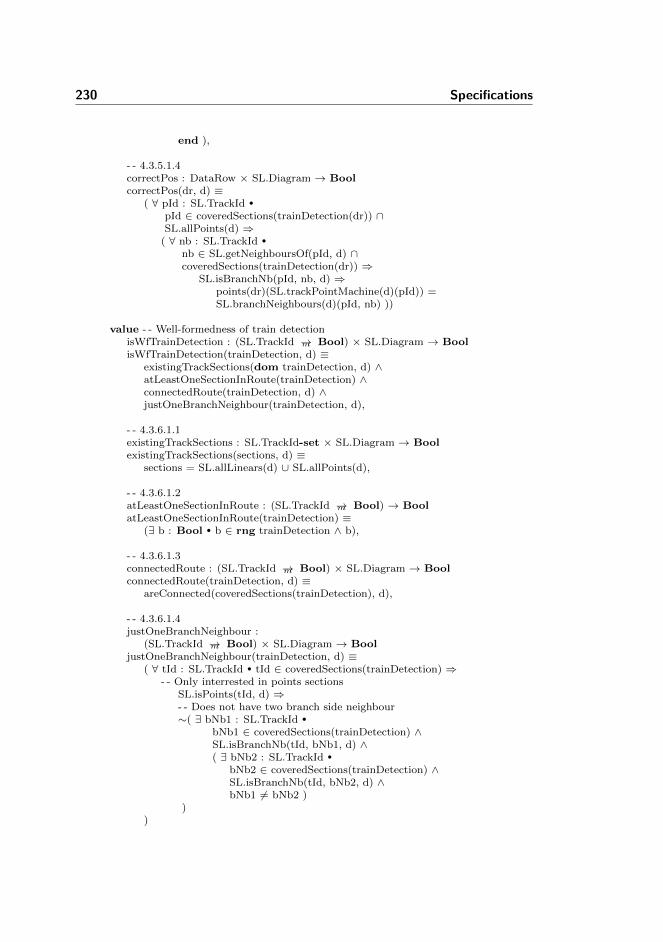
230 Specifications
end ),
- - 4.3.5.1.4correctPos : DataRow × SL.Diagram → BoolcorrectPos(dr, d) ≡
( ∀ pId : SL.TrackId •
pId ∈ coveredSections(trainDetection(dr)) ∩SL.allPoints(d) ⇒
( ∀ nb : SL.TrackId •
nb ∈ SL.getNeighboursOf(pId, d) ∩coveredSections(trainDetection(dr)) ⇒
SL.isBranchNb(pId, nb, d) ⇒points(dr)(SL.trackPointMachine(d)(pId)) =SL.branchNeighbours(d)(pId, nb) ))
value - - Well-formedness of train detectionisWfTrainDetection : (SL.TrackId →m Bool) × SL.Diagram → BoolisWfTrainDetection(trainDetection, d) ≡
existingTrackSections(dom trainDetection, d) ∧atLeastOneSectionInRoute(trainDetection) ∧connectedRoute(trainDetection, d) ∧justOneBranchNeighbour(trainDetection, d),
- - 4.3.6.1.1existingTrackSections : SL.TrackId-set × SL.Diagram → BoolexistingTrackSections(sections, d) ≡
sections = SL.allLinears(d) ∪ SL.allPoints(d),
- - 4.3.6.1.2atLeastOneSectionInRoute : (SL.TrackId →m Bool) → BoolatLeastOneSectionInRoute(trainDetection) ≡
(∃ b : Bool • b ∈ rng trainDetection ∧ b),
- - 4.3.6.1.3connectedRoute : (SL.TrackId →m Bool) × SL.Diagram → BoolconnectedRoute(trainDetection, d) ≡
areConnected(coveredSections(trainDetection), d),
- - 4.3.6.1.4justOneBranchNeighbour :
(SL.TrackId →m Bool) × SL.Diagram → BooljustOneBranchNeighbour(trainDetection, d) ≡
( ∀ tId : SL.TrackId • tId ∈ coveredSections(trainDetection) ⇒- - Only interrested in points sections
SL.isPoints(tId, d) ⇒- - Does not have two branch side neighbour∼( ∃ bNb1 : SL.TrackId •
bNb1 ∈ coveredSections(trainDetection) ∧SL.isBranchNb(tId, bNb1, d) ∧( ∃ bNb2 : SL.TrackId •
bNb2 ∈ coveredSections(trainDetection) ∧SL.isBranchNb(tId, bNb2, d) ∧bNb1 6= bNb2 )
))
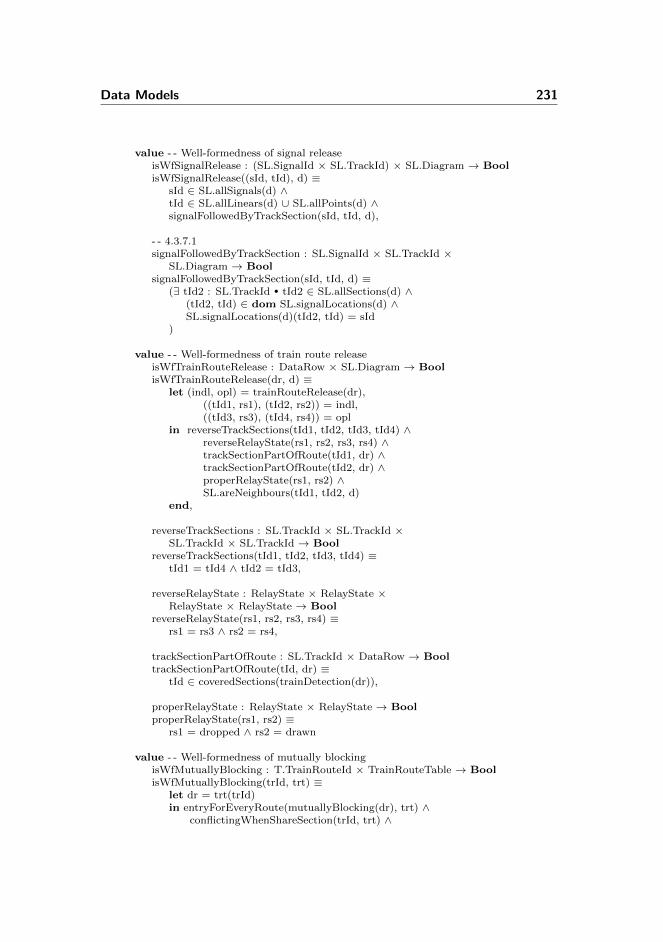
Data Models 231
value - - Well-formedness of signal releaseisWfSignalRelease : (SL.SignalId × SL.TrackId) × SL.Diagram → BoolisWfSignalRelease((sId, tId), d) ≡
sId ∈ SL.allSignals(d) ∧tId ∈ SL.allLinears(d) ∪ SL.allPoints(d) ∧signalFollowedByTrackSection(sId, tId, d),
- - 4.3.7.1signalFollowedByTrackSection : SL.SignalId × SL.TrackId ×
SL.Diagram → BoolsignalFollowedByTrackSection(sId, tId, d) ≡
(∃ tId2 : SL.TrackId • tId2 ∈ SL.allSections(d) ∧(tId2, tId) ∈ dom SL.signalLocations(d) ∧SL.signalLocations(d)(tId2, tId) = sId
)
value - - Well-formedness of train route releaseisWfTrainRouteRelease : DataRow × SL.Diagram → BoolisWfTrainRouteRelease(dr, d) ≡
let (indl, opl) = trainRouteRelease(dr),((tId1, rs1), (tId2, rs2)) = indl,((tId3, rs3), (tId4, rs4)) = opl
in reverseTrackSections(tId1, tId2, tId3, tId4) ∧reverseRelayState(rs1, rs2, rs3, rs4) ∧trackSectionPartOfRoute(tId1, dr) ∧trackSectionPartOfRoute(tId2, dr) ∧properRelayState(rs1, rs2) ∧SL.areNeighbours(tId1, tId2, d)
end,
reverseTrackSections : SL.TrackId × SL.TrackId ×SL.TrackId × SL.TrackId → Bool
reverseTrackSections(tId1, tId2, tId3, tId4) ≡tId1 = tId4 ∧ tId2 = tId3,
reverseRelayState : RelayState × RelayState ×RelayState × RelayState → Bool
reverseRelayState(rs1, rs2, rs3, rs4) ≡rs1 = rs3 ∧ rs2 = rs4,
trackSectionPartOfRoute : SL.TrackId × DataRow → BooltrackSectionPartOfRoute(tId, dr) ≡
tId ∈ coveredSections(trainDetection(dr)),
properRelayState : RelayState × RelayState → BoolproperRelayState(rs1, rs2) ≡
rs1 = dropped ∧ rs2 = drawn
value - - Well-formedness of mutually blockingisWfMutuallyBlocking : T.TrainRouteId × TrainRouteTable → BoolisWfMutuallyBlocking(trId, trt) ≡
let dr = trt(trId)in entryForEveryRoute(mutuallyBlocking(dr), trt) ∧
conflictingWhenShareSection(trId, trt) ∧
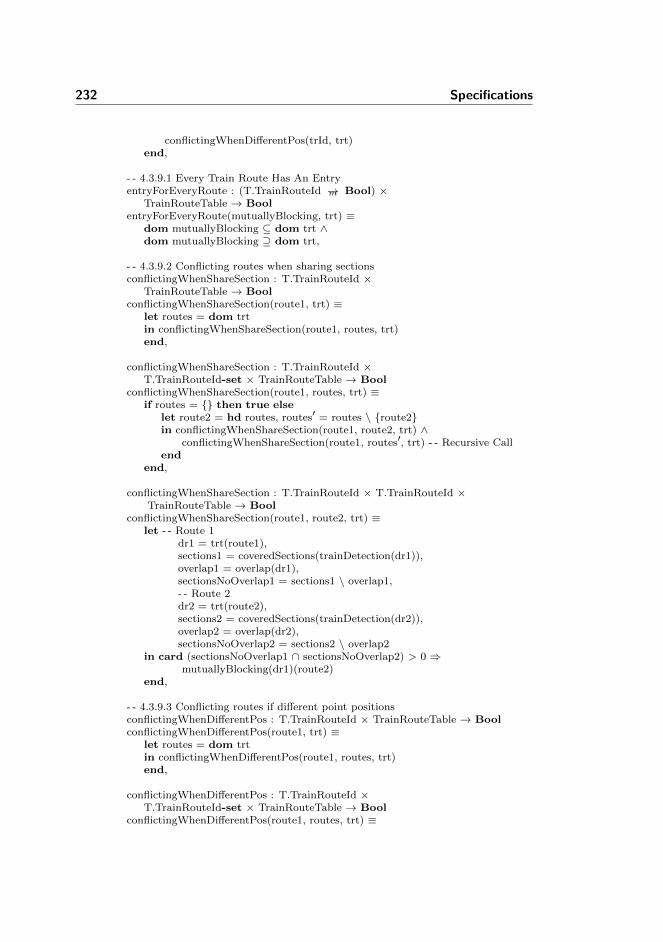
232 Specifications
conflictingWhenDifferentPos(trId, trt)end,
- - 4.3.9.1 Every Train Route Has An EntryentryForEveryRoute : (T.TrainRouteId →m Bool) ×
TrainRouteTable → BoolentryForEveryRoute(mutuallyBlocking, trt) ≡
dom mutuallyBlocking ⊆ dom trt ∧dom mutuallyBlocking ⊇ dom trt,
- - 4.3.9.2 Conflicting routes when sharing sectionsconflictingWhenShareSection : T.TrainRouteId ×
TrainRouteTable → BoolconflictingWhenShareSection(route1, trt) ≡
let routes = dom trtin conflictingWhenShareSection(route1, routes, trt)end,
conflictingWhenShareSection : T.TrainRouteId ×T.TrainRouteId-set × TrainRouteTable → Bool
conflictingWhenShareSection(route1, routes, trt) ≡if routes = {} then true else
let route2 = hd routes, routes′ = routes \ {route2}in conflictingWhenShareSection(route1, route2, trt) ∧
conflictingWhenShareSection(route1, routes′, trt) - - Recursive Callend
end,
conflictingWhenShareSection : T.TrainRouteId × T.TrainRouteId ×TrainRouteTable → Bool
conflictingWhenShareSection(route1, route2, trt) ≡let - - Route 1
dr1 = trt(route1),sections1 = coveredSections(trainDetection(dr1)),overlap1 = overlap(dr1),sectionsNoOverlap1 = sections1 \ overlap1,- - Route 2dr2 = trt(route2),sections2 = coveredSections(trainDetection(dr2)),overlap2 = overlap(dr2),sectionsNoOverlap2 = sections2 \ overlap2
in card (sectionsNoOverlap1 ∩ sectionsNoOverlap2) > 0 ⇒mutuallyBlocking(dr1)(route2)
end,
- - 4.3.9.3 Conflicting routes if different point positionsconflictingWhenDifferentPos : T.TrainRouteId × TrainRouteTable → BoolconflictingWhenDifferentPos(route1, trt) ≡
let routes = dom trtin conflictingWhenDifferentPos(route1, routes, trt)end,
conflictingWhenDifferentPos : T.TrainRouteId ×T.TrainRouteId-set × TrainRouteTable → Bool
conflictingWhenDifferentPos(route1, routes, trt) ≡

Data Models 233
if routes = {} then true elselet route2 = hd routes,
routes′ = routes \ {route2}in conflictingWhenDifferentPos(route1, route2, trt) ∧
conflictingWhenDifferentPos(route1, routes′, trt) - - Recursive Callend
end,
conflictingWhenDifferentPos : T.TrainRouteId × T.TrainRouteId ×TrainRouteTable → Bool
conflictingWhenDifferentPos(route1, route2, trt) ≡let - - Route 1
dr1 = trt(route1),points1 = points(dr1),- - Route 2dr2 = trt(route2),points2 = points(dr2)
in ( ∃ pmId : SL.PointMachineId •
pmId ∈ dom points1 ∧pmId ∈ dom points2 ∧points1(pmId) 6= T.arbitrary ∧points2(pmId) 6= T.arbitrary ∧points1(pmId) 6= points2(pmId)
) ⇒ mutuallyBlocking(dr1)(route2)end
end
E.1.5 Transition System
context: Tscheme TransitionSystem =
classtype
/∗ Variable in state of transition system ∗/Var ::
id : T.VarIdval : Val,
/∗ Value as boolean or natural number ∗/Val == mk BoolVal(b : Bool) | mk NatVal(n : Nat),
Assignment ::id : T.VarIdassign : T.AssignExp,
MultipleAssignment = Assignment-set,
TransitionRule ::name : Textguard : T.BooleanExp

234 Specifications
assignments : MultipleAssignment,
/∗ Assertion ∗/Assertion = Text × T.LTLformula,
TransitionSystem ::name : Textstate : Var-settransitionRules : TransitionRule-setassertions : Assertion-set
value /∗ Auxiliary functions ∗/isIdInState : T.VarId × Var-set → BoolisIdInState(id, state) ≡
( ∃ var : Var • var ∈ state ∧ id = id(var) ),
idsInBoolExp : T.BooleanExp → T.VarId-setidsInBoolExp(boolExp) ≡
case boolExp ofT.bool(b) → {},T.literal(l) → {l},T.and(a) → idsInBoolExp(a),T.or(o) → idsInBoolExp(o),T.neg(n) → idsInBoolExp(n),T.lessthan(l,r) →
idsInArithmeticExp(l) ∪ idsInArithmeticExp(r),T.greaterthan(l,r) →
idsInArithmeticExp(l) ∪ idsInArithmeticExp(r),T.geq(l,r) →
idsInArithmeticExp(l) ∪ idsInArithmeticExp(r),T.equals(l,r) →
idsInArithmeticExp(l) ∪ idsInArithmeticExp(r)end,
idsInBoolExp : T.BooleanExp-set → T.VarId-setidsInBoolExp(boolExps) ≡
let boolExp = hd boolExps, boolExps′ = boolExps \ {boolExp}in if boolExps = {} then {}
else idsInBoolExp(boolExp) ∪ idsInBoolExp(boolExps′)end
end,
idsInArithmeticExp : T.ArithmeticExp → T.VarId-setidsInArithmeticExp(aExp) ≡
case aExp ofT.add(a) → idsInArithmeticExp(a),T.sub(s) → idsInArithmeticExp(s),T.literal(l) → {l}
end,
idsInArithmeticExp : T.ArithmeticExp-set → T.VarId-setidsInArithmeticExp(aExps) ≡
let aExp = hd aExps, aExps′ = aExps \ {aExp}in if aExps = {} then {}
else idsInArithmeticExp(aExp) ∪

Data Models 235
idsInArithmeticExp(aExps′)end
end,
idsInLTL : T.LTLformula → T.VarId-setidsInLTL(ltl) ≡
case ltl ofT.b(boolExp) → idsInBoolExp(boolExp),T.ltrl(l) → {l},T.conj(ltls) → idsInLTL(ltls),T.disj(ltls) → idsInLTL(ltls),T.paren(ltl) → idsInLTL(ltl),T.neg(ltl) → idsInLTL(ltl),T.impl(ltl1, ltl2) → idsInLTL(ltl1) ∪ idsInLTL(ltl2),T.x(ltl) → idsInLTL(ltl),T.g(ltl) → idsInLTL(ltl),T.f(ltl) → idsInLTL(ltl),T.u(ltl1, ltl2) → idsInLTL(ltl1) ∪ idsInLTL(ltl2)
end,
idsInLTL : T.LTLformula-set → T.VarId-setidsInLTL(ltls) ≡
let ltl = hd ltls, ltls′ = ltls \ {ltl}in if ltls = {} then {}
else idsInLTL(ltl) ∪ idsInLTL(ltls′)end
end
value /∗ Well−formness ∗/isWfTransitionSystem : TransitionSystem → BoolisWfTransitionSystem(ts) ≡
isWfName(name(ts)) ∧isWfState(state(ts)) ∧isWfTransitionRules(ts) ∧isWfAssertions(ts)
value /∗ Well−formness of name ∗/isWfName : Text → BoolisWfName(name) ≡ name 6= ′′′′
value /∗ Well−formness of state ∗/isWfState : Var-set → BoolisWfState(vars) ≡ uniqueIds(vars) ∧ validIds(vars),
uniqueIds : Var-set → BooluniqueIds(vars) ≡
( ∀ var1 : Var • var1 ∈ vars ⇒∼( ∃ var2 : Var • var2 ∈ vars ∧
id(var1) = id(var2) ∧ var1 6= var2)),
validIds : Var-set → BoolvalidIds(vars) ≡
( ∀ var : Var • var ∈ vars ⇒id(var) 6= ′′′′ ∧
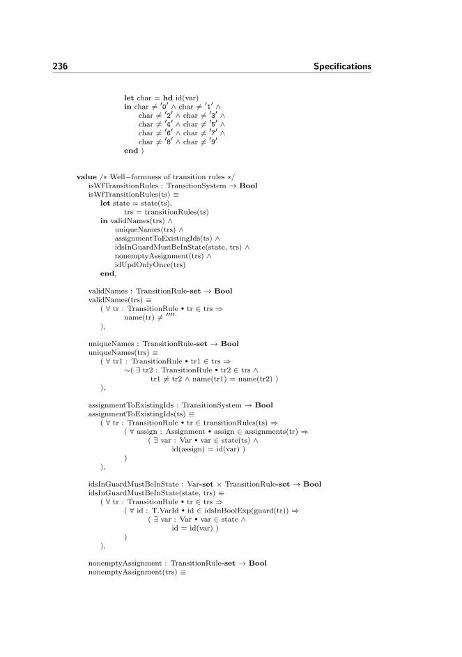
236 Specifications
let char = hd id(var)in char 6= ′0′ ∧ char 6= ′1′ ∧
char 6= ′2′ ∧ char 6= ′3′ ∧char 6= ′4′ ∧ char 6= ′5′ ∧char 6= ′6′ ∧ char 6= ′7′ ∧char 6= ′8′ ∧ char 6= ′9′
end )
value /∗ Well−formness of transition rules ∗/isWfTransitionRules : TransitionSystem → BoolisWfTransitionRules(ts) ≡
let state = state(ts),trs = transitionRules(ts)
in validNames(trs) ∧uniqueNames(trs) ∧assignmentToExistingIds(ts) ∧idsInGuardMustBeInState(state, trs) ∧nonemptyAssignment(trs) ∧idUpdOnlyOnce(trs)
end,
validNames : TransitionRule-set → BoolvalidNames(trs) ≡
( ∀ tr : TransitionRule • tr ∈ trs ⇒name(tr) 6= ′′′′
),
uniqueNames : TransitionRule-set → BooluniqueNames(trs) ≡
( ∀ tr1 : TransitionRule • tr1 ∈ trs ⇒∼( ∃ tr2 : TransitionRule • tr2 ∈ trs ∧
tr1 6= tr2 ∧ name(tr1) = name(tr2) )),
assignmentToExistingIds : TransitionSystem → BoolassignmentToExistingIds(ts) ≡
( ∀ tr : TransitionRule • tr ∈ transitionRules(ts) ⇒( ∀ assign : Assignment • assign ∈ assignments(tr) ⇒
( ∃ var : Var • var ∈ state(ts) ∧id(assign) = id(var) )
)),
idsInGuardMustBeInState : Var-set × TransitionRule-set → BoolidsInGuardMustBeInState(state, trs) ≡
( ∀ tr : TransitionRule • tr ∈ trs ⇒( ∀ id : T.VarId • id ∈ idsInBoolExp(guard(tr)) ⇒
( ∃ var : Var • var ∈ state ∧id = id(var) )
)),
nonemptyAssignment : TransitionRule-set → BoolnonemptyAssignment(trs) ≡

Data Models 237
( ∀ tr : TransitionRule • tr ∈ trs ⇒assignments(tr) 6= {}
),
idUpdOnlyOnce : TransitionRule-set → BoolidUpdOnlyOnce(trs) ≡
( ∀ tr : TransitionRule • tr ∈ trs ⇒let ma = assignments(tr)in ( ∀ assign : Assignment • assign ∈ ma ⇒
∼( ∃ assign2 : Assignment • assign2 ∈ ma ∧assign 6= assign2 ∧ id(assign) = id(assign2) )
)end
)
value /∗ Well−formness of assertions ∗/isWfAssertions : TransitionSystem → BoolisWfAssertions(ts) ≡
let state = state(ts),assertions = assertions(ts)
in nonemptyNames(assertions) ∧uniqueNames(assertions) ∧existingVars(state, assertions)
end,
nonemptyNames : Assertion-set → BoolnonemptyNames(assertions) ≡
( ∀ (name, ltl) : Assertion • (name, ltl) ∈ assertions ⇒name 6= ′′′′ ),
uniqueNames : Assertion-set → BooluniqueNames(assertions) ≡
( ∀ (name, ltl) : Assertion • (name, ltl) ∈ assertions ⇒∼( ∃ (name2, ltl2) : Assertion •
(name2, ltl2) ∈ assertions ∧(name, ltl) 6= (name2, ltl2) ∧name = name2 )
),
existingVars : Var-set × Assertion-set → BoolexistingVars(state, assertions) ≡
( ∀ (name, ltl) : Assertion • (name, ltl) ∈ assertions ⇒( ∀ id : T.VarId • id ∈ idsInLTL(ltl) ⇒
isIdInState(id, state) ))
end

238 Specifications
E.2 Generators
E.2.1 Objects
E.2.1.1 Generator
context: Generatorobject G : Generator
E.2.1.2 AssertionGenerator
context: AssertionGeneratorobject AG : AssertionGenerator
context: ConsistencyAssertionGeneratorobject CAG : ConsistencyAssertionGenerator
context: SafetyAssertionGeneratorobject SAG : SafetyAssertionGenerator
context: TrtAssertionGeneratorobject TAG : TrtAssertionGenerator
E.2.1.3 StateGenerator
context: StateGeneratorobject SG : StateGenerator
E.2.1.4 TransitionGenerator
context: TransitionGeneratorobject TG : TransitionGenerator
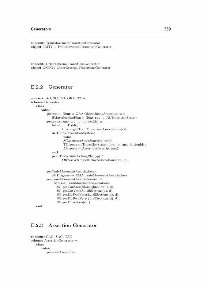
Generators 239
context: TrainMovementTransitionGeneratorobject TMTG : TrainMovementTransitionGenerator
context: OtherExternalTransitionsGeneratorobject OXTG : OtherExternalTransitionsGenerator
E.2.2 Generator
context: AG, SG, TG, ORA, TMAscheme Generator =
classvalue
generate : Text × ORA.ObjectRelayAssociations ×IP.InterlockingPlan × Text-set → TS.TransitionSystem
generate(name, ora, ip, buttonIds) ≡let sld = IP.sld(ip),
tma = genTrainMovementAssociations(sld)in TS.mk TransitionSystem(
name,SG.generateStateSpace(ip, tma),TG.generateTransitionSystem(ora, ip, tma, buttonIds),AG.generateAssertions(ora, ip, tma))
endpre IP.isWfInterlockingPlan(ip) ∧
ORA.isWfObjectRelayAssociations(ora, ip),
genTrainMovementAssociations :SL.Diagram → TMA.TrainMovementAssociations
genTrainMovementAssociations(d) ≡TMA.mk TrainMovementAssociations(
SG.genConVars(SL.neighbours(d), d),SG.genCntVars(SL.allSections(d), d),SG.genDirFwdVars(SL.allSections(d), d),SG.genDirBwdVars(SL.allSections(d), d),SG.genDirections(d) )
end
E.2.3 Assertion Generator
context: CAG, SAG, TAGscheme AssertionGenerator =
classvalue
generateAssertions :
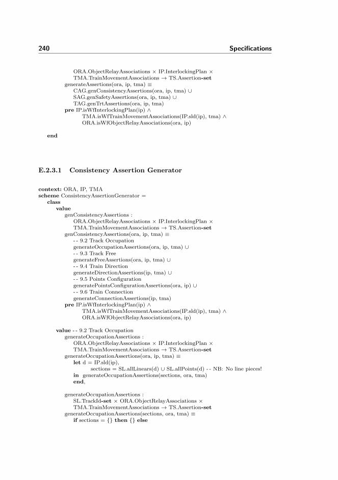
240 Specifications
ORA.ObjectRelayAssociations × IP.InterlockingPlan ×TMA.TrainMovementAssociations → TS.Assertion-set
generateAssertions(ora, ip, tma) ≡CAG.genConsistencyAssertions(ora, ip, tma) ∪SAG.genSafetyAssertions(ora, ip, tma) ∪TAG.genTrtAssertions(ora, ip, tma)
pre IP.isWfInterlockingPlan(ip) ∧TMA.isWfTrainMovementAssociations(IP.sld(ip), tma) ∧ORA.isWfObjectRelayAssociations(ora, ip)
end
E.2.3.1 Consistency Assertion Generator
context: ORA, IP, TMAscheme ConsistencyAssertionGenerator =
classvalue
genConsistencyAssertions :ORA.ObjectRelayAssociations × IP.InterlockingPlan ×TMA.TrainMovementAssociations → TS.Assertion-set
genConsistencyAssertions(ora, ip, tma) ≡- - 9.2 Track OccupationgenerateOccupationAssertions(ora, ip, tma) ∪- - 9.3 Track FreegenerateFreeAssertions(ora, ip, tma) ∪- - 9.4 Train DirectiongenerateDirectionAssertions(ip, tma) ∪- - 9.5 Points ConfigurationgeneratePointsConfigurationAssertions(ora, ip) ∪- - 9.6 Train ConnectiongenerateConnectionAssertions(ip, tma)
pre IP.isWfInterlockingPlan(ip) ∧TMA.isWfTrainMovementAssociations(IP.sld(ip), tma) ∧ORA.isWfObjectRelayAssociations(ora, ip)
value - - 9.2 Track OccupationgenerateOccupationAssertions :
ORA.ObjectRelayAssociations × IP.InterlockingPlan ×TMA.TrainMovementAssociations → TS.Assertion-set
generateOccupationAssertions(ora, ip, tma) ≡let d = IP.sld(ip),
sections = SL.allLinears(d) ∪ SL.allPoints(d) - - NB: No line pieces!in generateOccupationAssertions(sections, ora, tma)end,
generateOccupationAssertions :SL.TrackId-set × ORA.ObjectRelayAssociations ×TMA.TrainMovementAssociations → TS.Assertion-set
generateOccupationAssertions(sections, ora, tma) ≡if sections = {} then {} else

Generators 241
let s = hd sections,sections′ = sections \ {s}
in {generateOccupationAssertion1(s, ora, tma),generateOccupationAssertion2(s, ora, tma)} ∪
generateOccupationAssertions(sections′, ora, tma) - - Recursiveend
end,
- - cnt 01 ¿ 0 =¿ ∼01generateOccupationAssertion1 :
SL.TrackId × ORA.ObjectRelayAssociations ×TMA.TrainMovementAssociations → TS.Assertion
generateOccupationAssertion1(s, ora, tma) ≡(′′occ_′′ s,genOccuFormula1(s, ora, tma)),
genOccuFormula1 :SL.TrackId × ORA.ObjectRelayAssociations ×TMA.TrainMovementAssociations → T.LTLformula
genOccuFormula1(s, ora, tma) ≡T.g(T.impl(T.b(T.greaterthan(
T.literal(TMA.getCounterVar(s, tma)),T.literal(′′0′′))),T.neg(T.ltrl(ORA.trackRelayAssoc(ora)(s))))),
- - ∼01 =¿ cnt 01 ¿ 0generateOccupationAssertion2 :
SL.TrackId × ORA.ObjectRelayAssociations ×TMA.TrainMovementAssociations → TS.Assertion
generateOccupationAssertion2(s, ora, tma) ≡( ′′occ_′′ s ′′_′′,
genOccuFormula2(s, ora, tma) ),
genOccuFormula2 :SL.TrackId × ORA.ObjectRelayAssociations ×TMA.TrainMovementAssociations → T.LTLformula
genOccuFormula2(s, ora, tma) ≡T.g(
T.impl(T.neg(T.ltrl(ORA.trackRelayAssoc(ora)(s))),T.b(T.greaterthan(T.literal(TMA.getCounterVar(s, tma)),
T.literal(′′0′′)))))
value - - 9.3 Track FreegenerateFreeAssertions :
ORA.ObjectRelayAssociations × IP.InterlockingPlan ×TMA.TrainMovementAssociations → TS.Assertion-set
generateFreeAssertions(ora, ip, tma) ≡let d = IP.sld(ip),
sections = SL.allLinears(d) ∪ SL.allPoints(d) - - NB: No line pieces!in generateFreeAssertions(sections, ora, tma)end,
generateFreeAssertions :SL.TrackId-set × ORA.ObjectRelayAssociations ×TMA.TrainMovementAssociations → TS.Assertion-set

242 Specifications
generateFreeAssertions(sections, ora, tma) ≡if sections = {} then {} else
let s = hd sections,sections′ = sections \ {s}
in {generateFreeAssertion1(s, ora, tma),generateFreeAssertion2(s, ora, tma)} ∪
generateFreeAssertions(sections′, ora, tma) - - Recursiveend
end,
- - cnt 01 = 0 =¿ t01generateFreeAssertion1 :
SL.TrackId × ORA.ObjectRelayAssociations ×TMA.TrainMovementAssociations → TS.Assertion
generateFreeAssertion1(s, ora, tma) ≡(′′free_′′ s,genFreeFormula1(s, ora, tma)),
genFreeFormula1 :SL.TrackId × ORA.ObjectRelayAssociations ×TMA.TrainMovementAssociations → T.LTLformula
genFreeFormula1(s, ora, tma) ≡T.g(T.impl(T.b(T.equals(T.literal(TMA.getCounterVar(s, tma)),
T.literal(′′0′′))),T.ltrl(ORA.trackRelayAssoc(ora)(s)))),
- - t01 =¿ cnt 01 = 0generateFreeAssertion2 :
SL.TrackId × ORA.ObjectRelayAssociations ×TMA.TrainMovementAssociations → TS.Assertion
generateFreeAssertion2(s, ora, tma) ≡(′′free_′′ s ′′_′′,genFreeFormula2(s, ora, tma)),
genFreeFormula2 :SL.TrackId × ORA.ObjectRelayAssociations ×TMA.TrainMovementAssociations → T.LTLformula
genFreeFormula2(s, ora, tma) ≡T.g(T.impl(T.ltrl(ORA.trackRelayAssoc(ora)(s)),
T.b(T.equals(T.literal(TMA.getCounterVar(s, tma)),T.literal(′′0′′)))))
value - - 9.4 Train DirectiongenerateDirectionAssertions : IP.InterlockingPlan ×
TMA.TrainMovementAssociations → TS.Assertion-setgenerateDirectionAssertions(ip, tma) ≡
let d = IP.sld(ip),sections = SL.allLinears(d) ∪ SL.allPoints(d) - - NB: No line pieces!
in generateDirectionAssertions(sections, tma)end,
generateDirectionAssertions : SL.TrackId-set ×TMA.TrainMovementAssociations → TS.Assertion-set
generateDirectionAssertions(sections, tma) ≡if sections = {} then {} else

Generators 243
let s = hd sections,sections′ = sections \ {s}
in {generateDirectionAssertion(s, tma)} ∪generateDirectionAssertions(sections′, tma) - - Recursive
endend,
generateDirectionAssertion : SL.TrackId ×TMA.TrainMovementAssociations → TS.Assertion
generateDirectionAssertion(tId, tma) ≡(′′direction_′′ tId,genDirFormula(tId, tma)
),
genDirFormula : SL.TrackId ×TMA.TrainMovementAssociations → T.LTLformula
genDirFormula(tId, tma) ≡let trackFwd = TMA.getDirVar(tId, T.fwd, tma),
trackBwd = TMA.getDirVar(tId, T.bwd, tma),trackCnt = TMA.getCounterVar(tId, tma)
in T.g(T.impl(T.disj({T.ltrl(trackFwd), T.ltrl(trackBwd)}),T.b(T.greaterthan(T.literal(trackCnt), T.literal(′′0′′)))))
end
value - - 9.5 Points ConfigurationgeneratePointsConfigurationAssertions :
ORA.ObjectRelayAssociations ×IP.InterlockingPlan → TS.Assertion-set
generatePointsConfigurationAssertions(ora, ip) ≡let d = IP.sld(ip),
allPoints = SL.allPoints(d)in generatePointsConfigurationAssertions(allPoints, d, ora)end,
generatePointsConfigurationAssertions :SL.TrackId-set × SL.Diagram ×ORA.ObjectRelayAssociations → TS.Assertion-set
generatePointsConfigurationAssertions(sections, d, ora) ≡if sections = {} then {} else
let s = hd sections,sections′ = sections \ {s}
in {generatePointsConfigurationAssertion(s, d, ora)} ∪generatePointsConfigurationAssertions(sections′, d, ora) - - Recursive
endend,
generatePointsConfigurationAssertion :SL.TrackId × SL.Diagram ×ORA.ObjectRelayAssociations → TS.Assertion
generatePointsConfigurationAssertion(s, d, ora) ≡(′′points_configuration_′′ s,genPointsConfigFormula(s, d, ora)),
genPointsConfigFormula : SL.TrackId × SL.Diagram ×
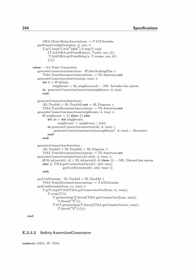
244 Specifications
ORA.ObjectRelayAssociations → T.LTLformulagenPointsConfigFormula(s, d, ora) ≡
T.g(T.impl(T.ltrl(′′idle′′),T.neg(T.conj({T.ltrl(ORA.getPointRelay(s, T.plus, ora, d)),T.ltrl(ORA.getPointRelay(s, T.minus, ora, d))}))))
value - - 9.6 Train ConnectiongenerateConnectionAssertions : IP.InterlockingPlan ×
TMA.TrainMovementAssociations → TS.Assertion-setgenerateConnectionAssertions(ip, tma) ≡
let d = IP.sld(ip),neighbours = SL.neighbours(d) - - NB: Includes line pieces
in generateConnectionAssertions(neighbours, d, tma)end,
generateConnectionAssertions :(SL.TrackId × SL.TrackId)-set × SL.Diagram ×TMA.TrainMovementAssociations → TS.Assertion-set
generateConnectionAssertions(neighbours, d, tma) ≡if neighbours = {} then {} else
let nb = hd neighbours,neighbours′ = neighbours \ {nb}
in generateConnectionAssertion(nb, d, tma) ∪generateConnectionAssertions(neighbours′, d, tma) - - Recursive
endend,
generateConnectionAssertion :(SL.TrackId × SL.TrackId) × SL.Diagram ×TMA.TrainMovementAssociations → TS.Assertion-set
generateConnectionAssertion((nb1,nb2), d, tma) ≡if SL.isLine(nb1, d) ∨ SL.isLine(nb2, d) then {} - - NB: Discard line pieceselse {( TMA.getConnectionVar(nb1, nb2, tma),
genConFormula(nb1, nb2, tma) )}end,
genConFormula : SL.TrackId × SL.TrackId ×TMA.TrainMovementAssociations → T.LTLformula
genConFormula(from, to, tma) ≡T.g(T.impl(T.ltrl(TMA.getConnectionVar(from, to, tma)),
T.conj({T.b(T.greaterthan(T.literal(TMA.getCounterVar(from, tma)),
T.literal(′′0′′))),T.b(T.greaterthan(T.literal(TMA.getCounterVar(to, tma)),
T.literal(′′0′′)))})))
end
E.2.3.2 SafetyAssertionGenerator
context: ORA, IP, TMA

Generators 245
scheme SafetyAssertionGenerator =class
valuegenSafetyAssertions :
ORA.ObjectRelayAssociations × IP.InterlockingPlan ×TMA.TrainMovementAssociations → TS.Assertion-set
genSafetyAssertions(ora, ip, tma) ≡- - 10.2 No CollisiongenNoCollisionAssertions(ip, tma) ∪- - 10.3 No DerailinggenNoDerailingAssertions(ora, ip, tma)
pre IP.isWfInterlockingPlan(ip) ∧TMA.isWfTrainMovementAssociations(IP.sld(ip), tma) ∧ORA.isWfObjectRelayAssociations(ora, ip)
value - - 10.2 No CollisiongenNoCollisionAssertions : IP.InterlockingPlan ×
TMA.TrainMovementAssociations → TS.Assertion-setgenNoCollisionAssertions(ip, tma) ≡
let d = IP.sld(ip),sections = SL.allLinears(d) ∪ SL.allPoints(d) - - NB: No line pieces!
in generateNoCollisionAssertions(sections, tma)end,
generateNoCollisionAssertions : SL.TrackId-set ×TMA.TrainMovementAssociations → TS.Assertion-set
generateNoCollisionAssertions(sections, tma) ≡if sections = {} then {} else
let s = hd sections,sections′ = sections \ {s}
in {generateNoCollisionAssertion(s, tma)} ∪generateNoCollisionAssertions(sections′, tma) - - Recursive call
endend,
generateNoCollisionAssertion : SL.TrackId ×TMA.TrainMovementAssociations → TS.Assertion
generateNoCollisionAssertion(s, tma) ≡(′′no_collision_′′ s,genNoColFormula(s, tma) ),
genNoColFormula : SL.TrackId ×TMA.TrainMovementAssociations → T.LTLformula
genNoColFormula(s, tma) ≡T.g(T.b(T.lessthan(T.literal(TMA.getCounterVar(s, tma)),
T.literal(′′2′′))))
value - - 10.3 No DerailinggenNoDerailingAssertions :
ORA.ObjectRelayAssociations × IP.InterlockingPlan ×TMA.TrainMovementAssociations → TS.Assertion-set
genNoDerailingAssertions(ora, ip, tma) ≡let d = IP.sld(ip),
sections = SL.allPoints(d),branchNbs = dom SL.branchNeighbours(d)
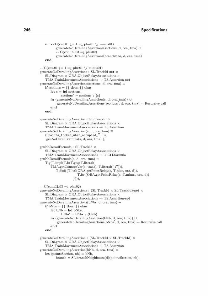
246 Specifications
in - - G(cnt 01 ¿= 1 =¿ plus01 \/ minus01)generateNoDerailingAssertions(sections, d, ora, tma) ∪- - G(con 02 03 =¿ plus02)generateNoDerailingAssertions(branchNbs, d, ora, tma)
end,
- - G(cnt 01 ¿= 1 =¿ plus01 \/ minus01)generateNoDerailingAssertions : SL.TrackId-set ×
SL.Diagram × ORA.ObjectRelayAssociations ×TMA.TrainMovementAssociations → TS.Assertion-set
generateNoDerailingAssertions(sections, d, ora, tma) ≡if sections = {} then {} else
let s = hd sections,sections′ = sections \ {s}
in {generateNoDerailingAssertion(s, d, ora, tma)} ∪generateNoDerailingAssertions(sections′, d, ora, tma) - - Recursive call
endend,
generateNoDerailingAssertion : SL.TrackId ×SL.Diagram × ORA.ObjectRelayAssociations ×TMA.TrainMovementAssociations → TS.Assertion
generateNoDerailingAssertion(s, d, ora, tma) ≡(′′points_locked_when_occupied_′′ s,genNoDerailFormula(s, d, ora, tma) ),
genNoDerailFormula : SL.TrackId ×SL.Diagram × ORA.ObjectRelayAssociations ×TMA.TrainMovementAssociations → T.LTLformula
genNoDerailFormula(s, d, ora, tma) ≡T.g(T.impl(T.b(T.geq(T.literal(
TMA.getCounterVar(s, tma)), T.literal(′′1′′))),T.disj({T.ltrl(ORA.getPointRelay(s, T.plus, ora, d)),
T.ltrl(ORA.getPointRelay(s, T.minus, ora, d))}))),
- - G(con 02 03 =¿ plus02)generateNoDerailingAssertions : (SL.TrackId × SL.TrackId)-set ×
SL.Diagram × ORA.ObjectRelayAssociations ×TMA.TrainMovementAssociations → TS.Assertion-set
generateNoDerailingAssertions(bNbs, d, ora, tma) ≡if bNbs = {} then {} else
let bNb = hd bNbs,bNbs′ = bNbs \ {bNb}
in {generateNoDerailingAssertion(bNb, d, ora, tma)} ∪generateNoDerailingAssertions(bNbs′, d, ora, tma) - - Recursive call
endend,
generateNoDerailingAssertion : (SL.TrackId × SL.TrackId) ×SL.Diagram × ORA.ObjectRelayAssociations ×TMA.TrainMovementAssociations → TS.Assertion
generateNoDerailingAssertion(bNb, d, ora, tma) ≡let (pointsSection, nb) = bNb,
branch = SL.branchNeighbours(d)(pointsSection, nb),

Generators 247
conVar = TMA.getConnectionVar(pointsSection, nb, tma),branchVar = ORA.getPointRelay(pointsSection, branch, ora, d)
in (′′no_derailing_′′ pointsSection ′′_′′ nb,T.g(T.impl(T.ltrl(conVar), T.ltrl(branchVar))))
end
end
E.2.3.3 TrtAssertionGenerator
context: ORA, IP, TMAscheme TrtAssertionGenerator =
classvalue
genTrtAssertions :ORA.ObjectRelayAssociations × IP.InterlockingPlan ×TMA.TrainMovementAssociations → TS.Assertion-set
genTrtAssertions(ora, ip, tma) ≡- - 10.4 Points PositiongenPointsPositionAssertions(ora, IP.trt(ip)) ∪- - 10.5 SignalgenSignalAssertions(ora, ip) ∪- - 10.6 Signal ReleasegenSignalReleaseAssertions(ora, ip) ∪- - 10.7 Conflicting RoutesgenConflictingRoutesAssertions(ora, ip) ∪- - 10.8 Train Route ReleasegenTrainRouteReleaseAssertions(ora, ip)
pre IP.isWfInterlockingPlan(ip) ∧TMA.isWfTrainMovementAssociations(IP.sld(ip), tma) ∧ORA.isWfObjectRelayAssociations(ora, ip)
value - - 10.4 Points PositiongenPointsPositionAssertions : ORA.ObjectRelayAssociations ×
TRT.TrainRouteTable → TS.Assertion-setgenPointsPositionAssertions(ora, trt) ≡
let lockingRelays = rng ORA.routeRelayAssoc(ora)in generatePointPositionAssertions(lockingRelays, ora, trt)end,
generatePointPositionAssertions :T.VarId-set × ORA.ObjectRelayAssociations ×TRT.TrainRouteTable → TS.Assertion-set
generatePointPositionAssertions(lockingRelays, ora, trt) ≡if lockingRelays = {} then {} else
let relayId = hd lockingRelays,lockingRelays′ = lockingRelays \ {relayId}
in {genPointPosAssert(relayId, ora, trt)} ∪generatePointPositionAssertions(lockingRelays′, ora, trt)
endend,
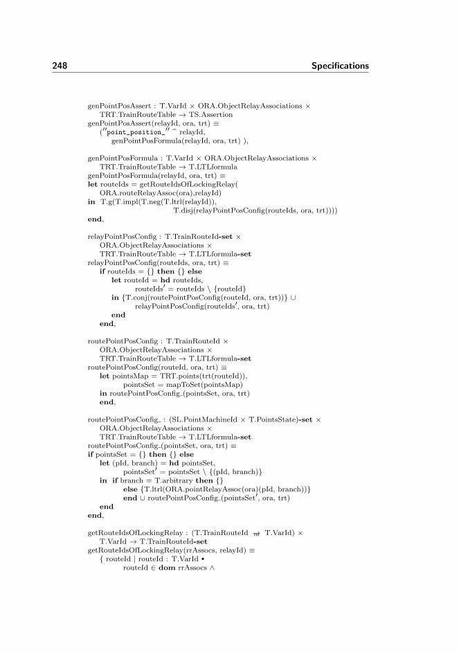
248 Specifications
genPointPosAssert : T.VarId × ORA.ObjectRelayAssociations ×TRT.TrainRouteTable → TS.Assertion
genPointPosAssert(relayId, ora, trt) ≡(′′point_position_′′ relayId,
genPointPosFormula(relayId, ora, trt) ),
genPointPosFormula : T.VarId × ORA.ObjectRelayAssociations ×TRT.TrainRouteTable → T.LTLformula
genPointPosFormula(relayId, ora, trt) ≡let routeIds = getRouteIdsOfLockingRelay(
ORA.routeRelayAssoc(ora),relayId)in T.g(T.impl(T.neg(T.ltrl(relayId)),
T.disj(relayPointPosConfig(routeIds, ora, trt))))end,
relayPointPosConfig : T.TrainRouteId-set ×ORA.ObjectRelayAssociations ×TRT.TrainRouteTable → T.LTLformula-set
relayPointPosConfig(routeIds, ora, trt) ≡if routeIds = {} then {} else
let routeId = hd routeIds,routeIds′ = routeIds \ {routeId}
in {T.conj(routePointPosConfig(routeId, ora, trt))} ∪relayPointPosConfig(routeIds′, ora, trt)
endend,
routePointPosConfig : T.TrainRouteId ×ORA.ObjectRelayAssociations ×TRT.TrainRouteTable → T.LTLformula-set
routePointPosConfig(routeId, ora, trt) ≡let pointsMap = TRT.points(trt(routeId)),
pointsSet = mapToSet(pointsMap)in routePointPosConfig (pointsSet, ora, trt)end,
routePointPosConfig : (SL.PointMachineId × T.PointsState)-set ×ORA.ObjectRelayAssociations ×TRT.TrainRouteTable → T.LTLformula-set
routePointPosConfig (pointsSet, ora, trt) ≡if pointsSet = {} then {} else
let (pId, branch) = hd pointsSet,pointsSet′ = pointsSet \ {(pId, branch)}
in if branch = T.arbitrary then {}else {T.ltrl(ORA.pointRelayAssoc(ora)(pId, branch))}end ∪ routePointPosConfig (pointsSet′, ora, trt)
endend,
getRouteIdsOfLockingRelay : (T.TrainRouteId →m T.VarId) ×T.VarId → T.TrainRouteId-set
getRouteIdsOfLockingRelay(rrAssocs, relayId) ≡{ routeId | routeId : T.VarId •
routeId ∈ dom rrAssocs ∧
Generators 249
rrAssocs(routeId) = relayId}
value - - 10.5 SignalgenSignalAssertions : ORA.ObjectRelayAssociations ×
IP.InterlockingPlan → TS.Assertion-setgenSignalAssertions(ora, ip) ≡
let d = IP.sld(ip),trt = IP.trt(ip)
in generateSignalAspectAssertions(d, ora, trt) ∪generateSignalLockingAssertions(d, ora, trt)
end,
generateSignalAspectAssertions :SL.Diagram × ORA.ObjectRelayAssociations ×TRT.TrainRouteTable → TS.Assertion-set
generateSignalAspectAssertions(d, ora, trt) ≡generateSignalAspectAssertions(SL.allSignals(d), ora, trt),
generateSignalAspectAssertions :SL.SignalId-set × ORA.ObjectRelayAssociations ×TRT.TrainRouteTable → TS.Assertion-set
generateSignalAspectAssertions(allSignals, ora, trt) ≡if allSignals = {} then {} else
let signalId = hd allSignals,allSignals′ = allSignals \ {signalId}
in {generateSignalAspectAssertion(signalId, ora)} ∪- - Recursive callgenerateSignalAspectAssertions(allSignals′, ora, trt)
endend,
generateSignalAspectAssertion : SL.SignalId ×ORA.ObjectRelayAssociations → TS.Assertion
generateSignalAspectAssertion(signalId, a) ≡(′′signal_′′ signalId,
genSignalAspectFormula(signalId, a)),
genSignalAspectFormula : SL.SignalId ×ORA.ObjectRelayAssociations → T.LTLformula
genSignalAspectFormula(signalId, a) ≡let gr = ORA.signalRelayAssoc(a)(signalId, ORA.gr),
re = ORA.signalRelayAssoc(a)(signalId, ORA.re)in T.g(T.impl(T.ltrl(′′idle′′),
T.neg(T.conj({T.ltrl(gr), T.ltrl(re)}))))end,
- - Signal lockinggenerateSignalLockingAssertions :
SL.Diagram × ORA.ObjectRelayAssociations ×TRT.TrainRouteTable → TS.Assertion-set
generateSignalLockingAssertions(d, ora, trt) ≡let allSignals = SL.allSignals(d)in generateSignalLockingAssertions(allSignals, ora, trt)end,

250 Specifications
generateSignalLockingAssertions :SL.SignalId-set × ORA.ObjectRelayAssociations ×TRT.TrainRouteTable → TS.Assertion-set
generateSignalLockingAssertions(signals, ora, trt) ≡if signals = {} then {} else
let s = hd signals,signals′ = signals \ {s}
in {generateSignalLockingAssertion(s, ora, trt)} ∪- - Recursive CallgenerateSignalLockingAssertions(signals′, ora, trt)
endend,
generateSignalLockingAssertion :SL.SignalId × ORA.ObjectRelayAssociations ×TRT.TrainRouteTable → TS.Assertion
generateSignalLockingAssertion(signalId, ora, trt) ≡(′′signal_exp_′′ signalId,
genSigFormula(signalId, ora, trt)),
genSigFormula :SL.SignalId × ORA.ObjectRelayAssociations ×TRT.TrainRouteTable → T.LTLformula
genSigFormula(signalId, ora, trt) ≡let coveredRoutes = getRoutesCoveredBySignal(signalId, trt),
grVarId = ORA.signalRelayAssoc(ora)(signalId, ORA.gr)in T.g(T.impl(T.conj({T.ltrl(′′idle′′), T.ltrl(grVarId)}),
T.disj(getReservations(coveredRoutes, signalId, ora, trt))))
end,
getReservations : T.TrainRouteId-set ×SL.SignalId × ORA.ObjectRelayAssociations ×TRT.TrainRouteTable → T.LTLformula-set
getReservations(trainRoutes, signalId, a, trt) ≡if trainRoutes = {} then {} else
let routeId = hd trainRoutes,trainRoutes′ = trainRoutes \ {routeId},tracksFree = getReqFreeTracks(trt, routeId),redSignals = getSignalAspectRoutes1(routeId, TRT.re, trt),nonConflictRoutes = getNonConflictingRoutes(
TRT.mutuallyBlocking(trt(routeId)), routeId)in if getIfGreenSignalIsMoreThanOnce1(
signalId, dom trt, trt, 0) > 1then{T.paren(T.conj({T.neg(T.ltrl(
ORA.routeRelayAssoc(a)(routeId)))}∪routePointPosConfig(routeId, a, trt) ∪getTrackRelays(tracksFree, a) ∪getSignalRelays(redSignals, ORA.re, a) ∪{T.disj(getRouteRelayPointPosConfigSignal(nonConflictRoutes, routeId, a, trt))}))}else{T.paren(T.conj({T.neg(T.ltrl(
Generators 251
ORA.routeRelayAssoc(a)(routeId)))} ∪routePointPosConfig(routeId, a, trt) ∪getTrackRelays(tracksFree, a) ∪getSignalRelays(redSignals, ORA.re, a)))}end∪
getReservations(trainRoutes′,signalId, a, trt)end
end,
getRouteRelayPointPosConfigSignal : T.TrainRouteId-set ×T.TrainRouteId × ORA.ObjectRelayAssociations ×TRT.TrainRouteTable → T.LTLformula-set
getRouteRelayPointPosConfigSignal(routeIds, currentRouteId, a, trt) ≡if routeIds = {} then {} else
let routeId = hd routeIds, routeIds′ = routeIds \ {routeId},signalsGr =
getSignalAspectRoutes(routeId, TRT.gr, trt),signalsRe =
getSignalAspectRoutes(routeId, TRT.re, trt),signalRED =
getSignalAspectRoutes(currentRouteId, TRT.re, trt)in {T.paren(T.disj({
T.conj(getSignalRelays(signalRED, ORA.re, a)),T.paren(T.conj({T.neg(T.ltrl(
ORA.routeRelayAssoc(a)(routeId)))} ∪routePointPosConfig(routeId, a, trt) ∪getSignalRelays(signalsGr, ORA.gr, a) ∪getSignalRelays(signalsRe, ORA.re, a)))
}))}∪ getRouteRelayPointPosConfigSignal(
routeIds′, currentRouteId, a, trt)end
end,
getTrackRelays : SL.TrackId-set ×ORA.ObjectRelayAssociations → T.LTLformula-set
getTrackRelays(tIds, a) ≡if tIds = {} then {} else
let tId = hd tIds, tIds′ = tIds \ {tId}in {T.ltrl(ORA.getTrackRelay(tId, a))} ∪
getTrackRelays(tIds′, a)end
end,
getSignalRelays : SL.SignalId-set × ORA.Lamp ×ORA.ObjectRelayAssociations → T.LTLformula-set
getSignalRelays(signals,asp, a) ≡if signals = {} then {} else
let signalId = hd signals,signals′ = signals \ {signalId}
in {T.ltrl(ORA.signalRelayAssoc(a)(signalId, asp))} ∪getSignalRelays(signals′, asp, a)
endend,

252 Specifications
getSignalAspectRoutes :T.TrainRouteId × TRT.Aspect ×TRT.TrainRouteTable → SL.SignalId-set
getSignalAspectRoutes(routeId, aspect, trt) ≡{signalId | signalId : SL.SignalId •
signalId ∈ dom TRT.signals(trt(routeId)) ∧TRT.signals(trt(routeId))(signalId) = aspect},
getSignalAspectRoutes1 :T.TrainRouteId × TRT.Aspect ×TRT.TrainRouteTable → SL.SignalId-set
getSignalAspectRoutes1(routeId, aspect, trt) ≡{signalId | signalId : SL.SignalId •
signalId ∈ dom TRT.signals(trt(routeId)) ∧TRT.signals(trt(routeId))(signalId) = aspect ∧∼isSignalGreenInNonConflictingRoute(
routeId, dom trt, signalId, trt)},
isSignalGreenInNonConflictingRoute :T.TrainRouteId × T.TrainRouteId-set ×SL.SignalId × TRT.TrainRouteTable → Bool
isSignalGreenInNonConflictingRoute(routeId, allRoutes, signalId, trt) ≡if allRoutes = {} then false else
let curRouteId = hd allRoutes,allRoutes′ = allRoutes \ {curRouteId},mutualBlock = TRT.mutuallyBlocking(trt(routeId)),nonConflict = getNonConflictingRoutes(mutualBlock, routeId)
in containsTrueInSet(nonConflict, signalId, trt)end
end,
containsTrueInSet :T.TrainRouteId-set × SL.SignalId ×TRT.TrainRouteTable → Bool
containsTrueInSet(allNonConflictRoutes, signalId, trt) ≡let set = isSignalGreenInNonConflictingRoutes(
allNonConflictRoutes, signalId, trt),set′ = set \ {hd set}
in hd setend,
isSignalGreenInNonConflictingRoutes : T.TrainRouteId-set ×SL.SignalId × TRT.TrainRouteTable → Bool-set
isSignalGreenInNonConflictingRoutes(allNonConflictRoutes, signalId, trt) ≡if allNonConflictRoutes = {} then {false} else
let routeId = hd allNonConflictRoutes,allNonConflictRoutes′ = allNonConflictRoutes \ {routeId}
in if TRT.signals(trt(routeId))(signalId) = TRT.gr then {true}else {false}end ∪ isSignalGreenInNonConflictingRoutes(
allNonConflictRoutes′, signalId, trt)end
end,

Generators 253
getRoutesCoveredBySignal : SL.SignalId ×TRT.TrainRouteTable → T.TrainRouteId-set
getRoutesCoveredBySignal(signalId, trt) ≡{routeId | routeId : T.TrainRouteId •
routeId ∈ dom trt ∧signalId ∈ dom TRT.signals(trt(routeId)) ∧TRT.signals(trt(routeId))(signalId) = TRT.gr},
getReqFreeTracks : TRT.TrainRouteTable ×T.TrainRouteId → T.VarId-set
getReqFreeTracks(trt, routeId) ≡{trackId | trackId : SL.TrackId •
trackId ∈ dom TRT.trainDetection(trt(routeId)) ∧TRT.trainDetection(trt(routeId))(trackId) },
getIfGreenSignalIsMoreThanOnce1 : SL.SignalId ×T.TrainRouteId-set × TRT.TrainRouteTable × Nat → Nat
getIfGreenSignalIsMoreThanOnce1(signalId, allRoutes, trt, counter) ≡if allRoutes = {} then counter else
let routeId = hd allRoutes,allRoutes′ = allRoutes \ {routeId}
in if TRT.signals(trt(routeId))(signalId) = TRT.grthen getIfGreenSignalIsMoreThanOnce1(
signalId, allRoutes′, trt, counter + 1)else getIfGreenSignalIsMoreThanOnce1(
signalId, allRoutes′, trt, counter)end
endend
value - - 10.6 Signal ReleasegenSignalReleaseAssertions : ORA.ObjectRelayAssociations ×
IP.InterlockingPlan → TS.Assertion-setgenSignalReleaseAssertions(ora, ip) ≡
let trt = IP.trt(ip),routeIds = dom trt
in genSignalReleaseAssertions(dom IP.trt(ip), ora, trt)end,
genSignalReleaseAssertions :T.TrainRouteId-set × ORA.ObjectRelayAssociations ×TRT.TrainRouteTable → TS.Assertion-set
genSignalReleaseAssertions(routeIds, ora, trt) ≡if routeIds = {} then {} else
let routeId = hd routeIds,routeIds′ = routeIds \ {routeId}
in {generateSignalReleaseAssertion(routeId, ora, trt)} ∪- - Recursive CallgenSignalReleaseAssertions(routeIds′, ora, trt)
endend,
generateSignalReleaseAssertion :T.TrainRouteId × ORA.ObjectRelayAssociations ×TRT.TrainRouteTable → TS.Assertion

254 Specifications
generateSignalReleaseAssertion(routeId, ora, trt) ≡(′′signal_release_′′ routeId,
genSignalReleaseFormula(routeId, ora, trt)),
genSignalReleaseFormula :T.TrainRouteId × ORA.ObjectRelayAssociations ×TRT.TrainRouteTable → T.LTLformula
genSignalReleaseFormula(routeId, ora, trt) ≡let (sId, tId) = TRT.signalRelease(trt(routeId)),
trackRelayId = ORA.trackRelayAssoc(ora)(tId),signalAspect = ORA.signalRelayAssoc(ora)(sId, ORA.re)
inT.g(T.impl(T.conj({T.ltrl(′′idle′′),
T.neg(T.ltrl(trackRelayId))}),T.ltrl(signalAspect)))
end
value - - 10.7 Conflicting RoutesgenConflictingRoutesAssertions : ORA.ObjectRelayAssociations ×
IP.InterlockingPlan → TS.Assertion-setgenConflictingRoutesAssertions(ora, ip) ≡
let trt = IP.trt(ip),routeIds = dom trt
in genConflictingRoutesAssertions(routeIds, ora, trt)end,
genConflictingRoutesAssertions :T.TrainRouteId-set × ORA.ObjectRelayAssociations ×TRT.TrainRouteTable → TS.Assertion-set
genConflictingRoutesAssertions(routeIds, ora, trt) ≡if routeIds = {} then {} else
let routeId = hd routeIds,routeIds′ = routeIds \ {routeId}
in {generateConflictingRouteAssertion(routeId, ora, trt)} ∪- - Recursive CallgenConflictingRoutesAssertions(routeIds′, ora, trt)
endend,
generateConflictingRouteAssertion :T.TrainRouteId × ORA.ObjectRelayAssociations ×TRT.TrainRouteTable → TS.Assertion
generateConflictingRouteAssertion(routeId, ora, trt) ≡(′′conflicting_route_′′ routeId,
genConflictRouteFormula(routeId, ora, trt)),
genConflictRouteFormula :T.TrainRouteId × ORA.ObjectRelayAssociations ×TRT.TrainRouteTable → T.LTLformula
genConflictRouteFormula(routeId, ora, trt) ≡T.g(T.impl(T.conj({T.neg(T.ltrl(ORA.routeRelayAssoc(ora)(routeId)))} ∪routePointPosConfig(routeId, ora, trt)),T.conj(getRouteRelayAndPointPosConfig(
Generators 255
getConflictingRoutes(TRT.mutuallyBlocking(trt(routeId)),routeId), routeId, ora, trt)))),
getConflictingRoutes : (T.TrainRouteId →m Bool) ×T.TrainRouteId → T.TrainRouteId-set
getConflictingRoutes(mutuallyBlocking, routeId) ≡{routeId | routeId : T.TrainRouteId •
routeId ∈ dom mutuallyBlocking ∧mutuallyBlocking(routeId)},
getRouteRelayAndPointPosConfig : T.TrainRouteId-set ×T.TrainRouteId × ORA.ObjectRelayAssociations ×TRT.TrainRouteTable → T.LTLformula-set
getRouteRelayAndPointPosConfig(routeIds, routeId, ora, trt) ≡if routeIds = {} then {} else
let currentRouteId = hd routeIds,routeIds′ = routeIds \ {currentRouteId}
in if currentRouteId = routeId then {} else{T.neg(T.conj({T.neg(T.ltrl(
ORA.routeRelayAssoc(ora)(currentRouteId)))}∪ routePointPosConfig(currentRouteId, ora, trt)))}
end ∪ getRouteRelayAndPointPosConfig(routeIds′, routeId, ora, trt)
endend
value - - 10.8 Train Route ReleasegenTrainRouteReleaseAssertions : ORA.ObjectRelayAssociations ×
IP.InterlockingPlan → TS.Assertion-setgenTrainRouteReleaseAssertions(ora, ip) ≡
let trt = IP.trt(ip),routeIds = dom trt
in genTrainRouteReleaseAssertions(routeIds, ora, trt)end,
genTrainRouteReleaseAssertions :T.TrainRouteId-set × ORA.ObjectRelayAssociations ×TRT.TrainRouteTable→ TS.Assertion-set
genTrainRouteReleaseAssertions(routeIds, ora, trt) ≡if routeIds = {} then {} else
let routeId = hd routeIds,routeIds′ = routeIds \ {routeId}
in {generateRouteReleaseAssertion(routeId, ora, trt)} ∪- - Recursive CallgenTrainRouteReleaseAssertions(routeIds′, ora, trt)
endend,
generateRouteReleaseAssertion :T.TrainRouteId × ORA.ObjectRelayAssociations ×TRT.TrainRouteTable → TS.Assertion
generateRouteReleaseAssertion(routeId, ora, trt) ≡(′′train_route_release_′′ routeId,
genRouteReleaseFormula(routeId, ora, trt)),
256 Specifications
trackRelayState : SL.TrackId × TRT.RelayState ×ORA.ObjectRelayAssociations → T.LTLformula
trackRelayState(tId, rs, ora) ≡let rId = ORA.trackRelayAssoc(ora)(tId)in if rs = TRT.dropped then T.neg(T.ltrl(rId))
else T.ltrl(rId) endend,
genPointReqPos : (SL.PointMachineId × T.PointsState)-set ×ORA.ObjectRelayAssociations → T.LTLformula-set
genPointReqPos(points, ora) ≡if points = {} then {}else let (pId, ps) = hd points,
points′ = points \ {(pId, ps)}in if ps = T.arbitrary then {}
else {T.ltrl(ORA.pointRelayAssoc(ora)(pId, ps))}end ∪ genPointReqPos(points′, ora)
endend,
genRouteReleaseFormula :T.TrainRouteId × ORA.ObjectRelayAssociations ×TRT.TrainRouteTable → T.LTLformula
genRouteReleaseFormula(routeId, ora, trt) ≡let routeRelay = ORA.routeRelayAssoc(ora)(routeId),
route not locked = T.ltrl(routeRelay),route locked = T.neg(route not locked),
requiredPointPositions = T.conj(genPointReqPos(mapToSet(
TRT.points(trt(routeId))), ora) ),
(initiation, dissolve) =TRT.trainRouteRelease(trt(routeId)),
((init tId1, init rs1),(init tId2, init rs2)) = initiation,((diss tId1, diss rs1),(diss tId2, diss rs2)) = dissolve,
- - Initiation triggerinit tr1 = trackRelayState(init tId1, init rs1, ora),init tr2 = trackRelayState(init tId2, init rs2, ora),init = T.conj( {init tr1, init tr2} ),
- - Dissolve triggerdiss tr1 = trackRelayState(diss tId1, diss rs1, ora),diss tr2 = trackRelayState(diss tId2, diss rs2, ora),diss = T.conj( {diss tr1, diss tr2} )
in T.g( T.impl( T.conj({route not locked,T.x(T.conj({
route locked,requiredPointPositions,T.f(route not locked) }) ) }),
T.x(T.u(route locked, T.conj({route locked,

Generators 257
init,T.x(T.u(route locked,T.conj({
route locked, diss })) ) })))
))end
value - - AUX –- - helper function for point position and train route releasemapToSet : (SL.PointMachineId →m T.PointsState) →
(SL.PointMachineId × T.PointsState)-setmapToSet(map) ≡ mapToSet(dom map, map),
mapToSet : SL.PointMachineId-set ×(SL.PointMachineId →m T.PointsState) →(SL.PointMachineId × T.PointsState)-set
mapToSet(keys, map) ≡if keys = {} then {} else
let key = hd keys, keys′ = keys \ {key}in {(key, map(key))} ∪ mapToSet(keys′, map)end
end,
getNonConflictingRoutes : (T.TrainRouteId →m Bool) ×T.TrainRouteId → T.TrainRouteId-set
getNonConflictingRoutes(mutuallyBlocking, routeId) ≡{routeId | routeId : T.TrainRouteId •
routeId ∈ dom mutuallyBlocking ∧∼mutuallyBlocking(routeId)}
end
E.2.4 State Generator
context: TS, SL, TMA, IPscheme StateGenerator =
classvalue /∗ Generator functions for model catalog ∗/
genConVars :(SL.TrackId × SL.TrackId)-set × SL.Diagram →(SL.TrackId × SL.TrackId) →m T.VarId
genConVars(nbs, d) ≡if nbs = {} then [ ] else
let (nb1,nb2) = hd nbs, nbs′ = nbs \ {(nb1,nb2)}in if SL.isLine(nb1, d) ∨ SL.isLine(nb2, d)
then genConVars(nbs′, d)else genConVar(nb1, nb2) ∪ genConVars(nbs′, d)end
endend,
genConVar : SL.TrackId × SL.TrackId →

258 Specifications
(SL.TrackId × SL.TrackId) →m T.VarIdgenConVar(id1, id2) ≡ [ (id1,id2) 7→ ′′con_′′ id1 ′′_′′ id2 ],
genCntVars : SL.TrackId-set × SL.Diagram → SL.TrackId →m T.VarIdgenCntVars(ids, d) ≡
if ids = {} then [ ] elselet id = hd ids, ids′ = ids \ {id}in if SL.isLine(id, d) then [ ]
else genCntVar(id)end ∪ genCntVars(ids′, d)
endend,
genCntVar : SL.TrackId → SL.TrackId →m T.VarIdgenCntVar(id) ≡ [ id 7→ ′′cnt_′′ id ],
genDirFwdVars : SL.TrackId-set ×SL.Diagram → SL.TrackId →m T.VarId
genDirFwdVars(ids, d) ≡if ids = {} then [ ] else
let id = hd ids, ids′ = ids \ {id}in if SL.isLine(id, d) then [ ]
else genFwdVar(id)end ∪ genDirFwdVars(ids′, d)
endend,
genFwdVar : SL.TrackId → SL.TrackId →m T.VarIdgenFwdVar(id) ≡ [ id 7→ ′′fwd_′′ id ],
genDirBwdVars : SL.TrackId-set ×SL.Diagram → SL.TrackId →m T.VarId
genDirBwdVars(ids, d) ≡if ids = {} then [ ] else
let id = hd ids, ids′ = ids \ {id}in if SL.isLine(id, d) then [ ]
else genBwdVar(id)end ∪ genDirBwdVars(ids′, d)
endend,
genBwdVar : SL.TrackId → SL.TrackId →m T.VarIdgenBwdVar(id) ≡ [ id 7→ ′′bwd_′′ id ],
genDirections : SL.Diagram →(SL.TrackId × SL.TrackId) →m T.Direction
genDirections(d) ≡let nbs = SL.getNeighboursOf(SL.line(d), d), nb = hd nbsin dirTraverse({nb}, {SL.line(d)}, d) †
dirSourceAndSinks(nb, nbs, d)end
value /∗ Helper functions for generating the directions ∗/dirSourceAndSinks : SL.TrackId ×
SL.TrackId-set × SL.Diagram →
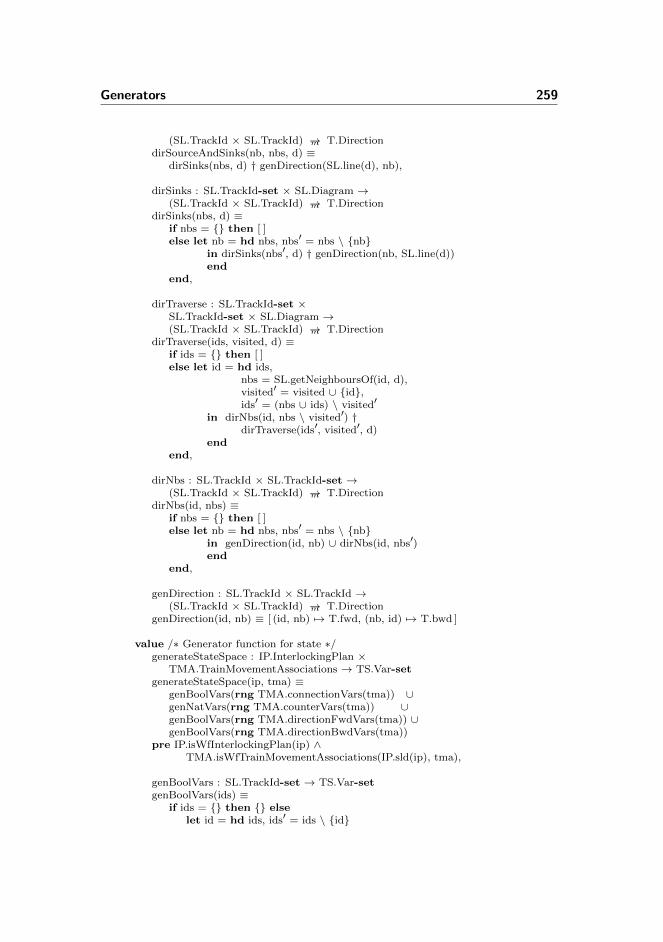
Generators 259
(SL.TrackId × SL.TrackId) →m T.DirectiondirSourceAndSinks(nb, nbs, d) ≡
dirSinks(nbs, d) † genDirection(SL.line(d), nb),
dirSinks : SL.TrackId-set × SL.Diagram →(SL.TrackId × SL.TrackId) →m T.Direction
dirSinks(nbs, d) ≡if nbs = {} then [ ]else let nb = hd nbs, nbs′ = nbs \ {nb}
in dirSinks(nbs′, d) † genDirection(nb, SL.line(d))end
end,
dirTraverse : SL.TrackId-set ×SL.TrackId-set × SL.Diagram →(SL.TrackId × SL.TrackId) →m T.Direction
dirTraverse(ids, visited, d) ≡if ids = {} then [ ]else let id = hd ids,
nbs = SL.getNeighboursOf(id, d),visited′ = visited ∪ {id},ids′ = (nbs ∪ ids) \ visited′
in dirNbs(id, nbs \ visited′) †dirTraverse(ids′, visited′, d)
endend,
dirNbs : SL.TrackId × SL.TrackId-set →(SL.TrackId × SL.TrackId) →m T.Direction
dirNbs(id, nbs) ≡if nbs = {} then [ ]else let nb = hd nbs, nbs′ = nbs \ {nb}
in genDirection(id, nb) ∪ dirNbs(id, nbs′)end
end,
genDirection : SL.TrackId × SL.TrackId →(SL.TrackId × SL.TrackId) →m T.Direction
genDirection(id, nb) ≡ [ (id, nb) 7→ T.fwd, (nb, id) 7→ T.bwd ]
value /∗ Generator function for state ∗/generateStateSpace : IP.InterlockingPlan ×
TMA.TrainMovementAssociations → TS.Var-setgenerateStateSpace(ip, tma) ≡
genBoolVars(rng TMA.connectionVars(tma)) ∪genNatVars(rng TMA.counterVars(tma)) ∪genBoolVars(rng TMA.directionFwdVars(tma)) ∪genBoolVars(rng TMA.directionBwdVars(tma))
pre IP.isWfInterlockingPlan(ip) ∧TMA.isWfTrainMovementAssociations(IP.sld(ip), tma),
genBoolVars : SL.TrackId-set → TS.Var-setgenBoolVars(ids) ≡
if ids = {} then {} elselet id = hd ids, ids′ = ids \ {id}

260 Specifications
in genBoolVars(ids′) ∪ {TS.mk Var(id, TS.mk BoolVal(false))}end
end,
genNatVars : SL.TrackId-set → TS.Var-setgenNatVars(ids) ≡
if ids = {} then {} elselet id = hd ids, ids′ = ids \ {id}in genNatVars(ids′) ∪ {TS.mk Var(id, TS.mk NatVal(0))}end
end
end
E.2.5 Transition Generator
context: OXTG, TMTGscheme TransitionGenerator =
classvalue
generateTransitionSystem : ORA.ObjectRelayAssociations ×IP.InterlockingPlan × TMA.TrainMovementAssociations ×Text-set → TS.TransitionRule-set
generateTransitionSystem(ora, ip, tma, buttons) ≡let d = IP.sld(ip),
allSections = SL.allSections(d)in TMTG.genTrainMovementTransitions(ora, d, tma) ∪
OXTG.genOtherExternalTransitions(buttons, ora, ip)end
pre IP.isWfInterlockingPlan(ip) ∧TMA.isWfTrainMovementAssociations(IP.sld(ip), tma) ∧ORA.isWfObjectRelayAssociations(ora, ip)
end
E.2.5.1 Train Movement Transition Generator
context: ORA, TMAscheme TrainMovementTransitionGenerator =
classvalue
genTrainMovementTransitions :ORA.ObjectRelayAssociations × SL.Diagram ×TMA.TrainMovementAssociations → TS.TransitionRule-set
genTrainMovementTransitions(ora, d, tma) ≡- - 6.3.1 Enter StationgenEnterStationRules(ora, d, tma) ∪

Generators 261
- - 6.3.2 Enter Track SectiongenEnterSectionRules(ora, d, tma) ∪- - 6.3.3 Leave StationgenLeaveStationRules(ora, d, tma) ∪- - 6.3.4 Leave Track SectiongenLeaveSectionRules(ora, d, tma) ∪- - 6.3.5 Change DirectiongenChangeDirectionRules(ora, d, tma)
value - - 6.3.1 Enter StationgenEnterStationRules :
ORA.ObjectRelayAssociations × SL.Diagram ×TMA.TrainMovementAssociations → TS.TransitionRule-set
genEnterStationRules(ora, d, tma) ≡let line = SL.line(d),
nbs = SL.getNeighboursOf(line, d)in genEnterStationRules(nbs, ora, d, tma)end,
genEnterStationRules : SL.TrackId-set ×ORA.ObjectRelayAssociations × SL.Diagram ×TMA.TrainMovementAssociations → TS.TransitionRule-set
genEnterStationRules(nbs, ora, d, tma) ≡if nbs = {} then {} else
let nb = hd nbs,nbs′ = nbs \ {nb}
in {genEnterStationRule(nb, ora, d, tma)} ∪genEnterStationRules(nbs′, ora, d, tma) - - Recursive Call
endend,
genEnterStationRule :SL.TrackId × ORA.ObjectRelayAssociations ×SL.Diagram × TMA.TrainMovementAssociations → TS.TransitionRule
genEnterStationRule(nb, ora, d, tma) ≡let line = SL.line(d),
dir = TMA.getDirection(line, nb, tma),name = genEnterRuleName(line, nb),guard = T.and( { idle } ∪
proceedAspect(line, nb, ora, d) ),update = { systemBusy,
addTrain(nb, tma),dropTrackRelay(nb, ora),setDirection(nb, dir, tma) }
in TS.mk TransitionRule(name, guard, update)end
value - - 6.3.2 Enter Track SectiongenEnterSectionRules : ORA.ObjectRelayAssociations × SL.Diagram ×
TMA.TrainMovementAssociations → TS.TransitionRule-setgenEnterSectionRules(ora, d, tma) ≡
let nbs = { (tId1, tId2) | (tId1, tId2) : (SL.TrackId × SL.TrackId) •
(tId1, tId2) ∈ SL.neighbours(d) ∧∼SL.isLine(tId1, d) ∧ ∼SL.isLine(tId2, d) }
in genEnterSectionRules(nbs, ora, d, tma)

262 Specifications
end,
genEnterSectionRules : (SL.TrackId × SL.TrackId)-set ×ORA.ObjectRelayAssociations × SL.Diagram ×TMA.TrainMovementAssociations → TS.TransitionRule-set
genEnterSectionRules(nbs, ora, d, tma) ≡if nbs = {} then {} else
let (tId1, tId2) = hd nbs,nbs′ = nbs \ {(tId1, tId2)}
in - - From tId1 to tId2genEnterSectionRule(tId1, tId2, ora, d, tma) ∪- - From tId2 to tId1genEnterSectionRule(tId2, tId1, ora, d, tma) ∪- - Recursive CallgenEnterSectionRules(nbs′, ora, d, tma)
endend,
genEnterSectionRule : SL.TrackId × SL.TrackId ×ORA.ObjectRelayAssociations × SL.Diagram ×TMA.TrainMovementAssociations → TS.TransitionRule-set
genEnterSectionRule(from, to, ora, d, tma) ≡- - 6.3.2.1 Facing Move - Stem Sideif SL.isPoints(to, d) ∧ SL.isStemNb(to, from, d)then {genEnterLinearSectionRule(from, to, ora, d, tma)}
- - 6.3.2.1 Facing Move - Branch Sideelsif SL.isPoints(from, d) ∧ SL.isBranchNb(from, to, d)then {genEnterFacingBranchSideRule(from, to, ora, d, tma)}
- - 6.3.2.1 Trailing Move - Stem Sideelsif SL.isPoints(from, d) ∧ SL.isStemNb(from, to, d)then {genEnterLinearSectionRule(from, to, ora, d, tma)}
- - 6.3.2.1 Trailing Move - Branch Sideelsif SL.isPoints(to, d) ∧ SL.isBranchNb(to, from, d)then { - - Correct pos
genEnterFacingBranchSideRule(from, to, ora, d, tma),- - Incorrect posgenEnterTrailingBranchSideRule(from, to, ora, d, tma)}
else - - 6.3.2 Linear{genEnterLinearSectionRule(from, to, ora, d, tma)}
end,
genEnterLinearSectionRule : SL.TrackId × SL.TrackId ×ORA.ObjectRelayAssociations × SL.Diagram ×TMA.TrainMovementAssociations → TS.TransitionRule
genEnterLinearSectionRule(from, to, ora, d, tma) ≡let dir = TMA.getDirection(from, to, tma),
name = ′′enter_′′ to ′′_from_′′ from,guard = T.and({ idle,
trackOccupied(from, tma),direction(from, to, tma),

Generators 263
notConnected(from, to, tma) } ∪- - If move passes signalif SL.hasSignal(from, to, d)then proceedAspect(from, to, ora, d) else {} end),
update = {systemBusy,addTrain(to, tma),dropTrackRelay(to, ora),connect(to, from, tma),setDirection(to, dir, tma) }
in TS.mk TransitionRule(name, guard, update)end,
genEnterFacingBranchSideRule : SL.TrackId × SL.TrackId ×ORA.ObjectRelayAssociations × SL.Diagram ×TMA.TrainMovementAssociations → TS.TransitionRule
genEnterFacingBranchSideRule(from, to, ora, d, tma) ≡let dir = TMA.getDirection(from, to, tma),
name = ′′enter_′′ to ′′_from_′′ from,guard = T.and({ idle,
trackOccupied(from, tma),direction(from, to, tma),notConnected(from, to, tma),branchGuard(to, from, ora, d) } ∪
- - If move passes signalif SL.hasSignal(from, to, d)then proceedAspect(from, to, ora, d) else {} end),
update = {systemBusy,addTrain(to, tma),dropTrackRelay(to, ora),connect(to, from, tma),setDirection(to, dir, tma) }
in TS.mk TransitionRule(name, guard, update)end,
genEnterTrailingBranchSideRule : SL.TrackId × SL.TrackId ×ORA.ObjectRelayAssociations × SL.Diagram ×TMA.TrainMovementAssociations → TS.TransitionRule
genEnterTrailingBranchSideRule(from, to, ora, d, tma) ≡let name = ′′enter_′′ to ′′_from_′′ from ′′_derail′′,
guard = T.and({ idle,
trackOccupied(from, tma),direction(from, to, tma),notConnected(from, to, tma),T.neg(branchGuard(from, to, ora, d)) } ∪
- - If move passes signalif SL.hasSignal(from, to, d)then proceedAspect(from, to, ora, d) else {} end),
update = {systemBusy,addTrain(to, tma),dropTrackRelay(to, ora),
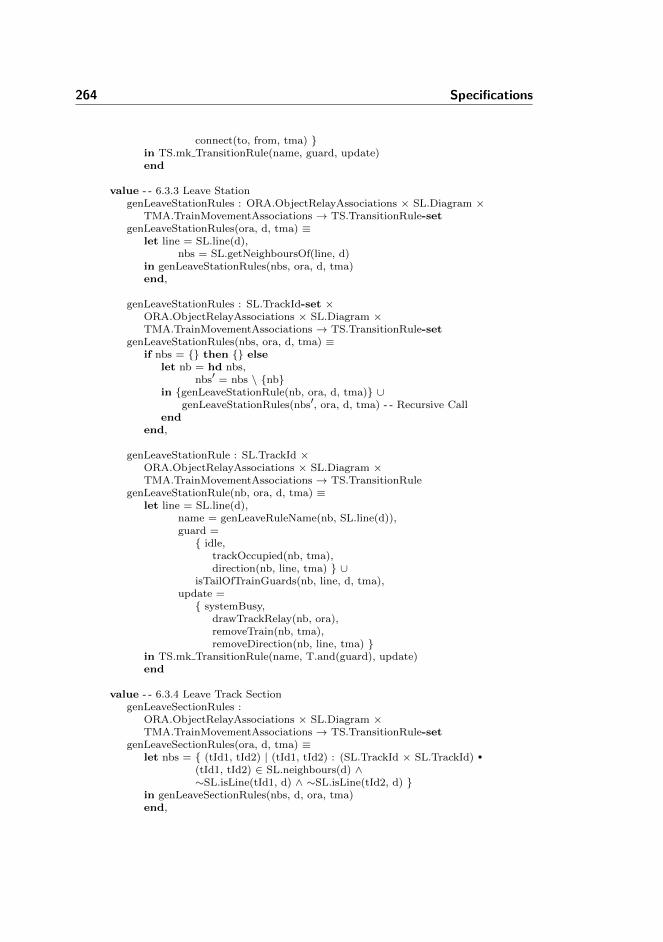
264 Specifications
connect(to, from, tma) }in TS.mk TransitionRule(name, guard, update)end
value - - 6.3.3 Leave StationgenLeaveStationRules : ORA.ObjectRelayAssociations × SL.Diagram ×
TMA.TrainMovementAssociations → TS.TransitionRule-setgenLeaveStationRules(ora, d, tma) ≡
let line = SL.line(d),nbs = SL.getNeighboursOf(line, d)
in genLeaveStationRules(nbs, ora, d, tma)end,
genLeaveStationRules : SL.TrackId-set ×ORA.ObjectRelayAssociations × SL.Diagram ×TMA.TrainMovementAssociations → TS.TransitionRule-set
genLeaveStationRules(nbs, ora, d, tma) ≡if nbs = {} then {} else
let nb = hd nbs,nbs′ = nbs \ {nb}
in {genLeaveStationRule(nb, ora, d, tma)} ∪genLeaveStationRules(nbs′, ora, d, tma) - - Recursive Call
endend,
genLeaveStationRule : SL.TrackId ×ORA.ObjectRelayAssociations × SL.Diagram ×TMA.TrainMovementAssociations → TS.TransitionRule
genLeaveStationRule(nb, ora, d, tma) ≡let line = SL.line(d),
name = genLeaveRuleName(nb, SL.line(d)),guard ={ idle,
trackOccupied(nb, tma),direction(nb, line, tma) } ∪
isTailOfTrainGuards(nb, line, d, tma),update ={ systemBusy,
drawTrackRelay(nb, ora),removeTrain(nb, tma),removeDirection(nb, line, tma) }
in TS.mk TransitionRule(name, T.and(guard), update)end
value - - 6.3.4 Leave Track SectiongenLeaveSectionRules :
ORA.ObjectRelayAssociations × SL.Diagram ×TMA.TrainMovementAssociations → TS.TransitionRule-set
genLeaveSectionRules(ora, d, tma) ≡let nbs = { (tId1, tId2) | (tId1, tId2) : (SL.TrackId × SL.TrackId) •
(tId1, tId2) ∈ SL.neighbours(d) ∧∼SL.isLine(tId1, d) ∧ ∼SL.isLine(tId2, d) }
in genLeaveSectionRules(nbs, d, ora, tma)end,
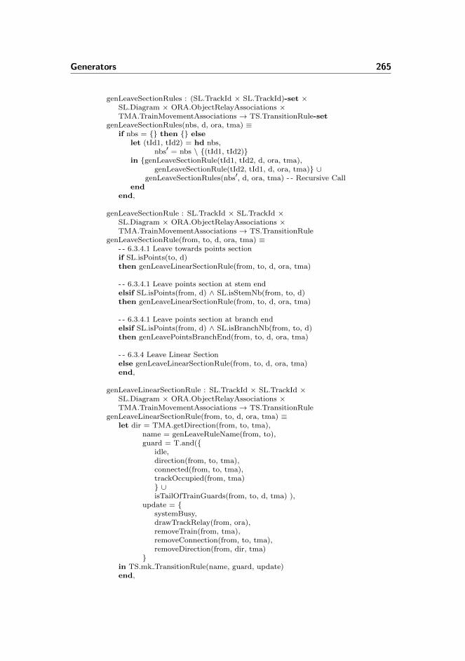
Generators 265
genLeaveSectionRules : (SL.TrackId × SL.TrackId)-set ×SL.Diagram × ORA.ObjectRelayAssociations ×TMA.TrainMovementAssociations → TS.TransitionRule-set
genLeaveSectionRules(nbs, d, ora, tma) ≡if nbs = {} then {} else
let (tId1, tId2) = hd nbs,nbs′ = nbs \ {(tId1, tId2)}
in {genLeaveSectionRule(tId1, tId2, d, ora, tma),genLeaveSectionRule(tId2, tId1, d, ora, tma)} ∪
genLeaveSectionRules(nbs′, d, ora, tma) - - Recursive Callend
end,
genLeaveSectionRule : SL.TrackId × SL.TrackId ×SL.Diagram × ORA.ObjectRelayAssociations ×TMA.TrainMovementAssociations → TS.TransitionRule
genLeaveSectionRule(from, to, d, ora, tma) ≡- - 6.3.4.1 Leave towards points sectionif SL.isPoints(to, d)then genLeaveLinearSectionRule(from, to, d, ora, tma)
- - 6.3.4.1 Leave points section at stem endelsif SL.isPoints(from, d) ∧ SL.isStemNb(from, to, d)then genLeaveLinearSectionRule(from, to, d, ora, tma)
- - 6.3.4.1 Leave points section at branch endelsif SL.isPoints(from, d) ∧ SL.isBranchNb(from, to, d)then genLeavePointsBranchEnd(from, to, d, ora, tma)
- - 6.3.4 Leave Linear Sectionelse genLeaveLinearSectionRule(from, to, d, ora, tma)end,
genLeaveLinearSectionRule : SL.TrackId × SL.TrackId ×SL.Diagram × ORA.ObjectRelayAssociations ×TMA.TrainMovementAssociations → TS.TransitionRule
genLeaveLinearSectionRule(from, to, d, ora, tma) ≡let dir = TMA.getDirection(from, to, tma),
name = genLeaveRuleName(from, to),guard = T.and({
idle,direction(from, to, tma),connected(from, to, tma),trackOccupied(from, tma)} ∪isTailOfTrainGuards(from, to, d, tma) ),
update = {systemBusy,drawTrackRelay(from, ora),removeTrain(from, tma),removeConnection(from, to, tma),removeDirection(from, dir, tma)
}in TS.mk TransitionRule(name, guard, update)end,

266 Specifications
genLeavePointsBranchEnd : SL.TrackId × SL.TrackId ×SL.Diagram × ORA.ObjectRelayAssociations ×TMA.TrainMovementAssociations → TS.TransitionRule
genLeavePointsBranchEnd(from, to, d, ora, tma) ≡let dir = TMA.getDirection(from, to, tma),
name = genLeaveRuleName(from, to),guard = T.and({
idle,direction(from, to, tma),connected(from, to, tma),trackOccupied(from, tma),branchGuard(from, to, ora, d)} ∪isTailOfTrainGuards(from, to, d, tma) ),
update = {systemBusy,drawTrackRelay(from, ora),removeTrain(from, tma),removeConnection(from, to, tma),removeDirection(from, dir, tma)
}in TS.mk TransitionRule(name, guard, update)end
value - - 6.3.5 Change DirectiongenChangeDirectionRules :
ORA.ObjectRelayAssociations × SL.Diagram ×TMA.TrainMovementAssociations → TS.TransitionRule-set
genChangeDirectionRules(ora, d, tma) ≡let allSignalLocations = dom SL.signalLocations(d)in genChangeDirectionRules(allSignalLocations, ora, d, tma)end,
genChangeDirectionRules : (SL.TrackId × SL.TrackId)-set ×ORA.ObjectRelayAssociations × SL.Diagram ×TMA.TrainMovementAssociations → TS.TransitionRule-set
genChangeDirectionRules(signalLocations, ora, d, tma) ≡if signalLocations = {} then {} else
let (tId1, tId2) = hd signalLocations,signalLocations′ = signalLocations \ {(tId1, tId2)}
in - - Recursive CallgenChangeDirectionRules(signalLocations′, ora, d, tma) ∪if tId1 = SL.line(d) then {}else {genChangeDirectionRule(tId1, tId2, ora, d, tma)}end
endend,
genChangeDirectionRule : SL.TrackId × SL.TrackId ×ORA.ObjectRelayAssociations × SL.Diagram ×TMA.TrainMovementAssociations → TS.TransitionRule
genChangeDirectionRule(from, to, a, d, tma) ≡let curDir = TMA.directions(tma)(from, to),
oppDir = T.oppositeDirection(curDir),

Generators 267
name = ′′change_direction_at_′′ from ′′_towards_′′ to,guard = { idle,
trackOccupied(from, tma),direction(from, to, tma) } ∪
proceedAspect(from, to, a, d) ∪isTailOfTrainGuards(from, to, d, tma),
update = { setDirection(from, oppDir, tma),removeDirection(from, curDir, tma)}
in TS.mk TransitionRule(name, T.and(guard), update)end
value - - AUXisHeadOfTrainGuard : SL.TrackId × SL.TrackId ×
TMA.TrainMovementAssociations → T.BooleanExpisHeadOfTrainGuard(s, inFront, tma) ≡
T.neg(T.literal(TMA.getConnectionVar(s, inFront, tma))),
isTailOfTrainGuards : SL.TrackId × SL.TrackId ×SL.Diagram × TMA.TrainMovementAssociations → T.BooleanExp-set
isTailOfTrainGuards(from, to, d, tma) ≡let nbs = SL.getNeighboursOf(from, d),
otherNbs = {tId | tId : SL.TrackId •
tId ∈ nbs ∧ tId 6= to ∧ ∼SL.isLine(tId, d) }in isTailOfTrainGuards(otherNbs, from, tma)end,
isTailOfTrainGuards : SL.TrackId-set × SL.TrackId ×TMA.TrainMovementAssociations → T.BooleanExp-set
isTailOfTrainGuards(nbs, from, tma) ≡if nbs = {} then {} else
let nb = hd nbs,nbs′ = nbs \ {nb}
in {notConnected(from, nb, tma)} ∪isTailOfTrainGuards(nbs′, from, tma) - - Recursive Call
endend
value - - NamegenEnterRuleName : SL.TrackId × SL.TrackId → TextgenEnterRuleName(from, to) ≡ ′′enter_′′ to ′′_from_′′ from,
genLeaveRuleName : SL.TrackId × SL.TrackId → TextgenLeaveRuleName(from, to) ≡ ′′leave_′′ from ′′_to_′′ to
value - - Guardsidle : T.BooleanExp = T.literal(′′idle′′),
trackOccupied : SL.TrackId ×TMA.TrainMovementAssociations → T.BooleanExp
trackOccupied(tId, tma) ≡T.equals(T.literal(TMA.getCounterVar(tId, tma)), T.literal(′′1′′)),
trackUnoccupied : SL.TrackId ×TMA.TrainMovementAssociations → T.BooleanExp
trackUnoccupied(tId, tma) ≡

268 Specifications
T.equals(T.literal(TMA.getCounterVar(tId, tma)), T.literal(′′0′′)),
connected : SL.TrackId × SL.TrackId ×TMA.TrainMovementAssociations → T.BooleanExp
connected(tId1, tId2, tma) ≡T.literal(TMA.getConnectionVar(tId1, tId2, tma)),
notConnected : SL.TrackId × SL.TrackId ×TMA.TrainMovementAssociations → T.BooleanExp
notConnected(tId1, tId2, tma) ≡T.neg(T.literal(TMA.getConnectionVar(tId1, tId2, tma))),
direction : SL.TrackId × SL.TrackId ×TMA.TrainMovementAssociations → T.BooleanExp
direction(from, to, tma) ≡T.literal(TMA.getDirVar(from, to, tma)),
proceedAspect : SL.TrackId × SL.TrackId ×ORA.ObjectRelayAssociations × SL.Diagram → T.BooleanExp-set
proceedAspect(from, to, ora, d) ≡let sId = SL.signalLocations(d)(from, to),
sId gr = ORA.signalRelayAssoc(ora)(sId, ORA.gr),sId re = ORA.signalRelayAssoc(ora)(sId, ORA.re)
in { T.literal(sId gr), T.neg(T.literal(sId re)) }end,
branchGuard : SL.TrackId × SL.TrackId ×ORA.ObjectRelayAssociations ×SL.Diagram → T.BooleanExp
branchGuard(tId1, tId2, ora, d) ≡let points = if SL.isPoints(tId1, d) then tId1 else tId2 end,
section = if SL.isPoints(tId1, d) then tId2 else tId1 end,branch = SL.branchNeighbours(d)(points, section)
in T.literal(ORA.getPointRelay(points, branch, ora, d))end
value - - updatesystemBusy : TS.Assignment =
TS.mk Assignment(′′idle′′, T.BoolAssign(false)),
drawTrackRelay : SL.TrackId ×ORA.ObjectRelayAssociations → TS.Assignment
drawTrackRelay(tId, ora) ≡let rId = ORA.getTrackRelay(tId, ora)in TS.mk Assignment(rId, T.BoolAssign(true))end,
dropTrackRelay : SL.TrackId ×ORA.ObjectRelayAssociations → TS.Assignment
dropTrackRelay(tId, ora) ≡let rId = ORA.getTrackRelay(tId, ora)in TS.mk Assignment(rId, T.BoolAssign(false))end,
addTrain : SL.TrackId ×

Generators 269
TMA.TrainMovementAssociations → TS.AssignmentaddTrain(tId, tma) ≡
let cVar = TMA.getCounterVar(tId, tma)in TS.mk Assignment(cVar, T.AddAssign(1))end,
removeTrain : SL.TrackId ×TMA.TrainMovementAssociations → TS.Assignment
removeTrain(tId, tma) ≡let cVar = TMA.getCounterVar(tId, tma)in TS.mk Assignment(cVar, T.SubAssign(1))end,
setDirection : SL.TrackId × SL.TrackId ×TMA.TrainMovementAssociations → TS.Assignment
setDirection(from, to, tma) ≡let dVar = TMA.getDirVar(from, to, tma)in TS.mk Assignment(dVar, T.BoolAssign(true))end,
setDirection : SL.TrackId × T.Direction ×TMA.TrainMovementAssociations → TS.Assignment
setDirection(tId, dir, tma) ≡if dir = T.fwdthen let dVar = TMA.getFwdDirVar(tId, tma)
in TS.mk Assignment(dVar, T.BoolAssign(true))end
else let dVar = TMA.getBwdDirVar(tId, tma)in TS.mk Assignment(dVar, T.BoolAssign(true))end
end,
removeDirection : SL.TrackId × SL.TrackId ×TMA.TrainMovementAssociations → TS.Assignment
removeDirection(from, to, tma) ≡let dVar = TMA.getDirVar(from, to, tma)in TS.mk Assignment(dVar, T.BoolAssign(false))end,
removeDirection : SL.TrackId × T.Direction ×TMA.TrainMovementAssociations → TS.Assignment
removeDirection(tId, dir, tma) ≡if dir = T.fwdthen let dVar = TMA.getFwdDirVar(tId, tma)
in TS.mk Assignment(dVar, T.BoolAssign(false))end
else let dVar = TMA.getBwdDirVar(tId, tma)in TS.mk Assignment(dVar, T.BoolAssign(false))end
end,
connect : SL.TrackId × SL.TrackId ×TMA.TrainMovementAssociations → TS.Assignment
connect(tId1, tId2, tma) ≡let cVar = TMA.getConnectionVar(tId1, tId2, tma)

270 Specifications
in TS.mk Assignment(cVar, T.BoolAssign(true))end,
removeConnection : SL.TrackId × SL.TrackId ×TMA.TrainMovementAssociations → TS.Assignment
removeConnection(tId1, tId2, tma) ≡let cVar = TMA.getConnectionVar(tId1, tId2, tma)in TS.mk Assignment(cVar, T.BoolAssign(false))end
end
E.2.5.2 Other External Transitions Generator
context: ORA, TSscheme OtherExternalTransitionsGenerator =
classvalue
genOtherExternalTransitions :Text-set × ORA.ObjectRelayAssociations ×IP.InterlockingPlan → TS.TransitionRule-set
genOtherExternalTransitions(buttons, ora, ip) ≡- - 7.1 Button BehaviourgenAllButtonRules(buttons) ∪- - 7.2 Points BehaviourgenAllPointsOpRules(ora, ip)
value - - 7.1 Button BehaviourgenAllButtonRules : Text-set → TS.TransitionRule-setgenAllButtonRules(bs) ≡
if bs = {} then {} elselet b = hd bs, bs′ = bs \ {b}in {genButtonRule(b)} ∪ genAllButtonRules(bs′)end
end,
genButtonRule : Text → TS.TransitionRulegenButtonRule(b) ≡
TS.mk TransitionRule(′′pushButton_′′ b,T.literal(′′idle′′),{ busySystem, TS.mk Assignment(b, T.BoolAssign(true)) })
value - - 7.2 Points BehaviourgenAllPointsOpRules : ORA.ObjectRelayAssociations ×
IP.InterlockingPlan → TS.TransitionRule-setgenAllPointsOpRules(ora, ip) ≡
let d = IP.sld(ip),allPoints = SL.allPoints(d)
in genAllPointsOpRules(allPoints, ora, ip)end,

Generators 271
genAllPointsOpRules :SL.TrackId-set × ORA.ObjectRelayAssociations ×IP.InterlockingPlan → TS.TransitionRule-set
genAllPointsOpRules(allPoints, ora, ip) ≡if allPoints = {} then {} else
let p = hd allPoints,allPoints′ = allPoints \ {p}
in genPointsOpRules(p, ora, ip) ∪genAllPointsOpRules(allPoints′, ora, ip) - - Recursive Call
endend,
genPointsOpRules :SL.TrackId × ORA.ObjectRelayAssociations ×IP.InterlockingPlan → TS.TransitionRule-set
genPointsOpRules(pId, ora, ip) ≡let d = IP.sld(ip),
trt = IP.trt(ip),rlrs = getRouteLockingRelaysCoveringP(pId, ora, trt) in {
- - From plus to intermediateTS.mk TransitionRule(
′′plusToIntermediate′′ pId,genPointsOpGuard(pId, T.plus, rlrs, ora, d),genPointsOpUpd(pId, T.plus, false, ora, d) ),
- - From intermediate to plusTS.mk TransitionRule(
′′intermediateToPlus′′ pId,genPointsOpGuard(pId, rlrs, ora, d),genPointsOpUpd(pId, T.plus, true, ora, d) ),
- - From minus to intermediateTS.mk TransitionRule(
′′minusToIntermediate′′ pId,genPointsOpGuard(pId, T.minus, rlrs, ora, d),genPointsOpUpd(pId, T.minus, false, ora, d) ),
- - From intermediate to minusTS.mk TransitionRule(
′′intermediateToMinus′′ pId,genPointsOpGuard(pId, rlrs, ora, d),genPointsOpUpd(pId, T.minus, true, ora, d) )
}end,
genPointsOpUpd : SL.TrackId × SL.Branch × Bool ×ORA.ObjectRelayAssociations × SL.Diagram → TS.MultipleAssignment
genPointsOpUpd(pId, branch, locked, ora, d) ≡{ busySystem,
TS.mk Assignment( ORA.getPointRelay(pId, branch, ora, d),T.BoolAssign(locked))},
- - From locked to intermediate

272 Specifications
genPointsOpGuard : SL.TrackId × SL.Branch × T.VarId-set ×ORA.ObjectRelayAssociations × SL.Diagram → T.BooleanExp
genPointsOpGuard(pId, branch, rlrs, ora, d) ≡T.and({ T.literal(′′idle′′),
T.literal(ORA.getPointRelay(pId, branch, ora, d)),T.literal(ORA.trackRelayAssoc(ora)(pId))
} ∪convRelayIdsToLiterals(rlrs)
),- - From intermediate to lockedgenPointsOpGuard : SL.TrackId × T.VarId-set ×
ORA.ObjectRelayAssociations × SL.Diagram → T.BooleanExpgenPointsOpGuard(pId, rlrs, ora, d) ≡
T.and({ T.literal(′′idle′′),T.neg(T.literal(ORA.getPointRelay(pId, T.plus, ora, d))),T.neg(T.literal(ORA.getPointRelay(pId, T.minus, ora, d))),T.literal(ORA.trackRelayAssoc(ora)(pId))
} ∪convRelayIdsToLiterals(rlrs)
),
convRelayIdsToLiterals : T.VarId-set → T.BooleanExp-setconvRelayIdsToLiterals(rIds) ≡
if rIds = {} then {} elselet rId = hd rIds, rIds′ = rIds \ {rId}in {T.literal(rId)} ∪ convRelayIdsToLiterals(rIds′)end
end,
getRouteLockingRelaysCoveringP :SL.TrackId × ORA.ObjectRelayAssociations ×TRT.TrainRouteTable → T.VarId-set
getRouteLockingRelaysCoveringP(tId, ora, trt) ≡getRLRsCoveringP(dom ORA.routeRelayAssoc(ora), tId, ora, trt),
getRLRsCoveringP : T.TrainRouteId-set × SL.TrackId ×ORA.ObjectRelayAssociations × TRT.TrainRouteTable → T.VarId-set
getRLRsCoveringP(allRoutes, tId, ora, trt) ≡if allRoutes = {} then {} else
let route = hd allRoutes, allRoutes′ = allRoutes \ {route}in getRLRCoveringP(route, tId, ora, trt) ∪
getRLRsCoveringP(allRoutes′, tId, ora, trt)end
end,
getRLRCoveringP : T.TrainRouteId × SL.TrackId ×ORA.ObjectRelayAssociations ×TRT.TrainRouteTable → T.VarId-set
getRLRCoveringP(route, tId, ora, trt) ≡if TRT.trainDetection(trt(route))(tId)then {ORA.routeRelayAssoc(ora)(route)}else {}end
value - - Aux functions

Associations 273
busySystem : TS.Assignment = TS.mk Assignment(′′idle′′, T.BoolAssign(false))
end
E.3 Associations
E.3.1 Objects
context: ObjectRelayAssociationsobject ORA : ObjectRelayAssociations
context: TrainMovementAssociationsobject TMA : TrainMovementAssociations
E.3.2 Object Relay Associtations
context: IPscheme ObjectRelayAssociations =
classtype
Lamp == gr | re,
ObjectRelayAssociations ::routeRelayAssoc : T.TrainRouteId →m T.VarIdtrackRelayAssoc : SL.TrackId →m T.VarIdpointRelayAssoc : SL.PointMachineId × SL.Branch →m T.VarIdsignalRelayAssoc : SL.SignalId × Lamp →m T.VarId
value /∗ getters ∗/getPointRelay : SL.TrackId × SL.Branch ×
ObjectRelayAssociations × SL.Diagram → T.VarIdgetPointRelay(tId, branch, a, d) ≡
let pId = SL.trackPointMachine(d)(tId)in pointRelayAssoc(a)(pId, branch)end,
getTrackRelay : SL.TrackId × ObjectRelayAssociations → T.VarIdgetTrackRelay(tId, a) ≡ trackRelayAssoc(a)(tId)
value /∗ Well−formedness ∗/isWfObjectRelayAssociations : ObjectRelayAssociations ×
IP.InterlockingPlan → Bool

274 Specifications
isWfObjectRelayAssociations(ora, ip) ≡let d = IP.sld(ip),
trt = IP.trt(ip)in noRelayVariableOverlap(ora) ∧
isWfRouteAssoc(trt, ora) ∧isWfTrackAssoc(d, ora) ∧isWfPointAssoc(d, ora) ∧isWfSignalAssoc(d, ora)
endpre IP.isWfInterlockingPlan(ip),
noRelayVariableOverlap : ObjectRelayAssociations → BoolnoRelayVariableOverlap(ora) ≡
let routeVars = rng routeRelayAssoc(ora),trackVars = rng trackRelayAssoc(ora),pointVars = rng pointRelayAssoc(ora),signalVars = rng signalRelayAssoc(ora)
in routeVars ∩ trackVars = {} ∧routeVars ∩ pointVars = {} ∧routeVars ∩ signalVars = {} ∧trackVars ∩ pointVars = {} ∧trackVars ∩ signalVars = {} ∧pointVars ∩ signalVars = {}
end
value /∗ Well−formedness of routeRelayAssoc ∗/isWfRouteAssoc : TRT.TrainRouteTable ×
ObjectRelayAssociations → BoolisWfRouteAssoc(trt, ora) ≡
dom routeRelayAssoc(ora) = dom trt
value /∗ Well−formedness of trackRelayAssoc ∗/isWfTrackAssoc : SL.Diagram ×
ObjectRelayAssociations → BoolisWfTrackAssoc(d, ora) ≡
let allTrackSections = SL.allLinears(d) ∪ SL.allPoints(d)in dom trackRelayAssoc(ora) = allTrackSectionsend
value /∗ Well−formedness of pointRelayAssoc ∗/isWfPointAssoc : SL.Diagram ×
ObjectRelayAssociations → BoolisWfPointAssoc(d, ora) ≡
existingPointMachines(d, ora) ∧differentPointRelays(ora),
existingPointMachines : SL.Diagram ×ObjectRelayAssociations → Bool
existingPointMachines(d, ora) ≡( ∀ (pmId, b) : SL.PointMachineId × SL.Branch •
(pmId, b) ∈ dom pointRelayAssoc(ora) ⇒pmId ∈ dom SL.pointMachineTrack(d)
) ∧( ∀ pmId : SL.PointMachineId •
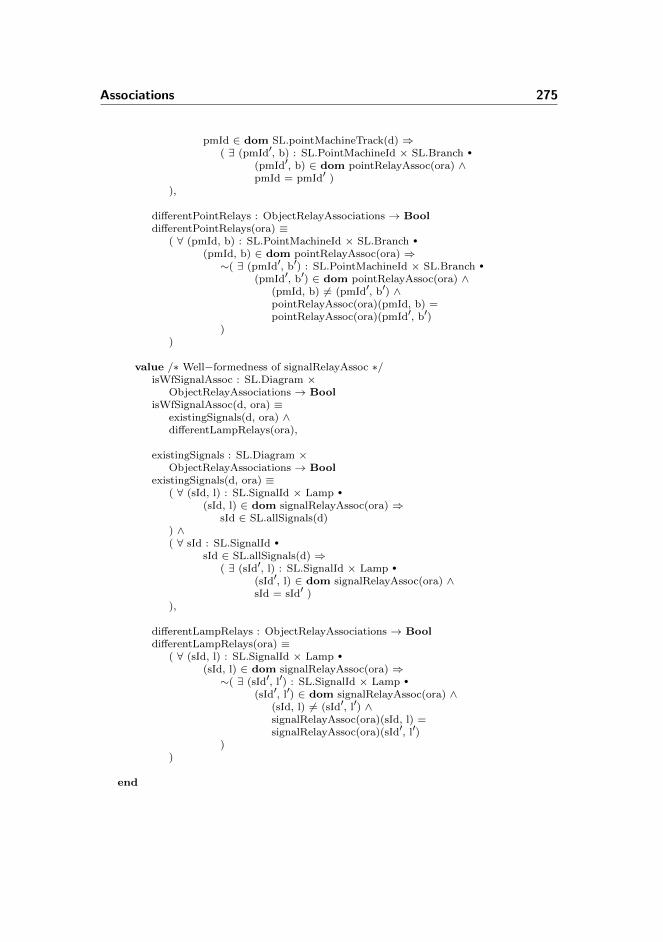
Associations 275
pmId ∈ dom SL.pointMachineTrack(d) ⇒( ∃ (pmId′, b) : SL.PointMachineId × SL.Branch •
(pmId′, b) ∈ dom pointRelayAssoc(ora) ∧pmId = pmId′ )
),
differentPointRelays : ObjectRelayAssociations → BooldifferentPointRelays(ora) ≡
( ∀ (pmId, b) : SL.PointMachineId × SL.Branch •
(pmId, b) ∈ dom pointRelayAssoc(ora) ⇒∼( ∃ (pmId′, b′) : SL.PointMachineId × SL.Branch •
(pmId′, b′) ∈ dom pointRelayAssoc(ora) ∧(pmId, b) 6= (pmId′, b′) ∧pointRelayAssoc(ora)(pmId, b) =pointRelayAssoc(ora)(pmId′, b′)
))
value /∗ Well−formedness of signalRelayAssoc ∗/isWfSignalAssoc : SL.Diagram ×
ObjectRelayAssociations → BoolisWfSignalAssoc(d, ora) ≡
existingSignals(d, ora) ∧differentLampRelays(ora),
existingSignals : SL.Diagram ×ObjectRelayAssociations → Bool
existingSignals(d, ora) ≡( ∀ (sId, l) : SL.SignalId × Lamp •
(sId, l) ∈ dom signalRelayAssoc(ora) ⇒sId ∈ SL.allSignals(d)
) ∧( ∀ sId : SL.SignalId •
sId ∈ SL.allSignals(d) ⇒( ∃ (sId′, l) : SL.SignalId × Lamp •
(sId′, l) ∈ dom signalRelayAssoc(ora) ∧sId = sId′ )
),
differentLampRelays : ObjectRelayAssociations → BooldifferentLampRelays(ora) ≡
( ∀ (sId, l) : SL.SignalId × Lamp •
(sId, l) ∈ dom signalRelayAssoc(ora) ⇒∼( ∃ (sId′, l′) : SL.SignalId × Lamp •
(sId′, l′) ∈ dom signalRelayAssoc(ora) ∧(sId, l) 6= (sId′, l′) ∧signalRelayAssoc(ora)(sId, l) =signalRelayAssoc(ora)(sId′, l′)
))
end
276 Specifications
E.3.3 Train Movement Associations
context: T, SL, TSscheme TrainMovementAssociations =
class
typeTrainMovementAssociations ::
connectionVars : (SL.TrackId × SL.TrackId) →m T.VarIdcounterVars : SL.TrackId →m T.VarIddirectionFwdVars : SL.TrackId →m T.VarIddirectionBwdVars : SL.TrackId →m T.VarIddirections : (SL.TrackId × SL.TrackId) →m T.Direction
value /∗ Auxiliary functions ∗/getConnectionVar : SL.TrackId × SL.TrackId ×
TrainMovementAssociations → TextgetConnectionVar(id, nb, tma) ≡
let conVars = connectionVars(tma)in if (id,nb) ∈ dom conVars
then conVars(id, nb) else conVars(nb, id) endend,
getCounterVar : SL.TrackId ×TrainMovementAssociations → T.VarId
getCounterVar(tId, tma) ≡counterVars(tma)(tId),
getFwdDirVar : SL.TrackId ×TrainMovementAssociations → T.VarId
getFwdDirVar(tId, tma) ≡ directionFwdVars(tma)(tId),
getBwdDirVar : SL.TrackId ×TrainMovementAssociations → T.VarId
getBwdDirVar(tId, tma) ≡ directionBwdVars(tma)(tId),
getDirVar : SL.TrackId × SL.TrackId ×TrainMovementAssociations → T.VarId
getDirVar(id, nb, tma) ≡getDirVar(id, directions(tma)(id, nb), tma),
getDirVar : SL.TrackId × SL.TrackId ×TrainMovementAssociations → T.VarId
getDirVar (id, nb, tma) ≡getDirVar(id, directions(tma)(nb, id), tma),
getDirVar : SL.TrackId × T.Direction ×TrainMovementAssociations → T.VarId
getDirVar(id, dir, tma) ≡if dir = T.fwd then getFwdDirVar(id, tma)else getBwdDirVar(id, tma) end,
getDirection : SL.TrackId × SL.TrackId ×TrainMovementAssociations → T.Direction

Associations 277
getDirection(tId1, tId2, tma) ≡let directions = directions(tma)in if (tId1, tId2) ∈ dom directions
then directions(tId1, tId2)else directions(tId2, tId1)end
end
value /∗ Well−formedness of train movement associations ∗/isWfTrainMovementAssociations : SL.Diagram ×
TrainMovementAssociations → BoolisWfTrainMovementAssociations(d, tma) ≡
noRelayVariableOverlap(tma) ∧isWfConnectionVars(d, tma) ∧isWfCounterVars(d, tma) ∧isWfDirectionFwdVars(d, tma) ∧isWfDirectionBwdVars(d, tma) ∧isWfDirections(d, tma),
noRelayVariableOverlap : TrainMovementAssociations → BoolnoRelayVariableOverlap(tma) ≡
let connectionVars = rng connectionVars(tma),counterVars = rng counterVars(tma),directionFwdVars = rng directionFwdVars(tma),directionBwdVars = rng directionBwdVars(tma)
in connectionVars ∩ counterVars = {} ∧connectionVars ∩ directionFwdVars = {} ∧connectionVars ∩ directionBwdVars = {} ∧counterVars ∩ directionFwdVars = {} ∧counterVars ∩ directionBwdVars = {} ∧directionFwdVars ∩ directionBwdVars = {}
end
valueisWfConnectionVars : SL.Diagram ×
TrainMovementAssociations → BoolisWfConnectionVars(d, tma) ≡
conVarsValidDomain(d, tma) ∧conVarsValidRange(connectionVars(tma)),
conVarsValidDomain : SL.Diagram ×TrainMovementAssociations → Bool
conVarsValidDomain(d, tma) ≡(∀ (tId1, tId2) : (SL.TrackId × SL.TrackId) •
(tId1, tId2) ∈ dom connectionVars(tma) ⇒SL.areNeighbours(tId1, tId2, d) ),
conVarsValidRange : ((SL.TrackId × SL.TrackId) →m T.VarId) → BoolconVarsValidRange(connectionVars) ≡
(∀ key : (SL.TrackId × SL.TrackId) •
key ∈ dom connectionVars ⇒∼( ∃ key′ : (SL.TrackId × SL.TrackId) •
key′ ∈ dom connectionVars ∧key 6= key′ ∧connectionVars(key) =

278 Specifications
connectionVars(key′) ))
valueisWfCounterVars : SL.Diagram ×
TrainMovementAssociations → BoolisWfCounterVars(d, tma) ≡
cntVarsValidDomain(d, tma) ∧cntVarsValidRange(counterVars(tma)),
cntVarsValidDomain : SL.Diagram ×TrainMovementAssociations → Bool
cntVarsValidDomain(d, tma) ≡let allTrackSections = SL.allLinears(d) ∪ SL.allPoints(d)in dom counterVars(tma) = allTrackSectionsend,
cntVarsValidRange : (SL.TrackId →m T.VarId) → BoolcntVarsValidRange(counterVars) ≡
(∀ key : SL.TrackId •
key ∈ dom counterVars ⇒∼( ∃ key′ : SL.TrackId •
key′ ∈ dom counterVars ∧key 6= key′ ∧counterVars(key) =counterVars(key′) )
)
valueisWfDirectionFwdVars : SL.Diagram ×
TrainMovementAssociations → BoolisWfDirectionFwdVars(d, tma) ≡
fwdVarsValidDomain(d, tma) ∧fwdVarsValidRange(directionFwdVars(tma)),
fwdVarsValidDomain : SL.Diagram ×TrainMovementAssociations → Bool
fwdVarsValidDomain(d, tma) ≡let allTrackSections = SL.allLinears(d) ∪ SL.allPoints(d)in dom directionFwdVars(tma) = allTrackSectionsend,
fwdVarsValidRange : (SL.TrackId →m T.VarId) → BoolfwdVarsValidRange(directionFwdVars) ≡
(∀ key : SL.TrackId •
key ∈ dom directionFwdVars ⇒∼( ∃ key′ : SL.TrackId •
key′ ∈ dom directionFwdVars ∧key 6= key′ ∧directionFwdVars(key) =directionFwdVars(key′) )
)
valueisWfDirectionBwdVars : SL.Diagram ×

Associations 279
TrainMovementAssociations → BoolisWfDirectionBwdVars(d, tma) ≡
bwdVarsValidDomain(d, tma) ∧bwdVarsValidRange(directionBwdVars(tma)),
bwdVarsValidDomain : SL.Diagram ×TrainMovementAssociations → Bool
bwdVarsValidDomain(d, tma) ≡let allTrackSections = SL.allLinears(d) ∪ SL.allPoints(d)in dom directionBwdVars(tma) = allTrackSectionsend,
bwdVarsValidRange : (SL.TrackId →m T.VarId) → BoolbwdVarsValidRange(directionBwdVars) ≡
(∀ key : SL.TrackId •
key ∈ dom directionBwdVars ⇒∼( ∃ key′ : SL.TrackId •
key′ ∈ dom directionBwdVars ∧key 6= key′ ∧directionBwdVars(key) =directionBwdVars(key′) )
)
valueisWfDirections : SL.Diagram ×
TrainMovementAssociations → BoolisWfDirections(d, tma) ≡
directionsValidDomain(d, tma) ∧bothDirections(directions(tma)),
directionsValidDomain : SL.Diagram ×TrainMovementAssociations → Bool
directionsValidDomain(d, tma) ≡(∀ (tId1, tId2) : (SL.TrackId × SL.TrackId) •
(tId1, tId2) ∈ dom directions(tma) ⇒SL.areNeighbours(tId1, tId2, d) ),
bothDirections :((SL.TrackId × SL.TrackId) →m T.Direction) → Bool
bothDirections(directions) ≡( ∀ (tId1, tId2) : (SL.TrackId × SL.TrackId) •
(tId1, tId2) ∈ dom directions ⇒( ∃ (tId1′, tId2′) : (SL.TrackId × SL.TrackId) •
(tId1′, tId2′) ∈ dom directions ∧tId1 = tId2′ ∧ tId2 = tId1′ ∧directions((tId1, tId2)) 6=directions((tId1′, tId2′))
))
end

280 Specifications
E.4 Misc.
E.4.1 Objects
context: Typesobject T : Types
context: Unparserobject UP : Unparser
E.4.2 Types
scheme Types =class
typeVarId = Text,TrainRouteId = Text,
PointsState == plus | minus | arbitrary,
/∗ a boolean expression ∗/BooleanExp ==
and(a : BooleanExp-set) |or(o : BooleanExp-set) |neg(n : BooleanExp) |lessthan(ArithmeticExp, ArithmeticExp) |greaterthan(ArithmeticExp, ArithmeticExp) |geq(ArithmeticExp, ArithmeticExp) | /∗ greater than equal to∗/equals(ArithmeticExp, ArithmeticExp) |literal(id : VarId) |bool(b : Bool),
/∗ an arithmetric expression ∗/ArithmeticExp ==
add(a : ArithmeticExp-set) |sub(s : ArithmeticExp-set) |literal(l : VarId),
AssignExp ==BoolAssign(ba : Bool) |NatAssign(na : Nat) |AddAssign(aa : Nat) |SubAssign(sa : Nat) ,
Direction == fwd | bwd
value

Misc. 281
oppositeDirection : Direction → DirectionoppositeDirection(dir) ≡
case dir offwd → bwd,bwd → fwd
end
typeLTLformula ==
b(bExp : BooleanExp) |ltrl(l : Text) | /∗ Literal ∗/conj(LTLformula-set) | /∗ Conjunction ∗/disj(LTLformula-set) | /∗ Disjunction ∗/paren(LTLformula) | /∗ Parenthesis ∗/neg(LTLformula) | /∗ Negation ∗/impl(LTLformula, LTLformula) | /∗ Implication ∗/x(LTLformula) | /∗ Next ∗/g(LTLformula) | /∗ Globally ∗/f(LTLformula) | /∗ Finally ∗/u(LTLformula, LTLformula) /∗ Until ∗/
end
E.4.3 Unparser
context: T, TSscheme Unparser =
classvalue /∗ Functions to be called externally ∗/
/∗ Unparses given transition system ∗/print : TS.TransitionSystem → Textprint(ts) ≡
let name = TS.name(ts),state = TS.state(ts),transitionRules = TS.transitionRules(ts),assertions = TS.assertions(ts)
in ′′\ntransition_system\n\n[′′ name ′′]\n\nlocal′′ print(state) ′′\n\nin\n′′ print(transitionRules) ′′\n\nend\n\nltl_assertion\n′′ print(name, assertions) ′′\n′′
end
value /∗ Auxiliary functions ∗/
/∗ Converts a boolean value to text ∗/toString : Bool → TexttoString(b) ≡ if b then ′′true′′ else ′′false′′ end,
/∗ Converts a natural number to text ∗/toString : Nat → TexttoString(n) ≡

282 Specifications
case n of0 → ′′0′′,1 → ′′1′′,2 → ′′2′′,3 → ′′3′′,4 → ′′4′′
end
value /∗ Unparse state ∗/
/∗ State ∗/print : TS.Var-set → Textprint(vars) ≡
if vars = {} then ′′′′ elselet var = hd vars, vars′ = vars \ {var}in ′′\n′′ print(var)
if vars′ = {} then ′′′′
else ′′,′′ print(vars′)end
endend,
/∗ State variable ∗/print : TS.Var → Textprint(var) ≡
let id = TS.id(var),val = TS.val(var)
in id ′′ : ′′ print(val)end,
/∗ Val ∗/print : TS.Val → Textprint(val) ≡
case val ofTS.mk BoolVal(b) → ′′Bool := ′′ toString(b),TS.mk NatVal(n) → ′′Nat := ′′ toString(n)
end
value /∗ Unparse transition rules ∗/
/∗ Transition rules ∗/print : TS.TransitionRule-set → Textprint(trs) ≡
if trs = {} then ′′′′
else let tr = hd trs, trs′ = trs \ {tr}in ′′\n′′ print(tr)
if trs′ = {} then ′′′′
else ′′\n[=]′′ print(trs′)end
endend,
/∗ Transition rule ∗/print : TS.TransitionRule → Textprint(tr) ≡

Misc. 283
′′[′′ TS.name(tr) ′′]\n′′ print(TS.guard(tr)) ′′ ==>\n′′ print(TS.assignments(tr)),
/∗ Multiple assignment ∗/print : TS.MultipleAssignment → Textprint(assignments) ≡
if assignments = {} then ′′′′ elselet assignment = hd assignments,
assignments′ = assignments \ {assignment}in print(assignment)
if assignments′ = {} then ′′′′
else ′′, ′′ print(assignments′)end
endend,
/∗ Assignment ∗/print : TS.Assignment → Textprint(assignment) ≡
let id = TS.id(assignment)in case TS.assign(assignment) of
T.BoolAssign(b) → id ′′’ = ′′ toString(b),T.NatAssign(n) → id ′′’ = ′′ toString(n),T.AddAssign(a) → id ′′’ = ′′ id ′′ + ′′ toString(a),T.SubAssign(s) → id ′′’ = ′′ id ′′ - ′′ toString(s)
endend
value /∗ Unparse assertions ∗/print : Text × TS.Assertion-set → Textprint(tsName, asserts) ≡
if asserts = {} then ′′′′ elselet assert = hd asserts, asserts′ = asserts \ {assert}in ′′\n′′ print(tsName, assert)
if asserts′ = {} then ′′′′
else ′′,\n′′ print(tsName, asserts′)end
endend,
/∗ Assertion ∗/print : Text × (Text × T.LTLformula) → Textprint(tsName, (nm, ltl)) ≡
′′[′′ nm ′′] ′′ tsName ′′ |-\n′′ print(ltl)
value /∗ Unparse expressions ∗/print : T.BooleanExp → Textprint(boolExp) ≡
case boolExp ofT.and(a) → let x = hd a, a′ = a \ {x}
in print(x) if a′ = {} then ′′′′
else ′′ /\\ ′′ print(T.and(a′)) endend,

284 Specifications
T.or(o) → let x = hd o, o′ = o \ {x}in print(x)
if o′ = {} then ′′′′
else ′′ \\/ ′′ print(T.or(o′)) endend,
T.neg(n) → ′′~(′′ print(n) ′′)′′,T.lessthan(l,r) → print(l) ′′ < ′′ print(r),T.greaterthan(l,r) → print(l) ′′ > ′′ print(r),T.geq(l,r) → print(l) ′′ >= ′′ print(r),T.equals(l,r) → print(l) ′′ = ′′ print(r),T.literal(l) → l,T.bool(b) → toString(b)
end,
print : T.ArithmeticExp → Textprint(arithExp) ≡
case arithExp ofT.add(a) → let x = hd a, a′ = a \ {x}
in print(x) if a′ = {} then ′′′′
else ′′ + ′′ print(T.add(a′))end
end,T.sub(s) → let x = hd s, s′ = s \ {x}
in print(x) if s′ = {} then ′′′′
else ′′ - ′′ print(T.sub(s′))end
end,T.literal(n) → n
end
value /∗ Unparse LTL formula ∗/print : T.LTLformula → Textprint(ltl) ≡
case ltl ofT.paren(ltl) → ′′(′′ print(ltl) ′′)′′,T.b(b) → print(b),T.ltrl(l) → l,T.conj(set) → let s = hd set, set′ = set \ {s}
in if set′ = {} then ′′′′
else print(T.conj(set′)) ′′ /\\ ′′
end print(s)end,
T.disj(set) → let s = hd set, set′ = set \ {s}in if set′ = {} then ′′′′
else print(T.disj(set′)) ′′ \\/ ′′
end print(s)end,
T.neg(n) → ′′~(′′ print(n) ′′)′′,T.impl(l,r) → print(l) ′′ => ′′ print(r),T.x(x) → ′′X(′′ print(x) ′′)′′,T.g(g) → ′′G(′′ print(g) ′′)′′,T.f(f) → ′′F(′′ print(f) ′′)′′,T.u(l,r) → ′′U(′′ print(l) ′′, ′′ print(r) ′′)′′
end

Misc. 285
end
E.4.4 Station Template
context: G, UP, ORAscheme StationTemplate =
classvalue - - Station Layout Diagram
stationLayoutDiagram : SL.Diagram =SL.mk Diagram(
line, allLinears, allPoints, allSignals,neighbours, branchNeighbours, pointMachineTrack,trackPointMachine, signalLocations),
line : Text = ′′line′′,allLinears : SL.TrackId-set = {},allPoints : SL.TrackId-set = {},allSignals : SL.SignalId-set = {},neighbours : (SL.TrackId × SL.TrackId)-set = {},branchNeighbours :
(SL.TrackId × SL.TrackId) →m SL.Branch = [ ],pointMachineTrack : SL.PointMachineId →m SL.TrackId =
[ ],trackPointMachine : SL.TrackId →m SL.PointMachineId =
[ ],signalLocations :
(SL.TrackId × SL.TrackId) →m SL.SignalId = [ ]
value - - Train Route TabletrainRouteTable : TRT.TrainRouteTable = [ ],dataRow : TRT.DataRow =
TRT.mk DataRow({}, [ ], [ ], [ ], (), (), [ ])
value - - Interlocking PlaninterlockingPlan : IP.InterlockingPlan =
IP.mk InterlockingPlan(stationLayoutDiagram, trainRouteTable)
value - - ButtonsallButtons : Text-set = {}
value - - Object Relay AssociationsobjectRelayAssociations : ORA.ObjectRelayAssociations =
ORA.mk ObjectRelayAssociations(routeRelayAssoc, trackRelayAssoc,pointRelayAssoc, signalRelayAssoc),
routeRelayAssoc : T.TrainRouteId →m T.VarId = [ ],trackRelayAssoc : SL.TrackId →m T.VarId = [ ],pointRelayAssoc :
SL.PointMachineId × SL.Branch →m T.VarId = [ ],signalRelayAssoc :
SL.SignalId × ORA.Lamp →m T.VarId = [ ]

286 Specifications
test case - - Well-formedness checks[ isWfStationLayoutDiagram ]
SL.isWfDiagram(stationLayoutDiagram),[ isWfTrainRouteTable ]
TRT.isWfTrainRouteTable(trainRouteTable,stationLayoutDiagram),
[ isWfInterlockingPlan ]IP.isWfInterlockingPlan(interlockingPlan),
[ isWfObjectRelayAssociations ]ORA.isWfObjectRelayAssociations(objectRelayAssociations,
interlockingPlan)
test case[ generate transitionSystem ]
UP.print(G.generate(′′InterlockingSystem′′,objectRelayAssociations,interlockingPlan,allButtons))
end
E.4.5 Stenstrup Station
context: G, UPscheme Stenstrup =
classvalue
stenstrupSLD : SL.Diagram =SL.mk Diagram(
′′line′′,allLinears,allPoints,allSignals,neighbours,branchNeighbours,pointMachineTrack,trackPointMachine,signalLocations
),
allLinears : SL.TrackId-set = {′′A12′′, ′′02′′, ′′04′′, ′′B12′′},allPoints : SL.TrackId-set = {′′01′′, ′′03′′},allSignals : SL.SignalId-set = {′′A′′, ′′B′′, ′′E′′, ′′F′′, ′′G′′, ′′H′′},
neighbours : (SL.TrackId × SL.TrackId)-set ={ (′′line′′, ′′A12′′), (′′A12′′, ′′01′′),
(′′01′′, ′′02′′), (′′01′′, ′′04′′),(′′02′′, ′′03′′), (′′03′′, ′′04′′),(′′03′′, ′′B12′′), (′′B12′′, ′′line′′) },
branchNeighbours : (SL.TrackId × SL.TrackId) →m SL.Branch =

Misc. 287
[ (′′01′′, ′′02′′) 7→ T.plus,(′′01′′, ′′04′′) 7→ T.minus,(′′03′′, ′′02′′) 7→ T.plus,(′′03′′, ′′04′′) 7→ T.minus ],
pointMachineTrack : SL.PointMachineId →m SL.TrackId =[ ′′01′′ 7→ ′′01′′,
′′02′′ 7→ ′′03′′ ],
trackPointMachine : SL.TrackId →m SL.PointMachineId =[ ′′01′′ 7→ ′′01′′,
′′03′′ 7→ ′′02′′ ],
signalLocations : (SL.TrackId × SL.TrackId) →m SL.SignalId =[ (′′line′′, ′′A12′′) 7→ ′′A′′, (′′line′′, ′′B12′′) 7→ ′′B′′,
(′′02′′, ′′01′′) 7→ ′′E′′, (′′04′′, ′′01′′) 7→ ′′F′′,(′′02′′, ′′03′′) 7→ ′′G′′, (′′04′′, ′′03′′) 7→ ′′H′′ ]
valueallButtons : Text-set = {′′b00406′′, ′′b03106′′, ′′b00606′′, ′′b03306′′}
valuestenstrupTRT : TRT.TrainRouteTable =
[ ′′2′′ 7→ dataRow2, ′′3′′ 7→ dataRow3,′′5′′ 7→ dataRow5, ′′6′′ 7→ dataRow6,′′7′′ 7→ dataRow7, ′′8′′ 7→ dataRow8,′′9′′ 7→ dataRow9, ′′10′′ 7→ dataRow10 ],
dataRow2 : TRT.DataRow =TRT.mk DataRow({′′03′′, ′′B12′′},[ ′′A′′ 7→ TRT.gr, ′′B′′ 7→ TRT.arbitrary, ′′E′′ 7→ TRT.arbitrary,
′′F′′ 7→ TRT.re, ′′G′′ 7→ TRT.re, ′′H′′ 7→ TRT.arbitrary ],[ ′′01′′ 7→ T.plus, ′′02′′ 7→ T.plus ],[ ′′A12′′ 7→ true, ′′01′′ 7→ true, ′′02′′ 7→ true,
′′04′′ 7→ false, ′′03′′ 7→ true, ′′B12′′ 7→ true ],( ′′A′′, ′′A12′′ ),( ((′′01′′, TRT.dropped), (′′02′′, TRT.drawn)),
((′′02′′, TRT.dropped), (′′01′′, TRT.drawn)) ),[ ′′2′′ 7→ true, ′′3′′ 7→ true, ′′5′′ 7→ true, ′′6′′ 7→ true,
′′7′′ 7→ true, ′′8′′ 7→ true, ′′9′′ 7→ false, ′′10′′ 7→ true ]),
dataRow3 : TRT.DataRow =TRT.mk DataRow({′′03′′, ′′B12′′},[ ′′A′′ 7→ TRT.gr, ′′B′′ 7→ TRT.arbitrary, ′′E′′ 7→ TRT.re,
′′F′′ 7→ TRT.arbitrary, ′′G′′ 7→ TRT.arbitrary, ′′H′′ 7→ TRT.re ],[ ′′01′′ 7→ T.minus, ′′02′′ 7→ T.minus ],[ ′′A12′′ 7→ true, ′′01′′ 7→ true, ′′02′′ 7→ false,
′′04′′ 7→ true, ′′03′′ 7→ true, ′′B12′′ 7→ true ],( ′′A′′, ′′A12′′ ),( ((′′01′′, TRT.dropped), (′′04′′, TRT.drawn)),
((′′04′′, TRT.dropped), (′′01′′, TRT.drawn)) ),[ ′′2′′ 7→ true, ′′3′′ 7→ true, ′′5′′ 7→ true, ′′6′′ 7→ true,

288 Specifications
′′7′′ 7→ true, ′′8′′ 7→ true, ′′9′′ 7→ true, ′′10′′ 7→ false ]),
dataRow5 : TRT.DataRow =TRT.mk DataRow({′′A12′′, ′′01′′},[ ′′A′′ 7→ TRT.arbitrary, ′′B′′ 7→ TRT.gr, ′′E′′ 7→ TRT.re,
′′F′′ 7→ TRT.arbitrary, ′′G′′ 7→ TRT.arbitrary, ′′H′′ 7→ TRT.re ],[ ′′01′′ 7→ T.plus, ′′02′′ 7→ T.plus ],[ ′′A12′′ 7→ true, ′′01′′ 7→ true, ′′02′′ 7→ true,
′′04′′ 7→ false, ′′03′′ 7→ true, ′′B12′′ 7→ true ],( ′′B′′, ′′B12′′ ),( ((′′03′′, TRT.dropped), (′′02′′, TRT.drawn)),
((′′02′′, TRT.dropped), (′′03′′, TRT.drawn)) ),[ ′′2′′ 7→ true, ′′3′′ 7→ true, ′′5′′ 7→ true, ′′6′′ 7→ true,
′′7′′ 7→ false, ′′8′′ 7→ true, ′′9′′ 7→ true, ′′10′′ 7→ true ]),
dataRow6 : TRT.DataRow =TRT.mk DataRow({′′A12′′, ′′01′′},[ ′′A′′ 7→ TRT.arbitrary, ′′B′′ 7→ TRT.gr, ′′E′′ 7→ TRT.arbitrary,
′′F′′ 7→ TRT.re, ′′G′′ 7→ TRT.re, ′′H′′ 7→ TRT.arbitrary ],[ ′′01′′ 7→ T.minus, ′′02′′ 7→ T.minus ],[ ′′A12′′ 7→ true, ′′01′′ 7→ true, ′′02′′ 7→ false,
′′04′′ 7→ true, ′′03′′ 7→ true, ′′B12′′ 7→ true ],( ′′B′′, ′′B12′′ ),( ((′′03′′, TRT.dropped), (′′04′′, TRT.drawn)),
((′′04′′, TRT.dropped), (′′03′′, TRT.drawn)) ),[ ′′2′′ 7→ true, ′′3′′ 7→ true, ′′5′′ 7→ true, ′′6′′ 7→ true,
′′7′′ 7→ true, ′′8′′ 7→ false, ′′9′′ 7→ true, ′′10′′ 7→ true ]),
dataRow7 : TRT.DataRow =TRT.mk DataRow({},[ ′′A′′ 7→ TRT.arbitrary, ′′B′′ 7→ TRT.arbitrary, ′′E′′ 7→ TRT.gr,
′′F′′ 7→ TRT.re, ′′G′′ 7→ TRT.arbitrary, ′′H′′ 7→ TRT.arbitrary ],[ ′′01′′ 7→ T.plus, ′′02′′ 7→ T.arbitrary ],[ ′′A12′′ 7→ true, ′′01′′ 7→ true, ′′02′′ 7→ false,
′′04′′ 7→ false, ′′03′′ 7→ false, ′′B12′′ 7→ false ],( ′′E′′, ′′01′′ ),( ((′′01′′, TRT.dropped), (′′A12′′, TRT.drawn)),
((′′A12′′, TRT.dropped), (′′01′′, TRT.drawn)) ),[ ′′2′′ 7→ true, ′′3′′ 7→ true, ′′5′′ 7→ false, ′′6′′ 7→ true,
′′7′′ 7→ true, ′′8′′ 7→ true, ′′9′′ 7→ false, ′′10′′ 7→ false ]),
dataRow8 : TRT.DataRow =TRT.mk DataRow({},[ ′′A′′ 7→ TRT.arbitrary, ′′B′′ 7→ TRT.arbitrary, ′′E′′ 7→ TRT.re,
′′F′′ 7→ TRT.gr, ′′G′′ 7→ TRT.arbitrary, ′′H′′ 7→ TRT.arbitrary ],[ ′′01′′ 7→ T.minus, ′′02′′ 7→ T.arbitrary ],[ ′′A12′′ 7→ true, ′′01′′ 7→ true, ′′02′′ 7→ false,
Misc. 289
′′04′′ 7→ false, ′′03′′ 7→ false, ′′B12′′ 7→ false ],( ′′F′′, ′′01′′ ),( ((′′01′′, TRT.dropped), (′′A12′′, TRT.drawn)),
((′′A12′′, TRT.dropped), (′′01′′, TRT.drawn)) ),[ ′′2′′ 7→ true, ′′3′′ 7→ true, ′′5′′ 7→ true, ′′6′′ 7→ false,
′′7′′ 7→ true, ′′8′′ 7→ true, ′′9′′ 7→ false, ′′10′′ 7→ false ]),
dataRow9 : TRT.DataRow =TRT.mk DataRow({},[ ′′A′′ 7→ TRT.arbitrary, ′′B′′ 7→ TRT.arbitrary, ′′E′′ 7→ TRT.arbitrary,
′′F′′ 7→ TRT.arbitrary, ′′G′′ 7→ TRT.gr, ′′H′′ 7→ TRT.re ],[ ′′01′′ 7→ T.arbitrary, ′′02′′ 7→ T.plus ],[ ′′A12′′ 7→ false, ′′01′′ 7→ false, ′′02′′ 7→ false,
′′04′′ 7→ false, ′′03′′ 7→ true, ′′B12′′ 7→ true ],( ′′G′′, ′′03′′ ),( ((′′03′′, TRT.dropped), (′′B12′′, TRT.drawn)),
((′′B12′′, TRT.dropped), (′′03′′, TRT.drawn)) ),[ ′′2′′ 7→ false, ′′3′′ 7→ true, ′′5′′ 7→ true, ′′6′′ 7→ true,
′′7′′ 7→ false, ′′8′′ 7→ false, ′′9′′ 7→ true, ′′10′′ 7→ true ]),
dataRow10 : TRT.DataRow =TRT.mk DataRow({},[ ′′A′′ 7→ TRT.arbitrary, ′′B′′ 7→ TRT.arbitrary, ′′E′′ 7→ TRT.arbitrary,
′′F′′ 7→ TRT.arbitrary, ′′G′′ 7→ TRT.re, ′′H′′ 7→ TRT.gr ],[ ′′01′′ 7→ T.arbitrary, ′′02′′ 7→ T.minus ],[ ′′A12′′ 7→ false, ′′01′′ 7→ false, ′′02′′ 7→ false,
′′04′′ 7→ false, ′′03′′ 7→ true, ′′B12′′ 7→ true ],( ′′H′′, ′′03′′ ),( ((′′03′′, TRT.dropped), (′′B12′′, TRT.drawn)),
((′′B12′′, TRT.dropped), (′′03′′, TRT.drawn)) ),[ ′′2′′ 7→ true, ′′3′′ 7→ false, ′′5′′ 7→ true, ′′6′′ 7→ true,
′′7′′ 7→ false, ′′8′′ 7→ false, ′′9′′ 7→ true, ′′10′′ 7→ true ])
valuestenstrupIP : IP.InterlockingPlan =
IP.mk InterlockingPlan(stenstrupSLD,stenstrupTRT
)
valuestenstrupAssocs : ORA.ObjectRelayAssociations =
ORA.mk ObjectRelayAssociations(routeRelayAssoc,trackRelayAssoc,pointRelayAssoc,signalRelayAssoc
),
routeRelayAssoc : T.TrainRouteId →m T.VarId =

290 Specifications
[ ′′2′′ 7→ ′′ia′′, ′′3′′ 7→ ′′ia′′,′′5′′ 7→ ′′ib′′, ′′6′′ 7→ ′′ib′′,′′7′′ 7→ ′′ua′′, ′′8′′ 7→ ′′ua′′,′′9′′ 7→ ′′ub′′, ′′10′′ 7→ ′′ub′′ ],
trackRelayAssoc : SL.TrackId →m T.VarId =[ ′′A12′′ 7→ ′′a12′′, ′′01′′ 7→ ′′t01′′, ′′02′′ 7→ ′′t02′′,
′′B12′′ 7→ ′′b12′′, ′′03′′ 7→ ′′t03′′, ′′04′′ 7→ ′′t04′′ ],
pointRelayAssoc : SL.PointMachineId ×SL.Branch →m T.VarId =[ (′′01′′, T.plus) 7→ ′′plus01′′, (′′01′′, T.minus) 7→ ′′minus01′′,
(′′02′′, T.plus) 7→ ′′plus02′′, (′′02′′, T.minus) 7→ ′′minus02′′ ],
signalRelayAssoc : SL.SignalId × ORA.Lamp →m T.VarId =[ (′′A′′, ORA.gr) 7→ ′′aGreen′′, (′′A′′, ORA.re) 7→ ′′aRed′′,
(′′B′′, ORA.gr) 7→ ′′bGreen′′, (′′B′′, ORA.re) 7→ ′′bRed′′,(′′E′′, ORA.gr) 7→ ′′eGreen′′, (′′E′′, ORA.re) 7→ ′′eRed′′,(′′F′′, ORA.gr) 7→ ′′fGreen′′, (′′F′′, ORA.re) 7→ ′′fRed′′,(′′G′′, ORA.gr) 7→ ′′gGreen′′, (′′G′′, ORA.re) 7→ ′′gRed′′,(′′H′′, ORA.gr) 7→ ′′hGreen′′, (′′H′′, ORA.re) 7→ ′′hRed′′ ]
test case - - Well-formedness checks[ isWfStationLayoutDiagram ]
SL.isWfDiagram(stenstrupSLD),[ isWfTrainRouteTable ]
TRT.isWfTrainRouteTable(stenstrupTRT, stenstrupSLD),[ isWfInterlockingPlan ]
IP.isWfInterlockingPlan(stenstrupIP),[ isWfObjectRelayAssociations ]
ORA.isWfObjectRelayAssociations(stenstrupAssocs, stenstrupIP)
test case[ generate transitionSystem ]
UP.print(G.generate(′′InterlockingSystem′′,stenstrupAssocs,stenstrupIP,allButtons))
end
E.5 Test
E.5.1 Test of Station Layout
context: SLscheme Test StationLayout =
classvalue
Test 291
/∗ Fail test cases ∗//∗ Well−formedness NEIGHBOURS start ∗//∗ id which is not a section id ∗/neighbours OnlySections d fail : SL.Diagram =
SL.mk Diagram(′′line′′, allLinears, allPoints, allSignals,neighbours OnlySections fail, branchNeighbours,pmt, tpm, signalLocations),
neighbours OnlySections fail :(SL.TrackId × SL.TrackId)-set ={(′′01′′, ′′02′′), (′′01′′, ′′A′′)},
/∗ id which is a section id ∗/neighbours OnlySections d succeed : SL.Diagram =
SL.mk Diagram(′′line′′, allLinears, allPoints, allSignals,neighbours OnlySections succeed,branchNeighbours, pmt, tpm, signalLocations),
neighbours OnlySections succeed :(SL.TrackId × SL.TrackId)-set ={(′′01′′, ′′02′′), (′′01′′, ′′03′′)},
/∗ a section without a neighbour ∗/neighbours EverySection d fail : SL.Diagram =
SL.mk Diagram(′′line′′, allLinears, allPoints, allSignals,neighbours EverySection fail, branchNeighbours,pmt, tpm, signalLocations),
neighbours EverySection fail :(SL.TrackId × SL.TrackId)-set = {(′′01′′, ′′02′′)},
/∗ all sections has a neighbour, 01 is connectedto line otherwisethe station is jsut planted in the middle ofno−where.∗/neighbours EverySection d succeed : SL.Diagram =
SL.mk Diagram(′′line′′, allLinears, allPoints, allSignals,neighbours EverySection succeed,branchNeighbours, pmt, tpm, signalLocations),
neighbours EverySection succeed :(SL.TrackId × SL.TrackId)-set ={(′′line′′, ′′01′′), (′′01′′, ′′02′′), (′′01′′, ′′03′′)},
/∗ a linear section neighbour with itself ∗/neighbours Irreflexive d linear fail : SL.Diagram =
SL.mk Diagram(′′line′′, allLinears, allPoints, allSignals,neighbours Irreflexive linear fail,branchNeighbours, pmt, tpm, signalLocations),
neighbours Irreflexive linear fail :(SL.TrackId × SL.TrackId)-set = {(′′03′′, ′′03′′)},

292 Specifications
/∗ a points section neighbour with itself ∗/neighbours Irreflexive d points fail : SL.Diagram =
SL.mk Diagram(′′line′′, allLinears, allPoints, allSignals,neighbours Irreflexive points fail,branchNeighbours, pmt, tpm, signalLocations),
neighbours Irreflexive points fail :(SL.TrackId × SL.TrackId)-set = {(′′01′′, ′′01′′)},
/∗ neighbouring sections are inserted as doubleentry ∗/neighbours Antisymmetrical d fail : SL.Diagram =
SL.mk Diagram(′′line′′, allLinears, allPoints, allSignals,neighbours Antisymmetrical fail,branchNeighbours, pmt, tpm, signalLocations),
neighbours Antisymmetrical fail :(SL.TrackId × SL.TrackId)-set ={(′′01′′, ′′02′′), (′′01′′, ′′03′′), (′′02′′, ′′01′′),(′′03′′, ′′01′′)},
/∗ neighbouring sections are inserted not as doubleentry ∗/neighbours Antisymmetrical d succeed : SL.Diagram =
SL.mk Diagram(′′line′′, allLinears, allPoints, allSignals,neighbours Antisymmetrical succeed,branchNeighbours, pmt, tpm, signalLocations),
neighbours Antisymmetrical succeed :(SL.TrackId × SL.TrackId)-set ={(′′01′′, ′′02′′), (′′01′′, ′′03′′)},
/∗ linear section 03 has no neighbours ∗/linears 1or2Neighbours d fail 1 : SL.Diagram =
SL.mk Diagram(′′line′′, allLinears linears 1or2Neighbours fail 2,allPoints, allSignals,neighbours linears 1or2Neighbours fail 1,branchNeighbours, pmt, tpm, signalLocations),
neighbours linears 1or2Neighbours fail 1 :(SL.TrackId × SL.TrackId)-set = {(′′01′′, ′′02′′)},
/∗ linear section 02 has 3 neighbours ∗/linears 1or2Neighbours d fail 2 : SL.Diagram =
SL.mk Diagram(′′line′′, allLinears linears 1or2Neighbours fail 2,allPoints, allSignals,neighbours linears 1or2Neighbours fail 2,branchNeighbours, pmt, tpm, signalLocations),
Test 293
allLinears linears 1or2Neighbours fail 2 :SL.TrackId-set = {′′02′′, ′′03′′, ′′04′′},
neighbours linears 1or2Neighbours fail 2 :(SL.TrackId × SL.TrackId)-set ={(′′01′′, ′′02′′), (′′03′′, ′′02′′), (′′04′′, ′′02′′)},
/∗ linear sections has 1 neighbour each ∗/linears 1or2Neighbours d succeed 1 : SL.Diagram =
SL.mk Diagram(′′line′′, allLinears, allPoints, allSignals,neighbours linears 1or2Neighbours succeed 1,branchNeighbours, pmt, tpm, signalLocations),
neighbours linears 1or2Neighbours succeed 1 :(SL.TrackId × SL.TrackId)-set ={(′′01′′, ′′02′′), (′′01′′, ′′03′′)},
/∗ linear sections has 2 neighbour each ∗/linears 1or2Neighbours d succeed 2 : SL.Diagram =
SL.mk Diagram(′′line′′,allLinears linears 1or2Neighbours succeed 2,allPoints, allSignals,neighbours linears 1or2Neighbours succeed 2,branchNeighbours, pmt, tpm, signalLocations),
allLinears linears 1or2Neighbours succeed 2 :SL.TrackId-set = {′′02′′, ′′03′′, ′′04′′, ′′05′′},
neighbours linears 1or2Neighbours succeed 2 :(SL.TrackId × SL.TrackId)-set ={(′′01′′, ′′02′′), (′′01′′, ′′03′′), (′′02′′, ′′04′′),(′′03′′, ′′05′′)},
/∗ point section 01 has 2 neighbours ∗/points 3Neighbours d fail 1 : SL.Diagram =
SL.mk Diagram(′′line′′, allLinears, allPoints, allSignals,neighbours points 3Neighbours fail 1,branchNeighbours, pmt, tpm, signalLocations),
neighbours points 3Neighbours fail 1 :(SL.TrackId × SL.TrackId)-set ={(′′01′′, ′′02′′), (′′01′′, ′′03′′)},
/∗ point section 01 has 4 neighbours ∗/points 3Neighbours d fail 2 : SL.Diagram =
SL.mk Diagram(′′line′′, allLinears points 3Neighbours fail 2,allPoints, allSignals,neighbours points 3Neighbours fail 2,branchNeighbours, pmt, tpm, signalLocations),
allLinears points 3Neighbours fail 2 : SL.TrackId-set =
294 Specifications
{′′02′′, ′′03′′, ′′04′′, ′′05′′},
neighbours points 3Neighbours fail 2 :(SL.TrackId × SL.TrackId)-set ={(′′01′′, ′′02′′), (′′01′′, ′′03′′), (′′01′′, ′′04′′),(′′01′′, ′′05′′)},
/∗ point section 01 has 3 neighbours ∗/points 3Neighbours d succeed : SL.Diagram =
SL.mk Diagram(′′line′′, allLinears points 3Neighbours succeed,allPoints, allSignals,neighbours points 3Neighbours succeed,branchNeighbours, pmt, tpm, signalLocations),
allLinears points 3Neighbours succeed : SL.TrackId-set ={′′02′′, ′′03′′, ′′04′′},
neighbours points 3Neighbours succeed :(SL.TrackId × SL.TrackId)-set ={(′′01′′, ′′02′′), (′′01′′, ′′03′′), (′′01′′, ′′04′′)},
neighbours pointsNotNeighbours d fail :(SL.TrackId × SL.TrackId)-set ={(′′01′′, ′′03′′)},
pointsNotNeighbours d fail : SL.Diagram =SL.mk Diagram(
′′line′′,stenstrup allLinears,stenstrup allPoints,stenstrup allSignals,neighbours pointsNotNeighbours d fail,stenstrup branchNeighbours,stenstrup pointMachineTrack,stenstrup trackPointMachine,stenstrup signalLocations
),
/∗ Well−formedness NEIGHBOURS end ∗/
/∗ Well−formedness BRANCHNEIGHBOURS start∗//∗ the neighbours in the branch neighbours relationdoesnot match the neighbours relation ∗/branchNeighbours areNeighbours d fail : SL.Diagram =
SL.mk Diagram(′′line′′, allLinears, allPoints, allSignals,neighbours, branchNeighbours areNeighbours fail,pmt, tpm, signalLocations),
branchNeighbours areNeighbours fail :(SL.TrackId × SL.TrackId) →m SL.Branch =[ (′′02′′, ′′03′′) 7→ T.plus ],
Test 295
/∗ the neighbours in the branch neighbours relationmatch the neighbours relation ∗/branchNeighbours areNeighbours d succeed : SL.Diagram =
SL.mk Diagram(′′line′′, allLinears, allPoints, allSignals,neighbours,branchNeighbours areNeighbours succeed, pmt, tpm,signalLocations),
branchNeighbours areNeighbours succeed :(SL.TrackId × SL.TrackId) →m SL.Branch =[ (′′01′′, ′′02′′) 7→ T.plus, (′′01′′, ′′03′′) 7→ T.minus ],
/∗ The first parameter in the tuple is a linear∗/branchNeighbours FirstIsPoints d fail : SL.Diagram =
SL.mk Diagram(′′line′′, allLinears, allPoints, allSignals,neighbours, branchNeighbours FirstIsPoints fail,pmt, tpm, signalLocations),
branchNeighbours FirstIsPoints fail :(SL.TrackId × SL.TrackId) →m SL.Branch =[ (′′02′′, ′′01′′) 7→ T.plus, (′′03′′, ′′01′′) 7→ T.minus ],
/∗ The first parameter in the tuple is a points∗/branchNeighbours FirstIsPoints d succeed : SL.Diagram =
SL.mk Diagram(′′line′′, allLinears, allPoints, allSignals,neighbours,branchNeighbours FirstIsPoints succeed, pmt, tpm,signalLocations),
branchNeighbours FirstIsPoints succeed :(SL.TrackId × SL.TrackId) →m SL.Branch =[ (′′01′′, ′′02′′) 7→ T.plus, (′′01′′, ′′03′′) 7→ T.minus ],
/∗ Not every points defined in allPoints are usedin branchNeigbours ∗/branchNeighbours everyPoints d fail : SL.Diagram =
SL.mk Diagram(′′line′′, allLinears, allPoints, allSignals,neighbours, branchNeighbours everyPoints fail,pmt, tpm, signalLocations),
branchNeighbours everyPoints fail :(SL.TrackId × SL.TrackId) →m SL.Branch = [ ],
/∗ every points defined in allPoints and are usedin branchNeigbours ∗/branchNeighbours everyPoints d succeed : SL.Diagram =
SL.mk Diagram(′′line′′, allLinears, allPoints, allSignals,neighbours, branchNeighbours everyPoints succeed,

296 Specifications
pmt, tpm, signalLocations),
branchNeighbours everyPoints succeed :(SL.TrackId × SL.TrackId) →m SL.Branch =[ (′′01′′, ′′02′′) 7→ T.plus, (′′01′′, ′′03′′) 7→ T.minus ],
/∗ Well−formedness BRANCHNEIGHBOURS end∗//∗ Well−formedness SIGNALLOCATION start∗//∗ signal location does not use existing signalsfrom allsignals ∗/
signalLocation UsesExistingSignals d fail : SL.Diagram =SL.mk Diagram(
′′line′′, allLinears, allPoints, allSignals,neighbours, branchNeighbours, pmt, tpm,signalLocations UsesExistingSignals fail),
signalLocations UsesExistingSignals fail :(SL.TrackId × SL.TrackId) →m SL.SignalId =[ (′′02′′, ′′01′′) 7→ ′′A′′, (′′03′′, ′′01′′) 7→ ′′F′′ ],
/∗ signal location does not use existing signalsfrom allsignals ∗/signalLocation UsesExistingSignals d succeed :
SL.Diagram =SL.mk Diagram(
′′line′′, allLinears, allPoints, allSignals,neighbours, branchNeighbours, pmt, tpm,signalLocations UsesExistingSignals succeed),
signalLocations UsesExistingSignals succeed :(SL.TrackId × SL.TrackId) →m SL.SignalId =[ (′′02′′, ′′01′′) 7→ ′′A′′, (′′03′′, ′′01′′) 7→ ′′B′′ ],
/∗ signals are placed at invalid locations (betweensections that does not exist) ∗/signalsArePlacedAtValtIdNeighbours d fail : SL.Diagram =
SL.mk Diagram(′′line′′, allLinears, allPoints, allSignals,neighbours, branchNeighbours, pmt, tpm,signalsArePlacedAtValtIdNeighbours fail),
signalsArePlacedAtValtIdNeighbours fail :(SL.TrackId × SL.TrackId) →m SL.SignalId =[ (′′02′′, ′′04′′) 7→ ′′A′′, (′′03′′, ′′06′′) 7→ ′′B′′ ],
/∗ signals are placed at valid locations (betweensections that does exist) ∗/signalsArePlacedAtValtIdNeighbours d succeed :
SL.Diagram =SL.mk Diagram(
′′line′′, allLinears, allPoints, allSignals,neighbours, branchNeighbours, pmt, tpm,signalsArePlacedAtValtIdNeighbours succeed),
signalsArePlacedAtValtIdNeighbours succeed :

Test 297
(SL.TrackId × SL.TrackId) →m SL.SignalId =[ (′′02′′, ′′01′′) 7→ ′′A′′, (′′03′′, ′′01′′) 7→ ′′B′′ ],
/∗ Well−formedness SIGNALLOCATION end∗//∗ Success station layout ∗/allLinears : SL.TrackId-set = {′′02′′, ′′03′′},
allPoints : SL.TrackId-set = {′′01′′},
allSignals : SL.SignalId-set = {′′A′′, ′′B′′},
neighbours : (SL.TrackId × SL.TrackId)-set ={(′′line′′,′′01′′),(′′01′′, ′′02′′), (′′01′′, ′′03′′)},
branchNeighbours :(SL.TrackId × SL.TrackId) →m SL.Branch =[ (′′01′′, ′′02′′) 7→ T.plus, (′′01′′, ′′03′′) 7→ T.minus ],
signalLocations :(SL.TrackId × SL.TrackId) →m SL.SignalId =[ (′′02′′, ′′01′′) 7→ ′′A′′, (′′03′′, ′′01′′) 7→ ′′B′′ ]
/∗ Succeed test cases ∗/valuestenstrupSLD : SL.Diagram =
SL.mk Diagram(′′line′′,stenstrup allLinears,stenstrup allPoints,stenstrup allSignals,stenstrup neighbours,stenstrup branchNeighbours,stenstrup pointMachineTrack,stenstrup trackPointMachine,stenstrup signalLocations
),
stenstrup allLinears : SL.TrackId-set ={′′A12′′, ′′02′′, ′′04′′, ′′B12′′},
stenstrup allPoints : SL.TrackId-set ={′′01′′, ′′03′′},
stenstrup allSignals : SL.SignalId-set ={′′A′′, ′′B′′, ′′E′′, ′′F′′, ′′G′′, ′′H′′},
stenstrup neighbours : (SL.TrackId × SL.TrackId)-set ={ (′′line′′, ′′A12′′), (′′A12′′, ′′01′′),
(′′01′′, ′′02′′), (′′01′′, ′′04′′),(′′02′′, ′′03′′), (′′03′′, ′′04′′),(′′03′′, ′′B12′′), (′′B12′′, ′′line′′) },
stenstrup branchNeighbours :(SL.TrackId × SL.TrackId) →m SL.Branch =[ (′′01′′, ′′02′′) 7→ T.plus,
(′′01′′, ′′04′′) 7→ T.minus,(′′03′′, ′′02′′) 7→ T.plus,

298 Specifications
(′′03′′, ′′04′′) 7→ T.minus ],
stenstrup pointMachineTrack : SL.PointMachineId →m SL.TrackId =[ ′′01′′ 7→ ′′01′′,
′′02′′ 7→ ′′03′′ ],
stenstrup trackPointMachine : SL.TrackId →m SL.PointMachineId =[ ′′01′′ 7→ ′′01′′,
′′03′′ 7→ ′′02′′ ],
stenstrup signalLocations :(SL.TrackId × SL.TrackId) →m SL.SignalId =[ (′′line′′, ′′A12′′) 7→ ′′A′′, (′′line′′, ′′B12′′) 7→ ′′B′′,
(′′02′′, ′′01′′) 7→ ′′E′′, (′′04′′, ′′01′′) 7→ ′′F′′,(′′02′′, ′′03′′) 7→ ′′G′′, (′′04′′, ′′03′′) 7→ ′′H′′ ],
sld fail1 : SL.Diagram =SL.mk Diagram(
′′line′′,allLinears fail,allPoints fail,stenstrup allSignals,stenstrup neighbours,stenstrup branchNeighbours,stenstrup pointMachineTrack,stenstrup trackPointMachine,stenstrup signalLocations
),
allLinears fail : SL.TrackId-set = {′′A12′′, ′′01′′, ′′02′′, ′′04′′, ′′B12′′},allPoints fail : SL.TrackId-set = {′′01′′, ′′03′′}
test case[ isWfIdentifiers fail ]∼ SL.isWfIdentifiers(sld fail1),
[ isWfIdentifiers succeed ]SL.isWfIdentifiers(stenstrupSLD)
test case[ neighbours OnlySections fail ]∼ SL.neighbours OnlySections(
neighbours OnlySections d fail),[ neighbours OnlySections succeed ]
SL.neighbours OnlySections(neighbours OnlySections d succeed),
[ neighbours EverySection fail ]∼ SL.neighbours EverySection(
neighbours EverySection d fail),[ neighbours EverySection succeed ]
SL.neighbours EverySection(neighbours EverySection d succeed),
[ neighbours Irreflexive linear fail ]∼ SL.neighbours Irreflexive(
neighbours Irreflexive d linear fail),[ neighbours Irreflexive points fail ]
Test 299
∼ SL.neighbours Irreflexive(neighbours Irreflexive d points fail),
[ neighbours Antisymmetrical fail ]∼ SL.neighbours Antisymmetrical(
neighbours Antisymmetrical d fail),[ neighbours Antisymmetrical succeed ]
SL.neighbours Antisymmetrical(neighbours Antisymmetrical d succeed),
[ linears 1or2Neighbours fail 1 ]∼ SL.linears 1or2Neighbours(
linears 1or2Neighbours d fail 1),[ linears 1or2Neighbours fail 2 ]∼ SL.linears 1or2Neighbours(
linears 1or2Neighbours d fail 2),[ linears 1or2Neighbours succeed 1 ]
SL.linears 1or2Neighbours(linears 1or2Neighbours d succeed 1),
[ linears 1or2Neighbours succeed 2 ]SL.linears 1or2Neighbours(
linears 1or2Neighbours d succeed 2),[ points 3Neighbours fail 1 ]∼ SL.points 3Neighbours(points 3Neighbours d fail 1),
[ points 3Neighbours fail 2 ]∼ SL.points 3Neighbours(points 3Neighbours d fail 2),
[ points 3Neighbours succeed ]SL.points 3Neighbours(points 3Neighbours d succeed),
[ pointsNotNeighbours fail ]∼SL.pointsNotNeighbours(pointsNotNeighbours d fail),
[ pointsNotNeighbours succeed ]SL.pointsNotNeighbours(stenstrupSLD)
test case[ branchNeighbours areNeighbours fail ]∼ SL.branchNeighbours areNeighbours(
branchNeighbours areNeighbours d fail),[ branchNeighbours areNeighbours succeed ]
SL.branchNeighbours areNeighbours(branchNeighbours areNeighbours d succeed),
[ branchNeighbours FirstIsPoints fail ]∼ SL.branchNeighbours FirstIsPoints(
branchNeighbours FirstIsPoints d fail),[ branchNeighbours FirstIsPoints succeed ]
SL.branchNeighbours FirstIsPoints(branchNeighbours FirstIsPoints d succeed),
[ branchNeighbours everyPoints fail ]∼ SL.branchNeighbours everyPoints 2branchNbs(
branchNeighbours everyPoints d fail),[ branchNeighbours everyPoints succeed ]
SL.branchNeighbours everyPoints 2branchNbs(branchNeighbours everyPoints d succeed)
test case[ signalLocation UsesExistingSignals fail ]∼ SL.signalLocation UsesExistingSignals(
signalLocation UsesExistingSignals d fail),
300 Specifications
[ signalLocation UsesExistingSignals succeed ]SL.signalLocation UsesExistingSignals(
signalLocation UsesExistingSignals d succeed),[ signalsArePlacedAtValtIdNeighbours fail ]∼ SL.signalsArePlacedAtValtIdNeighbours(
signalsArePlacedAtValtIdNeighbours d fail),[ signalsArePlacedAtValtIdNeighbours succeed ]
SL.signalsArePlacedAtValtIdNeighbours(signalsArePlacedAtValtIdNeighbours d succeed)
/∗ Point Machines ∗/
valuepmt fail1 : SL.PointMachineId →m SL.TrackId =
[ ′′01′′ 7→ ′′01′′, ′′02′′ 7→ ′′03′′ ],tpm fail1 : SL.TrackId →m SL.PointMachineId =
[ ′′01′′ 7→ ′′01′′, ′′03′′ 7→ ′′03′′ ],pmt fail2 : SL.PointMachineId →m SL.TrackId =
[ ′′01′′ 7→ ′′01′′, ′′02′′ 7→ ′′03′′ ],tpm fail2 : SL.TrackId →m SL.PointMachineId =
[ ′′01′′ 7→ ′′01′′, ′′02′′ 7→ ′′02′′ ],pmt fail3 : SL.PointMachineId →m SL.TrackId =
[ ′′01′′ 7→ ′′01′′, ′′02′′ 7→ ′′03′′ ],tpm fail3 : SL.TrackId →m SL.PointMachineId =
[ ′′01′′ 7→ ′′02′′, ′′03′′ 7→ ′′01′′ ],pmt : SL.PointMachineId →m SL.TrackId =
[ ′′01′′ 7→ ′′01′′, ′′02′′ 7→ ′′03′′ ],tpm : SL.TrackId →m SL.PointMachineId =
[ ′′01′′ 7→ ′′01′′, ′′03′′ 7→ ′′02′′ ]
test case[ pointMachines areSymmetrical fail1 ]∼ SL.areSymmetrical(pmt fail1, tpm fail1),
[ pointMachines areSymmetrical fail2 ]∼ SL.areSymmetrical(pmt fail2, tpm fail2),
[ pointMachines areSymmetrical fail3 ]∼ SL.areSymmetrical(pmt fail3, tpm fail3),
[ pointMachines areSymmetrical succeed ]SL.areSymmetrical(pmt, tpm)
valuesld fail : SL.Diagram =
SL.mk Diagram(′′line′′,allLinears ok,allPoints ok,allSignals ok,neighbours ok,branchNeighbours ok,pointMachineTrack ok,trackPointMachine fail,signalLocations ok
),
trackPointMachine fail : SL.TrackId →m SL.PointMachineId =[ ′′01′′ 7→ ′′01′′,

Test 301
′′07′′ 7→ ′′02′′ ],
sld ok : SL.Diagram =SL.mk Diagram(
′′line′′,allLinears ok,allPoints ok,allSignals ok,neighbours ok,branchNeighbours ok,pointMachineTrack ok,trackPointMachine ok,signalLocations ok
),
allLinears ok : SL.TrackId-set = {′′A12′′, ′′02′′, ′′04′′, ′′B12′′},allPoints ok : SL.TrackId-set = {′′01′′, ′′03′′},allSignals ok : SL.SignalId-set = {′′A′′, ′′B′′, ′′E′′, ′′F′′, ′′G′′, ′′H′′},
neighbours ok : (SL.TrackId × SL.TrackId)-set ={ (′′line′′, ′′A12′′), (′′A12′′, ′′01′′),
(′′01′′, ′′02′′), (′′01′′, ′′04′′),(′′02′′, ′′03′′), (′′03′′, ′′04′′),(′′03′′, ′′B12′′), (′′B12′′, ′′line′′) },
branchNeighbours ok : (SL.TrackId × SL.TrackId) →m SL.Branch =[ (′′01′′, ′′02′′) 7→ T.plus,
(′′01′′, ′′04′′) 7→ T.minus,(′′03′′, ′′02′′) 7→ T.plus,(′′03′′, ′′04′′) 7→ T.minus ],
pointMachineTrack ok : SL.PointMachineId →m SL.TrackId =[ ′′01′′ 7→ ′′01′′,
′′02′′ 7→ ′′03′′ ],
trackPointMachine ok : SL.TrackId →m SL.PointMachineId =[ ′′01′′ 7→ ′′01′′,
′′03′′ 7→ ′′02′′ ],
signalLocations ok : (SL.TrackId × SL.TrackId) →m SL.SignalId =[ (′′line′′,′′A12′′) 7→ ′′A′′, (′′line′′,′′B12′′) 7→ ′′B′′,
(′′02′′, ′′01′′) 7→ ′′E′′, (′′04′′, ′′01′′) 7→ ′′F′′,(′′02′′, ′′03′′) 7→ ′′G′′, (′′04′′, ′′03′′) 7→ ′′H′′ ]
test case[ pointMachines ExistingTrackSections fail ]∼SL.pointsSectionsExists(sld fail),
[ pointMachines ExistingTrackSections succeed ]SL.pointsSectionsExists(sld ok)
end
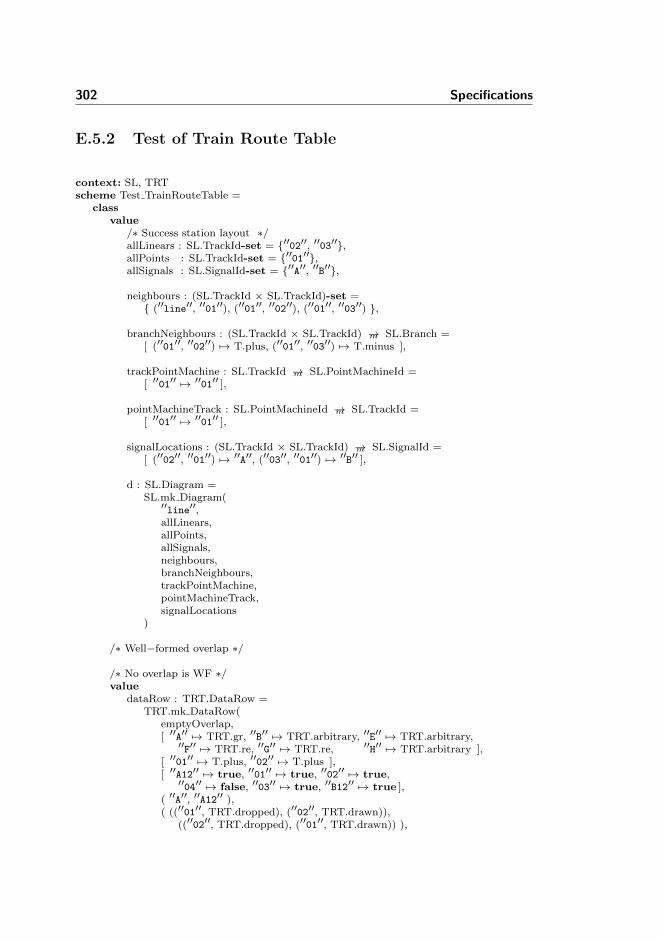
302 Specifications
E.5.2 Test of Train Route Table
context: SL, TRTscheme Test TrainRouteTable =
classvalue
/∗ Success station layout ∗/allLinears : SL.TrackId-set = {′′02′′, ′′03′′},allPoints : SL.TrackId-set = {′′01′′},allSignals : SL.SignalId-set = {′′A′′, ′′B′′},
neighbours : (SL.TrackId × SL.TrackId)-set ={ (′′line′′, ′′01′′), (′′01′′, ′′02′′), (′′01′′, ′′03′′) },
branchNeighbours : (SL.TrackId × SL.TrackId) →m SL.Branch =[ (′′01′′, ′′02′′) 7→ T.plus, (′′01′′, ′′03′′) 7→ T.minus ],
trackPointMachine : SL.TrackId →m SL.PointMachineId =[ ′′01′′ 7→ ′′01′′ ],
pointMachineTrack : SL.PointMachineId →m SL.TrackId =[ ′′01′′ 7→ ′′01′′ ],
signalLocations : (SL.TrackId × SL.TrackId) →m SL.SignalId =[ (′′02′′, ′′01′′) 7→ ′′A′′, (′′03′′, ′′01′′) 7→ ′′B′′ ],
d : SL.Diagram =SL.mk Diagram(
′′line′′,allLinears,allPoints,allSignals,neighbours,branchNeighbours,trackPointMachine,pointMachineTrack,signalLocations
)
/∗ Well−formed overlap ∗/
/∗ No overlap is WF ∗/value
dataRow : TRT.DataRow =TRT.mk DataRow(
emptyOverlap,[ ′′A′′ 7→ TRT.gr, ′′B′′ 7→ TRT.arbitrary, ′′E′′ 7→ TRT.arbitrary,
′′F′′ 7→ TRT.re, ′′G′′ 7→ TRT.re, ′′H′′ 7→ TRT.arbitrary ],[ ′′01′′ 7→ T.plus, ′′02′′ 7→ T.plus ],[ ′′A12′′ 7→ true, ′′01′′ 7→ true, ′′02′′ 7→ true,
′′04′′ 7→ false, ′′03′′ 7→ true, ′′B12′′ 7→ true ],( ′′A′′, ′′A12′′ ),( ((′′01′′, TRT.dropped), (′′02′′, TRT.drawn)),
((′′02′′, TRT.dropped), (′′01′′, TRT.drawn)) ),
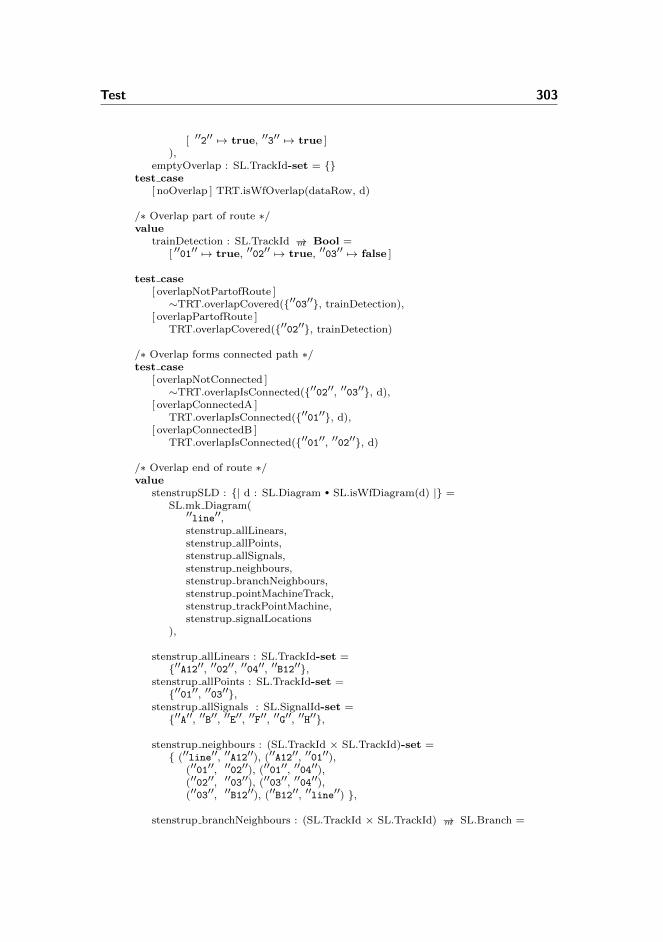
Test 303
[ ′′2′′ 7→ true, ′′3′′ 7→ true ]),
emptyOverlap : SL.TrackId-set = {}test case
[ noOverlap ] TRT.isWfOverlap(dataRow, d)
/∗ Overlap part of route ∗/value
trainDetection : SL.TrackId →m Bool =[ ′′01′′ 7→ true, ′′02′′ 7→ true, ′′03′′ 7→ false ]
test case[ overlapNotPartofRoute ]∼TRT.overlapCovered({′′03′′}, trainDetection),
[ overlapPartofRoute ]TRT.overlapCovered({′′02′′}, trainDetection)
/∗ Overlap forms connected path ∗/test case
[ overlapNotConnected ]∼TRT.overlapIsConnected({′′02′′, ′′03′′}, d),
[ overlapConnectedA ]TRT.overlapIsConnected({′′01′′}, d),
[ overlapConnectedB ]TRT.overlapIsConnected({′′01′′, ′′02′′}, d)
/∗ Overlap end of route ∗/value
stenstrupSLD : {| d : SL.Diagram • SL.isWfDiagram(d) |} =SL.mk Diagram(
′′line′′,stenstrup allLinears,stenstrup allPoints,stenstrup allSignals,stenstrup neighbours,stenstrup branchNeighbours,stenstrup pointMachineTrack,stenstrup trackPointMachine,stenstrup signalLocations
),
stenstrup allLinears : SL.TrackId-set ={′′A12′′, ′′02′′, ′′04′′, ′′B12′′},
stenstrup allPoints : SL.TrackId-set ={′′01′′, ′′03′′},
stenstrup allSignals : SL.SignalId-set ={′′A′′, ′′B′′, ′′E′′, ′′F′′, ′′G′′, ′′H′′},
stenstrup neighbours : (SL.TrackId × SL.TrackId)-set ={ (′′line′′, ′′A12′′), (′′A12′′, ′′01′′),
(′′01′′, ′′02′′), (′′01′′, ′′04′′),(′′02′′, ′′03′′), (′′03′′, ′′04′′),(′′03′′, ′′B12′′), (′′B12′′, ′′line′′) },
stenstrup branchNeighbours : (SL.TrackId × SL.TrackId) →m SL.Branch =

304 Specifications
[ (′′01′′, ′′02′′) 7→ T.plus,(′′01′′, ′′04′′) 7→ T.minus,(′′03′′, ′′02′′) 7→ T.plus,(′′03′′, ′′04′′) 7→ T.minus ],
stenstrup pointMachineTrack : SL.PointMachineId →m SL.TrackId =[ ′′01′′ 7→ ′′01′′,
′′02′′ 7→ ′′03′′ ],
stenstrup trackPointMachine : SL.TrackId →m SL.PointMachineId =[ ′′01′′ 7→ ′′01′′,
′′03′′ 7→ ′′02′′ ],
stenstrup signalLocations : (SL.TrackId × SL.TrackId) →m SL.SignalId =[ (′′line′′,′′A12′′) 7→ ′′A′′, (′′line′′,′′B12′′) 7→ ′′B′′,
(′′02′′, ′′01′′) 7→ ′′E′′, (′′04′′, ′′01′′) 7→ ′′F′′,(′′02′′, ′′03′′) 7→ ′′G′′, (′′04′′, ′′03′′) 7→ ′′H′′ ],
dataRow2 : TRT.DataRow =TRT.mk DataRow({′′03′′, ′′B12′′},[ ′′A′′ 7→ TRT.gr, ′′B′′ 7→ TRT.arbitrary, ′′E′′ 7→ TRT.arbitrary,
′′F′′ 7→ TRT.re, ′′G′′ 7→ TRT.re, ′′H′′ 7→ TRT.arbitrary ],[ ′′01′′ 7→ T.plus, ′′02′′ 7→ T.plus ],[ ′′A12′′ 7→ true, ′′01′′ 7→ true, ′′02′′ 7→ true,
′′04′′ 7→ false, ′′03′′ 7→ true, ′′B12′′ 7→ true ],( ′′A′′, ′′A12′′ ),( ((′′01′′, TRT.dropped), (′′02′′, TRT.drawn)),
((′′02′′, TRT.dropped), (′′01′′, TRT.drawn)) ),[ ′′2′′ 7→ true, ′′3′′ 7→ true ]
),
dataRow2D : TRT.DataRow =TRT.mk DataRow({′′02′′, ′′03′′},[ ′′A′′ 7→ TRT.gr, ′′B′′ 7→ TRT.arbitrary, ′′E′′ 7→ TRT.arbitrary,
′′F′′ 7→ TRT.re, ′′G′′ 7→ TRT.re, ′′H′′ 7→ TRT.arbitrary ],[ ′′01′′ 7→ T.plus, ′′02′′ 7→ T.plus ],[ ′′A12′′ 7→ true, ′′01′′ 7→ true, ′′02′′ 7→ true,
′′04′′ 7→ false, ′′03′′ 7→ true, ′′B12′′ 7→ true ],( ′′A′′, ′′A12′′ ),( ((′′01′′, TRT.dropped), (′′02′′, TRT.drawn)),
((′′02′′, TRT.dropped), (′′01′′, TRT.drawn)) ),[ ′′2′′ 7→ true, ′′3′′ 7→ true ]
)
test case[ overlapNotEOR ]∼TRT.endOfRoute(dataRow2D, stenstrupSLD),
[ overlapEOR ]TRT.endOfRoute(dataRow2, stenstrupSLD)
/∗ Well−formed signals ∗/value
signals1 : SL.SignalId →m TRT.Aspect =

Test 305
[ ′′A′′ 7→ TRT.re, ′′C′′ 7→ TRT.gr ],signals2 : SL.SignalId →m TRT.Aspect =
[ ′′A′′ 7→ TRT.gr, ′′B′′ 7→ TRT.re ]test case
[ nonExistingSignals ]∼TRT.existingSignals(signals1, d),
[ existingSignals ]TRT.existingSignals(signals2, d)
valueentrySignal : SL.SignalId = ′′A′′
test case[ stopEntry ]∼TRT.proceedEntry(entrySignal, signals1),
[ proceedEntry ]TRT.proceedEntry(entrySignal, signals2)
/∗ Well−formed points ∗/test case
[ nonexistingPointMachine ]∼TRT.pointMachinesExist({′′00′′}, d),
[ existingPointMachines ]TRT.pointMachinesExist({′′01′′}, d)
valuedataRow2B : TRT.DataRow =
TRT.mk DataRow({′′03′′, ′′B12′′},[ ′′A′′ 7→ TRT.gr, ′′B′′ 7→ TRT.arbitrary, ′′E′′ 7→ TRT.arbitrary,
′′F′′ 7→ TRT.re, ′′G′′ 7→ TRT.re, ′′H′′ 7→ TRT.arbitrary ],[ ],[ ′′A12′′ 7→ true, ′′01′′ 7→ true, ′′02′′ 7→ true,
′′04′′ 7→ false, ′′03′′ 7→ true, ′′B12′′ 7→ true ],( ′′A′′, ′′A12′′ ),( ((′′01′′, TRT.dropped), (′′02′′, TRT.drawn)),
((′′02′′, TRT.dropped), (′′01′′, TRT.drawn)) ),[ ′′2′′ 7→ true, ′′3′′ 7→ true ]
),
dataRow2C : TRT.DataRow =TRT.mk DataRow({′′03′′, ′′B12′′},[ ′′A′′ 7→ TRT.gr, ′′B′′ 7→ TRT.arbitrary, ′′E′′ 7→ TRT.arbitrary,
′′F′′ 7→ TRT.re, ′′G′′ 7→ TRT.re, ′′H′′ 7→ TRT.arbitrary ],[ ′′02′′ 7→ T.plus ],[ ′′A12′′ 7→ true, ′′01′′ 7→ true, ′′02′′ 7→ true,
′′04′′ 7→ false, ′′03′′ 7→ true, ′′B12′′ 7→ true ],( ′′A′′, ′′A12′′ ),( ((′′01′′, TRT.dropped), (′′02′′, TRT.drawn)),
((′′02′′, TRT.dropped), (′′01′′, TRT.drawn)) ),[ ′′2′′ 7→ true, ′′3′′ 7→ true ]
)
test case[ pointMachinesNotInTRT ]

306 Specifications
∼TRT.pointMachinesInTRT(dataRow2B, stenstrupSLD),[ pointMachineNotInTRT ]∼TRT.pointMachinesInTRT(dataRow2C, stenstrupSLD),
[ pointMachinesInTRT ]TRT.pointMachinesInTRT(dataRow2, stenstrupSLD)
valuedataRow10A : TRT.DataRow =
TRT.mk DataRow({},[ ′′A′′ 7→ TRT.arbitrary, ′′B′′ 7→ TRT.arbitrary, ′′E′′ 7→ TRT.arbitrary,
′′F′′ 7→ TRT.arbitrary, ′′G′′ 7→ TRT.re, ′′H′′ 7→ TRT.gr ],[ ′′01′′ 7→ T.arbitrary, ′′02′′ 7→ T.arbitrary ],[ ′′A12′′ 7→ false, ′′01′′ 7→ false, ′′02′′ 7→ false,
′′04′′ 7→ false, ′′03′′ 7→ true, ′′B12′′ 7→ true ],( ′′H′′, ′′03′′ ),( ((′′03′′, TRT.dropped), (′′B12′′, TRT.drawn)),
((′′B12′′, TRT.dropped), (′′03′′, TRT.drawn)) ),[ ′′2′′ 7→ true, ′′3′′ 7→ false, ′′5′′ 7→ true, ′′6′′ 7→ true,
′′7′′ 7→ false, ′′8′′ 7→ false, ′′9′′ 7→ true, ′′10′′ 7→ true ])
test case[ pointsInRouteLocked fail ]∼TRT.pointsInRouteLocked(dataRow10A, stenstrupSLD),
[ pointsInRouteLocked success ]TRT.pointsInRouteLocked(dataRow2, stenstrupSLD)
valuedataRow2A : TRT.DataRow =
TRT.mk DataRow({′′03′′, ′′B12′′},[ ′′A′′ 7→ TRT.gr, ′′B′′ 7→ TRT.arbitrary, ′′E′′ 7→ TRT.arbitrary,
′′F′′ 7→ TRT.re, ′′G′′ 7→ TRT.re, ′′H′′ 7→ TRT.arbitrary ],[ ′′01′′ 7→ T.plus, ′′02′′ 7→ T.minus ],[ ′′A12′′ 7→ true, ′′01′′ 7→ true, ′′02′′ 7→ true,
′′04′′ 7→ false, ′′03′′ 7→ true, ′′B12′′ 7→ true ],( ′′A′′, ′′A12′′ ),( ((′′01′′, TRT.dropped), (′′02′′, TRT.drawn)),
((′′02′′, TRT.dropped), (′′01′′, TRT.drawn)) ),[ ′′2′′ 7→ true, ′′3′′ 7→ true ]
)
test case[ pointsNotInCorrectPos ]∼TRT.correctPos(dataRow2A, stenstrupSLD),
[ pointsInCorrectPos ]TRT.correctPos(dataRow2, stenstrupSLD)
/∗ Well−formed train detection ∗/value
sections1 : SL.TrackId-set = {′′00′′, ′′01′′, ′′02′′},sections2 : SL.TrackId-set = {′′01′′, ′′02′′},sections3 : SL.TrackId-set = {′′01′′, ′′02′′, ′′03′′, ′′04′′},sections4 : SL.TrackId-set = {′′01′′, ′′02′′, ′′03′′}

Test 307
test case[ nonexistingTrackSections ]∼TRT.existingTrackSections(sections1, d),
[ tooFewTrackSections ]∼TRT.existingTrackSections(sections2, d),
[ tooManyTrackSections ]∼TRT.existingTrackSections(sections3, d),
[ existingTrackSections ]TRT.existingTrackSections(sections4, d)
valuetrainDetection1 : SL.TrackId →m Bool = [ ′′01′′ 7→ false ],trainDetection2 : SL.TrackId →m Bool = [ ′′01′′ 7→ true ]
test case[ emptyTrainDetection ]∼TRT.atLeastOneSectionInRoute([ ]),
[ noSectionInRoute ]∼TRT.atLeastOneSectionInRoute(trainDetection1),
[ atLeastOneSectionInRoute ]TRT.atLeastOneSectionInRoute(trainDetection2)
valuetrainDetection fail : SL.TrackId →m Bool =
[ ′′A12′′ 7→ true, ′′01′′ 7→ true, ′′02′′ 7→ false,′′04′′ 7→ false, ′′03′′ 7→ true, ′′B12′′ 7→ true ],
trainDetection succeed : SL.TrackId →m Bool =[ ′′A12′′ 7→ true, ′′01′′ 7→ true, ′′02′′ 7→ true,
′′04′′ 7→ false, ′′03′′ 7→ true, ′′B12′′ 7→ true ]
test case[ notConnectedRoute ]∼TRT.connectedRoute(trainDetection fail, stenstrupSLD),
[ connectedRoute ]TRT.connectedRoute(trainDetection succeed, stenstrupSLD)
valuetrainDetection fail2 : SL.TrackId →m Bool =
[ ′′A12′′ 7→ true, ′′01′′ 7→ true, ′′02′′ 7→ true,′′04′′ 7→ true, ′′03′′ 7→ true, ′′B12′′ 7→ true ]
test case[ justOneBranchNeighbour fail ]∼TRT.justOneBranchNeighbour(trainDetection fail2,
stenstrupSLD),[ justOneBranchNeighbour ]
TRT.justOneBranchNeighbour(trainDetection succeed,stenstrupSLD)
/∗ Well−formed signal release ∗/test case
[ nonexistingSignal ]∼TRT.isWfSignalRelease((′′C′′, ′′01′′), d),
[ existingSignal ]

308 Specifications
TRT.isWfSignalRelease((′′A′′,′′01′′), d)
test case[ nonexistingTrackSection ]∼TRT.isWfSignalRelease((′′A′′,′′00′′), d),
[ existingTrackSection ]TRT.isWfSignalRelease((′′A′′,′′01′′), d),
[ signalNotFollowedByTrackSection ]∼TRT.signalFollowedByTrackSection(′′A′′, ′′02′′, d),
[ signalFollowedByTrackSection ]TRT.signalFollowedByTrackSection(′′A′′, ′′01′′, d)
/∗ Well−formed train route release ∗/test case
[ notReverseTrackSections ]∼TRT.reverseTrackSections(′′01′′, ′′02′′, ′′01′′, ′′02′′),
[ reverseTrackSections ]TRT.reverseTrackSections(′′01′′, ′′02′′, ′′02′′, ′′01′′)
test case[ notReverseRelayState ]∼TRT.reverseRelayState(TRT.dropped, TRT.drawn,
TRT.drawn, TRT.dropped),[ reverseRelayState ]
TRT.reverseRelayState(TRT.dropped, TRT.drawn,TRT.dropped, TRT.drawn)
test case[ trackSectionNotPartOfRoute ]∼TRT.trackSectionPartOfRoute(′′00′′, dataRow),
[ trackSectionPartOfRoute ]TRT.trackSectionPartOfRoute(′′01′′, dataRow)
test case[ improperRelayState1 ]∼TRT.properRelayState(TRT.drawn, TRT.dropped),
[ improperRelayState2 ]∼TRT.properRelayState(TRT.drawn, TRT.drawn),
[ improperRelayState3 ]∼TRT.properRelayState(TRT.dropped, TRT.dropped),
[ properRelayState ]TRT.properRelayState(TRT.dropped, TRT.drawn)
/∗ Well−formed mutually blocking ∗/value
trt : TRT.TrainRouteTable =[ ′′1′′ 7→ dataRowA, ′′2′′ 7→ dataRowB ],
dataRowA : TRT.DataRow =TRT.mk DataRow({′′03′′, ′′B12′′},[ ′′A′′ 7→ TRT.gr, ′′B′′ 7→ TRT.arbitrary, ′′E′′ 7→ TRT.arbitrary,
′′F′′ 7→ TRT.re, ′′G′′ 7→ TRT.re, ′′H′′ 7→ TRT.arbitrary ],[ ′′01′′ 7→ T.plus, ′′02′′ 7→ T.plus ],
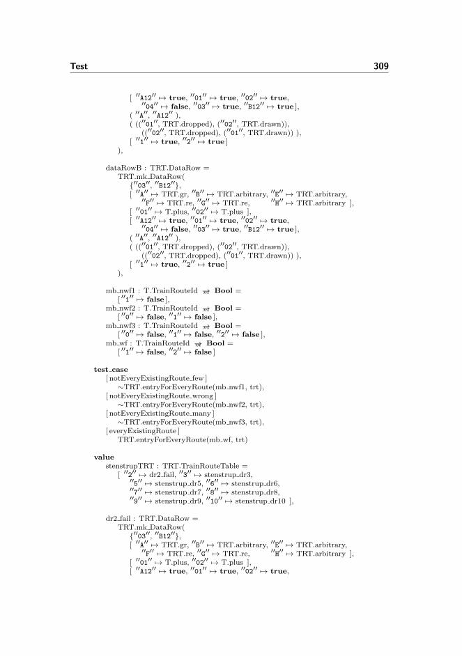
Test 309
[ ′′A12′′ 7→ true, ′′01′′ 7→ true, ′′02′′ 7→ true,′′04′′ 7→ false, ′′03′′ 7→ true, ′′B12′′ 7→ true ],
( ′′A′′, ′′A12′′ ),( ((′′01′′, TRT.dropped), (′′02′′, TRT.drawn)),
((′′02′′, TRT.dropped), (′′01′′, TRT.drawn)) ),[ ′′1′′ 7→ true, ′′2′′ 7→ true ]
),
dataRowB : TRT.DataRow =TRT.mk DataRow({′′03′′, ′′B12′′},[ ′′A′′ 7→ TRT.gr, ′′B′′ 7→ TRT.arbitrary, ′′E′′ 7→ TRT.arbitrary,
′′F′′ 7→ TRT.re, ′′G′′ 7→ TRT.re, ′′H′′ 7→ TRT.arbitrary ],[ ′′01′′ 7→ T.plus, ′′02′′ 7→ T.plus ],[ ′′A12′′ 7→ true, ′′01′′ 7→ true, ′′02′′ 7→ true,
′′04′′ 7→ false, ′′03′′ 7→ true, ′′B12′′ 7→ true ],( ′′A′′, ′′A12′′ ),( ((′′01′′, TRT.dropped), (′′02′′, TRT.drawn)),
((′′02′′, TRT.dropped), (′′01′′, TRT.drawn)) ),[ ′′1′′ 7→ true, ′′2′′ 7→ true ]
),
mb nwf1 : T.TrainRouteId →m Bool =[ ′′1′′ 7→ false ],
mb nwf2 : T.TrainRouteId →m Bool =[ ′′0′′ 7→ false, ′′1′′ 7→ false ],
mb nwf3 : T.TrainRouteId →m Bool =[ ′′0′′ 7→ false, ′′1′′ 7→ false, ′′2′′ 7→ false ],
mb wf : T.TrainRouteId →m Bool =[ ′′1′′ 7→ false, ′′2′′ 7→ false ]
test case[ notEveryExistingRoute few ]∼TRT.entryForEveryRoute(mb nwf1, trt),
[ notEveryExistingRoute wrong ]∼TRT.entryForEveryRoute(mb nwf2, trt),
[ notEveryExistingRoute many ]∼TRT.entryForEveryRoute(mb nwf3, trt),
[ everyExistingRoute ]TRT.entryForEveryRoute(mb wf, trt)
valuestenstrupTRT : TRT.TrainRouteTable =
[ ′′2′′ 7→ dr2 fail, ′′3′′ 7→ stenstrup dr3,′′5′′ 7→ stenstrup dr5, ′′6′′ 7→ stenstrup dr6,′′7′′ 7→ stenstrup dr7, ′′8′′ 7→ stenstrup dr8,′′9′′ 7→ stenstrup dr9, ′′10′′ 7→ stenstrup dr10 ],
dr2 fail : TRT.DataRow =TRT.mk DataRow({′′03′′, ′′B12′′},[ ′′A′′ 7→ TRT.gr, ′′B′′ 7→ TRT.arbitrary, ′′E′′ 7→ TRT.arbitrary,
′′F′′ 7→ TRT.re, ′′G′′ 7→ TRT.re, ′′H′′ 7→ TRT.arbitrary ],[ ′′01′′ 7→ T.plus, ′′02′′ 7→ T.plus ],[ ′′A12′′ 7→ true, ′′01′′ 7→ true, ′′02′′ 7→ true,

310 Specifications
′′04′′ 7→ false, ′′03′′ 7→ true, ′′B12′′ 7→ true ],( ′′A′′, ′′A12′′ ),( ((′′01′′, TRT.dropped), (′′02′′, TRT.drawn)),
((′′02′′, TRT.dropped), (′′01′′, TRT.drawn)) ),[ ′′2′′ 7→ false, ′′3′′ 7→ true, ′′5′′ 7→ true, ′′6′′ 7→ true,
′′7′′ 7→ true, ′′8′′ 7→ true, ′′9′′ 7→ false, ′′10′′ 7→ true ]),
stenstrup dr3 : TRT.DataRow =TRT.mk DataRow({′′03′′, ′′B12′′},[ ′′A′′ 7→ TRT.gr, ′′B′′ 7→ TRT.arbitrary, ′′E′′ 7→ TRT.re,
′′F′′ 7→ TRT.arbitrary, ′′G′′ 7→ TRT.arbitrary, ′′H′′ 7→ TRT.re ],[ ′′01′′ 7→ T.minus, ′′02′′ 7→ T.minus ],[ ′′A12′′ 7→ true, ′′01′′ 7→ true, ′′02′′ 7→ false,
′′04′′ 7→ true, ′′03′′ 7→ true, ′′B12′′ 7→ true ],( ′′A′′, ′′A12′′ ),( ((′′01′′, TRT.dropped), (′′04′′, TRT.drawn)),
((′′04′′, TRT.dropped), (′′01′′, TRT.drawn)) ),[ ′′2′′ 7→ true, ′′3′′ 7→ true, ′′5′′ 7→ true, ′′6′′ 7→ true,
′′7′′ 7→ true, ′′8′′ 7→ true, ′′9′′ 7→ true, ′′10′′ 7→ false ]),
stenstrup dr5 : TRT.DataRow =TRT.mk DataRow({′′A12′′, ′′01′′},[ ′′A′′ 7→ TRT.arbitrary, ′′B′′ 7→ TRT.gr, ′′E′′ 7→ TRT.re,
′′F′′ 7→ TRT.arbitrary, ′′G′′ 7→ TRT.arbitrary, ′′H′′ 7→ TRT.re ],[ ′′01′′ 7→ T.plus, ′′02′′ 7→ T.plus ],[ ′′A12′′ 7→ true, ′′01′′ 7→ true, ′′02′′ 7→ true,
′′04′′ 7→ false, ′′03′′ 7→ true, ′′B12′′ 7→ true ],( ′′B′′, ′′B12′′ ),( ((′′03′′, TRT.dropped), (′′02′′, TRT.drawn)),
((′′02′′, TRT.dropped), (′′03′′, TRT.drawn)) ),[ ′′2′′ 7→ true, ′′3′′ 7→ true, ′′5′′ 7→ true, ′′6′′ 7→ true,
′′7′′ 7→ false, ′′8′′ 7→ true, ′′9′′ 7→ true, ′′10′′ 7→ true ]),
stenstrup dr6 : TRT.DataRow =TRT.mk DataRow({′′A12′′, ′′01′′},[ ′′A′′ 7→ TRT.arbitrary, ′′B′′ 7→ TRT.gr, ′′E′′ 7→ TRT.arbitrary,
′′F′′ 7→ TRT.re, ′′G′′ 7→ TRT.re, ′′H′′ 7→ TRT.arbitrary ],[ ′′01′′ 7→ T.minus, ′′02′′ 7→ T.minus ],[ ′′A12′′ 7→ true, ′′01′′ 7→ true, ′′02′′ 7→ false,
′′04′′ 7→ true, ′′03′′ 7→ true, ′′B12′′ 7→ true ],( ′′B′′, ′′B12′′ ),( ((′′03′′, TRT.dropped), (′′04′′, TRT.drawn)),
((′′04′′, TRT.dropped), (′′03′′, TRT.drawn)) ),[ ′′2′′ 7→ true, ′′3′′ 7→ true, ′′5′′ 7→ true, ′′6′′ 7→ true,
′′7′′ 7→ true, ′′8′′ 7→ false, ′′9′′ 7→ true, ′′10′′ 7→ true ]),
stenstrup dr7 : TRT.DataRow =TRT.mk DataRow(

Test 311
{},[ ′′A′′ 7→ TRT.arbitrary, ′′B′′ 7→ TRT.arbitrary, ′′E′′ 7→ TRT.gr,
′′F′′ 7→ TRT.re, ′′G′′ 7→ TRT.arbitrary, ′′H′′ 7→ TRT.arbitrary ],[ ′′01′′ 7→ T.plus, ′′02′′ 7→ T.arbitrary ],[ ′′A12′′ 7→ true, ′′01′′ 7→ true, ′′02′′ 7→ false,
′′04′′ 7→ false, ′′03′′ 7→ false, ′′B12′′ 7→ false ],( ′′E′′, ′′01′′ ),( ((′′01′′, TRT.dropped), (′′A12′′, TRT.drawn)),
((′′A12′′, TRT.dropped), (′′01′′, TRT.drawn)) ),[ ′′2′′ 7→ true, ′′3′′ 7→ true, ′′5′′ 7→ false, ′′6′′ 7→ true,
′′7′′ 7→ true, ′′8′′ 7→ true, ′′9′′ 7→ false, ′′10′′ 7→ false ]),
stenstrup dr8 : TRT.DataRow =TRT.mk DataRow({},[ ′′A′′ 7→ TRT.arbitrary, ′′B′′ 7→ TRT.arbitrary, ′′E′′ 7→ TRT.re,
′′F′′ 7→ TRT.gr, ′′G′′ 7→ TRT.arbitrary, ′′H′′ 7→ TRT.arbitrary ],[ ′′01′′ 7→ T.minus, ′′02′′ 7→ T.arbitrary ],[ ′′A12′′ 7→ true, ′′01′′ 7→ true, ′′02′′ 7→ false,
′′04′′ 7→ false, ′′03′′ 7→ false, ′′B12′′ 7→ false ],( ′′F′′, ′′01′′ ),( ((′′01′′, TRT.dropped), (′′A12′′, TRT.drawn)),
((′′A12′′, TRT.dropped), (′′01′′, TRT.drawn)) ),[ ′′2′′ 7→ true, ′′3′′ 7→ true, ′′5′′ 7→ true, ′′6′′ 7→ false,
′′7′′ 7→ true, ′′8′′ 7→ true, ′′9′′ 7→ false, ′′10′′ 7→ false ]),
stenstrup dr9 : TRT.DataRow =TRT.mk DataRow({},[ ′′A′′ 7→ TRT.arbitrary, ′′B′′ 7→ TRT.arbitrary, ′′E′′ 7→ TRT.arbitrary,
′′F′′ 7→ TRT.arbitrary, ′′G′′ 7→ TRT.gr, ′′H′′ 7→ TRT.re ],[ ′′01′′ 7→ T.arbitrary, ′′02′′ 7→ T.plus ],[ ′′A12′′ 7→ false, ′′01′′ 7→ false, ′′02′′ 7→ false,
′′04′′ 7→ false, ′′03′′ 7→ true, ′′B12′′ 7→ true ],( ′′G′′, ′′03′′ ),( ((′′03′′, TRT.dropped), (′′B12′′, TRT.drawn)),
((′′B12′′, TRT.dropped), (′′03′′, TRT.drawn)) ),[ ′′2′′ 7→ false, ′′3′′ 7→ true, ′′5′′ 7→ true, ′′6′′ 7→ true,
′′7′′ 7→ false, ′′8′′ 7→ false, ′′9′′ 7→ true, ′′10′′ 7→ true ]),
stenstrup dr10 : TRT.DataRow =TRT.mk DataRow({},[ ′′A′′ 7→ TRT.arbitrary, ′′B′′ 7→ TRT.arbitrary, ′′E′′ 7→ TRT.arbitrary,
′′F′′ 7→ TRT.arbitrary, ′′G′′ 7→ TRT.re, ′′H′′ 7→ TRT.gr ],[ ′′01′′ 7→ T.arbitrary, ′′02′′ 7→ T.minus ],[ ′′A12′′ 7→ false, ′′01′′ 7→ false, ′′02′′ 7→ false,
′′04′′ 7→ false, ′′03′′ 7→ true, ′′B12′′ 7→ true ],( ′′H′′, ′′03′′ ),( ((′′03′′, TRT.dropped), (′′B12′′, TRT.drawn)),
((′′B12′′, TRT.dropped), (′′03′′, TRT.drawn)) ),[ ′′2′′ 7→ true, ′′3′′ 7→ false, ′′5′′ 7→ true, ′′6′′ 7→ true,

312 Specifications
′′7′′ 7→ false, ′′8′′ 7→ false, ′′9′′ 7→ true, ′′10′′ 7→ true ])
test case[ notconflictingIfShareSectionB ]∼TRT.conflictingWhenShareSection(′′2′′, stenstrupTRT),
[ conflictingIfShareSection ]TRT.conflictingWhenShareSection(′′3′′, stenstrupTRT)
valuestenstrupTRT2 : TRT.TrainRouteTable =
[ ′′2′′ 7→ dr2 fail2, ′′3′′ 7→ stenstrup dr3,′′5′′ 7→ stenstrup dr5, ′′6′′ 7→ stenstrup dr6,′′7′′ 7→ stenstrup dr7, ′′8′′ 7→ stenstrup dr8,′′9′′ 7→ stenstrup dr9, ′′10′′ 7→ stenstrup dr10 ],
dr2 fail2 : TRT.DataRow =TRT.mk DataRow({′′03′′, ′′B12′′},[ ′′A′′ 7→ TRT.gr, ′′B′′ 7→ TRT.arbitrary, ′′E′′ 7→ TRT.arbitrary,
′′F′′ 7→ TRT.re, ′′G′′ 7→ TRT.re, ′′H′′ 7→ TRT.arbitrary ],[ ′′01′′ 7→ T.plus, ′′02′′ 7→ T.plus ],[ ′′A12′′ 7→ true, ′′01′′ 7→ true, ′′02′′ 7→ true,
′′04′′ 7→ false, ′′03′′ 7→ true, ′′B12′′ 7→ true ],( ′′A′′, ′′A12′′ ),( ((′′01′′, TRT.dropped), (′′02′′, TRT.drawn)),
((′′02′′, TRT.dropped), (′′01′′, TRT.drawn)) ),[ ′′2′′ 7→ true, ′′3′′ 7→ true, ′′5′′ 7→ true, ′′6′′ 7→ true,
′′7′′ 7→ true, ′′8′′ 7→ true, ′′9′′ 7→ false, ′′10′′ 7→ false ])
test case- - Different pos, but not conflicting[ notConflictingWhenDifferentPos ]∼TRT.conflictingWhenDifferentPos(′′2′′, ′′10′′, stenstrupTRT2),
- - Same pos[ conflictingWhenDifferentPos samePos ]
TRT.conflictingWhenDifferentPos(′′2′′, ′′9′′, stenstrupTRT),- - Different pos and conflicting[ conflictingWhenDifferentPos ]
TRT.conflictingWhenDifferentPos(′′2′′, ′′10′′, stenstrupTRT)
end
E.5.3 Test of Transition System
context: T, TSscheme Test TransitionSystem =
classvalue
- - TS names
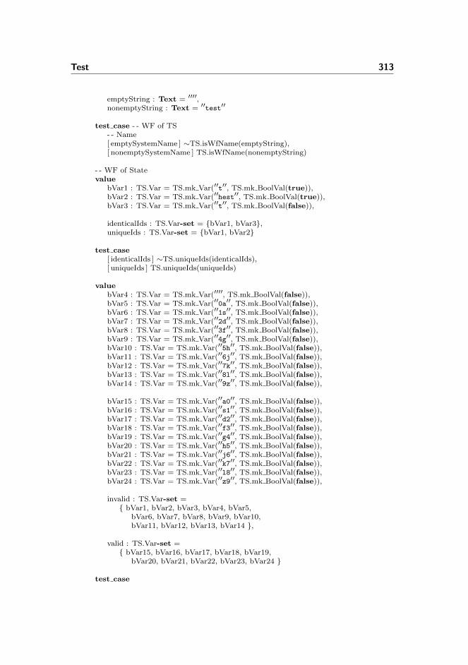
Test 313
emptyString : Text = ′′′′,nonemptyString : Text = ′′test′′
test case - - WF of TS- - Name[ emptySystemName ] ∼TS.isWfName(emptyString),[ nonemptySystemName ] TS.isWfName(nonemptyString)
- - WF of Statevalue
bVar1 : TS.Var = TS.mk Var(′′t′′, TS.mk BoolVal(true)),bVar2 : TS.Var = TS.mk Var(′′hest′′, TS.mk BoolVal(true)),bVar3 : TS.Var = TS.mk Var(′′t′′, TS.mk BoolVal(false)),
identicalIds : TS.Var-set = {bVar1, bVar3},uniqueIds : TS.Var-set = {bVar1, bVar2}
test case[ identicalIds ] ∼TS.uniqueIds(identicalIds),[ uniqueIds ] TS.uniqueIds(uniqueIds)
valuebVar4 : TS.Var = TS.mk Var(′′′′, TS.mk BoolVal(false)),bVar5 : TS.Var = TS.mk Var(′′0a′′, TS.mk BoolVal(false)),bVar6 : TS.Var = TS.mk Var(′′1s′′, TS.mk BoolVal(false)),bVar7 : TS.Var = TS.mk Var(′′2d′′, TS.mk BoolVal(false)),bVar8 : TS.Var = TS.mk Var(′′3f′′, TS.mk BoolVal(false)),bVar9 : TS.Var = TS.mk Var(′′4g′′, TS.mk BoolVal(false)),bVar10 : TS.Var = TS.mk Var(′′5h′′, TS.mk BoolVal(false)),bVar11 : TS.Var = TS.mk Var(′′6j′′, TS.mk BoolVal(false)),bVar12 : TS.Var = TS.mk Var(′′7k′′, TS.mk BoolVal(false)),bVar13 : TS.Var = TS.mk Var(′′8l′′, TS.mk BoolVal(false)),bVar14 : TS.Var = TS.mk Var(′′9z′′, TS.mk BoolVal(false)),
bVar15 : TS.Var = TS.mk Var(′′a0′′, TS.mk BoolVal(false)),bVar16 : TS.Var = TS.mk Var(′′s1′′, TS.mk BoolVal(false)),bVar17 : TS.Var = TS.mk Var(′′d2′′, TS.mk BoolVal(false)),bVar18 : TS.Var = TS.mk Var(′′f3′′, TS.mk BoolVal(false)),bVar19 : TS.Var = TS.mk Var(′′g4′′, TS.mk BoolVal(false)),bVar20 : TS.Var = TS.mk Var(′′h5′′, TS.mk BoolVal(false)),bVar21 : TS.Var = TS.mk Var(′′j6′′, TS.mk BoolVal(false)),bVar22 : TS.Var = TS.mk Var(′′k7′′, TS.mk BoolVal(false)),bVar23 : TS.Var = TS.mk Var(′′l8′′, TS.mk BoolVal(false)),bVar24 : TS.Var = TS.mk Var(′′z9′′, TS.mk BoolVal(false)),
invalid : TS.Var-set ={ bVar1, bVar2, bVar3, bVar4, bVar5,
bVar6, bVar7, bVar8, bVar9, bVar10,bVar11, bVar12, bVar13, bVar14 },
valid : TS.Var-set ={ bVar15, bVar16, bVar17, bVar18, bVar19,
bVar20, bVar21, bVar22, bVar23, bVar24 }
test case

314 Specifications
[ invalidIds ] ∼TS.validIds(invalid),[ validIds ] TS.validIds(valid)
- - WF of transitionsvalue
tinyBoolExp : T.BooleanExp = T.bool(true),
transition1 : TS.TransitionRule =TS.mk TransitionRule(emptyString, tinyBoolExp, {}),
transition2 : TS.TransitionRule =TS.mk TransitionRule(nonemptyString, tinyBoolExp, {})
test case[ emptyTransitionName ] ∼TS.validNames({transition1}),[ nonemptyTransitionName ] TS.validNames({transition2})
valuetinyBoolExp2 : T.BooleanExp = T.bool(false),transition3 : TS.TransitionRule =
TS.mk TransitionRule(nonemptyString, tinyBoolExp2, {}),transition4 : TS.TransitionRule =
TS.mk TransitionRule(′′TR4′′, tinyBoolExp2, {})
test case[ identicalTransitionNames ] ∼TS.uniqueNames({transition2, transition3}),[ uniqueTransitionNames ] TS.uniqueNames({transition3, transition4})
valuestate : TS.Var-set = {bVar1},boolExp : T.BooleanExp = T.literal(TS.id(bVar1)),tr : TS.TransitionRule =
TS.mk TransitionRule(′′notok′′, boolExp, {})
test case[ nonExistingIdsInGuard ] ∼TS.idsInGuardMustBeInState({}, {tr}),[ existingIdsInGuard ] TS.idsInGuardMustBeInState(state, {tr})
valueassignment : TS.Assignment =
TS.mk Assignment(TS.id(bVar1), T.BoolAssign(true)),assignments : TS.MultipleAssignment = {assignment},transition5 : TS.TransitionRule =
TS.mk TransitionRule(′′TR5′′, tinyBoolExp, assignments)test case
[ emptyAssignment ] ∼TS.nonemptyAssignment({transition2}),[ nonemptyAssignment ] TS.nonemptyAssignment({transition5})
valuestate1 : TS.Var-set = {bVar1},assignment1 : TS.Assignment =
TS.mk Assignment(TS.id(bVar2), T.BoolAssign(false)),transition1a : TS.TransitionRule =
TS.mk TransitionRule(′′TR1′′, tinyBoolExp, {assignment1}),transitions1 : TS.TransitionRule-set = {transition1a},assertions1 : TS.Assertion-set = {},

Test 315
ts1 : TS.TransitionSystem =TS.mk TransitionSystem(′′name′′, state1, transitions1, assertions1),
state2 : TS.Var-set = {bVar2},assignment2 : TS.Assignment =
TS.mk Assignment(TS.id(bVar2), T.BoolAssign(false)),transition2a : TS.TransitionRule =
TS.mk TransitionRule(′′TR1′′, tinyBoolExp, {assignment2}),transitions2 : TS.TransitionRule-set = {transition2a},assertions2 : TS.Assertion-set = {},ts2 : TS.TransitionSystem =
TS.mk TransitionSystem(′′name′′, state2, transitions2, assertions2)
test case[ assignToNonexistingIds ] ∼TS.assignmentToExistingIds(ts1),[ assignToExistingIds ] TS.assignmentToExistingIds(ts2)
valueassign1 : TS.Assignment =
TS.mk Assignment(TS.id(bVar1), T.BoolAssign(true)),assign2 : TS.Assignment =
TS.mk Assignment(TS.id(bVar2), T.BoolAssign(true)),assign3 : TS.Assignment =
TS.mk Assignment(TS.id(bVar1), T.BoolAssign(false)),
tr1 : TS.TransitionRule =TS.mk TransitionRule(′′TR1′′, tinyBoolExp, {assign1, assign2}),
tr2 : TS.TransitionRule =TS.mk TransitionRule(′′TR2′′, tinyBoolExp, {assign2, assign3}),
tr3 : TS.TransitionRule =TS.mk TransitionRule(′′TR3′′, tinyBoolExp, {assign1, assign3})
test case[ idUpdMoreThanOnce ] ∼TS.idUpdOnlyOnce({tr3}),[ idUpdOnlyOnce ] TS.idUpdOnlyOnce({tr1, tr2})
- - WF of assertionsvalue
tinyLTL : T.LTLformula = T.ltrl(TS.id(bVar1)),assert1 : TS.Assertion = (′′′′, tinyLTL),assert2 : TS.Assertion = (′′assertA′′, tinyLTL)
test case[ emptyAssertionName ] ∼TS.nonemptyNames({assert1}),[ nonemptyAssertionName ] TS.nonemptyNames({assert2})
valuetinyLTL2 : T.LTLformula = T.ltrl(TS.id(bVar2)),assert3 : TS.Assertion = (′′assertA′′, tinyLTL2),assert4 : TS.Assertion = (′′assertB′′, tinyLTL)
test case[ identicalAssertionNames ] ∼TS.uniqueNames({assert2, assert3}),[ uniqueAssertionNames ] TS.uniqueNames({assert2, assert4})
316 Specifications
test case[ nonexistingVars ] ∼TS.existingVars({bVar1}, {assert3}),[ existingVars ] TS.existingVars({bVar1}, {assert2})
end
E.5.4 Test of Object Relay Associations
context: ORA, SL, TRTscheme Test ObjectRelayAssociations =
class
valuestenstrupSLD : SL.Diagram =
SL.mk Diagram(′′line′′,allLinears,allPoints,allSignals,neighbours,branchNeighbours,pointMachineTrack,trackPointMachine,signalLocations
),
allLinears : SL.TrackId-set = {′′A12′′, ′′02′′, ′′04′′, ′′B12′′},allPoints : SL.TrackId-set = {′′01′′, ′′03′′},allSignals : SL.SignalId-set = {′′A′′, ′′B′′, ′′E′′, ′′F′′, ′′G′′, ′′H′′},
neighbours : (SL.TrackId × SL.TrackId)-set ={ (′′line′′, ′′A12′′), (′′A12′′, ′′01′′),
(′′01′′, ′′02′′), (′′01′′, ′′04′′),(′′02′′, ′′03′′), (′′03′′, ′′04′′),(′′03′′, ′′B12′′), (′′B12′′, ′′line′′) },
branchNeighbours : (SL.TrackId × SL.TrackId) →m SL.Branch =[ (′′01′′, ′′02′′) 7→ T.plus,
(′′01′′, ′′04′′) 7→ T.minus,(′′03′′, ′′02′′) 7→ T.plus,(′′03′′, ′′04′′) 7→ T.minus ],
pointMachineTrack : SL.PointMachineId →m SL.TrackId =[ ′′01′′ 7→ ′′01′′,
′′02′′ 7→ ′′03′′ ],
trackPointMachine : SL.TrackId →m SL.PointMachineId =[ ′′01′′ 7→ ′′01′′,
′′03′′ 7→ ′′02′′ ],
signalLocations : (SL.TrackId × SL.TrackId) →m SL.SignalId =

Test 317
[ (′′line′′, ′′A12′′) 7→ ′′A′′, (′′line′′, ′′B12′′) 7→ ′′B′′,(′′02′′, ′′01′′) 7→ ′′E′′, (′′04′′, ′′01′′) 7→ ′′F′′,(′′02′′, ′′03′′) 7→ ′′G′′, (′′04′′, ′′03′′) 7→ ′′H′′ ]
valuestenstrupTRT : TRT.TrainRouteTable =
[ ′′2′′ 7→ dataRow2, ′′3′′ 7→ dataRow3,′′5′′ 7→ dataRow5, ′′6′′ 7→ dataRow6,′′7′′ 7→ dataRow7, ′′8′′ 7→ dataRow8,′′9′′ 7→ dataRow9, ′′10′′ 7→ dataRow10 ],
dataRow2 : TRT.DataRow =TRT.mk DataRow({′′03′′, ′′B12′′},[ ′′A′′ 7→ TRT.gr, ′′B′′ 7→ TRT.arbitrary, ′′E′′ 7→ TRT.arbitrary,
′′F′′ 7→ TRT.re, ′′G′′ 7→ TRT.re, ′′H′′ 7→ TRT.arbitrary ],[ ′′01′′ 7→ T.plus, ′′02′′ 7→ T.plus ],[ ′′A12′′ 7→ true, ′′01′′ 7→ true, ′′02′′ 7→ true,
′′04′′ 7→ false, ′′03′′ 7→ true, ′′B12′′ 7→ true ],( ′′A′′, ′′A12′′ ),( ((′′01′′, TRT.dropped), (′′02′′, TRT.drawn)),
((′′02′′, TRT.dropped), (′′01′′, TRT.drawn)) ),[ ′′2′′ 7→ true, ′′3′′ 7→ true, ′′5′′ 7→ true, ′′6′′ 7→ true,
′′7′′ 7→ true, ′′8′′ 7→ true, ′′9′′ 7→ false, ′′10′′ 7→ true ]),
dataRow3 : TRT.DataRow =TRT.mk DataRow({′′03′′, ′′B12′′},[ ′′A′′ 7→ TRT.gr, ′′B′′ 7→ TRT.arbitrary, ′′E′′ 7→ TRT.re,
′′F′′ 7→ TRT.arbitrary, ′′G′′ 7→ TRT.arbitrary, ′′H′′ 7→ TRT.re ],[ ′′01′′ 7→ T.minus, ′′02′′ 7→ T.minus ],[ ′′A12′′ 7→ true, ′′01′′ 7→ true, ′′02′′ 7→ false,
′′04′′ 7→ true, ′′03′′ 7→ true, ′′B12′′ 7→ true ],( ′′A′′, ′′A12′′ ),( ((′′01′′, TRT.dropped), (′′04′′, TRT.drawn)),
((′′04′′, TRT.dropped), (′′01′′, TRT.drawn)) ),[ ′′2′′ 7→ true, ′′3′′ 7→ true, ′′5′′ 7→ true, ′′6′′ 7→ true,
′′7′′ 7→ true, ′′8′′ 7→ true, ′′9′′ 7→ true, ′′10′′ 7→ false ]),
dataRow5 : TRT.DataRow =TRT.mk DataRow({′′A12′′, ′′01′′},[ ′′A′′ 7→ TRT.arbitrary, ′′B′′ 7→ TRT.gr, ′′E′′ 7→ TRT.re,
′′F′′ 7→ TRT.arbitrary, ′′G′′ 7→ TRT.arbitrary, ′′H′′ 7→ TRT.re ],[ ′′01′′ 7→ T.plus, ′′02′′ 7→ T.plus ],[ ′′A12′′ 7→ true, ′′01′′ 7→ true, ′′02′′ 7→ true,
′′04′′ 7→ false, ′′03′′ 7→ true, ′′B12′′ 7→ true ],( ′′B′′, ′′B12′′ ),( ((′′03′′, TRT.dropped), (′′02′′, TRT.drawn)),
((′′02′′, TRT.dropped), (′′03′′, TRT.drawn)) ),[ ′′2′′ 7→ true, ′′3′′ 7→ true, ′′5′′ 7→ true, ′′6′′ 7→ true,
′′7′′ 7→ false, ′′8′′ 7→ true, ′′9′′ 7→ true, ′′10′′ 7→ true ]),

318 Specifications
dataRow6 : TRT.DataRow =TRT.mk DataRow({′′A12′′, ′′01′′},[ ′′A′′ 7→ TRT.arbitrary, ′′B′′ 7→ TRT.gr, ′′E′′ 7→ TRT.arbitrary,
′′F′′ 7→ TRT.re, ′′G′′ 7→ TRT.re, ′′H′′ 7→ TRT.arbitrary ],[ ′′01′′ 7→ T.minus, ′′02′′ 7→ T.minus ],[ ′′A12′′ 7→ true, ′′01′′ 7→ true, ′′02′′ 7→ false,
′′04′′ 7→ true, ′′03′′ 7→ true, ′′B12′′ 7→ true ],( ′′B′′, ′′B12′′ ),( ((′′03′′, TRT.dropped), (′′04′′, TRT.drawn)),
((′′04′′, TRT.dropped), (′′03′′, TRT.drawn)) ),[ ′′2′′ 7→ true, ′′3′′ 7→ true, ′′5′′ 7→ true, ′′6′′ 7→ true,
′′7′′ 7→ true, ′′8′′ 7→ false, ′′9′′ 7→ true, ′′10′′ 7→ true ]),
dataRow7 : TRT.DataRow =TRT.mk DataRow({},[ ′′A′′ 7→ TRT.arbitrary, ′′B′′ 7→ TRT.arbitrary, ′′E′′ 7→ TRT.gr,
′′F′′ 7→ TRT.re, ′′G′′ 7→ TRT.arbitrary, ′′H′′ 7→ TRT.arbitrary ],[ ′′01′′ 7→ T.plus, ′′02′′ 7→ T.arbitrary ],[ ′′A12′′ 7→ true, ′′01′′ 7→ true, ′′02′′ 7→ false,
′′04′′ 7→ false, ′′03′′ 7→ false, ′′B12′′ 7→ false ],( ′′E′′, ′′01′′ ),( ((′′01′′, TRT.dropped), (′′A12′′, TRT.drawn)),
((′′A12′′, TRT.dropped), (′′01′′, TRT.drawn)) ),[ ′′2′′ 7→ true, ′′3′′ 7→ true, ′′5′′ 7→ false, ′′6′′ 7→ true,
′′7′′ 7→ true, ′′8′′ 7→ true, ′′9′′ 7→ false, ′′10′′ 7→ false ]),
dataRow8 : TRT.DataRow =TRT.mk DataRow({},[ ′′A′′ 7→ TRT.arbitrary, ′′B′′ 7→ TRT.arbitrary, ′′E′′ 7→ TRT.re,
′′F′′ 7→ TRT.gr, ′′G′′ 7→ TRT.arbitrary, ′′H′′ 7→ TRT.arbitrary ],[ ′′01′′ 7→ T.minus, ′′02′′ 7→ T.arbitrary ],[ ′′A12′′ 7→ true, ′′01′′ 7→ true, ′′02′′ 7→ false,
′′04′′ 7→ false, ′′03′′ 7→ false, ′′B12′′ 7→ false ],( ′′F′′, ′′01′′ ),( ((′′01′′, TRT.dropped), (′′A12′′, TRT.drawn)),
((′′A12′′, TRT.dropped), (′′01′′, TRT.drawn)) ),[ ′′2′′ 7→ true, ′′3′′ 7→ true, ′′5′′ 7→ true, ′′6′′ 7→ false,
′′7′′ 7→ true, ′′8′′ 7→ true, ′′9′′ 7→ false, ′′10′′ 7→ false ]),
dataRow9 : TRT.DataRow =TRT.mk DataRow({},[ ′′A′′ 7→ TRT.arbitrary, ′′B′′ 7→ TRT.arbitrary, ′′E′′ 7→ TRT.arbitrary,
′′F′′ 7→ TRT.arbitrary, ′′G′′ 7→ TRT.gr, ′′H′′ 7→ TRT.re ],[ ′′01′′ 7→ T.arbitrary, ′′02′′ 7→ T.plus ],[ ′′A12′′ 7→ false, ′′01′′ 7→ false, ′′02′′ 7→ false,
′′04′′ 7→ false, ′′03′′ 7→ true, ′′B12′′ 7→ true ],( ′′G′′, ′′03′′ ),

Test 319
( ((′′03′′, TRT.dropped), (′′B12′′, TRT.drawn)),((′′B12′′, TRT.dropped), (′′03′′, TRT.drawn)) ),
[ ′′2′′ 7→ false, ′′3′′ 7→ true, ′′5′′ 7→ true, ′′6′′ 7→ true,′′7′′ 7→ false, ′′8′′ 7→ false, ′′9′′ 7→ true, ′′10′′ 7→ true ]
),
dataRow10 : TRT.DataRow =TRT.mk DataRow({},[ ′′A′′ 7→ TRT.arbitrary, ′′B′′ 7→ TRT.arbitrary, ′′E′′ 7→ TRT.arbitrary,
′′F′′ 7→ TRT.arbitrary, ′′G′′ 7→ TRT.re, ′′H′′ 7→ TRT.gr ],[ ′′01′′ 7→ T.arbitrary, ′′02′′ 7→ T.minus ],[ ′′A12′′ 7→ false, ′′01′′ 7→ false, ′′02′′ 7→ false,
′′04′′ 7→ false, ′′03′′ 7→ true, ′′B12′′ 7→ true ],( ′′H′′, ′′03′′ ),( ((′′03′′, TRT.dropped), (′′B12′′, TRT.drawn)),
((′′B12′′, TRT.dropped), (′′03′′, TRT.drawn)) ),[ ′′2′′ 7→ true, ′′3′′ 7→ false, ′′5′′ 7→ true, ′′6′′ 7→ true,
′′7′′ 7→ false, ′′8′′ 7→ false, ′′9′′ 7→ true, ′′10′′ 7→ true ]),
stenstrupAssocs : ORA.ObjectRelayAssociations =ORA.mk ObjectRelayAssociations(
routeRelayAssoc,trackRelayAssoc,pointRelayAssoc,signalRelayAssoc
),
routeRelayAssoc : T.TrainRouteId →m T.VarId =[ ′′2′′ 7→ ′′ia′′, ′′3′′ 7→ ′′ia′′,
′′5′′ 7→ ′′ib′′, ′′6′′ 7→ ′′ib′′,′′7′′ 7→ ′′ua′′, ′′8′′ 7→ ′′ua′′,′′9′′ 7→ ′′ub′′, ′′10′′ 7→ ′′ub′′ ],
trackRelayAssoc : SL.TrackId →m T.VarId =[ ′′A12′′ 7→ ′′a12′′, ′′01′′ 7→ ′′t01′′, ′′02′′ 7→ ′′t02′′,
′′B12′′ 7→ ′′b12′′, ′′03′′ 7→ ′′t03′′, ′′04′′ 7→ ′′t04′′ ],
pointRelayAssoc : SL.PointMachineId ×SL.Branch →m T.VarId =[ (′′01′′, T.plus) 7→ ′′plus01′′, (′′01′′, T.minus) 7→ ′′minus01′′,
(′′02′′, T.plus) 7→ ′′plus02′′, (′′02′′, T.minus) 7→ ′′minus02′′ ],
signalRelayAssoc : SL.SignalId × ORA.Lamp →m T.VarId =[ (′′A′′, ORA.gr) 7→ ′′aGreen′′, (′′A′′, ORA.re) 7→ ′′aRed′′,
(′′B′′, ORA.gr) 7→ ′′bGreen′′, (′′B′′, ORA.re) 7→ ′′bRed′′,(′′E′′, ORA.gr) 7→ ′′eGreen′′, (′′E′′, ORA.re) 7→ ′′eRed′′,(′′F′′, ORA.gr) 7→ ′′fGreen′′, (′′F′′, ORA.re) 7→ ′′fRed′′,(′′G′′, ORA.gr) 7→ ′′gGreen′′, (′′G′′, ORA.re) 7→ ′′gRed′′,(′′H′′, ORA.gr) 7→ ′′hGreen′′, (′′H′′, ORA.re) 7→ ′′hRed′′ ]
/∗ Well−fomnedness of ORA ∗/value
assocs fail0A : ORA.ObjectRelayAssociations =

320 Specifications
ORA.mk ObjectRelayAssociations(routeRelayAssoc fail0,trackRelayAssoc fail0,pointRelayAssoc,signalRelayAssoc
),
assocs fail0B : ORA.ObjectRelayAssociations =ORA.mk ObjectRelayAssociations(
routeRelayAssoc fail0,trackRelayAssoc,pointRelayAssoc fail0,signalRelayAssoc
),
assocs fail0C : ORA.ObjectRelayAssociations =ORA.mk ObjectRelayAssociations(
routeRelayAssoc fail0,trackRelayAssoc,pointRelayAssoc,signalRelayAssoc fail0
),
assocs fail0D : ORA.ObjectRelayAssociations =ORA.mk ObjectRelayAssociations(
routeRelayAssoc fail0,trackRelayAssoc fail0,pointRelayAssoc fail0,signalRelayAssoc
),
assocs fail0E : ORA.ObjectRelayAssociations =ORA.mk ObjectRelayAssociations(
routeRelayAssoc fail0,trackRelayAssoc fail0,pointRelayAssoc,signalRelayAssoc fail0
),
assocs fail0F : ORA.ObjectRelayAssociations =ORA.mk ObjectRelayAssociations(
routeRelayAssoc,trackRelayAssoc fail0,pointRelayAssoc fail0,signalRelayAssoc fail0
),
assocs fail0G : ORA.ObjectRelayAssociations =ORA.mk ObjectRelayAssociations(
routeRelayAssoc,trackRelayAssoc fail0,pointRelayAssoc,signalRelayAssoc fail0
),

Test 321
assocs fail0H : ORA.ObjectRelayAssociations =ORA.mk ObjectRelayAssociations(
routeRelayAssoc,trackRelayAssoc fail0,pointRelayAssoc fail0,signalRelayAssoc fail0
),
routeRelayAssoc fail0 : T.TrainRouteId →m T.VarId =[ ′′2′′ 7→ ′′ia′′, ′′3′′ 7→ ′′fail′′,
′′5′′ 7→ ′′ib′′, ′′6′′ 7→ ′′ib′′,′′7′′ 7→ ′′ua′′, ′′8′′ 7→ ′′ua′′,′′9′′ 7→ ′′ub′′, ′′10′′ 7→ ′′ub′′ ],
trackRelayAssoc fail0 : SL.TrackId →m T.VarId =[ ′′A12′′ 7→ ′′a12′′, ′′01′′ 7→ ′′t01′′, ′′02′′ 7→ ′′t02′′,
′′B12′′ 7→ ′′b12′′, ′′03′′ 7→ ′′t03′′, ′′04′′ 7→ ′′fail′′ ],
pointRelayAssoc fail0 : SL.PointMachineId ×SL.Branch →m T.VarId =[ (′′01′′, T.plus) 7→ ′′plus01′′, (′′01′′, T.minus) 7→ ′′minus01′′,
(′′02′′, T.plus) 7→ ′′fail′′, (′′02′′, T.minus) 7→ ′′minus02′′ ],
signalRelayAssoc fail0 : SL.SignalId × ORA.Lamp →m T.VarId =[ (′′A′′, ORA.gr) 7→ ′′aGreen′′, (′′A′′, ORA.re) 7→ ′′aRed′′,
(′′B′′, ORA.gr) 7→ ′′bGreen′′, (′′B′′, ORA.re) 7→ ′′bRed′′,(′′E′′, ORA.gr) 7→ ′′eGreen′′, (′′E′′, ORA.re) 7→ ′′fail′′,(′′F′′, ORA.gr) 7→ ′′fGreen′′, (′′F′′, ORA.re) 7→ ′′fRed′′,(′′G′′, ORA.gr) 7→ ′′gGreen′′, (′′G′′, ORA.re) 7→ ′′gRed′′,(′′H′′, ORA.gr) 7→ ′′hGreen′′, (′′H′′, ORA.re) 7→ ′′hRed′′ ]
test case[ noRelayVariableOverlap failA ]∼ORA.noRelayVariableOverlap(assocs fail0A),
[ noRelayVariableOverlap failB ]∼ORA.noRelayVariableOverlap(assocs fail0B),
[ noRelayVariableOverlap failC ]∼ORA.noRelayVariableOverlap(assocs fail0C),
[ noRelayVariableOverlap failD ]∼ORA.noRelayVariableOverlap(assocs fail0D),
[ noRelayVariableOverlap failE ]∼ORA.noRelayVariableOverlap(assocs fail0E),
[ noRelayVariableOverlap failF ]∼ORA.noRelayVariableOverlap(assocs fail0F),
[ noRelayVariableOverlap failG ]∼ORA.noRelayVariableOverlap(assocs fail0G),
[ noRelayVariableOverlap failH ]∼ORA.noRelayVariableOverlap(assocs fail0H),
[ noRelayVariableOverlap ok ]ORA.noRelayVariableOverlap(stenstrupAssocs)
/∗ Well−formedness of route associations ∗/value
assocs fail1 : ORA.ObjectRelayAssociations =ORA.mk ObjectRelayAssociations(
322 Specifications
routeRelayAssoc fail,trackRelayAssoc,pointRelayAssoc,signalRelayAssoc
),
routeRelayAssoc fail : T.TrainRouteId →m T.VarId =[ ′′1′′ 7→ ′′ia′′, ′′2′′ 7→ ′′ia′′,
′′3′′ 7→ ′′ib′′, ′′4′′ 7→ ′′ib′′,′′5′′ 7→ ′′ua′′, ′′6′′ 7→ ′′ua′′,′′7′′ 7→ ′′ub′′, ′′8′′ 7→ ′′ub′′ ]
test case[ routeAssoc fail ] ∼ORA.isWfRouteAssoc(stenstrupTRT, assocs fail1),[ routeAssoc ok ] ORA.isWfRouteAssoc(stenstrupTRT, stenstrupAssocs)
/∗ Well−formedness of track associations ∗/value
assocs fail2 : ORA.ObjectRelayAssociations =ORA.mk ObjectRelayAssociations(
routeRelayAssoc,trackRelayAssoc fail,pointRelayAssoc,signalRelayAssoc
),
trackRelayAssoc fail : SL.TrackId →m T.VarId =[ ′′A12′′ 7→ ′′a12′′, ′′t01′′ 7→ ′′t01′′, ′′t02′′ 7→ ′′t02′′,
′′B12′′ 7→ ′′b12′′, ′′t03′′ 7→ ′′t03′′, ′′t04′′ 7→ ′′t04′′ ]
test case[ trackAssoc fail ] ∼ORA.isWfTrackAssoc(stenstrupSLD, assocs fail2),[ trackAssoc ok ] ORA.isWfTrackAssoc(stenstrupSLD, stenstrupAssocs)
/∗ Well−formedness of point associations ∗/value
assocs fail3 : ORA.ObjectRelayAssociations =ORA.mk ObjectRelayAssociations(
routeRelayAssoc,trackRelayAssoc,pointRelayAssoc fail1,signalRelayAssoc
),
pointRelayAssoc fail1 : SL.PointMachineId ×SL.Branch →m T.VarId =[ (′′01′′, T.plus) 7→ ′′plus01′′, (′′02′′, T.minus) 7→ ′′minus01′′,
(′′03′′, T.plus) 7→ ′′plus02′′, (′′04′′, T.minus) 7→ ′′minus02′′ ],
assocs fail4 : ORA.ObjectRelayAssociations =ORA.mk ObjectRelayAssociations(
routeRelayAssoc,trackRelayAssoc,pointRelayAssoc fail2,signalRelayAssoc
Test 323
),
pointRelayAssoc fail2 : SL.PointMachineId ×SL.Branch →m T.VarId =[ (′′01′′, T.plus) 7→ ′′plus01′′, (′′01′′, T.minus) 7→ ′′plus01′′,
(′′02′′, T.plus) 7→ ′′plus02′′, (′′02′′, T.minus) 7→ ′′minus02′′ ],
assocs fail5 : ORA.ObjectRelayAssociations =ORA.mk ObjectRelayAssociations(
routeRelayAssoc,trackRelayAssoc,pointRelayAssoc fail3,signalRelayAssoc
),
pointRelayAssoc fail3 : SL.PointMachineId ×SL.Branch →m T.VarId =[ (′′01′′, T.plus) 7→ ′′plus01′′, (′′01′′, T.minus) 7→ ′′minus01′′,
(′′02′′, T.plus) 7→ ′′plus01′′, (′′02′′, T.minus) 7→ ′′minus02′′ ]
test case[ pointAssoc existing fail ]∼ORA.existingPointMachines(stenstrupSLD, assocs fail3),
[ pointAssoc different fail1 ]∼ORA.differentPointRelays(assocs fail4),
[ pointAssoc different fail2 ]∼ORA.differentPointRelays(assocs fail5),
[ pointAssoc ok ]ORA.isWfPointAssoc(stenstrupSLD, stenstrupAssocs)
/∗ Well−formedness of signal associations ∗/value
assocs fail6 : ORA.ObjectRelayAssociations =ORA.mk ObjectRelayAssociations(
routeRelayAssoc,trackRelayAssoc,pointRelayAssoc,signalRelayAssoc fail1
),
signalRelayAssoc fail1 : SL.SignalId × ORA.Lamp →m T.VarId =[ (′′A′′, ORA.gr) 7→ ′′aGreen′′, (′′A′′, ORA.re) 7→ ′′aRed′′,
(′′B′′, ORA.gr) 7→ ′′bGreen′′, (′′B′′, ORA.re) 7→ ′′bRed′′,(′′C′′, ORA.gr) 7→ ′′eGreen′′, (′′C′′, ORA.re) 7→ ′′eRed′′,(′′F′′, ORA.gr) 7→ ′′fGreen′′, (′′F′′, ORA.re) 7→ ′′fRed′′,(′′G′′, ORA.gr) 7→ ′′gGreen′′, (′′G′′, ORA.re) 7→ ′′gRed′′,(′′H′′, ORA.gr) 7→ ′′hGreen′′, (′′H′′, ORA.re) 7→ ′′hRed′′ ],
assocs fail7 : ORA.ObjectRelayAssociations =ORA.mk ObjectRelayAssociations(
routeRelayAssoc,trackRelayAssoc,pointRelayAssoc,signalRelayAssoc fail2
),
324 Specifications
signalRelayAssoc fail2 : SL.SignalId × ORA.Lamp →m T.VarId =[ (′′A′′, ORA.gr) 7→ ′′aGreen′′, (′′A′′, ORA.re) 7→ ′′aGreen′′,
(′′B′′, ORA.gr) 7→ ′′bGreen′′, (′′B′′, ORA.re) 7→ ′′bRed′′,(′′E′′, ORA.gr) 7→ ′′eGreen′′, (′′E′′, ORA.re) 7→ ′′eRed′′,(′′F′′, ORA.gr) 7→ ′′fGreen′′, (′′F′′, ORA.re) 7→ ′′fRed′′,(′′G′′, ORA.gr) 7→ ′′gGreen′′, (′′G′′, ORA.re) 7→ ′′gRed′′,(′′H′′, ORA.gr) 7→ ′′hGreen′′, (′′H′′, ORA.re) 7→ ′′hRed′′ ]
test case[ signalAssoc existing fail ]∼ORA.existingSignals(stenstrupSLD, assocs fail6),
[ signalAssoc different fail ]∼ORA.differentLampRelays(assocs fail7),
[ signalAssoc ok ]ORA.isWfSignalAssoc(stenstrupSLD, stenstrupAssocs)
end
E.5.5 Test of Train Movement Associations
context: TMA, SLscheme Test TrainMovementAssociations =
class
valuestenstrupSLD : SL.Diagram =
SL.mk Diagram(′′line′′,allLinears,allPoints,allSignals,neighbours,branchNeighbours,pointMachineTrack,trackPointMachine,signalLocations
),
allLinears : SL.TrackId-set = {′′A12′′, ′′02′′, ′′04′′, ′′B12′′},allPoints : SL.TrackId-set = {′′01′′, ′′03′′},allSignals : SL.SignalId-set = {′′A′′, ′′B′′, ′′E′′, ′′F′′, ′′G′′, ′′H′′},
neighbours : (SL.TrackId × SL.TrackId)-set ={ (′′line′′, ′′A12′′), (′′A12′′, ′′01′′),
(′′01′′, ′′02′′), (′′01′′, ′′04′′),(′′02′′, ′′03′′), (′′03′′, ′′04′′),(′′03′′, ′′B12′′), (′′B12′′, ′′line′′) },
branchNeighbours : (SL.TrackId × SL.TrackId) →m SL.Branch =[ (′′01′′, ′′02′′) 7→ T.plus,

Test 325
(′′01′′, ′′04′′) 7→ T.minus,(′′03′′, ′′02′′) 7→ T.plus,(′′03′′, ′′04′′) 7→ T.minus ],
pointMachineTrack : SL.PointMachineId →m SL.TrackId =[ ′′01′′ 7→ ′′01′′,
′′02′′ 7→ ′′03′′ ],
trackPointMachine : SL.TrackId →m SL.PointMachineId =[ ′′01′′ 7→ ′′01′′,
′′03′′ 7→ ′′02′′ ],
signalLocations : (SL.TrackId × SL.TrackId) →m SL.SignalId =[ (′′line′′, ′′A12′′) 7→ ′′A′′, (′′line′′, ′′B12′′) 7→ ′′B′′,
(′′02′′, ′′01′′) 7→ ′′E′′, (′′04′′, ′′01′′) 7→ ′′F′′,(′′02′′, ′′03′′) 7→ ′′G′′, (′′04′′, ′′03′′) 7→ ′′H′′ ],
stenstrupTMA : TMA.TrainMovementAssociations =TMA.mk TrainMovementAssociations(
connectionVars,counterVars,directionFwdVars,directionBwdVars,directions
),
connectionVars : (SL.TrackId × SL.TrackId) →m T.VarId =[ (′′A12′′, ′′01′′) 7→ ′′con_A12_01′′,
(′′01′′, ′′02′′) 7→ ′′con_01_02′′,(′′01′′, ′′04′′) 7→ ′′con_01_04′′,(′′02′′, ′′03′′) 7→ ′′con_02_03′′,(′′03′′, ′′04′′) 7→ ′′con_03_04′′,(′′03′′, ′′B12′′) 7→ ′′con_03_B12′′
],
counterVars : SL.TrackId →m T.VarId =[ ′′A12′′ 7→ ′′cnt_A12′′, ′′B12′′ 7→ ′′cnt_B12′′,
′′01′′ 7→ ′′cnt_01′′, ′′02′′ 7→ ′′cnt_02′′,′′03′′ 7→ ′′cnt_03′′, ′′04′′ 7→ ′′cnt_04′′
],
directionFwdVars : SL.TrackId →m T.VarId =[ ′′A12′′ 7→ ′′fwd_A12′′, ′′B12′′ 7→ ′′fwd_B12′′,
′′01′′ 7→ ′′fwd_01′′, ′′02′′ 7→ ′′fwd_02′′,′′03′′ 7→ ′′fwd_03′′, ′′04′′ 7→ ′′fwd_04′′
],
directionBwdVars : SL.TrackId →m T.VarId =[ ′′A12′′ 7→ ′′bwd_A12′′, ′′B12′′ 7→ ′′bwd_B12′′,
′′01′′ 7→ ′′bwd_01′′, ′′02′′ 7→ ′′bwd_02′′,′′03′′ 7→ ′′bwd_03′′, ′′04′′ 7→ ′′bwd_04′′
],
directions : (SL.TrackId × SL.TrackId) →m T.Direction =[ (′′line′′, ′′A12′′) 7→ T.fwd, (′′A12′′, ′′line′′) 7→ T.bwd,

326 Specifications
(′′A12′′, ′′01′′) 7→ T.fwd, (′′01′′, ′′A12′′) 7→ T.bwd,(′′01′′, ′′02′′) 7→ T.fwd, (′′02′′, ′′01′′) 7→ T.bwd,(′′01′′, ′′04′′) 7→ T.fwd, (′′04′′, ′′01′′) 7→ T.bwd,(′′02′′, ′′03′′) 7→ T.fwd, (′′03′′, ′′02′′) 7→ T.bwd,(′′03′′, ′′04′′) 7→ T.fwd, (′′04′′, ′′03′′) 7→ T.bwd,(′′03′′, ′′B12′′) 7→ T.fwd, (′′B12′′, ′′03′′) 7→ T.bwd,(′′B12′′, ′′line′′) 7→ T.fwd, (′′line′′, ′′B12′′) 7→ T.bwd ]
valuetma fail0A : TMA.TrainMovementAssociations =
TMA.mk TrainMovementAssociations(connectionVars fail0,counterVars fail0,directionFwdVars,directionBwdVars,directions
),
tma fail0B : TMA.TrainMovementAssociations =TMA.mk TrainMovementAssociations(
connectionVars fail0,counterVars,directionFwdVars,directionBwdVars fail0,directions
),
tma fail0C : TMA.TrainMovementAssociations =TMA.mk TrainMovementAssociations(
connectionVars,counterVars fail0,directionFwdVars fail0,directionBwdVars,directions
),
tma fail0D : TMA.TrainMovementAssociations =TMA.mk TrainMovementAssociations(
connectionVars,counterVars fail0,directionFwdVars,directionBwdVars fail0,directions
),
tma fail0E : TMA.TrainMovementAssociations =TMA.mk TrainMovementAssociations(
connectionVars,counterVars,directionFwdVars fail0,directionBwdVars fail0,directions
),
tma fail0F : TMA.TrainMovementAssociations =
Test 327
TMA.mk TrainMovementAssociations(connectionVars fail0,counterVars fail0,directionFwdVars fail0,directionBwdVars,directions
),
tma fail0G : TMA.TrainMovementAssociations =TMA.mk TrainMovementAssociations(
connectionVars fail0,counterVars fail0,directionFwdVars,directionBwdVars fail0,directions
),
tma fail0H : TMA.TrainMovementAssociations =TMA.mk TrainMovementAssociations(
connectionVars fail0,counterVars,directionFwdVars fail0,directionBwdVars fail0,directions
),
tma fail0I : TMA.TrainMovementAssociations =TMA.mk TrainMovementAssociations(
connectionVars,counterVars fail0,directionFwdVars fail0,directionBwdVars fail0,directions
),
connectionVars fail0 : (SL.TrackId × SL.TrackId) →m T.VarId =[ (′′A12′′, ′′01′′) 7→ ′′fail′′,
(′′01′′, ′′02′′) 7→ ′′con_01_02′′,(′′01′′, ′′04′′) 7→ ′′con_01_04′′,(′′02′′, ′′03′′) 7→ ′′con_02_03′′,(′′03′′, ′′04′′) 7→ ′′con_03_04′′,(′′03′′, ′′B12′′) 7→ ′′con_03_B12′′
],
counterVars fail0 : SL.TrackId →m T.VarId =[ ′′A12′′ 7→ ′′cnt_A12′′, ′′B12′′ 7→ ′′fail′′,
′′01′′ 7→ ′′cnt_01′′, ′′02′′ 7→ ′′cnt_02′′,′′03′′ 7→ ′′cnt_03′′, ′′04′′ 7→ ′′cnt_04′′
],
directionFwdVars fail0 : SL.TrackId →m T.VarId =[ ′′A12′′ 7→ ′′fwd_A12′′, ′′B12′′ 7→ ′′fwd_B12′′,
′′01′′ 7→ ′′fail′′, ′′02′′ 7→ ′′fwd_02′′,′′03′′ 7→ ′′fwd_03′′, ′′04′′ 7→ ′′fwd_04′′
],
328 Specifications
directionBwdVars fail0 : SL.TrackId →m T.VarId =[ ′′A12′′ 7→ ′′bwd_A12′′, ′′B12′′ 7→ ′′bwd_B12′′,
′′01′′ 7→ ′′bwd_01′′, ′′02′′ 7→ ′′bwd_02′′,′′03′′ 7→ ′′bwd_03′′, ′′04′′ 7→ ′′fail′′
]
test case[ noRelayVariableOverlap failA ]∼TMA.noRelayVariableOverlap(tma fail0A),
[ noRelayVariableOverlap failB ]∼TMA.noRelayVariableOverlap(tma fail0B),
[ noRelayVariableOverlap failC ]∼TMA.noRelayVariableOverlap(tma fail0C),
[ noRelayVariableOverlap failD ]∼TMA.noRelayVariableOverlap(tma fail0D),
[ noRelayVariableOverlap failE ]∼TMA.noRelayVariableOverlap(tma fail0E),
[ noRelayVariableOverlap failF ]∼TMA.noRelayVariableOverlap(tma fail0F),
[ noRelayVariableOverlap failG ]∼TMA.noRelayVariableOverlap(tma fail0G),
[ noRelayVariableOverlap failH ]∼TMA.noRelayVariableOverlap(tma fail0H),
[ noRelayVariableOverlap failI ]∼TMA.noRelayVariableOverlap(tma fail0I),
[ noRelayVariableOverlap ok ]TMA.noRelayVariableOverlap(stenstrupTMA)
/∗ Connection Vars ∗/value
tma fail1 : TMA.TrainMovementAssociations =TMA.mk TrainMovementAssociations(
connectionVars fail1A,counterVars,directionFwdVars,directionBwdVars,directions
),
connectionVars fail1A : (SL.TrackId × SL.TrackId) →m T.VarId =[ (′′A12′′, ′′B12′′) 7→ ′′con_A12_01′′,
(′′01′′, ′′02′′) 7→ ′′con_01_02′′,(′′01′′, ′′04′′) 7→ ′′con_01_04′′,(′′02′′, ′′03′′) 7→ ′′con_02_03′′,(′′03′′, ′′04′′) 7→ ′′con_03_04′′,(′′03′′, ′′B12′′) 7→ ′′con_03_B12′′
],
connectionVars fail1B : (SL.TrackId × SL.TrackId) →m T.VarId =[ (′′A12′′, ′′01′′) 7→ ′′con_A12_01′′,
(′′01′′, ′′02′′) 7→ ′′same′′,(′′01′′, ′′04′′) 7→ ′′con_01_04′′,(′′02′′, ′′03′′) 7→ ′′con_02_03′′,(′′03′′, ′′04′′) 7→ ′′same′′,
Test 329
(′′03′′, ′′B12′′) 7→ ′′con_03_B12′′
]
test case[ conVarsValidDomain fail ]∼TMA.conVarsValidDomain(stenstrupSLD, tma fail1),
[ conVarsValidRange fail ]∼TMA.conVarsValidRange(connectionVars fail1B),
[ connectionVars ]TMA.isWfConnectionVars(stenstrupSLD, stenstrupTMA)
/∗ Counter Vars ∗/value
tma fail2 : TMA.TrainMovementAssociations =TMA.mk TrainMovementAssociations(
connectionVars,counterVars fail2A,directionFwdVars,directionBwdVars,directions
),
counterVars fail2A : SL.TrackId →m T.VarId =[ ′′A12′′ 7→ ′′cnt_A12′′, ′′B12′′ 7→ ′′cnt_B12′′,
′′01′′ 7→ ′′cnt_01′′, ′′02′′ 7→ ′′cnt_02′′,′′03′′ 7→ ′′cnt_03′′, ′′04′′ 7→ ′′cnt_04′′,′′line′′ 7→ ′′cnt_line′′
],
counterVars fail2B : SL.TrackId →m T.VarId =[ ′′A12′′ 7→ ′′same′′, ′′B12′′ 7→ ′′cnt_B12′′,
′′01′′ 7→ ′′cnt_01′′, ′′02′′ 7→ ′′same′′,′′03′′ 7→ ′′cnt_03′′, ′′04′′ 7→ ′′cnt_04′′
]
test case[ cntVarsValidDomain fail ]∼TMA.cntVarsValidDomain(stenstrupSLD, tma fail2),
[ cntVarsValidRange ]∼TMA.cntVarsValidRange(counterVars fail2B),
[ counterVars ]TMA.isWfCounterVars(stenstrupSLD, stenstrupTMA)
/∗ Fwd Direction Vars ∗/value
tma fail3 : TMA.TrainMovementAssociations =TMA.mk TrainMovementAssociations(
connectionVars,counterVars,directionFwdVars fail3A,directionBwdVars,directions
),

330 Specifications
directionFwdVars fail3A : SL.TrackId →m T.VarId =[ ′′A12′′ 7→ ′′fwd_A12′′, ′′B12′′ 7→ ′′fwd_B12′′,
′′01′′ 7→ ′′fwd_01′′, ′′02′′ 7→ ′′fwd_02′′,′′03′′ 7→ ′′fwd_03′′, ′′04′′ 7→ ′′fwd_04′′,′′line′′ 7→ ′′fwd_line′′
],
directionFwdVars fail3B : SL.TrackId →m T.VarId =[ ′′A12′′ 7→ ′′same′′, ′′B12′′ 7→ ′′fwd_B12′′,
′′01′′ 7→ ′′fwd_01′′, ′′02′′ 7→ ′′same′′,′′03′′ 7→ ′′fwd_03′′, ′′04′′ 7→ ′′fwd_04′′
]
test case[ fwdVarsValidDomain fail ]∼TMA.fwdVarsValidDomain(stenstrupSLD, tma fail3),
[ fwdVarsValidRange fail ]∼TMA.fwdVarsValidRange(directionFwdVars fail3B),
[ directionFwdVars ]TMA.isWfDirectionFwdVars(stenstrupSLD, stenstrupTMA)
/∗ Bwd Direction Vars ∗/value
tma fail4 : TMA.TrainMovementAssociations =TMA.mk TrainMovementAssociations(
connectionVars,counterVars,directionFwdVars,directionBwdVars fail4A,directions
),
directionBwdVars fail4A : SL.TrackId →m T.VarId =[ ′′A12′′ 7→ ′′bwd_A12′′, ′′B12′′ 7→ ′′bwd_B12′′,
′′01′′ 7→ ′′bwd_01′′, ′′02′′ 7→ ′′bwd_02′′,′′03′′ 7→ ′′bwd_03′′, ′′04′′ 7→ ′′bwd_04′′,′′line′′ 7→ ′′bwd_line′′
],
directionBwdVars fail4B : SL.TrackId →m T.VarId =[ ′′A12′′ 7→ ′′bwd_A12′′, ′′B12′′ 7→ ′′same′′,
′′01′′ 7→ ′′bwd_01′′, ′′02′′ 7→ ′′bwd_02′′,′′03′′ 7→ ′′same′′, ′′04′′ 7→ ′′bwd_04′′
]
test case[ bwdVarsValidDomain fail ]∼TMA.bwdVarsValidDomain(stenstrupSLD, tma fail4),
[ bwdVarsValidRange fail ]∼TMA.bwdVarsValidRange(directionBwdVars fail4B),
[ directionBwdVars ]TMA.isWfDirectionBwdVars(stenstrupSLD, stenstrupTMA)
/∗ Directions ∗/value

Test 331
tma fail5 : TMA.TrainMovementAssociations =TMA.mk TrainMovementAssociations(
connectionVars,counterVars,directionFwdVars,directionBwdVars,directions fail5A
),
directions fail5A : (SL.TrackId × SL.TrackId) →m T.Direction =[ (′′line′′, ′′A12′′) 7→ T.fwd, (′′A12′′, ′′line′′) 7→ T.bwd,
(′′A12′′, ′′01′′) 7→ T.fwd, (′′01′′, ′′A12′′) 7→ T.bwd,(′′01′′, ′′02′′) 7→ T.fwd, (′′02′′, ′′01′′) 7→ T.bwd,(′′01′′, ′′04′′) 7→ T.fwd, (′′04′′, ′′01′′) 7→ T.bwd,(′′02′′, ′′03′′) 7→ T.fwd, (′′03′′, ′′02′′) 7→ T.bwd,(′′03′′, ′′04′′) 7→ T.fwd, (′′04′′, ′′03′′) 7→ T.bwd,(′′03′′, ′′B12′′) 7→ T.fwd, (′′B12′′, ′′03′′) 7→ T.bwd,(′′B12′′, ′′line′′) 7→ T.fwd, (′′line′′, ′′B12′′) 7→ T.bwd,(′′02′′, ′′04′′) 7→ T.fwd, (′′04′′, ′′02′′) 7→ T.bwd ],
directions fail5B : (SL.TrackId × SL.TrackId) →m T.Direction =[ (′′line′′, ′′A12′′) 7→ T.fwd, (′′A12′′, ′′line′′) 7→ T.fwd,
(′′A12′′, ′′01′′) 7→ T.fwd, (′′01′′, ′′A12′′) 7→ T.bwd,(′′01′′, ′′02′′) 7→ T.fwd, (′′02′′, ′′01′′) 7→ T.bwd,(′′01′′, ′′04′′) 7→ T.fwd, (′′04′′, ′′01′′) 7→ T.bwd,(′′02′′, ′′03′′) 7→ T.fwd, (′′03′′, ′′02′′) 7→ T.bwd,(′′03′′, ′′04′′) 7→ T.fwd, (′′04′′, ′′03′′) 7→ T.bwd,(′′03′′, ′′B12′′) 7→ T.fwd, (′′B12′′, ′′03′′) 7→ T.bwd,(′′B12′′, ′′line′′) 7→ T.fwd, (′′line′′, ′′B12′′) 7→ T.bwd ]
test case[ directionsValidDomain fail ]∼TMA.directionsValidDomain(stenstrupSLD, tma fail5),
[ bothDirections fail ]∼TMA.bothDirections(directions fail5B),
[ directions ]TMA.isWfDirections(stenstrupSLD, stenstrupTMA)
end

332 Specifications

Appendix F
Output
F.1 Output of Generator
[isWfStationLayoutDiagram] true
[isWfTrainRouteTable] true
[isWfInterlockingPlan] true
[isWfObjectRelayAssociations] true
[generate_transitionSystem] "
transition_system
[InterlockingSystem]
local
fwd_04 : Bool := false,
bwd_04 : Bool := false,
fwd_02 : Bool := false,
bwd_02 : Bool := false,
fwd_B12 : Bool := false,
bwd_B12 : Bool := false,
fwd_A12 : Bool := false,
bwd_A12 : Bool := false,
fwd_03 : Bool := false,

334 Output
bwd_03 : Bool := false,
fwd_01 : Bool := false,
bwd_01 : Bool := false,
con_01_04 : Bool := false,
cnt_04 : Nat := 0,
con_02_03 : Bool := false,
cnt_02 : Nat := 0,
con_01_02 : Bool := false,
cnt_B12 : Nat := 0,
con_03_04 : Bool := false,
cnt_A12 : Nat := 0,
con_A12_01 : Bool := false,
cnt_03 : Nat := 0,
con_03_B12 : Bool := false,
cnt_01 : Nat := 0
in
[change_direction_at_04_towards_03]
hGreen /\ ~(con_01_04) /\ ~(hRed) /\
idle /\ fwd_04 /\ cnt_04 = 1 ==>
fwd_04’ = false, bwd_04’ = true
[=]
[plusToIntermediate01]
idle /\ ib /\ plus01 /\ ua /\ t01 /\ ia ==>
plus01’ = false, idle’ = false
[=]
[change_direction_at_02_towards_01]
eGreen /\ ~(con_02_03) /\ ~(eRed) /\
idle /\ bwd_02 /\ cnt_02 = 1 ==>
bwd_02’ = false, fwd_02’ = true
[=]
[intermediateToPlus01]
idle /\ ib /\ ~(plus01) /\ ua /\
~(minus01) /\ ia /\ t01 ==>
plus01’ = true, idle’ = false
[=]
[change_direction_at_04_towards_01]
fGreen /\ ~(con_03_04) /\ ~(fRed) /\
idle /\ bwd_04 /\ cnt_04 = 1 ==>
bwd_04’ = false, fwd_04’ = true
[=]
[minusToIntermediate01]
idle /\ ib /\ minus01 /\ ua /\ t01 /\ ia ==>

Output of Generator 335
minus01’ = false, idle’ = false
[=]
[change_direction_at_02_towards_03]
gGreen /\ ~(con_01_02) /\ ~(gRed) /\
idle /\ fwd_02 /\ cnt_02 = 1 ==>
fwd_02’ = false, bwd_02’ = true
[=]
[intermediateToMinus01]
idle /\ ib /\ ~(plus01) /\ ua /\
~(minus01) /\ ia /\ t01 ==>
minus01’ = true, idle’ = false
[=]
[leave_B12_to_line]
idle /\ ~(con_03_B12) /\ cnt_B12 = 1 /\ fwd_B12 ==>
fwd_B12’ = false, idle’ = false,
cnt_B12’ = cnt_B12 - 1, b12’ = true
[=]
[intermediateToMinus03]
idle /\ ub /\ ~(plus02) /\ ib /\
~(minus02) /\ ia /\ t03 ==>
minus02’ = true, idle’ = false
[=]
[leave_A12_to_line]
idle /\ ~(con_A12_01) /\ cnt_A12 = 1 /\ bwd_A12 ==>
bwd_A12’ = false, idle’ = false,
cnt_A12’ = cnt_A12 - 1, a12’ = true
[=]
[minusToIntermediate03]
idle /\ ub /\ minus02 /\ ib /\ t03 /\ ia ==>
minus02’ = false, idle’ = false
[=]
[enter_B12_from_line]
idle /\ bGreen /\ ~(bRed) ==>
bwd_B12’ = true, idle’ = false,
b12’ = false, cnt_B12’ = cnt_B12 + 1
[=]
[intermediateToPlus03]
idle /\ ub /\ ~(plus02) /\ ib /\
~(minus02) /\ ia /\ t03 ==>
plus02’ = true, idle’ = false
[=]
[enter_A12_from_line]
idle /\ aGreen /\ ~(aRed) ==>
fwd_A12’ = true, idle’ = false,
336 Output
a12’ = false, cnt_A12’ = cnt_A12 + 1
[=]
[plusToIntermediate03]
idle /\ ub /\ plus02 /\ ib /\ t03 /\ ia ==>
plus02’ = false, idle’ = false
[=]
[enter_03_from_B12]
~(con_03_B12) /\ idle /\ bwd_B12 /\ cnt_B12 = 1 ==>
bwd_03’ = true, idle’ = false,
con_03_B12’ = true, cnt_03’ = cnt_03 + 1, t03’ = false
[=]
[pushButton_b03306]
idle ==>
b03306’ = true, idle’ = false
[=]
[enter_B12_from_03]
~(con_03_B12) /\ idle /\ fwd_03 /\ cnt_03 = 1 ==>
fwd_B12’ = true, idle’ = false,
con_03_B12’ = true, cnt_B12’ = cnt_B12 + 1, b12’ = false
[=]
[pushButton_b00406]
idle ==>
b00406’ = true, idle’ = false
[=]
[enter_A12_from_01]
~(con_A12_01) /\ idle /\ bwd_01 /\ cnt_01 = 1 ==>
bwd_A12’ = true, idle’ = false,
con_A12_01’ = true, cnt_A12’ = cnt_A12 + 1, a12’ = false
[=]
[pushButton_b00606]
idle ==>
b00606’ = true, idle’ = false
[=]
[enter_01_from_A12]
~(con_A12_01) /\ idle /\ fwd_A12 /\ cnt_A12 = 1 ==>
fwd_01’ = true, idle’ = false,
con_A12_01’ = true, cnt_01’ = cnt_01 + 1, t01’ = false
[=]
[pushButton_b03106]
idle ==>
b03106’ = true, idle’ = false
[=]
[enter_03_from_04]
idle /\ hGreen /\ cnt_04 = 1 /\
Output of Generator 337
~(hRed) /\ fwd_04 /\ minus02 /\ ~(con_03_04) ==>
fwd_03’ = true, idle’ = false,
con_03_04’ = true, cnt_03’ = cnt_03 + 1, t03’ = false
[=]
[leave_01_to_04]
idle /\ ~(con_A12_01) /\ fwd_01 /\
~(con_01_02) /\ con_01_04 /\ minus01 /\ cnt_01 = 1 ==>
fwd_01’ = false, idle’ = false,
con_01_04’ = false, t01’ = true, cnt_01’ = cnt_01 - 1
[=]
[enter_03_from_04_derail]
idle /\ hGreen /\ cnt_04 = 1 /\
~(hRed) /\ fwd_04 /\ ~(minus02) /\ ~(con_03_04) ==>
con_03_04’ = true, idle’ = false,
t03’ = false, cnt_03’ = cnt_03 + 1
[=]
[leave_04_to_01]
idle /\ ~(con_03_04) /\
bwd_04 /\ cnt_04 = 1 /\ con_01_04 ==>
bwd_04’ = false, idle’ = false,
con_01_04’ = false, t04’ = true, cnt_04’ = cnt_04 - 1
[=]
[enter_04_from_03]
minus02 /\ idle /\
~(con_03_04) /\ cnt_03 = 1 /\ bwd_03 ==>
bwd_04’ = true, idle’ = false,
con_03_04’ = true, cnt_04’ = cnt_04 + 1, t04’ = false
[=]
[leave_03_to_02]
idle /\ ~(con_03_B12) /\ bwd_03 /\
~(con_03_04) /\ con_02_03 /\ plus02 /\ cnt_03 = 1 ==>
bwd_03’ = false, idle’ = false,
con_02_03’ = false, t03’ = true, cnt_03’ = cnt_03 - 1
[=]
[enter_01_from_02]
idle /\ eGreen /\ cnt_02 = 1 /\
~(eRed) /\ bwd_02 /\ plus01 /\ ~(con_01_02) ==>
bwd_01’ = true, idle’ = false,
con_01_02’ = true, cnt_01’ = cnt_01 + 1, t01’ = false
[=]
[leave_02_to_03]
idle /\ ~(con_01_02) /\
fwd_02 /\ cnt_02 = 1 /\ con_02_03 ==>
fwd_02’ = false, idle’ = false,

338 Output
con_02_03’ = false, t02’ = true, cnt_02’ = cnt_02 - 1
[=]
[enter_01_from_02_derail]
idle /\ eGreen /\ cnt_02 = 1 /\
~(eRed) /\ bwd_02 /\ ~(plus01) /\ ~(con_01_02) ==>
con_01_02’ = true, idle’ = false,
t01’ = false, cnt_01’ = cnt_01 + 1
[=]
[leave_02_to_01]
idle /\ ~(con_02_03) /\
bwd_02 /\ cnt_02 = 1 /\ con_01_02 ==>
bwd_02’ = false, idle’ = false,
con_01_02’ = false, t02’ = true, cnt_02’ = cnt_02 - 1
[=]
[enter_02_from_01]
plus01 /\ idle /\
~(con_01_02) /\ cnt_01 = 1 /\ fwd_01 ==>
fwd_02’ = true, idle’ = false,
con_01_02’ = true, cnt_02’ = cnt_02 + 1, t02’ = false
[=]
[leave_01_to_02]
idle /\ ~(con_A12_01) /\ fwd_01 /\
~(con_01_04) /\ con_01_02 /\ plus01 /\ cnt_01 = 1 ==>
fwd_01’ = false, idle’ = false,
con_01_02’ = false, t01’ = true, cnt_01’ = cnt_01 - 1
[=]
[enter_02_from_03]
plus02 /\ idle /\
~(con_02_03) /\ cnt_03 = 1 /\ bwd_03 ==>
bwd_02’ = true, idle’ = false,
con_02_03’ = true, cnt_02’ = cnt_02 + 1, t02’ = false
[=]
[leave_04_to_03]
idle /\ ~(con_01_04) /\
fwd_04 /\ cnt_04 = 1 /\ con_03_04 ==>
fwd_04’ = false, idle’ = false,
con_03_04’ = false, t04’ = true, cnt_04’ = cnt_04 - 1
[=]
[enter_03_from_02_derail]
idle /\ gGreen /\ cnt_02 = 1 /\
~(gRed) /\ fwd_02 /\ ~(plus02) /\ ~(con_02_03) ==>
con_02_03’ = true, idle’ = false,
t03’ = false, cnt_03’ = cnt_03 + 1
[=]

Output of Generator 339
[leave_03_to_04]
idle /\ ~(con_03_B12) /\ bwd_03 /\
~(con_02_03) /\ con_03_04 /\ minus02 /\ cnt_03 = 1 ==>
bwd_03’ = false, idle’ = false,
con_03_04’ = false, t03’ = true, cnt_03’ = cnt_03 - 1
[=]
[enter_03_from_02]
idle /\ gGreen /\ cnt_02 = 1 /\
~(gRed) /\ fwd_02 /\ plus02 /\ ~(con_02_03) ==>
fwd_03’ = true, idle’ = false,
con_02_03’ = true, cnt_03’ = cnt_03 + 1, t03’ = false
[=]
[leave_01_to_A12]
idle /\ ~(con_01_04) /\ bwd_01 /\
~(con_01_02) /\ con_A12_01 /\ cnt_01 = 1 ==>
bwd_01’ = false, idle’ = false,
con_A12_01’ = false, t01’ = true, cnt_01’ = cnt_01 - 1
[=]
[enter_04_from_01]
minus01 /\ idle /\
~(con_01_04) /\ cnt_01 = 1 /\ fwd_01 ==>
fwd_04’ = true, idle’ = false,
con_01_04’ = true, cnt_04’ = cnt_04 + 1, t04’ = false
[=]
[leave_A12_to_01]
cnt_A12 = 1 /\ idle /\ con_A12_01 /\ fwd_A12 ==>
fwd_A12’ = false, idle’ = false,
con_A12_01’ = false, a12’ = true, cnt_A12’ = cnt_A12 - 1
[=]
[enter_01_from_04_derail]
idle /\ fGreen /\ cnt_04 = 1 /\
~(fRed) /\ bwd_04 /\ ~(minus01) /\ ~(con_01_04) ==>
con_01_04’ = true, idle’ = false,
t01’ = false, cnt_01’ = cnt_01 + 1
[=]
[leave_B12_to_03]
cnt_B12 = 1 /\ idle /\ con_03_B12 /\ bwd_B12 ==>
bwd_B12’ = false, idle’ = false,
con_03_B12’ = false, b12’ = true, cnt_B12’ = cnt_B12 - 1
[=]
[enter_01_from_04]
idle /\ fGreen /\ cnt_04 = 1 /\
~(fRed) /\ bwd_04 /\ minus01 /\ ~(con_01_04) ==>
bwd_01’ = true, idle’ = false,
340 Output
con_01_04’ = true, cnt_01’ = cnt_01 + 1, t01’ = false
[=]
[leave_03_to_B12]
idle /\ ~(con_02_03) /\ fwd_03 /\
~(con_03_04) /\ con_03_B12 /\ cnt_03 = 1 ==>
fwd_03’ = false, idle’ = false,
con_03_B12’ = false, t03’ = true, cnt_03’ = cnt_03 - 1
end
ltl_assertion
[no_derailing_03_02] InterlockingSystem |-
G(con_02_03 => plus02),
[train_route_release_7] InterlockingSystem |-
G(ua /\ X(plus01 /\ ~(ua) /\ F(ua)) =>
X(U(~(ua), ~(t01) /\ a12 /\ ~(ua) /\
X(U(~(ua), ~(ua) /\ ~(a12) /\ t01))))),
[no_derailing_01_04] InterlockingSystem |-
G(con_01_04 => minus01),
[train_route_release_6] InterlockingSystem |-
G(ib /\ X(minus02 /\ minus01 /\ ~(ib) /\ F(ib)) =>
X(U(~(ib), ~(t03) /\ t04 /\ ~(ib) /\
X(U(~(ib), ~(ib) /\ ~(t04) /\ t03))))),
[no_derailing_03_04] InterlockingSystem |-
G(con_03_04 => minus02),
[train_route_release_8] InterlockingSystem |-
G(ua /\ X(minus01 /\ ~(ua) /\ F(ua)) =>
X(U(~(ua), ~(t01) /\ a12 /\ ~(ua) /\
X(U(~(ua), ~(ua) /\ ~(a12) /\ t01))))),
[no_derailing_01_02] InterlockingSystem |-
G(con_01_02 => plus01),
[train_route_release_5] InterlockingSystem |-
G(ib /\ X(plus02 /\ plus01 /\ ~(ib) /\ F(ib)) =>
X(U(~(ib), ~(t03) /\ t02 /\ ~(ib) /\
X(U(~(ib), ~(ib) /\ ~(t02) /\ t03))))),

Output of Generator 341
[points_locked_when_occupied_03] InterlockingSystem |-
G(cnt_03 >= 1 => plus02 \/ minus02),
[train_route_release_9] InterlockingSystem |-
G(ub /\ X(plus02 /\ ~(ub) /\ F(ub)) =>
X(U(~(ub), ~(t03) /\ b12 /\ ~(ub) /\
X(U(~(ub), ~(ub) /\ ~(b12) /\ t03))))),
[points_locked_when_occupied_01] InterlockingSystem |-
G(cnt_01 >= 1 => plus01 \/ minus01),
[train_route_release_3] InterlockingSystem |-
G(ia /\ X(minus02 /\ minus01 /\ ~(ia) /\ F(ia)) =>
X(U(~(ia), ~(t01) /\ t04 /\ ~(ia) /\
X(U(~(ia), ~(ia) /\ ~(t04) /\ t01))))),
[no_collision_A12] InterlockingSystem |-
G(cnt_A12 < 2),
[train_route_release_10] InterlockingSystem |-
G(ub /\ X(minus02 /\ ~(ub) /\ F(ub)) =>
X(U(~(ub), ~(t03) /\ b12 /\ ~(ub) /\
X(U(~(ub), ~(ub) /\ ~(b12) /\ t03))))),
[no_collision_01] InterlockingSystem |-
G(cnt_01 < 2),
[train_route_release_2] InterlockingSystem |-
G(ia /\ X(plus02 /\ plus01 /\ ~(ia) /\ F(ia)) =>
X(U(~(ia), ~(t01) /\ t02 /\ ~(ia) /\
X(U(~(ia), ~(ia) /\ ~(t02) /\ t01))))),
[no_collision_02] InterlockingSystem |-
G(cnt_02 < 2),
[signal_release_7] InterlockingSystem |-
G(idle /\ ~(t01) => eRed),
[no_collision_03] InterlockingSystem |-
G(cnt_03 < 2),
[signal_release_6] InterlockingSystem |-
G(idle /\ ~(b12) => bRed),
342 Output
[no_collision_04] InterlockingSystem |-
G(cnt_04 < 2),
[signal_release_8] InterlockingSystem |-
G(idle /\ ~(t01) => fRed),
[no_collision_B12] InterlockingSystem |-
G(cnt_B12 < 2),
[signal_release_5] InterlockingSystem |-
G(idle /\ ~(b12) => bRed),
[points_configuration_01] InterlockingSystem |-
G(idle => ~(plus01 /\ minus01)),
[signal_release_9] InterlockingSystem |-
G(idle /\ ~(t03) => gRed),
[points_configuration_03] InterlockingSystem |-
G(idle => ~(plus02 /\ minus02)),
[signal_release_3] InterlockingSystem |-
G(idle /\ ~(a12) => aRed),
[free_B12] InterlockingSystem |-
G(cnt_B12 = 0 => b12),
[signal_release_10] InterlockingSystem |-
G(idle /\ ~(t03) => hRed),
[free_B12_] InterlockingSystem |-
G(b12 => cnt_B12 = 0),
[signal_release_2] InterlockingSystem |-
G(idle /\ ~(a12) => aRed),
[free_04_] InterlockingSystem |-
G(t04 => cnt_04 = 0),
[point_position_ua] InterlockingSystem |-
G(~(ua) => plus01 \/ minus01),
[free_04] InterlockingSystem |-
G(cnt_04 = 0 => t04),

Output of Generator 343
[point_position_ib] InterlockingSystem |-
G(~(ib) => plus02 /\ plus01 \/ minus02 /\ minus01),
[free_03_] InterlockingSystem |-
G(t03 => cnt_03 = 0),
[point_position_ub] InterlockingSystem |-
G(~(ub) => plus02 \/ minus02),
[free_03] InterlockingSystem |-
G(cnt_03 = 0 => t03),
[point_position_ia] InterlockingSystem |-
G(~(ia) => plus02 /\ plus01 \/ minus02 /\ minus01),
[free_02_] InterlockingSystem |-
G(t02 => cnt_02 = 0),
[signal_E] InterlockingSystem |-
G(idle => ~(eGreen /\ eRed)),
[free_02] InterlockingSystem |-
G(cnt_02 = 0 => t02),
[signal_F] InterlockingSystem |-
G(idle => ~(fGreen /\ fRed)),
[free_01_] InterlockingSystem |-
G(t01 => cnt_01 = 0),
[signal_B] InterlockingSystem |-
G(idle => ~(bGreen /\ bRed)),
[free_01] InterlockingSystem |-
G(cnt_01 = 0 => t01),
[signal_G] InterlockingSystem |-
G(idle => ~(gGreen /\ gRed)),
[free_A12_] InterlockingSystem |-
G(a12 => cnt_A12 = 0),
[signal_A] InterlockingSystem |-

344 Output
G(idle => ~(aGreen /\ aRed)),
[free_A12] InterlockingSystem |-
G(cnt_A12 = 0 => a12),
[signal_H] InterlockingSystem |-
G(idle => ~(hGreen /\ hRed)),
[occ_A12] InterlockingSystem |-
G(cnt_A12 > 0 => ~(a12)),
[signal_exp_H] InterlockingSystem |-
G(idle /\ hGreen =>
(~(ub) /\ minus02 /\ b12 /\ gRed /\ t03)),
[occ_A12_] InterlockingSystem |-
G(~(a12) => cnt_A12 > 0),
[signal_exp_A] InterlockingSystem |-
G(idle /\ aGreen =>
(a12 /\ b12 /\ t03 /\ ~(ia) /\ t01 /\ plus01 /\
t02 /\ plus02 /\ (fRed /\ gRed \/ (plus02 /\
~(ub) /\ hRed /\ gGreen)) /\ fRed) \/ (a12 /\
b12 /\ t03 /\ ~(ia) /\ t01 /\ minus01 /\ t04 /\
minus02 /\ (eRed /\ hRed \/ (minus02 /\ ~(ub) /\
gRed /\ hGreen)) /\ eRed)),
[occ_01] InterlockingSystem |-
G(cnt_01 > 0 => ~(t01)),
[signal_exp_G] InterlockingSystem |-
G(idle /\ gGreen =>
(~(ub) /\ plus02 /\ b12 /\ hRed /\ t03)),
[occ_01_] InterlockingSystem |-
G(~(t01) => cnt_01 > 0),
[signal_exp_B] InterlockingSystem |-
G(idle /\ bGreen =>
(a12 /\ b12 /\ t03 /\ ~(ib) /\ t01 /\ plus01 /\
t02 /\ plus02 /\ (eRed /\ hRed \/ (plus01 /\
~(ua) /\ fRed /\ eGreen)) /\ hRed) \/ (a12 /\
b12 /\ t03 /\ ~(ib) /\ t01 /\ minus01 /\ t04 /\
minus02 /\ (fRed /\ gRed \/ (minus01 /\
Output of Generator 345
~(ua) /\ eRed /\ fGreen)) /\ gRed)),
[occ_02] InterlockingSystem |-
G(cnt_02 > 0 => ~(t02)),
[signal_exp_F] InterlockingSystem |-
G(idle /\ fGreen =>
(~(ua) /\ minus01 /\ t01 /\ eRed /\ a12)),
[occ_02_] InterlockingSystem |-
G(~(t02) => cnt_02 > 0),
[signal_exp_E] InterlockingSystem |-
G(idle /\ eGreen =>
(~(ua) /\ plus01 /\ t01 /\ fRed /\ a12)),
[occ_03] InterlockingSystem |-
G(cnt_03 > 0 => ~(t03)),
[conflicting_route_2] InterlockingSystem |-
G(plus01 /\ plus02 /\ ~(ia) =>
~(plus01 /\ ~(ua)) /\ ~(minus01 /\ minus02 /\ ~(ia)) /\
~(plus01 /\ plus02 /\ ~(ib)) /\ ~(minus01 /\ ~(ua)) /\
~(minus01 /\ minus02 /\ ~(ib)) /\ ~(minus02 /\ ~(ub))),
[occ_03_] InterlockingSystem |-
G(~(t03) => cnt_03 > 0),
[conflicting_route_10] InterlockingSystem |-
G(minus02 /\ ~(ub) =>
~(plus01 /\ plus02 /\ ~(ib)) /\ ~(plus02 /\ ~(ub)) /\
~(minus01 /\ minus02 /\ ~(ib)) /\ ~(plus01 /\ plus02 /\
~(ia))),
[occ_04] InterlockingSystem |-
G(cnt_04 > 0 => ~(t04)),
[conflicting_route_3] InterlockingSystem |-
G(minus01 /\ minus02 /\ ~(ia) =>
~(plus01 /\ ~(ua)) /\ ~(minus01 /\ ~(ua)) /\
~(plus01 /\ plus02 /\ ~(ib)) /\
~(plus01 /\ plus02 /\ ~(ia)) /\
~(minus01 /\ minus02 /\ ~(ib)) /\ ~(plus02 /\ ~(ub))),

346 Output
[occ_04_] InterlockingSystem |-
G(~(t04) => cnt_04 > 0),
[conflicting_route_9] InterlockingSystem |-
G(plus02 /\ ~(ub) =>
~(plus01 /\ plus02 /\ ~(ib)) /\
~(minus01 /\ minus02 /\ ~(ia)) /\
~(minus01 /\ minus02 /\ ~(ib)) /\
~(minus02 /\ ~(ub))),
[occ_B12_] InterlockingSystem |-
G(~(b12) => cnt_B12 > 0),
[conflicting_route_5] InterlockingSystem |-
G(plus01 /\ plus02 /\ ~(ib) =>
~(minus01 /\ minus02 /\ ~(ia)) /\ ~(plus02 /\ ~(ub)) /\
~(minus01 /\ ~(ua)) /\ ~(plus01 /\ plus02 /\ ~(ia)) /\
~(minus01 /\ minus02 /\ ~(ib)) /\ ~(minus02 /\ ~(ub))),
[occ_B12] InterlockingSystem |-
G(cnt_B12 > 0 => ~(b12)),
[conflicting_route_8] InterlockingSystem |-
G(minus01 /\ ~(ua) =>
~(minus01 /\ minus02 /\ ~(ia)) /\
~(plus01 /\ ~(ua)) /\
~(plus01 /\ plus02 /\ ~(ib)) /\
~(plus01 /\ plus02 /\ ~(ia))),
[direction_A12] InterlockingSystem |-
G(fwd_A12 \/ bwd_A12 => cnt_A12 > 0),
[conflicting_route_6] InterlockingSystem |-
G(minus01 /\ minus02 /\ ~(ib) =>
~(minus01 /\ minus02 /\ ~(ia)) /\
~(plus02 /\ ~(ub)) /\ ~(plus01 /\ ~(ua)) /\
~(plus01 /\ plus02 /\ ~(ia)) /\
~(plus01 /\ plus02 /\ ~(ib)) /\ ~(minus02 /\ ~(ub))),
[direction_01] InterlockingSystem |-
G(fwd_01 \/ bwd_01 => cnt_01 > 0),
[conflicting_route_7] InterlockingSystem |-
G(plus01 /\ ~(ua) =>
Output of Model Checker 347
~(minus01 /\ minus02 /\ ~(ia)) /\
~(plus01 /\ plus02 /\ ~(ia)) /\
~(minus01 /\ minus02 /\ ~(ib)) /\
~(minus01 /\ ~(ua))),
[direction_02] InterlockingSystem |-
G(fwd_02 \/ bwd_02 => cnt_02 > 0),
[con_01_04] InterlockingSystem |-
G(con_01_04 => cnt_01 > 0 /\ cnt_04 > 0),
[direction_03] InterlockingSystem |-
G(fwd_03 \/ bwd_03 => cnt_03 > 0),
[con_02_03] InterlockingSystem |-
G(con_02_03 => cnt_02 > 0 /\ cnt_03 > 0),
[direction_04] InterlockingSystem |-
G(fwd_04 \/ bwd_04 => cnt_04 > 0),
[con_01_02] InterlockingSystem |-
G(con_01_02 => cnt_01 > 0 /\ cnt_02 > 0),
[direction_B12] InterlockingSystem |-
G(fwd_B12 \/ bwd_B12 => cnt_B12 > 0),
[con_03_04] InterlockingSystem |-
G(con_03_04 => cnt_03 > 0 /\ cnt_04 > 0),
[con_03_B12] InterlockingSystem |-
G(con_03_B12 => cnt_03 > 0 /\ cnt_B12 > 0),
[con_A12_01] InterlockingSystem |-
G(con_A12_01 => cnt_A12 > 0 /\ cnt_01 > 0)
"
F.2 Output of Model Checker
Summary:
The assertion ’initIdle’ located at
[Context: combined, line(5055), column(0)] is valid.

348 Output
The assertion ’alwaysEventuallyIdle’ located at
[Context: combined, line(5056), column(0)] is valid.
The assertion ’gk_gkAG_downConcurrency’ located at
[Context: combined, line(5057), column(0)] is valid.
The assertion ’gk_gkAG_upConcurrency’ located at
[Context: combined, line(5076), column(0)] is valid.
The assertion ’gk_gkBE_downConcurrency’ located at
[Context: combined, line(5095), column(0)] is valid.
The assertion ’gk_gkBE_upConcurrency’ located at
[Context: combined, line(5114), column(0)] is valid.
The assertion ’lockingIA1_r35_downConcurrency’ located at
[Context: combined, line(5133), column(0)] is valid.
The assertion ’lockingIA1_r35_upConcurrency’ located at
[Context: combined, line(5204), column(0)] is valid.
The assertion ’lockingIA1_r44_downConcurrency’ located at
[Context: combined, line(5275), column(0)] is valid.
The assertion ’lockingIA1_r44_upConcurrency’ located at
[Context: combined, line(5294), column(0)] is valid.
The assertion ’lockingIA2_ia_downConcurrency’ located at
[Context: combined, line(5313), column(0)] is valid.
The assertion ’lockingIA2_ia_mutualExclusion’ located at
[Context: combined, line(5324), column(0)] is valid.
The assertion ’lockingIA2_ia_upConcurrency’ located at
[Context: combined, line(5335), column(0)] is valid.
The assertion ’lockingIA2_iadub_downConcurrency’ located at
[Context: combined, line(5352), column(0)] is valid.
The assertion ’lockingIA2_iadub_mutualExclusion’ located at
[Context: combined, line(5361), column(0)] is valid.
The assertion ’lockingIA2_iadub_upConcurrency’ located at
[Context: combined, line(5370), column(0)] is valid.
The assertion ’lockingIB1_r36_downConcurrency’ located at
[Context: combined, line(5385), column(0)] is valid.
The assertion ’lockingIB1_r36_upConcurrency’ located at
[Context: combined, line(5456), column(0)] is valid.
The assertion ’lockingIB1_r45_downConcurrency’ located at
[Context: combined, line(5527), column(0)] is valid.
The assertion ’lockingIB1_r45_upConcurrency’ located at
[Context: combined, line(5546), column(0)] is valid.
The assertion ’lockingIB2_ib_downConcurrency’ located at
[Context: combined, line(5565), column(0)] is valid.
The assertion ’lockingIB2_ib_mutualExclusion’ located at
[Context: combined, line(5576), column(0)] is valid.
The assertion ’lockingIB2_ib_upConcurrency’ located at
[Context: combined, line(5587), column(0)] is valid.
Output of Model Checker 349
The assertion ’lockingIB2_ibdub_downConcurrency’ located at
[Context: combined, line(5604), column(0)] is valid.
The assertion ’lockingIB2_ibdub_mutualExclusion’ located at
[Context: combined, line(5613), column(0)] is valid.
The assertion ’lockingIB2_ibdub_upConcurrency’ located at
[Context: combined, line(5622), column(0)] is valid.
The assertion ’lockingUA1_ef111_downConcurrency’ located at
[Context: combined, line(5637), column(0)] is valid.
The assertion ’lockingUA1_ef111_upConcurrency’ located at
[Context: combined, line(5684), column(0)] is valid.
The assertion ’lockingUA1_ef411_downConcurrency’ located at
[Context: combined, line(5731), column(0)] is valid.
The assertion ’lockingUA1_ef411_upConcurrency’ located at
[Context: combined, line(5746), column(0)] is valid.
The assertion ’lockingUA2_ua_downConcurrency’ located at
[Context: combined, line(5761), column(0)] is valid.
The assertion ’lockingUA2_ua_mutualExclusion’ located at
[Context: combined, line(5770), column(0)] is valid.
The assertion ’lockingUA2_ua_upConcurrency’ located at
[Context: combined, line(5790), column(0)] is valid.
The assertion ’lockingUA2_uadub_downConcurrency’ located at
[Context: combined, line(5827), column(0)] is valid.
The assertion ’lockingUA2_uadub_mutualExclusion’ located at
[Context: combined, line(5834), column(0)] is valid.
The assertion ’lockingUA2_uadub_upConcurrency’ located at
[Context: combined, line(5851), column(0)] is valid.
The assertion ’lockingUB1_gh111_downConcurrency’ located at
[Context: combined, line(5884), column(0)] is valid.
The assertion ’lockingUB1_gh111_upConcurrency’ located at
[Context: combined, line(5931), column(0)] is valid.
The assertion ’lockingUB1_gh411_downConcurrency’ located at
[Context: combined, line(5978), column(0)] is valid.
The assertion ’lockingUB1_gh411_upConcurrency’ located at
[Context: combined, line(5993), column(0)] is valid.
The assertion ’lockingUB2_ub_downConcurrency’ located at
[Context: combined, line(6008), column(0)] is valid.
The assertion ’lockingUB2_ub_mutualExclusion’ located at
[Context: combined, line(6017), column(0)] is valid.
The assertion ’lockingUB2_ub_upConcurrency’ located at
[Context: combined, line(6029), column(0)] is valid.
The assertion ’lockingUB2_ubdub_downConcurrency’ located at
[Context: combined, line(6050), column(0)] is valid.
The assertion ’lockingUB2_ubdub_mutualExclusion’ located at
[Context: combined, line(6057), column(0)] is valid.
350 Output
The assertion ’lockingUB2_ubdub_upConcurrency’ located at
[Context: combined, line(6067), column(0)] is valid.
The assertion ’releaseIA_r47_downConcurrency’ located at
[Context: combined, line(6086), column(0)] is valid.
The assertion ’releaseIA_r47_upConcurrency’ located at
[Context: combined, line(6145), column(0)] is valid.
The assertion ’releaseIA_r67_downConcurrency’ located at
[Context: combined, line(6204), column(0)] is valid.
The assertion ’releaseIA_r67_upConcurrency’ located at
[Context: combined, line(6263), column(0)] is valid.
The assertion ’releaseIA_r87_downConcurrency’ located at
[Context: combined, line(6322), column(0)] is valid.
The assertion ’releaseIA_r87_upConcurrency’ located at
[Context: combined, line(6379), column(0)] is valid.
The assertion ’releaseIB_r50_downConcurrency’ located at
[Context: combined, line(6436), column(0)] is valid.
The assertion ’releaseIB_r50_upConcurrency’ located at
[Context: combined, line(6495), column(0)] is valid.
The assertion ’releaseIB_r70_downConcurrency’ located at
[Context: combined, line(6554), column(0)] is valid.
The assertion ’releaseIB_r70_upConcurrency’ located at
[Context: combined, line(6613), column(0)] is valid.
The assertion ’releaseIB_r90_downConcurrency’ located at
[Context: combined, line(6672), column(0)] is valid.
The assertion ’releaseIB_r90_upConcurrency’ located at
[Context: combined, line(6729), column(0)] is valid.
The assertion ’releaseUA_r48_downConcurrency’ located at
[Context: combined, line(6786), column(0)] is valid.
The assertion ’releaseUA_r48_upConcurrency’ located at
[Context: combined, line(6807), column(0)] is valid.
The assertion ’releaseUA_r88_downConcurrency’ located at
[Context: combined, line(6828), column(0)] is valid.
The assertion ’releaseUA_r88_upConcurrency’ located at
[Context: combined, line(6855), column(0)] is valid.
The assertion ’releaseUB_r49_downConcurrency’ located at
[Context: combined, line(6882), column(0)] is valid.
The assertion ’releaseUB_r49_upConcurrency’ located at
[Context: combined, line(6903), column(0)] is valid.
The assertion ’releaseUB_r89_downConcurrency’ located at
[Context: combined, line(6924), column(0)] is valid.
The assertion ’releaseUB_r89_upConcurrency’ located at
[Context: combined, line(6951), column(0)] is valid.
The assertion ’sasb_sa12_downConcurrency’ located at
[Context: combined, line(6978), column(0)] is valid.

Output of Model Checker 351
The assertion ’sasb_sa12_upConcurrency’ located at
[Context: combined, line(6991), column(0)] is valid.
The assertion ’sasb_sb12_downConcurrency’ located at
[Context: combined, line(7004), column(0)] is valid.
The assertion ’sasb_sb12_upConcurrency’ located at
[Context: combined, line(7017), column(0)] is valid.
The assertion ’signalA_aGreen2_downConcurrency’ located at
[Context: combined, line(7030), column(0)] is valid.
The assertion ’signalA_aGreen2_upConcurrency’ located at
[Context: combined, line(7211), column(0)] is valid.
The assertion ’signalA_aGreen_downConcurrency’ located at
[Context: combined, line(7392), column(0)] is valid.
The assertion ’signalA_aGreen_upConcurrency’ located at
[Context: combined, line(7699), column(0)] is valid.
The assertion ’signalA_aRed_downConcurrency’ located at
[Context: combined, line(8006), column(0)] is valid.
The assertion ’signalA_aRed_upConcurrency’ located at
[Context: combined, line(8013), column(0)] is valid.
The assertion ’signalA_aYellow_downConcurrency’ located at
[Context: combined, line(8020), column(0)] is valid.
The assertion ’signalA_aYellow_upConcurrency’ located at
[Context: combined, line(8031), column(0)] is valid.
The assertion ’signalB_bGreen2_downConcurrency’ located at
[Context: combined, line(8042), column(0)] is valid.
The assertion ’signalB_bGreen2_upConcurrency’ located at
[Context: combined, line(8235), column(0)] is valid.
The assertion ’signalB_bGreen_downConcurrency’ located at
[Context: combined, line(8428), column(0)] is valid.
The assertion ’signalB_bGreen_upConcurrency’ located at
[Context: combined, line(8759), column(0)] is valid.
The assertion ’signalB_bRed_downConcurrency’ located at
[Context: combined, line(9090), column(0)] is valid.
The assertion ’signalB_bRed_upConcurrency’ located at
[Context: combined, line(9097), column(0)] is valid.
The assertion ’signalB_bYellow_downConcurrency’ located at
[Context: combined, line(9104), column(0)] is valid.
The assertion ’signalB_bYellow_upConcurrency’ located at
[Context: combined, line(9115), column(0)] is valid.
The assertion ’signalEF_eGreen_downConcurrency’ located at
[Context: combined, line(9126), column(0)] is valid.
The assertion ’signalEF_eGreen_upConcurrency’ located at
[Context: combined, line(9143), column(0)] is valid.
The assertion ’signalEF_eRed_downConcurrency’ located at
[Context: combined, line(9160), column(0)] is valid.

352 Output
The assertion ’signalEF_eRed_upConcurrency’ located at
[Context: combined, line(9165), column(0)] is valid.
The assertion ’signalEF_fGreen_downConcurrency’ located at
[Context: combined, line(9170), column(0)] is valid.
The assertion ’signalEF_fGreen_upConcurrency’ located at
[Context: combined, line(9187), column(0)] is valid.
The assertion ’signalEF_fRed_downConcurrency’ located at
[Context: combined, line(9204), column(0)] is valid.
The assertion ’signalEF_fRed_upConcurrency’ located at
[Context: combined, line(9209), column(0)] is valid.
The assertion ’signalGH_gGreen_downConcurrency’ located at
[Context: combined, line(9214), column(0)] is valid.
The assertion ’signalGH_gGreen_upConcurrency’ located at
[Context: combined, line(9231), column(0)] is valid.
The assertion ’signalGH_gRed_downConcurrency’ located at
[Context: combined, line(9248), column(0)] is valid.
The assertion ’signalGH_gRed_upConcurrency’ located at
[Context: combined, line(9253), column(0)] is valid.
The assertion ’signalGH_hGreen_downConcurrency’ located at
[Context: combined, line(9258), column(0)] is valid.
The assertion ’signalGH_hGreen_upConcurrency’ located at
[Context: combined, line(9275), column(0)] is valid.
The assertion ’signalGH_hRed_downConcurrency’ located at
[Context: combined, line(9292), column(0)] is valid.
The assertion ’signalGH_hRed_upConcurrency’ located at
[Context: combined, line(9297), column(0)] is valid.
The assertion ’no_derailing_03_02’ located at
[Context: combined, line(9302), column(0)] is valid.
The assertion ’train_route_release_7’ located at
[Context: combined, line(9304), column(0)] is valid.
The assertion ’no_derailing_01_04’ located at
[Context: combined, line(9314), column(0)] is valid.
The assertion ’train_route_release_6’ located at
[Context: combined, line(9316), column(0)] is valid.
The assertion ’no_derailing_03_04’ located at
[Context: combined, line(9327), column(0)] is valid.
The assertion ’train_route_release_8’ located at
[Context: combined, line(9329), column(0)] is valid.
The assertion ’no_derailing_01_02’ located at
[Context: combined, line(9339), column(0)] is valid.
The assertion ’train_route_release_5’ located at
[Context: combined, line(9341), column(0)] is valid.
The assertion ’points_locked_when_occupied_03’ located at
[Context: combined, line(9352), column(0)] is valid.

Output of Model Checker 353
The assertion ’train_route_release_9’ located at
[Context: combined, line(9355), column(0)] is valid.
The assertion ’points_locked_when_occupied_01’ located at
[Context: combined, line(9365), column(0)] is valid.
The assertion ’train_route_release_3’ located at
[Context: combined, line(9368), column(0)] is valid.
The assertion ’no_collision_A12’ located at
[Context: combined, line(9379), column(0)] is valid.
The assertion ’train_route_release_10’ located at
[Context: combined, line(9380), column(0)] is valid.
The assertion ’no_collision_01’ located at
[Context: combined, line(9390), column(0)] is valid.
The assertion ’train_route_release_2’ located at
[Context: combined, line(9391), column(0)] is valid.
The assertion ’no_collision_02’ located at
[Context: combined, line(9402), column(0)] is valid.
The assertion ’signal_release_7’ located at
[Context: combined, line(9403), column(0)] is valid.
The assertion ’no_collision_03’ located at
[Context: combined, line(9406), column(0)] is valid.
The assertion ’signal_release_6’ located at
[Context: combined, line(9407), column(0)] is valid.
The assertion ’no_collision_04’ located at
[Context: combined, line(9410), column(0)] is valid.
The assertion ’signal_release_8’ located at
[Context: combined, line(9411), column(0)] is valid.
The assertion ’no_collision_B12’ located at
[Context: combined, line(9414), column(0)] is valid.
The assertion ’signal_release_5’ located at
[Context: combined, line(9415), column(0)] is valid.
The assertion ’points_configuration_01’ located at
[Context: combined, line(9418), column(0)] is valid.
The assertion ’signal_release_9’ located at
[Context: combined, line(9421), column(0)] is valid.
The assertion ’points_configuration_03’ located at
[Context: combined, line(9424), column(0)] is valid.
The assertion ’signal_release_3’ located at
[Context: combined, line(9427), column(0)] is valid.
The assertion ’free_B12’ located at
[Context: combined, line(9430), column(0)] is valid.
The assertion ’signal_release_10’ located at
[Context: combined, line(9432), column(0)] is valid.
The assertion ’free_B12_’ located at
[Context: combined, line(9435), column(0)] is valid.

354 Output
The assertion ’signal_release_2’ located at
[Context: combined, line(9437), column(0)] is valid.
The assertion ’free_04_’ located at
[Context: combined, line(9440), column(0)] is valid.
The assertion ’point_position_ua’ located at
[Context: combined, line(9442), column(0)] is valid.
The assertion ’free_04’ located at
[Context: combined, line(9445), column(0)] is valid.
The assertion ’point_position_ib’ located at
[Context: combined, line(9447), column(0)] is valid.
The assertion ’free_03_’ located at
[Context: combined, line(9452), column(0)] is valid.
The assertion ’point_position_ub’ located at
[Context: combined, line(9454), column(0)] is valid.
The assertion ’free_03’ located at
[Context: combined, line(9457), column(0)] is valid.
The assertion ’point_position_ia’ located at
[Context: combined, line(9459), column(0)] is valid.
The assertion ’free_02_’ located at
[Context: combined, line(9464), column(0)] is valid.
The assertion ’signal_E’ located at
[Context: combined, line(9466), column(0)] is valid.
The assertion ’free_02’ located at
[Context: combined, line(9469), column(0)] is valid.
The assertion ’signal_F’ located at
[Context: combined, line(9471), column(0)] is valid.
The assertion ’free_01_’ located at
[Context: combined, line(9474), column(0)] is valid.
The assertion ’signal_B’ located at
[Context: combined, line(9476), column(0)] is valid.
The assertion ’free_01’ located at
[Context: combined, line(9479), column(0)] is valid.
The assertion ’signal_G’ located at
[Context: combined, line(9481), column(0)] is valid.
The assertion ’free_A12_’ located at
[Context: combined, line(9484), column(0)] is valid.
The assertion ’signal_A’ located at
[Context: combined, line(9486), column(0)] is valid.
The assertion ’free_A12’ located at
[Context: combined, line(9489), column(0)] is valid.
The assertion ’signal_H’ located at
[Context: combined, line(9491), column(0)] is valid.
The assertion ’occ_A12’ located at
[Context: combined, line(9494), column(0)] is valid.
Output of Model Checker 355
The assertion ’signal_exp_H’ located at
[Context: combined, line(9496), column(0)] is valid.
The assertion ’occ_A12_’ located at
[Context: combined, line(9503), column(0)] is valid.
The assertion ’signal_exp_A’ located at
[Context: combined, line(9505), column(0)] is valid.
The assertion ’occ_01’ located at
[Context: combined, line(9537), column(0)] is valid.
The assertion ’signal_exp_G’ located at
[Context: combined, line(9539), column(0)] is valid.
The assertion ’occ_01_’ located at
[Context: combined, line(9546), column(0)] is valid.
The assertion ’signal_exp_B’ located at
[Context: combined, line(9548), column(0)] is valid.
The assertion ’occ_02’ located at
[Context: combined, line(9580), column(0)] is valid.
The assertion ’signal_exp_F’ located at
[Context: combined, line(9582), column(0)] is valid.
The assertion ’occ_02_’ located at
[Context: combined, line(9589), column(0)] is valid.
The assertion ’signal_exp_E’ located at
[Context: combined, line(9591), column(0)] is valid.
The assertion ’occ_03’ located at
[Context: combined, line(9598), column(0)] is valid.
The assertion ’conflicting_route_2’ located at
[Context: combined, line(9600), column(0)] is valid.
The assertion ’occ_03_’ located at
[Context: combined, line(9618), column(0)] is valid.
The assertion ’conflicting_route_10’ located at
[Context: combined, line(9620), column(0)] is valid.
The assertion ’occ_04’ located at
[Context: combined, line(9633), column(0)] is valid.
The assertion ’conflicting_route_3’ located at
[Context: combined, line(9635), column(0)] is valid.
The assertion ’occ_04_’ located at
[Context: combined, line(9653), column(0)] is valid.
The assertion ’conflicting_route_9’ located at
[Context: combined, line(9655), column(0)] is valid.
The assertion ’occ_B12_’ located at
[Context: combined, line(9668), column(0)] is valid.
The assertion ’conflicting_route_5’ located at
[Context: combined, line(9670), column(0)] is valid.
The assertion ’occ_B12’ located at
[Context: combined, line(9688), column(0)] is valid.

356 Output
The assertion ’conflicting_route_8’ located at
[Context: combined, line(9690), column(0)] is valid.
The assertion ’direction_A12’ located at
[Context: combined, line(9703), column(0)] is valid.
The assertion ’conflicting_route_6’ located at
[Context: combined, line(9706), column(0)] is valid.
The assertion ’direction_01’ located at
[Context: combined, line(9724), column(0)] is valid.
The assertion ’conflicting_route_7’ located at
[Context: combined, line(9727), column(0)] is valid.
The assertion ’direction_02’ located at
[Context: combined, line(9740), column(0)] is valid.
The assertion ’con_01_04’ located at
[Context: combined, line(9743), column(0)] is valid.
The assertion ’direction_03’ located at
[Context: combined, line(9746), column(0)] is valid.
The assertion ’con_02_03’ located at
[Context: combined, line(9749), column(0)] is valid.
The assertion ’direction_04’ located at
[Context: combined, line(9752), column(0)] is valid.
The assertion ’con_01_02’ located at
[Context: combined, line(9755), column(0)] is valid.
The assertion ’direction_B12’ located at
[Context: combined, line(9758), column(0)] is valid.
The assertion ’con_03_04’ located at
[Context: combined, line(9761), column(0)] is valid.
The assertion ’con_03_B12’ located at
[Context: combined, line(9764), column(0)] is valid.
The assertion ’con_A12_01’ located at
[Context: combined, line(9767), column(0)] is valid.
F.3 Output of Tests
F.3.1 Station Layout Diagram
[isWfIdentifiers_fail] true
[isWfIdentifiers_succeed] true
[neighbours_OnlySections_fail] true
[neighbours_OnlySections_succeed] true
[neighbours_EverySection_fail] true
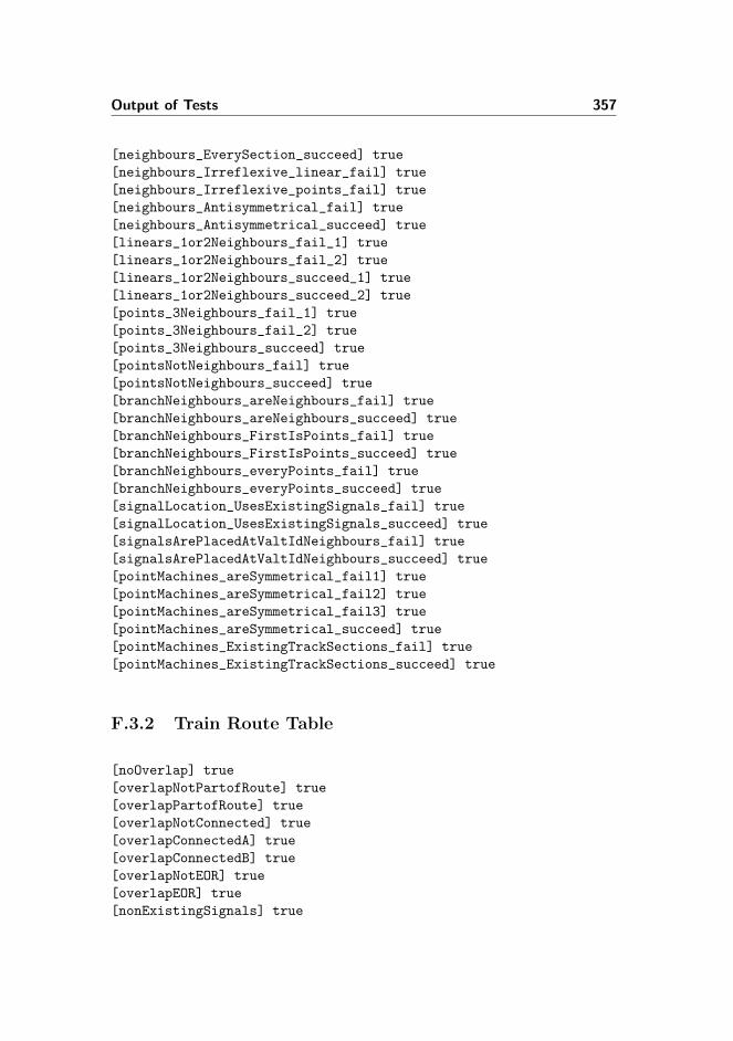
Output of Tests 357
[neighbours_EverySection_succeed] true
[neighbours_Irreflexive_linear_fail] true
[neighbours_Irreflexive_points_fail] true
[neighbours_Antisymmetrical_fail] true
[neighbours_Antisymmetrical_succeed] true
[linears_1or2Neighbours_fail_1] true
[linears_1or2Neighbours_fail_2] true
[linears_1or2Neighbours_succeed_1] true
[linears_1or2Neighbours_succeed_2] true
[points_3Neighbours_fail_1] true
[points_3Neighbours_fail_2] true
[points_3Neighbours_succeed] true
[pointsNotNeighbours_fail] true
[pointsNotNeighbours_succeed] true
[branchNeighbours_areNeighbours_fail] true
[branchNeighbours_areNeighbours_succeed] true
[branchNeighbours_FirstIsPoints_fail] true
[branchNeighbours_FirstIsPoints_succeed] true
[branchNeighbours_everyPoints_fail] true
[branchNeighbours_everyPoints_succeed] true
[signalLocation_UsesExistingSignals_fail] true
[signalLocation_UsesExistingSignals_succeed] true
[signalsArePlacedAtValtIdNeighbours_fail] true
[signalsArePlacedAtValtIdNeighbours_succeed] true
[pointMachines_areSymmetrical_fail1] true
[pointMachines_areSymmetrical_fail2] true
[pointMachines_areSymmetrical_fail3] true
[pointMachines_areSymmetrical_succeed] true
[pointMachines_ExistingTrackSections_fail] true
[pointMachines_ExistingTrackSections_succeed] true
F.3.2 Train Route Table
[noOverlap] true
[overlapNotPartofRoute] true
[overlapPartofRoute] true
[overlapNotConnected] true
[overlapConnectedA] true
[overlapConnectedB] true
[overlapNotEOR] true
[overlapEOR] true
[nonExistingSignals] true
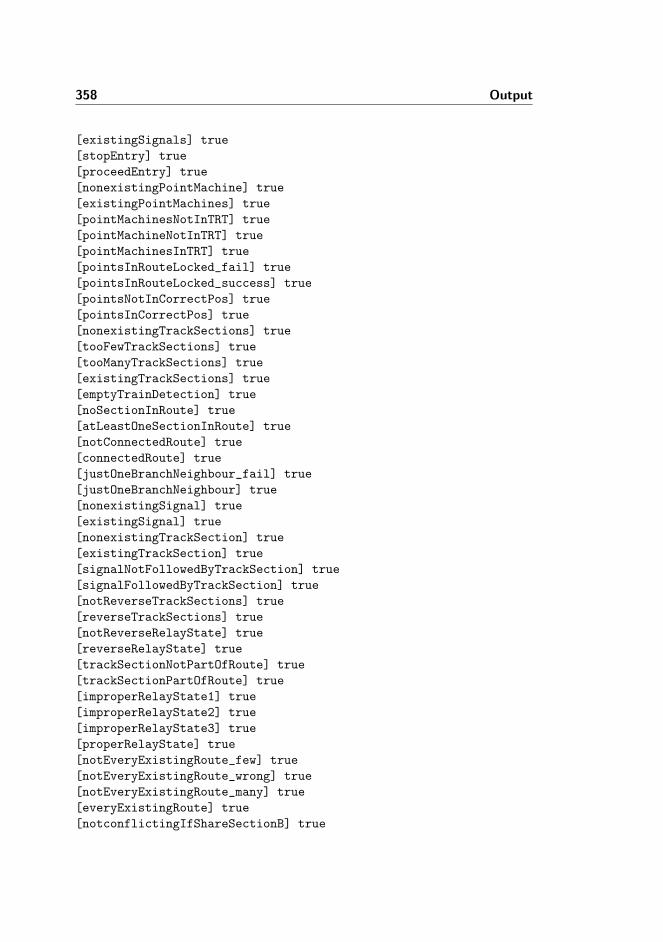
358 Output
[existingSignals] true
[stopEntry] true
[proceedEntry] true
[nonexistingPointMachine] true
[existingPointMachines] true
[pointMachinesNotInTRT] true
[pointMachineNotInTRT] true
[pointMachinesInTRT] true
[pointsInRouteLocked_fail] true
[pointsInRouteLocked_success] true
[pointsNotInCorrectPos] true
[pointsInCorrectPos] true
[nonexistingTrackSections] true
[tooFewTrackSections] true
[tooManyTrackSections] true
[existingTrackSections] true
[emptyTrainDetection] true
[noSectionInRoute] true
[atLeastOneSectionInRoute] true
[notConnectedRoute] true
[connectedRoute] true
[justOneBranchNeighbour_fail] true
[justOneBranchNeighbour] true
[nonexistingSignal] true
[existingSignal] true
[nonexistingTrackSection] true
[existingTrackSection] true
[signalNotFollowedByTrackSection] true
[signalFollowedByTrackSection] true
[notReverseTrackSections] true
[reverseTrackSections] true
[notReverseRelayState] true
[reverseRelayState] true
[trackSectionNotPartOfRoute] true
[trackSectionPartOfRoute] true
[improperRelayState1] true
[improperRelayState2] true
[improperRelayState3] true
[properRelayState] true
[notEveryExistingRoute_few] true
[notEveryExistingRoute_wrong] true
[notEveryExistingRoute_many] true
[everyExistingRoute] true
[notconflictingIfShareSectionB] true

Output of Tests 359
[conflictingIfShareSection] true
[notConflictingWhenDifferentPos] true
[conflictingWhenDifferentPos_samePos] true
[conflictingWhenDifferentPos] true
F.3.3 Transition System
[emptySystemName] true
[nonemptySystemName] true
[identicalIds] true
[uniqueIds] true
[invalidIds] true
[validIds] true
[emptyTransitionName] true
[nonemptyTransitionName] true
[identicalTransitionNames] true
[uniqueTransitionNames] true
[nonExistingIdsInGuard] true
[existingIdsInGuard] true
[emptyAssignment] true
[nonemptyAssignment] true
[assignToNonexistingIds] true
[assignToExistingIds] true
[idUpdMoreThanOnce] true
[idUpdOnlyOnce] true
[emptyAssertionName] true
[nonemptyAssertionName] true
[identicalAssertionNames] true
[uniqueAssertionNames] true
[nonexistingVars] true
[existingVars] true
F.3.4 Object Relay Associations
[noRelayVariableOverlap_failA] true
[noRelayVariableOverlap_failB] true
[noRelayVariableOverlap_failC] true
[noRelayVariableOverlap_failD] true
[noRelayVariableOverlap_failE] true
[noRelayVariableOverlap_failF] true

360 Output
[noRelayVariableOverlap_failG] true
[noRelayVariableOverlap_failH] true
[noRelayVariableOverlap_ok] true
[routeAssoc_fail] true
[routeAssoc_ok] true
[trackAssoc_fail] true
[trackAssoc_ok] true
[pointAssoc_existing_fail] true
[pointAssoc_different_fail1] true
[pointAssoc_different_fail2] true
[pointAssoc_ok] true
[signalAssoc_existing_fail] true
[signalAssoc_different_fail] true
[signalAssoc_ok] true
F.3.5 Train Movement Associations
[noRelayVariableOverlap_failA] true
[noRelayVariableOverlap_failB] true
[noRelayVariableOverlap_failC] true
[noRelayVariableOverlap_failD] true
[noRelayVariableOverlap_failE] true
[noRelayVariableOverlap_failF] true
[noRelayVariableOverlap_failG] true
[noRelayVariableOverlap_failH] true
[noRelayVariableOverlap_failI] true
[noRelayVariableOverlap_ok] true
[conVarsValidDomain_fail] true
[conVarsValidRange_fail] true
[connectionVars] true
[cntVarsValidDomain_fail] true
[cntVarsValidRange] true
[counterVars] true
[fwdVarsValidDomain_fail] true
[fwdVarsValidRange_fail] true
[directionFwdVars] true
[bwdVarsValidDomain_fail] true
[bwdVarsValidRange_fail] true
[directionBwdVars] true
[directionsValidDomain_fail] true
[bothDirections_fail] true
[directions] true