modelling of a lock system in a door subject to break-in...
TRANSCRIPT

Modelling of a Lock System in a DoorSubject to Break-in with CrowbarMaster’s thesis in Applied Mechanics
BRITTA KALLMAN
Department of Applied MechanicsCHALMERS UNIVERSITY OF TECHNOLOGYGoteborg, Sweden 2017


MASTER’S THESIS IN APPLIED MECHANICS
Modelling of a Lock System in a Door Subject to Break-in with Crowbar
BRITTA KALLMAN
Department of Applied Mechanics
Division of Dynamics
CHALMERS UNIVERSITY OF TECHNOLOGY
Goteborg, Sweden 2017

Modelling of a Lock System in a Door Subject to Break-in with CrowbarBRITTA KALLMAN
c© BRITTA KALLMAN, 2017
Examiner: Mikael EnelundSupervisor: David Fredriksson, CAE Value
Master’s thesis 2017:26ISSN 1652-8557Department of Applied MechanicsDivision of DynamicsChalmers University of TechnologySE-412 96 GoteborgSwedenTelephone: +46 (0)31-772 1000
Cover:Picture from physical break-in test at ASSA ABLOY.
Chalmers ReproserviceGoteborg, Sweden 2017

Modelling of a Lock System in a Door Subject to Break-in with CrowbarMaster’s thesis in Applied MechanicsBRITTA KALLMANDepartment of Applied MechanicsDivision of DynamicsChalmers University of Technology
Abstract
ASSA ABLOY [1] is today the global leader in door opening solutions dedicated to satisfying end-user needs forsecurity, safety and convenience. Their lock systems are certified together with different doors against break-insaccording to SS-EN 1630:2011+A1:2016 [2]. This standard specifies how long time the tests maximum shouldtake and what tools that are allowed to be used. These tests are, however, very expensive though both a newdoor and a new lock system are destroyed. The purpose of this thesis is therefore to develop a method foranalyzing the lock system in a door with the help of commercial computational software in the specific case ofa break-in with a crowbar.
A model of one of ASSA ABLOY’s lock system and a steel door with glass window are created in thecommercial Multi-Body Dynamics software Adams. A convergence study is performed on the model with helpof optimization methods in the software HEEDS. This model’s purpose is to compute stresses and deformationsin the lock system and from that analyze sensitive and exposed areas. With further development the modelcan be used to do a design optimization on the lock system.
To get a better visualization of the break-in simulation the MaxFlex tool in Adams, a tool that can handlenon linearity, is introduced. The knowledge about the tool is very limited from the beginning and after somesimulations a conclusions that Adams is not the optimal software for this problem is drawn. Without anymovements and mechanisms in the model a commercial Finite Element software is more appropriate due toshorter simulation time. Adams is adapted to relatively short time steps which is needed when movements andmechanisms are involved, but unnecessary for this model. A new model of the lock system is created in theFinite Element software Abaqus. This model is compared to measured data from a physical test and it can beseen that the deformation on the lock system has similar shape as in the physical test, but with a smaller totaldeformation.
Keywords: Lock system, Door, Crowbar, Finite Element Analyze, Adams, Abaqus, Optimization, HEEDS
i

ii

Preface
This project has been performed the spring of 2017 as a Master Thesis at the program Applied Mechanicsat Chalmers University of Technology. The project has been done for the consulting company CAE Value incooperation with ASSA ABLOY. David Fredriksson, Joel Albrektsson and Kim Bladh at CAE Value havesupervised the project. The examiner and supervisor from Chalmers Univeristy of Technology has been MikaelEnelund.
Acknowledgements
Firstly, I would like to thank ASSA ABLOY for the project concept and for letting me be a part of yourwork for making the lock system safer and hence make homes safer for everybody. An extra thank to MathiasFalt and Fredrik Parus at ASSA ABLOY for all their help and input to the work. Many thanks to DavidFredriksson, Joel Albrektsson and Kim Bladh at CAE Value for all their help and patience during my thesis.At last a wish to thank my examiner at Chalmers University of Technology, Mikael Enelund, for great supportduring the whole project.
iii

iv

Nomenclature
Abbreviations
BDF Bulk Data FileCAE Computed Aided EngineeringFE Finite ElementFEA Finite Element AnalysisFEM Finite Element MethodGUI Graphical User InterfaceMBD Multi Body DynamicsMBS Multi Body SystemsMNF Modal Neutral Files
v

vi

Contents
Abstract i
Preface iii
Acknowledgements iii
Nomenclature v
Contents vii
1 Introduction 1
1.1 Background . . . . . . . . . . . . . . . . . . . . . . . . . . . . . . . . . . . . . . . . . . . . . . . . . 1
1.2 Purpose . . . . . . . . . . . . . . . . . . . . . . . . . . . . . . . . . . . . . . . . . . . . . . . . . . . 1
1.3 Objectives . . . . . . . . . . . . . . . . . . . . . . . . . . . . . . . . . . . . . . . . . . . . . . . . . . 1
1.4 Delimitations . . . . . . . . . . . . . . . . . . . . . . . . . . . . . . . . . . . . . . . . . . . . . . . . 1
1.5 Company presentation . . . . . . . . . . . . . . . . . . . . . . . . . . . . . . . . . . . . . . . . . . . 1
1.6 Literature study . . . . . . . . . . . . . . . . . . . . . . . . . . . . . . . . . . . . . . . . . . . . . . 2
2 Theory 2
2.1 Optimization . . . . . . . . . . . . . . . . . . . . . . . . . . . . . . . . . . . . . . . . . . . . . . . . 2
2.1.1 SHERPA . . . . . . . . . . . . . . . . . . . . . . . . . . . . . . . . . . . . . . . . . . . . . . . . . 3
2.2 ASCII . . . . . . . . . . . . . . . . . . . . . . . . . . . . . . . . . . . . . . . . . . . . . . . . . . . . 3
2.3 ANSA . . . . . . . . . . . . . . . . . . . . . . . . . . . . . . . . . . . . . . . . . . . . . . . . . . . . 3
2.4 Adams . . . . . . . . . . . . . . . . . . . . . . . . . . . . . . . . . . . . . . . . . . . . . . . . . . . . 3
2.4.1 Adams MaxFlex . . . . . . . . . . . . . . . . . . . . . . . . . . . . . . . . . . . . . . . . . . . . . 4
2.5 MSC Nastran . . . . . . . . . . . . . . . . . . . . . . . . . . . . . . . . . . . . . . . . . . . . . . . . 4
2.6 Abaqus . . . . . . . . . . . . . . . . . . . . . . . . . . . . . . . . . . . . . . . . . . . . . . . . . . . 4
3 Geometry 4
3.1 Lock system . . . . . . . . . . . . . . . . . . . . . . . . . . . . . . . . . . . . . . . . . . . . . . . . . 4
3.2 Door and door frame . . . . . . . . . . . . . . . . . . . . . . . . . . . . . . . . . . . . . . . . . . . . 8
4 Loading case 9
5 Method 10
5.1 Rigid Body model . . . . . . . . . . . . . . . . . . . . . . . . . . . . . . . . . . . . . . . . . . . . . 11
5.1.1 Geometry . . . . . . . . . . . . . . . . . . . . . . . . . . . . . . . . . . . . . . . . . . . . . . . . . 11
5.1.2 Connections, contacts and forces . . . . . . . . . . . . . . . . . . . . . . . . . . . . . . . . . . . . 11
5.2 Mixed flexible and rigid body model . . . . . . . . . . . . . . . . . . . . . . . . . . . . . . . . . . . 13
vii

5.2.1 Geometry . . . . . . . . . . . . . . . . . . . . . . . . . . . . . . . . . . . . . . . . . . . . . . . . . 13
5.2.2 Clean up and meshing of flexible bodies . . . . . . . . . . . . . . . . . . . . . . . . . . . . . . . . 13
5.2.3 Adams model . . . . . . . . . . . . . . . . . . . . . . . . . . . . . . . . . . . . . . . . . . . . . . . 15
5.3 Convergence studies . . . . . . . . . . . . . . . . . . . . . . . . . . . . . . . . . . . . . . . . . . . . 18
5.4 HEEDS structure . . . . . . . . . . . . . . . . . . . . . . . . . . . . . . . . . . . . . . . . . . . . . . 19
5.5 MaxFlex model . . . . . . . . . . . . . . . . . . . . . . . . . . . . . . . . . . . . . . . . . . . . . . . 21
5.5.1 Striking plate . . . . . . . . . . . . . . . . . . . . . . . . . . . . . . . . . . . . . . . . . . . . . . . 21
5.5.2 Door frame . . . . . . . . . . . . . . . . . . . . . . . . . . . . . . . . . . . . . . . . . . . . . . . . 22
5.6 Abaqus model . . . . . . . . . . . . . . . . . . . . . . . . . . . . . . . . . . . . . . . . . . . . . . . 23
5.7 Verification of Abaqus model of the lock system . . . . . . . . . . . . . . . . . . . . . . . . . . . . . 25
5.7.1 Measure data . . . . . . . . . . . . . . . . . . . . . . . . . . . . . . . . . . . . . . . . . . . . . . . 27
6 Results 28
6.1 Mixed flexible and rigid model . . . . . . . . . . . . . . . . . . . . . . . . . . . . . . . . . . . . . . 28
6.2 Convergence studies . . . . . . . . . . . . . . . . . . . . . . . . . . . . . . . . . . . . . . . . . . . . 28
6.2.1 Time step size . . . . . . . . . . . . . . . . . . . . . . . . . . . . . . . . . . . . . . . . . . . . . . 28
6.2.2 Element size . . . . . . . . . . . . . . . . . . . . . . . . . . . . . . . . . . . . . . . . . . . . . . . 30
6.3 Non linear material model in Adams - MaxFlex . . . . . . . . . . . . . . . . . . . . . . . . . . . . . 31
6.3.1 MaxFlex model of striking plate . . . . . . . . . . . . . . . . . . . . . . . . . . . . . . . . . . . . 31
6.3.2 MaxFlex model of door frame . . . . . . . . . . . . . . . . . . . . . . . . . . . . . . . . . . . . . . 32
6.4 Verification of Abaqus model of the lock system . . . . . . . . . . . . . . . . . . . . . . . . . . . . . 33
7 Discussion 35
7.1 Software . . . . . . . . . . . . . . . . . . . . . . . . . . . . . . . . . . . . . . . . . . . . . . . . . . . 35
7.2 Verification of Abaqus model . . . . . . . . . . . . . . . . . . . . . . . . . . . . . . . . . . . . . . . 35
8 Future work 36
References 37
A BDF for MNF generation of the flexible bodies I
B Simulation script used in HEEDS for running the Adams simulation II
C BDF parameters for the MaxFlex model of the striking plate III
D BDF parameters for the MaxFlex model of the door frame IV
viii

1 Introduction
This project consist of modeling a lock system in a door subjected to break-in. In this chapter it is presentedwhat the benefits of this kind of modeling could be, the objectives of the project and what limitations that areassumed.
1.1 Background
A break-in to ones home is today something that scares many people. A strengthening of the doors and locksystem would therefore make people feel safer but it would also result in less police resources for solving break-incases.
ASSA ABLOY [1] is today the global leader in door opening solutions dedicated to satisfying end-user needs forsecurity, safety and convenience. Their lock systems are certified together with different doors against break-insaccording to SS-EN 1630:2011+A1:2016 [2]. This standard specifies how long time the tests maximum shouldtake and what tools that are allowed to be used. However, how the tools are to be used and with what forceare not specified. This means that the test could be extremely different from time to time and it is difficult topredict the result.
Though ASSA ABLOY wants to make the locks even more safe for their customer and the fact that the testsare expensive and hard to predict the subject of this master thesis is to develop a novel method for analyzingand simulating lock systems with respect to break-in loads without the need of physical testing.
1.2 Purpose
The purpose of this master thesis is to develop a novel method to visualize, simulate and analyze the locksystem in doors, in the specific case of break-in with a crowbar.
1.3 Objectives
The main goal is to obstruct the break-ins for thieves. By creating a method for visualizing, simulating andanalyzing the lock system in a door in the specific case of a break-in with a crowbar, the lock system, togetherwith the door, can be approved to handle the real physical test without actually doing one. This is one step onthe way to improve the lock system since, with a complete model, the stress distribution and deflection canbe calculated and exposed areas can be identified. To verify the model of the lock system the results from asimple loading case will be compared to measure data from a physical test done by ASSA ABLOY. To do allthis the computer programs ANSA [3], Adams [4], MSC Nastran [5] and Abaqus [6] will be used and combined.Convergence studies will be done to verify the mesh size and time step size. The studies will be done in HEEDS[7] with the use of optimization methods.
1.4 Delimitations
The CAD-models for both the lock system and the door are input data but only the lock system is to beanalyzed. The process only includes established computer programs but probably together with own writtenuser script. The loading case is not specified exactly in the standard and needs to be limited and somehowdefined. Multiple different tools are allowed according to the standard, but only the crowbar will be accountedfor here.
1.5 Company presentation
CAE Value [8] is a consulting company specializing in optimization analytics and Multi Body Simulations(MBS). The company was founded in 2005 with the vision to accelerate the development and increasing thevalue of functional virtual prototypes.
1

1.6 Literature study
A pre-study to find earlier similar projects has been done. With searches for (“optimization” OR “calculation”OR “Finite Element”) AND “lock”, nothing similar was found. The only optimization projects found on locksystem are focused on the keys and therefore not relevant for this project. Therefore the literature study isexpanded further to similar applications and also background for methods to be used in this project.
In the standard for break-in in doors [2] it is not specified how and where the load should be applied, only whattools that are allowed and how long time they are allowed to take. If looking at standards on cars instead moredetailed information can be gained. There are, for example, standards for Side Impact Protection [9] which isa standard for what maximum impact on the car that is allowed when it is hit with a rigid steel cylinder atthe side doors. In this standard there are specifications on the impact of the door opening during and after acrash such as the door that is struck by the moving deformable barrier should not separate totally from thecar. There are also specifications for any door not struck by the moving deformable barrier, these are that thedoor shall not disengage from the latched position, the latch shall not separate from the striker, and the hingecomponents shall not separate from each other or from their attachment to the vehicle and last, neither thelatch nor the hinge systems of the door shall pull out of their anchorages. With more specific standards asthis it is more straightforward to create finite element analysis that are conformable to the physical tests andtherefore it is easier to find documentation on calculations on car doors than on house doors.
In [10] HEEDS is efficiently used to minimize the mass of a vehicle door with constraints on stress anddisplacement in five different loading cases. Three of these cases are in some way similar to this project thoughthe force is applied on the doors latch. The first loading case is a vertical force on the latch when the door isfully open to control that the sag is not to large. The second loading case is a horizontal load applied to thelatch, pushing the door into an over-open condition. The third loading case is the one most similar to thisproject, when a rotational acceleration is applied to the door with the latch constrained. The values of theconstraints on the displacement and stress are not presented in this report but with given design variables (ofgeometry lengths) HEEDS generated a result of a mass reduction on 4.36 %.
HEEDS optimization process has been applied to several automotive lower compartment wail designs, whereperformance been improved significantly and mass reductions of 20 % has been gained. This is compared tobaseline rails designed by experienced engineers [11].
2 Theory
2.1 Optimization
Optimization is a method for finding the best possible solution [12] to, for example, a design problem with agiven set of constraints. To do this it is important to formulate an effective goal (or objective), for example, whataspect of the design that need improvements. The objective is formulated from measurable values (individuallyor a combination of them) to be minimized or maximized. The optimization formulation must also includelimitations or restrictions (or constraints) and could, for example, be limitations on the size of the product,how much force it must be able to handle or physical laws and relations.
For the verification process, based on an optimization method, the computer program HEEDS [7] will be used.HEEDS can be linked together with any commercial or proprietary CAE (Computed Aided Engineering) toolthat creates input and/or output files in ASCII format (see Section 2.2). The default search method in HEEDSis SHERPA (see Section 2.1.1) which uses multiple search strategies simultaneously and also dynamically adaptsto the problem as it learns about the design. HEEDS, in comparison to Matlabs optimization algorithmsLSQNONLIN and FMINCON, provides a much user friendlier environment through its graphical user interface[13]. For the evaluation the setup in the program is the same as for an optimization process besides from thatthe study will be set to Evaluation only instead of Optimization. This means that for each evaluation thedesign variables are fixed and hence no optimization will be done. The study in HEEDS will connect multipleprograms, a simplified flow chart for this is seen in Figure 2.1.
2

ANSA NastranPre pro-cessing
AdamsSimulation
Dataextraction
Nastran-file MNF
Data Set File Result file
Figure 2.1: Simplified expected flow chart of HEEDS structure.
2.1.1 SHERPA
SHERPA stands for Simultaneous Hybrid Exploration that is Robust, Progressive and Adaptive [14]. SHERPAuses the elements of multiple search methods (both global and local methods) simultaneously in a uniquemixture and therefore takes advantage of the best attributes of each method. Each participating approachcontains internal tuning parameters which are modified automatically during the process according to knowledgegained about the design space. This knowledge also determines when and to what extent each approachcontributes to the search. In other words, SHERPA adapts itself to do the search as efficient as possible,independent on how the design space is constructed.
The advantage of SHERPA is that it is fast (needs fewer iterations than most other algorithms), robust(identifies better-quality solutions) and no tuning parameters are needed, only the specific number of evaluationswanted to conduct [14]. In [15] five different optimization problems are solved with four different optimizationmethods: SHERPA, Adaptive Simulated Annealing (ASA), Genetic Algorithm (GA) and Sequential QuadraticProgramming (NLPQL). The efficiency of the method can be measured in two ways, by the number ofevaluations required to fully convergence and the quality of the solution at a given number of evaluations.In both those measures SHERPA was found to be at least twice as good as the next best method. Besidesfrom this, all methods but SHERPA had a great variations in the performance depending on the problem.SHERPA however, is attributed to its hybrid and adaptive formulation which makes it robust over a widerange of problems.
2.2 ASCII
ASCII stands for American Standard Code for Information Interchange is a standard of character encoding[16]. It represents text in computers and other technical devices. More information on how ASCII arised, howit works and why it is designed as it is can be read in [17] and [18].
2.3 ANSA
ANSA is an advanced multidisciplinary CAE pre-processing tool which provides all the necessary functionalityfor full-model build up [3]. ANSA has everything from CAD data to ready-to-run solver input file, in a singleintegrated environment. It has an integrated Batch Meshing tool which leads to controllable and effortlessoptimal results, for both shell and volume meshing.
2.4 Adams
Adams is a Multibody Dynamics (MBD) Simulation software and therefore helps study the dynamics of movingparts, and how loads and forces are distributed throughout mechanical systems. The program offers earlysystem-level design validation and complex interactions between disciplines can be evaluated and managed [4].
3

2.4.1 Adams MaxFlex
Adams MaxFlex is a tool in Adams which allows for the representation of geometric nonlinearity (largedeformations), material nonlinearity and boundary condition nonlinearity. The tool’s focus is to providea solution for problem with both nonlinear behavior and motions and loads that influence each other and,therefore, accurate results are hard to gain through separate MBD and Finite Element Analyses (FEA) [19].
2.5 MSC Nastran
MSC (MacNeal-Schwendler Corporation) Nastran (hereafter referred to as Nastran) is an application used toperform static, dynamic, and thermal finite element analyses across the linear and nonlinear domains. It canalso handle automated structural optimization and embedded fatigue analyses [5].
2.6 Abaqus
Abaqus is a FEA product suited for engineering problems in a great variation of applications, such as dynamicvibrations, MBS, crash simulations, nonlinear static and thermal coupling [6].
3 Geometry
In this chapter the origin model of the lock system and door are presented.
3.1 Lock system
The studied lock system is the electromechanical lock 850C-50 from ASSA ABLOY, see Figure 3.1. The lock isonly examined in the locked state with the Hookbolt fully extended, and is, thus, not represented in any otherstate in this report. The lock system has approximately 35 different parts excluding screws. However, for thepurposes of this project some parts are excluded since it is assumed that electric components and the drillprotection plate do not affect the mechanical strength of the system. The model is then simplified further bymerging parts to decrease the total number of parts. When merging parts together the friction between theparts is assumed to be of negligible importance and therefore do not need to be considered in the simulation.The final number of parts in the simplified lock model is 13 different parts excluding screws. The parts andpart names can be seen in Figure 3.2-3.5. This version of the lock is hereafter referred to as the lock system.The Face plate together with the Coverplate and Case are henceforth called the lock house. In Table 3.1 alllock parts material data used are presented.
4

Table 3.1: Used material data for parts in the lock system.
Part name Material Density, ρ Young’s modulus, E Poisson’s ratio, ν[kg/m3] [GPa] [-]
Case EN 1.0327* 7 870 210 0.29Coverplate EN 1.0327 7 870 210 0.29Cylinder follower Zamak 2 [20] 6 600 85.5 0.27Cylinder housing Zamak 2 6 600 85.5 0.27Face plate classified 7 900 200 0.29Hookbolt 16NiCrS4 [21] 7 800 210 0.3Hookbolt support EN 1.0083 [22] 7 850 220 0.29Latchbolt AISI 1010 [23] 7 870 205 0.29Latchbolt arm EN 1.0044 [24] 7 860 200 0.29Latchbolt guide EN 1.0327 7 870 210 0.29Motor holder ABS [25] 1 040 2.62 0.35
Motor unit - 750** - -Motor bracket EN 1.0327 7 870 210 0.29Screws S235JR [26] 7 800 210 0.3
Figure 3.1: ASSA ABLOY’s electromechanical lock 850C-50.
*Material data for EN 10327 is not found but though similar materials (low carbon metals) all had the same values for thesought data (according to the material database CES EduPack 2016 ), EN 10327 is assigned these values.
**Approximated density based on similar motors information found on different websites.
5

Face plate
Case
Hookbolt
Latchbolt
Figure 3.2: Lock system from left side.
Face plate
Coverplate
Hookbolt
Latchbolt
Figure 3.3: Lock system from right side.
Face plate
Hookbolt support
Hookbolt
Latchbolt
Latchbolt guide
CaseCylinder follower
Cylinder housing
Motor holder Motor unitLatchbolt arm Motor bracket
Coverplate
Figure 3.4: Explode view of the lock system.
6

Cylinder housing
Face plate
Coverplate
Cylinder follower
Motor holder
Motor bracket
Motor unit
Latchbolt arm
Hookbolt
Hookbolt support
Latchbolt
Latchbolt guide
Figure 3.5: The simplified lock system with its parts named. The Case (see Figure 3.2) is hidden to easier seethe other parts.
7

3.2 Door and door frame
The door used in these calculations is a steel door with glass windows. The door has a tree core and bentsteel plate on the core’s both sides, see Figures 3.6-3.7. These parts are attached together with clinching, seeFigures 3.8-3.9. Figure 3.10 shows the CAD-model of the door and door frame. The material for each part andcorresponding parameter values are found in Table 3.2.
Figure 3.6: Cross section of door. Dotted areain the middle is the tree core and the black linesbelow and above are bent steel plates.
Figure 3.7: Cross section of door frame. Dottedarea in the middle is the tree core and the blacklines below and above are bent steel plates.
Table 3.2: Used material data for parts used in door and door frame.
Part name Material Density, ρ Young’s modulus, E Poisson’s ratio, ν[kg/m3] [GPa] [-]
Tree core MDF [27][28] 400 2.9 0.25Steel plate frame S235JR 7 800 210 0.3Glass glass [29] 3 330 70 0.25Screws S235JR 7 800 210 0.3
Figure 3.8: Steel frame structure for one ledge of the door with approximate positions and structure for theclinches between the steel frame’s two parts. The tree core is not visible in the picture but is in the door placedbetween the steel frame parts with the clinching through it.
Figure 3.9: Distance in mm between clinches in the door and door frame.
8

Figure 3.10: CAD-model of door and door frame. Gray parts are made of steel and blue parts are made of glass.
4 Loading case
According to the standard SS-EN 1630:2011+A1:2016 [2] the door frame should be mounted into a substantialsteel frame with movable steel supports. This frame should be able to hold a force of 15 kN at any of thedefined points with a maximum deflection of 5 mm (see the standard for more specifics). The door frame isthen mounted in tree beams in this steel frame, see Figure 4.1.
Figure 4.1: Door mounted in tree beams in steel frame before physical test performed according to SS-EN1630:2011+A1:2016 [2].
The crowbar is included in the resistance class 3 and all allowed tools according to the standard can be seen inTable 4.1 and Figure 4.2. Here the loading case will be simplified and only the effect from the crowbar will beaccounted for. From measured tests done by Peter Blomgren at RISE (Research Institutes of Sweden) [30] thecrowbar can create applied forces on the door with a magnitude of 23-30 kN.
9

Table 4.1: Permitted tools according to resistance class 3 [2].
No Tool name Size and level1 Screwdriver Flat blade, length (365 ± 25) mm, blade width (16 ± 2.2) mm1 Pipe wrench Length (240 ± 20) mm2 Plastic wedges Length (200 ± 25) mm, width (80 ± 10) mm, height (40 ± 5) mm2 Wood wedges Length (200 ± 25) mm, width (80 ± 10) mm, height (40 ± 5) mm1 Compass saw With two bimetal or HSS blades, total length (310 ± 25) mm1 Pad saw With two bimetal or HSS blades, total length (310 ± 25) mm1 Hacksaw With two bimetal or HSS blades, blade length (330 ± 30) mm1 Steel extension tube Length (500 ± 5) mm, outer diameter (30 ± 0.5) mm, maximum wall thickness
(3 ± 0.3) mm
Figure 4.2: Allowed break-in tools in resistance class 3 according to SS-EN 1630:2011+A1:2016 [2].
5 Method
The developing of the method for analyzing the loading case is elaborated in steps, starting with a very simplified(rigid body) model, see Section 5.1, just to set up the process between the different software. CAD-models ofthe door, door frame and lock system are given and those are imported as rigid bodies into Adams. Some partsof the lock system have been removed or merged as mentioned in Section 3.1. How the door and door frameare divided into sub parts is described in Section 5.1.1. The different parts in the Adams model are connectedto each other with fixed joints, a contact force is created between the bolts and the door frame and a dragforce is applied at the door some distance below the lock, see Section 5.1.2 for more details. This model isthen implemented in HEEDS with only one run. No optimization is done here, only a first evaluation to seethat the process works. The HEEDS process will be described in Section 5.4 with the convergence study partimplemented.
With a working process for the first model, an improved model is developed. In this second set-up the goal isto get some information of relevance from the results, but still have the model as simple as possible. The door,door frame and lock house are therefore remade as flexible bodies instead of rigid bodies and imported into theAdams model. This model is then implemented in the HEEDS process and a new evaluation is done. Stresshot spots are output from the Adams model by the use of the FEMData function. To illustrate where thesestresses occur a short script in MATLAB is written, these results can be seen in Section 6.1.
To validate the simulations a couple of convergence studies have been done on the mesh element size and thetime steps size, see Section 5.3 for details. The whole process in HEEDS and how the different software arecoupled is described in Section 5.4.
Though a visualization of the physical break-in test is of interest the Adams package MaxFlex is introduced.This introduces the possibility of nonlinear material models and therefore the material is allowed to plasticize.
10

The first goal is to implement a nonlinear material model on one part in the model, in this case the doorframe, and analyze the advantage and disadvantage of MaxFlex. But though the knowledge about MaxFlex islimited, an even more simple model is used first, in this case the striking plate. The nonlinear material model isapplied to the part and more details about the method are given in Section 5.5. When this works the nonlinearmaterial model is applied to the door frame.
The MaxFlex tools give realistic results for the plasticizing but the simulation time is, however, rather long, muchlonger than with a common Finite Element Method (FEM) software. This problem, without any mechanisms,gets no advantages by using Adams MaxFlex. Therefore the model is recreated in Abaqus and most of the locksystem model was provided by CAE Value. However, some parts and contacts needed to be added before themodel was complete, Section 5.6.
The model of the lock system in Abaqus is verified against measured data from physical tests done by ASSAABLOY. The lock system is exposed for a simple loading case and the deflection is measured, see Section 5.7for further details.
5.1 Rigid Body model
This set-up exists of only rigid bodies which are connected to each other in Adams, see Section 5.1.1-5.1.2 forgeometry description and connections in Adams. The goal with the first set-up is to create the working processto have a good base that can be developed further.
5.1.1 Geometry
The lock system is divided in parts as described in Section 3.1 with the addition of the Drill protection whichis a steel plate placed on the outside of the Coverplate. The Drill protection is later on removed due to that itis not force bearing and therefore its impact is neglected. The door frame is in this version of the model in onepart, with an average density calculated from the total mass of the tree core and steel plates. First the door isremade to only have one hole for the lock system, instead of three holes that are in the origin model. Thisremaking is mostly for the visual part since the strengthening of the door because of this is negligible. Thedoor is then divided into four sub parts; door shell (steel plates), door filling (tree core), lower glazing andupper glazing. This resulted in a total of 19 parts in the Adams model.
5.1.2 Connections, contacts and forces
All connections, but the hinges, are fixed joints located in origin, which position can be seen in Figures 5.1-5.3.The location has no impact on the result when there is only rigid bodies and fixed joints. The hinges thatconnect the door to the door frame are connected with one spherical joint at the upper hinge and one inlineprimitive joint at the lower hinge. The spherical joint allows free rotation around a fixed point which meansthat all translational degrees of freedom are locked. The inline primitive joint constraints the first part so thatit only can move along a straight line defined on the second part. This means that it locks the parts in tworotations (around x- and z-axis). This results in that five of six degrees of freedom are locked for the doorrelative the door frame. The only degree of freedom that is free is the rotation around the hinges local z-axis,so that the door can open. All connections made in the Adams model in the first set-up are listed in Table 5.1.
11

x
y
F
Figure 5.1: Model with zoom box for thecoordinate systems position.
x
y
Figure 5.2: Zoom box for the coordinatesystems position.
z
y
Figure 5.3: Coordinatesystem position fromside view.
Table 5.1: Connections in Adams model in the first set-up.
Connection Type First Body Second Body CommentFixed Joint Door frame Ground Locks whole model to the ground.Spherical Joint Door shell Door frame Lower hinges connection, locking three of
six degrees of freedom (all translational).Inline Primitive Joint Door shell Door frame Upper hinges connection, locking two of
six degrees of freedom (two rotational).Fixed Joint Door filling Door shell Keeps the door as one part.Fixed Joint Lower glazing Door shellFixed Joint Upper glazing Door shellFixed Joint Case Door shellFixed Joint Coverplate CaseFixed Joint Drill protection CoverplateFixed Joint Face plate CoverplateFixed Joint Hookbolt support Face plateFixed Joint Hookbolt Hookbolt supportFixed Joint Motor holder Hookbolt supportFixed Joint Motor unit Motor holderFixed Joint Motor bracket Motor unitFixed Joint Latchbolt guide Motor holderFixed Joint Latchbolt Latchbolt guideFixed Joint Cylinder housing Face plateFixed Joint Cylinder follower Cylinder housingFixed Joint Latchbolt arm Latchbolt guide
12

The implemented contacts are between the bolts (Hookbolt and Latchbolt) and the door frame. To createthe contacts some settings are defined; a material stiffness that is used to calculate the normal force for theimpact model, damping constant that defines the damping properties for the contacting material, penetrationdepth at which depth Adams turns on full damping and a force exponent that is used to calculate the normalforce according: ( stiffness·penaltyexponent ). The values of the settings can be seen in Table 5.2. This isto hold the door closed, even when a drag force is applied. The drag force is applied on the door at location(x,y,z)=(-0.6,0,0) m, see point F in Figure 5.1, with a magnitude of 2 300 N in negative z-direction. The exactlocation and magnitude of the force in this model is not of importance though the model is only created to setup the process.
Table 5.2: Settings for the contact force.
Stiffness 2000 MN/mForce Exponent 2.2Damping 1 kN·sec/mPenetration Depth 1 · 10−5 m
5.2 Mixed flexible and rigid body model
In the second set-up the model is developed one step further and some flexible bodies are introduced. Thedoor, door frame and lock house are developed to flexible bodies in ANSA, remade to Modal Neutral Files(MNF) and then implemented in Adams. The remaking of to MNFs is done by exporting the ANSA-file as aNastran-file and then running a Bulk Data File (BDF) in Nastran which generates the MNF, see Appendix Afor BDF used here. More detailed descriptions about the meshing, connections and other settings can be foundin Sections 5.2.2-5.2.3. From this set-up more realistic results are presented and an evaluation of how realisticthe models is could be done, see Section 6.1.
5.2.1 Geometry
When remaking the parts to flexible bodies, some parts in Adams are merged. The Face plate, Coverplate andCase together creates the flexible body lock house. The door is also divided into more than one part in thefirst set-up, but here these parts only are separated in the ANSA model for the possibility to have differentmaterials. The door frame is kept as one part. The Drill protection is from hereon removed due to that itsstrengthening is negligible. This results in 13 parts in the Adams model.
5.2.2 Clean up and meshing of flexible bodies
The meshing of the flexible bodies are made in ANSA and all parts are first “cleaned up” in the program. Smallerrors that occurred when importing the geometry are corrected and surfaces with very small areas are mergedto simplify the model. Most of the parts are modelled as shell elements by first creating a mid surface of thegeometry. All screws are modelled as beam elements, this neglects pre-stresses, friction forces and contactforces but these are in this stage neglected due to that they are not expected to have any significant impact onthe result.
The tree core in the door and the tree core and striking plate in the door frame are modeled by solid elements,while all the other parts (the glass and steel plates) are modelled by shell elements. The steel plates are 1.5-5mm thick and the glass is approximate 15 mm thick, therefore a simplification with shell elements are used.This can be done due to the small dimensions compared to the geometries height and width. The glass is fastento the door with 80 small rigid body elements that go between one node on the glass and one on the door (alsocalled RBE2). An example of one of those can be seen in Figures 5.4-5.6. The clinching between the tree coreand the steel frames are modelled as beam elements. The contacts for the beam elements are spread over somefew nodes (with RBE2) to create a more accurate model, see Figure 5.6.
13

Figure 5.4: Upper part of door, gray parts are steeland tree frame while the dark yellow part is the glass.Small yellow lines between the frame and the glass areRBE2:s.
Figure 5.5: Same view as in Figure 5.4 but with allRBE2 highlighted. The part inside the red circle canbe seen enlarged in Figure 5.6.
Figure 5.6: Zoomed part from Figure 5.5. Yellow lines between the red and yellow cross are RBE2:s thatconnects the glass to the door. The blue crosses are RBE2:s that connect the beam elements that clinch the steeland tree together.
The lock house is modelled by mostly shell elements but with some beam elements for a couple of screwconnections and a small connection distance, see Figure 5.7. The mesh size is based on default mesh with somerefinements at sharp edges and other small details. The total number of elements for the three parts (door,door frame and lock house) are 171 338, and the total numbers of shell, solid respectively beam elements arefound in Table 5.3.
Table 5.3: Number of elements in the different parts.
Solid elements Shell elements Beam elements TotalDoor 23 041 32 119 264 55 424Door frame 59 497 28 461 166 88 124Lock house 19 682 8 093 15 27 790Total 102 220 68 673 445 171 338
14

Figure 5.7: Mesh of lock house without the Coverplate. Parts made by solid elements are hedged by red circles.
5.2.3 Adams model
With flexible bodies involved the locations for the fixed connections become important. A flexible body canalso have more than one fixed constraint without being overconstrained. The door frame is fastened to theground with fixed constraints at eight screw holes at its sides, see Figure 5.8. The door’s connection to thedoor frame is the same as in the first set-up, see Section 5.1.2. All connections are stated in Table 5.4 and withits position marked in Figure 5.8-5.11.
The contact force between the Hookbolt and door frame is still there to prevent the door from opening. Butthe contact force between the Latchbolt and door frame is removed due to that this bolt is easily pressed induring a real break-in and therefore does not prevent the door from open. To prevent unnatural movementcontact forces are also implemented between the door and door frame and between the lock house and door.Settings for the contact force is the same as in the first set-up, see Section 5.1.2. The drag force is appliedin the same location as before, (x, y, z)=(0,-0.6,0) m, but is this time ramped up to a maximum magnitudeof 23 kN over a time of 2.5 seconds. The door and door frame are designed to be critically damped to avoidoscillating vibrations. In Adams the linear (MNF-based) flexible body damping is done on a modal basis sincethose flexible bodies are essentially a superposition of individual modes [19].
15

Table 5.4: Connections in the mixed flexible and rigid body model.
ID ConnectionType
First Body Second Body No.* Comment
1 Fixed Joint Door frame Ground 8 Locks whole model to the groundwhere the door frame has screwholes.
2 Spherical Joint Door Door frame 1 Upper hinges connection, lockingthree of six degrees of freedom (alltranslational).
3 Inline PrimitiveJoint
Door shell Door frame 1 Lower hinges connection, lockingtwo of six degrees of freedom (tworotational).
4 Fixed Joint Face plate Door 2 Locks the lock house to the doorwith two screw holes in the Faceplate.
5 Fixed Joint Face plate Hookbolt support 16 Fixed Joint Lock house Hookbolt support 1 Fixed joints at screw holes through
lock house into the Hookbolt sup-port.
7 Fixed Joint Lock house Hookbolt support 18 Fixed Joint Case Hookbolt support 19 Fixed Joint Lock house Latchbolt arm 110 Fixed Joint Lock house Cylinder housing 111 Fixed Joint Case Cylinder housing 212 Fixed Joint Case Latchbolt guide 213 Fixed Joint Coverplate Latchbolt guide 214 Fixed Joint Case Motor holder 215 Fixed Joint Case Motor bracket 216 Fixed Joint Latchbolt Latchbolt arm 117 Fixed Joint Hookbolt Hookbolt support 118 Fixed Joint Cylinder follower Cylinder housing 119 Fixed Joint Motor unit Motor holder 1
*Number of similar joints but at different locations.
16

1
1
1
1
1
1
1
1
2
3
Figure 5.8: Door with connection positions markedwith red circles.
16
17
18
19
Figure 5.9: Lock system with connection positionmarked with red circles.
4
4
56
7
8
9
10
11
11
12
12
14
14
15
15
Figure 5.10: Lock system from left side with connec-tion positions marked with red circles.
4
4
5 6
7
9
10
1313
Figure 5.11: Lock system from right side with con-nection positions marked with red circles.
17
5.3 Convergence studies
To validate the results, some convergence studies of the mesh size and time steps size are done. This is madewith the help of the optimization software HEEDS where some design variables are defined to make a processthat creates multiple runs and presents the results. The step sizes are defined by the number of time steps andcan easily be referred to in HEEDS though it is already input settings. It is defined as a design variable andafter some preliminary elaborations it was set to vary between 50 and 1000 number of steps, which with asimulation time of one second results in time steps sizes of 1 to 20 ms. The number of time steps (or step size)in the convergence study is based on six number of evaluations. The different evaluations done are seen inTable 5.5. The results are then presented in Section 6.2.1.
Table 5.5: Convergence study evaluations of what number of time steps that are used.
Evaluation number 1 2 3 4 5 6Number of time steps 50 100 200 400 800 1000Step size [ms] 20 10 5 2.5 1.25 1
A convergence study of the mesh size is set-up in HEEDS, with the purpose of evaluating a refined mesh onall flexible bodies in each evaluation. To make the mesh size as a design variable in HEEDS, remaking ofthe ANSA models (of the flexible bodies) and loading of the MNFs are necessary. The mesh is here basedon a simple and rather coarse mesh. In each evaluation, the whole mesh is refined by the mesh refinementfunction in ANSA and therefore the mesh over the whole geometry will be finer in each evaluation. The meshrefinements convergence study is set-up for five different evaluations, the first one with the original coarse meshand then with an increasing number of refinements from one to four. This process is described in Section 5.4.
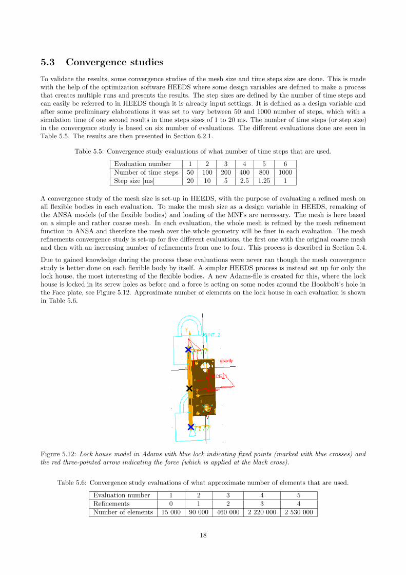
Due to gained knowledge during the process these evaluations were never ran though the mesh convergencestudy is better done on each flexible body by itself. A simpler HEEDS process is instead set up for only thelock house, the most interesting of the flexible bodies. A new Adams-file is created for this, where the lockhouse is locked in its screw holes as before and a force is acting on some nodes around the Hookbolt’s hole inthe Face plate, see Figure 5.12. Approximate number of elements on the lock house in each evaluation is shownin Table 5.6.
Figure 5.12: Lock house model in Adams with blue lock indicating fixed points (marked with blue crosses) andthe red three-pointed arrow indicating the force (which is applied at the black cross).
Table 5.6: Convergence study evaluations of what approximate number of elements that are used.
Evaluation number 1 2 3 4 5Refinements 0 1 2 3 4Number of elements 15 000 90 000 460 000 2 220 000 2 530 000
18

5.4 HEEDS structure
HEEDS is built up by boxes that have there own functions, see squares in Figure 5.13. All boxes have specifiedinput and output data and hence links the boxes together due to that ones output could be another ones input.The three boxes to the right (box number 6-8) form the base structure created according to Section 5.1. Toimplement the automatic mesh refinement in HEEDS multiple new boxes in the software are needed. Those areimplemented to the left of the first ones due to that their function should happen before the actual evaluation.For the convergence study on time step size only the boxes 6-8 are needed. All boxes’ functions and their inputand output files are presented in the list below and a simplified flow chart can be seen in Figure 5.14.
For the actual convergence study ran on mesh size of the lock house the boxes 2 and 3 are removed from theHEEDS process. Otherwise the process in HEEDS is exactly the same, even though another Adams-file in thesimulation-box is ran.
1
2
3
4
5 6 7 8
Figure 5.13: Picture of the process in HEEDS Graphical User Interface (GUI) with all boxes labeled withnumbers.
1. ANSA-box: Opens ANSA and reads an ANSA-script that refines the mesh of the flexible bodies (door,door frame and lock house) a specified number of times.
• Input: ANSA-script
• Output: Three Nastran-files, one for each flexible body
2. Nastran-box (door): Opens Nastran and runs a BDF (see Appendix A) including the output Nastran-fileof the door from box one. This generates a MNF of the part.
• Input: BDF and Nastran-file for the door
• Output: MNF of the door
3. Nastran-box (door frame): Opens Nastran and runs a BDF (see Appendix A) including the outputNastran-file of the door frame from box one. This generates a MNF of the part.
• Input: BDF and Nastran-file for the door frame
• Output: MNF of the door frame
4. Nastran-box (lock house): Opens Nastran and runs a BDF (see Appendix A) including the outputNastran-file of the lock house from box one. This generates a MNF of the part.
• Input: BDF and Nastran-file for the lock house
• Output: MNF of the lock house
5. MNF-renaming-box: Runs Python script that moves and renames the MNFs to the name and folder usedby Adams.
19

ANSANastran(door)
Nastran(door frame)
Nastran(lock house)
MNF-renaming
SimulationPre pro-cessing
Dataextraction
Nastran-file
Nastran-file
Nastran-file
MNF
MNF
MNF
MNFs Data Set File Result file
Figure 5.14: Simplified flow chart of HEEDS structure.
• Input: MNFs of the parts from box 2-4
• Output: MNFs of the parts saved with another name in the working folder for Adams folder
6. Pre-processing-box: Read the Adams database including the model and creates simulation files.
• Input: Command file that reads the Adams database of the model and changes some force parameters
• Output: Adams data set file including the model and a parasolid file
7. Simulation-box: Reads the simulation script including total simulation time and number of time steps(see Appendix B). Running the simulation and gives output about von Mises hot spot stresses in theflexible bodies.
• Input: A simulation script, Adams data set file, a parasolid file and matrix files* for each flexiblebody
• Output: A simulation running message and a document including top 15 maximum hot spot stressesin each flexible body.
8. Data extraction-box: Reads the simulation results and saves the contact force between the Hookbolt anddoor frame over time into a text file.
• Input: Script that saves chosen results from the simulation into a text file.
• Output: Text file with specified results.
*The matrix file contains inertia invariants and the portion of the flexible body modes shapes that correspond to markerlocations.
20

5.5 MaxFlex model
To learn about the MaxFlex tool in Adams a simple model is chosen in the first step. This is also time savingthough a smaller and simpler model need less simulation time. The striking plate, usually mounted on the doorframe, is used though it is an existing but small part. For further details see Section 5.5.1. When this model isrunning and some knowledge about the MaxFlex tool is gained the nonlinear material model is implementedon the whole door frame, see Section 5.5.2.
5.5.1 Striking plate
The striking plate is remodelled by shell elements for simplifications. The material data for this part is redefinedin ANSA to a nonlinear material, see Figure 5.15. This is done by activating the material parameter MATEP inANSA and assign it SOL400 based on a created table. The model information is imported in an BDF togetherwith some output information and parameter settings, see Appendix C for parameters used in the BDF. Thisfile is then imported in a new Adams database.
Figure 5.15: Stress-strain curve for material S235JR [31].
In Adams the striking plate is locked with fixed joints in its screw holes and a force is applied on one side ofthe inwards fold, see the black cross in Figure 5.16. The applied force is defined as a step function over a timeof 0.6 seconds with a maximum magnitude of 650 N, STEP(TIME,0,0,.6,-650). The force is applied in theopposite direction of the red force arrow in the figure. A time step of 0.8 ms is used. Deformation, stress andplastic strain are set to be output data from the simulation.
Figure 5.16: Striking plate from Adams model with fixed joints (blue locks) and applied force (red arrow pointingto the left) with its attached point in the black cross.
21

5.5.2 Door frame
The material in the door frame model is changed to a nonlinear material in the same way as for the strikingplate, see Section 5.5.1. The same material data is used. Due to a more complex model some settings in theBDF are changed to decrease the running time somewhat, see Appendix D for whole BDF. The stress output isonly saved for the steel frame and not the tree core.
In Adams the door is locked to its position by fixed joints at seven of its eights screw holes and the force isapplied at the eighth hole, see Figures 5.17-5.19. The applied force is defined as a step function over a timeof one seconds with a maximum magnitude of 23 kN, STEP(TIME,0,0,1,-23000). A step size of 4.55 · 10−4
seconds is used. Simulation settings used are presented in Table 5.7.
Figure 5.17: MaxFlex model of the door frame in Adams. Fixed joints are marked by blue locks and the redarrow on the left side symbolizes the applied force.
Figure 5.18: MaxFlex model of the door frame,zoomed in to where the force is applied at a RBE2in a screw hole.
Figure 5.19: MaxFlex model of the door frame,zoomed in to where one of the fixed joints is appliedat a RBE2 in a screw hole.
22

Table 5.7: Solver settings for MaxFlex model of door frame.
Method used for integrating the differential equations of motion: GSTIFF*
Technique used for equations describing mechanical system: I3**
Relative and absolute local integration tolerance: 10−3
Maximum integrator time step allowed: None
Evaluates the Jacobian at every iteration: TFFFTFFFTFFFTF***
(default for dynamic simulations)
5.6 Abaqus model
A model of the lock system in Abaqus is provided by CAE Value. The model contains most of the partsincluded in the simplified model of the lock system but with none of the parts merged as in the Adams model.The parts are instead fixed to each other with tie contact in Abaqus (with a position tolerance of 0.05 mm).The Latchbolt, Latchbolt arm and Motor are not yet included, see Figures 5.20-5.21. All parts that are incontact are fixed with the tie contact or with a RBE2. To prevent the Hookbolt from penetrate the partsaround it when loaded, contact pairs are created between the Hookbolt and the Face plate, Hookbolt support,Motor holder, Case and Coverplate.
The model is updated with the Latchbolt and the Latchbolt arm, see Figure 5.22. Nonlinear materials withisotropic hardening are added to the Face plate, the Coverplate, the Case, the Latchbolt guide and the Motorbracket. The materials stress-strain curves are presented in Figures 5.23-5.24. Remaining parts in the modelare given the material data stated in Table 3.1. Tie contacts are used between the Latchbolt and the Latchboltarm, the Latchbolt arm and the Case and between the Latchbolt arm and the Coverplate. To prevent theLatchbolt from penetrating the lock house contact pairs are created between the Latchbolt and the Face plateand between the Latchbolt and the Case.
Figure 5.20: FE model of the lock system.
*Integrator that uses backward differentiation formulas and fixed coefficients for prediction and correction.**Equation formulation that ensures that the solution satisfies all constraints, does not ensure that the velocities and accelerations
calculated satisfy all first- and second-time derivatives and monitors integration error only in system displacements, not in velocities.It is fast, but the Jacobian matrix can become ill-conditioned at small step sizes.***A ten character strings that together establish the pattern for evaluating the Jacobian matrix during the modified Newton-
Raphson solution for a dynamic simulation. For each iteration, T or TRUE indicates that Adams Solver is to evaluate the Jacobian,and F or FALSE indicates that Adams Solver is not to evaluate the Jacobian, instead it is to use the previously calculated Jacobianmatrix as an approximation of the current one.
23

Figure 5.21: FE model of the lock system without the Coverplate and the Case.
Figure 5.22: Developed model of the lock system without the Coverplate and the Case.
Figure 5.23: Stress-strain curve of the plastic zonefor the nonlinear material EN 1.0327, applied on theCase, Coverplate, Latchbolt guide and Motor bracket[31]. Yield limit is 186 MPa.
Figure 5.24: Stress-strain curve of the plastic zonefor the nonlinear material applied to the Face plate[31]. Yield limit is 308 MPa.
24

5.7 Verification of Abaqus model of the lock system
To verify the Abaqus model of the lock system a standardized loading case is compared with measured datafrom a physical test done by ASSA ABLOY, see picture from testing in Figure 5.25. Details about the measureddata are presented in Section 5.7.1. In the physical test the lock system is positioned horizontally in a mountingstand, see illustration in Figures 5.26-5.27. The mounting stand locks the screws in all degrees of freedoms butin the y-direction. This is to not restrain the bending when the force is applied. The force is applied at theHookbolt a distance of three millimeter from the Face plate. To prevent the lock system from tipping becauseof the force a beam is fastened above the upper side of the lock system.
Figure 5.25: Lock system locked in the mounting stand at the physical loading case.
xy
z
Figure 5.26: Simplified model of the loading case. The blue screws hold the lock fixed in all degrees of freedomsbut in the y-direction, the red beam blocks the lock’s back from tipping upwards and the green cylinder is thesteel part that applies the force.
The loading case is then applied to the Abaqus model as described here. In each screw hole, a rigid body isconnected and its center node is fixed in x- and z-directions and in all rotational degrees of freedom. A createdstiff rigid body element, fixed in its middle, symbolizes the beam that restrains the lock system from tipping,see Figure 5.28. Four forces each applied at a couple of nodes on the Hookbolt are applied to distribute theforce without stiffen the Hookbolt too much. This is done by creating four RBE2:s at the Hookbolt, see Figures5.29-5.30, and applying the forces at each RBE2’s center node. The total force magnitude is the same as at thephysical test, the force over time is plotted in Figure 5.31.
25

Figure 5.27: Simplified model of the loading case. The blue screws hold the lock fixed in all degrees of freedomsbut in the y-direction, the red beam blocks the lock from tipping forward and the green part is the steel part thatapplies the force.
Figure 5.28: Lock system in ANSA GUI (with Abaqus package active). Blue spiders are RBE2:s connecting thedifferent parts to each other or spreading the force/joint on multiple nodes. The grey part (with a big whitecross) on the locks upper back side is the stiff rigid body element.
Figure 5.29: The figure illustrates how the force isapplied to the Hookbolt in Abaqus. The blue spiders(partly hidden) are RBE2:s and the force is appliedat its center nodes, the small red dots in the spiders.
Figure 5.30: The figure illustrates how the force isapplied to the Hookbolt in Abaqus. The blue spidersare RBE2:s and the force is applied at its centernodes, the small red crosses in the spiders. All partsbut the spiders are transparent for easier visibility.
26

Figure 5.31: Force versus time measurements from physical tests.
The simulation ran for 136 seconds, to the time when the force is the highest, with automatic step size settings.The first step is 2 seconds, minimum step size allowed is 0.001 seconds and maximum step size is 3 seconds.
To evaluate how high impact the nonlinear material data has on the result some simulation with altered dataare done as well. The stress values for the two different nonlinear materials (the Face plate material and EN1.0327) are translated by approximate 5 % of its original yield limit, both in negative and positive direction, seeEvaluation 2-7 in Table 5.8. Evaluation 8-10 is with the stress translated 20 %, 30 % and 50 % in the negativedirection.
Table 5.8: Translating stress status in MPa for altered material data in each evaluation.
Evaluation 1 2 3 4 5 6 7 8 9 10Face plate material - -30 - -30 +30 - +30 -62 -92 -154EN 1.0327 - - -20 -20 - +20 +20 -37 -55 -93
5.7.1 Measure data
The physical tests performed by ASSA ABLOY give information about the load, time and movement for thecrosshead that applies the force on the Hookbolt. Two similar tests are done and the data is plotted in Figures5.32-5.33. Though the data for Test 2 is smoother, and therefore seems more realistic, this will be used tovalidate the model.
Figure 5.32: Measure data from physical test doneby ASSA ABLOY.
Figure 5.33: Measure data from physical test doneby ASSA ABLOY.
27

6 Results
6.1 Mixed flexible and rigid model
From the second set-up with a mixed flexible and rigid body some simple results are extracted. The model isstill very simplified and the force’s magnitude and location are applied without further elaborations or analyses.But with a maximum force magnitude of 23 kN at a location of (0, -600, 0) mm, 50 stress hot points areanalyzed, see the red dots in Figure 6.1. The stress range for the hot spots is 3.3-6.4 GPa.
Figure 6.1: Hot points (red dots) of stresses on lock system. Darker red and larger dots indicates higher stress.
6.2 Convergence studies
From the convergence studies the maximum von Mises stress in each flexible part is analyzed and compared forthe different designs. It is also taken into account where the maximum stress occurred, so it is in the sameplace for all designs.
6.2.1 Time step size
The maximum von Mises stress evaluated in each part for each evaluation design is plotted in Figures 6.2-6.4.The position for the maximum stress on each part is visualized in Figures 6.5-6.7. As seen in the plots thestresses are lower for the largest time step (first design ID, i.e., 20 ms), but by bisect the time step, i.e. 10 ms,a more accurate result is gained.
Figure 6.2: Convergence results of time steps sizesfor maximum von Mises stress on the lock house.
Figure 6.3: Convergence results of time steps sizesfor maximum von Mises stress on the door frame.
28
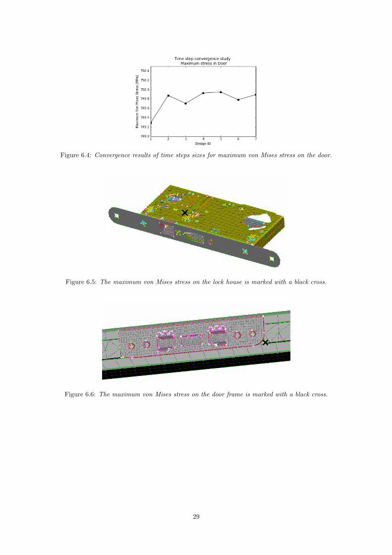
Figure 6.4: Convergence results of time steps sizes for maximum von Mises stress on the door.
Figure 6.5: The maximum von Mises stress on the lock house is marked with a black cross.
Figure 6.6: The maximum von Mises stress on the door frame is marked with a black cross.
29

Figure 6.7: The maximum von Mises stress on the door is marked with a black cross.
6.2.2 Element size
The convergence study of the mesh size gives the von Mises stress in a some nodes on the lock house. Theresults are seen in Figure 6.8. Specified nodes are marked in Figure 6.9.
Figure 6.8: Convergence results of mesh sizes for maximum von Mises stress on the lock house.
Figure 6.9: Points (marked with black cross) used to analyze the von Mises stress in the lock house to check forconvergence.
30

6.3 Non linear material model in Adams - MaxFlex
6.3.1 MaxFlex model of striking plate
With the force applied on a feature of the striking plate that only is fastened at one of its four sides the totaldisplacement, effective von Mises stress and plastic strain on the striking plate are more or less concentratedto this feature. The maximum displacement is 1.5 mm indicated by red color in Figure 6.10. The maximumeffective von Mises stress is approximate 240 MPa and is seen in Figure 6.11. The plastic strain is presented inFigure 6.12 and have a maximum value of 1.7 %.
Figure 6.10: Displacement in mm of the striking plate with a nonlinear material at time 0.6 second withmaximum load applied.
Figure 6.11: Effective von Mises stress in MPa of the striking plate with a nonlinear material at time 0.6 secondwith maximum load applied.
31

Figure 6.12: Plastic strain of the striking plate with a nonlinear material at time 0.6 second with maximumload applied.
6.3.2 MaxFlex model of door frame
The simulation of the MaxFlex model of the door frame was allowed to run for 6 days before cancelled due tothe long simulation time. During this time the model was simulated 0.489 seconds and reached a maximumforce of approximate 11 kN. The displacement, stress and strain result for the MaxFlex model of the doorframe are presented in Figures 6.13-6.15. The maximum displacement is 47 mm, maximum stress is 440 MPaand maximum plastic strain is 9 %.
Figure 6.13: Displacement in mm of the door framewith a nonlinear material at time 0.489 second withmaximum load of 11 kN applied.
Figure 6.14: Effective von Mises stress in MPa of thedoor frame with a nonlinear material at time 0.489second with maximum load of 11 kN applied.
The simulation time could have been shorten with other simulation settings and some development of thecontacts in the model. Simulation settings that had been a better choice is if the integration tolerance is set to10−2 and the Jacobian pattern is set to True (meaning that the Jacobian is evaluated each time). As seen inFigure 6.15 the contacts there need some improvement though the steel now penetrates both itself and the tree,which also slows the evaluation. However, this model will not be further analyzed due to a FE software canhandles this problem much more efficient.
32

Figure 6.15: Plastic strain of the door frame with a nonlinear material at time 0.489 second with maximumload of 11 kN applied.
6.4 Verification of Abaqus model of the lock system
The results from the verification of the Abaqus model of the lock system are presented here. The shape ofthe simulation is similar to the physical test, compare Figure 6.16 with Figure 6.17. Figure 6.18 shows theresulting effective von Mises stress in the model. These results are for evaluation one and give a maximumdeformation of approximate 9 mm and maximum stress of 4.9 GPa. The deformation result versus time foreach evaluation is shown in Figure 6.19 together with the measure from the physical test. This deformationis measured in the point marked in Figure 6.18. Table 5.8 is presented again for easier understanding of theresults, now as Table 6.1.
Figure 6.16: Deformation in mm of the lock system after simulation (evaluation number one).
Figure 6.17: Deformation of the lock system after physical test.
33

Figure 6.18: Von Mises stress results in MPa from evaluation one. Black cross marked on the Hookbolt is wherethe deformation is measured.
Figure 6.19: Deformation on the Hookbolt over time for each evaluation compared to the result from the physicaltest, i.e., Test 2 inn the legend.
Table 6.1: Translating stress status in MPa for altered material data in each evaluation.
Evaluation 1 2 3 4 5 6 7 8 9 10Face plate material - -30 - -30 +30 - +30 -62 -92 -154EN 1.0327 - - -20 -20 - +20 +20 -37 -55 -93
34

7 Discussion
7.1 Software
The model was in the beginning meant to include more mechanisms and movements and therefore Adams waschosen as simulation software. When the project now is almost done, it is clear it became a FE project insteadof a project including MBD. If this knowledge had been present in the beginning of the project another softwaremight have been chosen, but the Adams model is still accurate and can be useful for simulations in the future.
The MaxFlex tool in Adams is developed mainly for problems “where the nonlinear behavior of some partsand the motions and loads of the rest of the multibody dynamics (MBD) model influence each other, makingaccurate results impossible or impractical through separate MBD and FEA analyses” [32]. The tool works forproblems only including FEA as well, but though the software is mainly created for mechanisms and movementsit requires a small step size which results in unnecessary long simulation times. Most FE software have a moreefficient algorithm and can handle larger time steps. Therefore it is easier to shorten the simulation time.
7.2 Verification of Abaqus model
The deformation results from the simulation of the Abaqus model of the lock system have a similar shape asthe result from the physical test, but with a lower value. This could depend on multiple things. The mostlikely reason to this is probably the difference of the contacts in the model compared to how it is in reality. Inreality the parts are clamped together by the Case and Coverplate with screws, but there will always be a gapbetween the different parts. In the Abaqus model, each of the parts are tied to the Case, Coverplate or anotherpart and this results in a stiffer model. From the physical test no large movements of the parts could be seenand therefore this assumption is made. However, some unseen movements could exists within the lock houseand as the Abaqus model do not allow this movements, the deformation on the model is smaller than reality.
One geometrical difference between the Abaqus model and the lock system used in the physical test is thatthe Latchbolt is flipped. The simulation (see Figure 6.16) has the Latchbolt’s flat side upwards, while thephysical test (see Figure 6.17) has it downwards. The part of the Latchbolt that is hidden inside the lockhouse is circular and therefore similar in all directions and hence does not impact the result. But where theLatchbolt sticks out from the Face plate, there is one flat side and one slightly rounded side. The rounded sidemight make it easier for the Face plate to deform, though it both has the opportunity to press straight down inFigure 6.17, but also slide outwards on the Latchbolt. This could mean that the model is less stiff and moredeformation occur. The simulation model on the other hand have the flat side upwards towards the pressingFace plate, which could make it harder for the Face plate to deform.
The material data used in the model is not assured correct. It is chosen from a material data base and shouldcorrespond approximately. But with some small differs the result changes. Some material modifications aretried out in the different evaluations done, see Figure 6.19. To get approximate the same deformation results asin the physical test, by only translating the material data, the stress need to be translated approximate 40% of the yield limit for both the nonlinear materials in their negative direction. But as seen in Figure 6.19even translating the material 50 % (Evaluation 10) does not give the same deformation in the beginning. Thisindicates that to get same results as in the physical test, with only changing the nonlinear material data, achanged gradient is needed.
35

8 Future work
The Adams model without plasticity (without the use of MaxFlex) can in the future be used for analyzing thestress in each component. It is also possible to analyze the affected result depending on where and how theforce is applied and also how different design changes would affect the result. The changes, such as re-dimensionor moving any part, can be set as design variables in HEEDS and from there the result for different designs canbe analyzed. However, if such an analysis is of interest, a verification of the model might be relevant. There area multiple areas that could develop the model to mimic the reality better. For example, the screws could bemodelled more properly and the parts in the model that currently are merged together may give more realisticresult if they were separated. With merged part a too stiff model is gained but by modelling them one by oneand applying a contact that allows a small gap between them would make it more realistic. The deformationresult could also be stiffer than reality due to that some parts still are rigid bodies and hence it might be goodto remake them as flexible bodies.
As the problem is currently defined the MaxFlex track in Adams seems unnecessary. But it could, in thefuture, be of interest to model the mechanism in the lock system as well. In such a case MaxFlex would be agood choice. It requires some simulation time, but the movements combined with plasticization are difficult tocapture in any other simulation programs.
The Abaqus model of the lock system has been compared to a physical test for one loading case, one that isquite similar to the loading case it is exposed for in a break-in. Even though the deformation behave in asimilar way, the deformation is not the same. This means that the model needs some further improvementbefore it is trustworthy for more complex simulations. The first approach could be to change the gradient ofthe nonlinear material data to see how big of an effect that has on the result. When the model is verified itcould be used together with a model of a door to mimic a physical break-in test. To do so a door model needsto be developed and verified and how and where the force should be applied needs to be thoroughly elaborated.This could, however, lead to that fewer physical tests need to be done and a lot of money could be saved.
36

References
[1] Welcome to the ASSA ABLOY Group - The global leader in door opening solutions. 2017. url: https://www.assaabloy.com/en/com/ (visited on 05/08/2017).
[2] Swedish Standards Institute. Svensk Standard SS-EN 1630:2011+A1:2016. Jan. 19, 2016.[3] BETA CAE Systems - ANSA pre-processor. 2016. url: https://www.beta-cae.com/ansa.htm (visited
on 02/07/2017).[4] Adams. 2016. url: http://www.mscsoftware.com/product/adams (visited on 01/26/2017).[5] MSC Nastran - Multidisciplinary Structural Analysis. 2016. url: http://www.mscsoftware.com/
product/msc-nastran (visited on 01/26/2017).[6] Abaqus. 2017. url: https://www.3ds.com/products-services/simulia/products/abaqus/ (visited
on 05/08/2017).[7] HEEDS — Red Cedar Technology. Apr. 20, 2010. url: http://www.redcedartech.com/products/
heeds_mdo (visited on 01/26/2017).[8] CAE Value - Optimization Driven Innovation. 2017. url: http://www.caevalue.com/ (visited on
05/08/2017).[9] Japan Automobile Standards Internationalization Center. FMVSS 214 Side Impact Protection. url:
http://125.32.98.1/critenon/%E5%9B%BD%E5%A4%96%E6%A0%87%E5%87%86/FMVSS/FM214E.pdf
(visited on 02/08/2017).[10] Red Cedar Technology. Optimization of a Vehicle Door to Minimize Mass, Rev 12.09. url: http:
//www.redcedartech.com/pdfs/AB2032_DoorMassReductionFinal.pdf (visited on 02/07/2017).[11] D. Eby et al. “Shape Optimization of Crashworthy Structures”. Detroit, 2002. url: http://www.
feainformation.com/m-featured/feb.pdf.[12] Getting Started with HEEDS v 5.1. 2007. url: http://www.egr.msu.edu/classes/me475/averillr/
Lab1/HEEDS.pdf (visited on 02/07/2017).[13] J. E. Bischoff et al. “Advanced Material Modeling in a Virtual Biomechanical Knee”. Newport, Rhode Is-
land, 2008. url: http://www.simulia.com/download/solutions/life_sciences_cust_references/BISCHOFF-AUC2008.pdf.
[14] HEEDS Exclusive Search Technologies — Red Cedar Technology. Feb. 21, 2011. url: http://www.redcedartech.com/products/heeds/heeds_exclusive_search_technologies (visited on 01/26/2017).
[15] N. Chase et al. A Benchmark Study of Optimization Search Algorithms, Rev 01.10. 2016. url: http://www.redcedartech.com/pdfs/SHERPA_Benchmark_0110.pdf (visited on 02/07/2017).
[16] ASCII. Wikipedia. Page Version ID: 761914408. Jan. 25, 2017. url: https://en.wikipedia.org/w/index.php?title=ASCII&oldid=761914408 (visited on 01/26/2017).
[17] C. E. Mackenzie. Coded Character Sets, History and Development. United States of America: Addison-Wesley Publishing Company, Inc., 1980. isbn: 0-201-14460-3. (Visited on 01/27/2017).
[18] Ancient Computer Character Code Tables – and Why They’re Still Relevant. 2016. url: http://
blog.smartbear.com/development/ancient-computer-character-code-tables-and-why-theyre-
still-relevant/ (visited on 01/26/2017).[19] Adams MaxFlex. 2016. url: http://www.mscsoftware.com/product/adams-maxflex (visited on
04/10/2017).[20] Eastern Alloys - Zinc Die casting Alloy (ZAMAK 2, ZAMAK 3, ZAMAK 5, ZAMAK 7, ZAMAC,
ZA-8, ZA-12, & ZA-27), Zinc Ingots. 2016. url: http://www.eazall.com/zinc-die-casting-alloys(visited on 01/27/2017).
[21] 16NiCrS4. url: https://steelnavigator.ovako.com/steel-grades/16nicrs4/ (visited on 03/06/2017).[22] Technical card C45E. 2015. url: http://www.lucefin.com/wp-content/files_mf/10c45e70.pdf
(visited on 01/27/2017).[23] AISI 1010 Steel, cold drawn. 2016. url: http://www.matweb.com/search/datasheet.aspx?matguid=
025d4a04c2c640c9b0eaaef28318d761 (visited on 01/26/2017).[24] S275JR steel plate,S275JR sheet,S275JR coil - Carbon steel -. url: http://www.steelss.com/Carbon-
steel/s275jr.html (visited on 03/06/2017).[25] Specifications for Common Plastic Molding Design Material — Engineers Edge. url: http://www.
engineersedge.com/plastic/materials_common_plastic.htm (visited on 01/27/2017).[26] S235JR. Jan. 31, 2017. url: https://steelnavigator.ovako.com/steel-grades/s235/?variantIDs=
702 (visited on 03/06/2017).
37

[27] Trafiberskivor - TraGuiden. url: http://www.traguiden.se/om-tra/materialet-tra/trabaserade-produkter/skivmaterial1/trafiberskivor/ (visited on 01/30/2017).
[28] Medium Density Fiberboard (MDF) :: MakeItFrom.com. 2016. url: http://www.makeitfrom.com/material-properties/Medium-Density-Fiberboard-MDF (visited on 01/30/2017).
[29] Glas som byggmaterial. 2013. url: http://www.pilkington.com/europe/sweden/swedish/building+products/glasfakta/grundlaggande+om+glas/glas+som+byggmaterial/default.htm (visited on01/31/2017).
[30] RISE - Research Institutes of Sweden. 2016. url: http://www.sp.se/en/Sidor/default.aspx (visitedon 01/26/2017).
[31] Total Materia - The world’s most comprehensive materials database. 2016. url: http://www.totalmateria.com/page.aspx?ID=Home&LN=EN (visited on 05/09/2017).
[32] Adams MaxFlex, Complete Nonlinear Flexibility in Multibody Dynamics Simulations, SOLUTION BRIEF.2015. url: http://media.mscsoftware.com/sites/default/files/sb_adams-maxflex_ltr_w.pdf(visited on 05/28/2017).
38

A BDF for MNF generation of the flexible bodies
$$------------------------------------------------------------------------------$
$$ Executive Control Cards $
$$------------------------------------------------------------------------------$
INIT MASTER(S)
NASTRAN BUFFSIZE=65537
NASTRAN SYSTEM (151)=1
NASTRAN SYSTEM(107)=4
GEOMCHECK NONE
SOL 103
CEND
ADAMSMNF FLEXBODY=YES,FLEXONLY=YES,ADMOUT=NO,OUTGSTRN=NO,OUTGSTRS=YES
$$------------------------------------------------------------------------------$
$$ Case Control Cards $
$$------------------------------------------------------------------------------$
ECHO=none
METHOD=2
STRESS(PLOT)=ALL
GPSTRESS(PLOT)=ALL
OUTPUT(POST)
SET 1 = ALL
VOLUME 1 SET 1
SET 2 = ALL
SURFACE 2 SET 2
$$------------------------------------------------------------------------------$
$$ SET DEFINITION SECTION and BULK DATA card in include file $
$$------------------------------------------------------------------------------$
include (INPUT FILENAME OF NASTRAN-FILE)
$
DTI,UNITS,1,MGG,N,MM,SEC
$
PARAM,AUTOQSET,YES
$
$ Allow RBE3 nodes in ASET
$PARAM,AUTOMSET,YES
PARAM,AUTOSPC,YES
$ Overview of masses, CoG, etc.
PARAM,GRDPNT,0
$ Do not print grid point singularity table
PARAM,PRGPST,NO
$
$------------------------------------------------------------------------------$
$ EIGRL cards $
$$-----------------------------------------------------------------------------$
EIGRL 2 30 4
$
$
ENDDATA
I
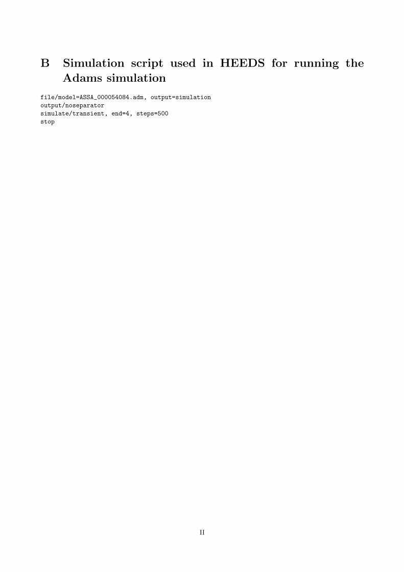
B Simulation script used in HEEDS for running the
Adams simulation
file/model=ASSA_000054084.adm, output=simulation
output/noseparator
simulate/transient, end=4, steps=500
stop
II
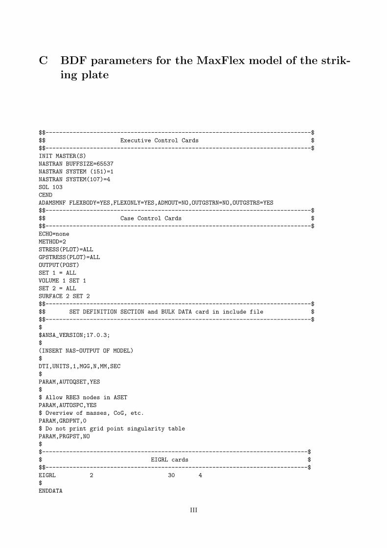
C BDF parameters for the MaxFlex model of the strik-
ing plate
$$------------------------------------------------------------------------------$
$$ Executive Control Cards $
$$------------------------------------------------------------------------------$
INIT MASTER(S)
NASTRAN BUFFSIZE=65537
NASTRAN SYSTEM (151)=1
NASTRAN SYSTEM(107)=4
SOL 103
CEND
ADAMSMNF FLEXBODY=YES,FLEXONLY=YES,ADMOUT=NO,OUTGSTRN=NO,OUTGSTRS=YES
$$------------------------------------------------------------------------------$
$$ Case Control Cards $
$$------------------------------------------------------------------------------$
ECHO=none
METHOD=2
STRESS(PLOT)=ALL
GPSTRESS(PLOT)=ALL
OUTPUT(POST)
SET 1 = ALL
VOLUME 1 SET 1
SET 2 = ALL
SURFACE 2 SET 2
$$------------------------------------------------------------------------------$
$$ SET DEFINITION SECTION and BULK DATA card in include file $
$$------------------------------------------------------------------------------$
$
$ANSA_VERSION;17.0.3;
$
(INSERT NAS-OUTPUT OF MODEL)
$
DTI,UNITS,1,MGG,N,MM,SEC
$
PARAM,AUTOQSET,YES
$
$ Allow RBE3 nodes in ASET
PARAM,AUTOSPC,YES
$ Overview of masses, CoG, etc.
PARAM,GRDPNT,0
$ Do not print grid point singularity table
PARAM,PRGPST,NO
$
$------------------------------------------------------------------------------$
$ EIGRL cards $
$$-----------------------------------------------------------------------------$
EIGRL 2 30 4
$
ENDDATA
III
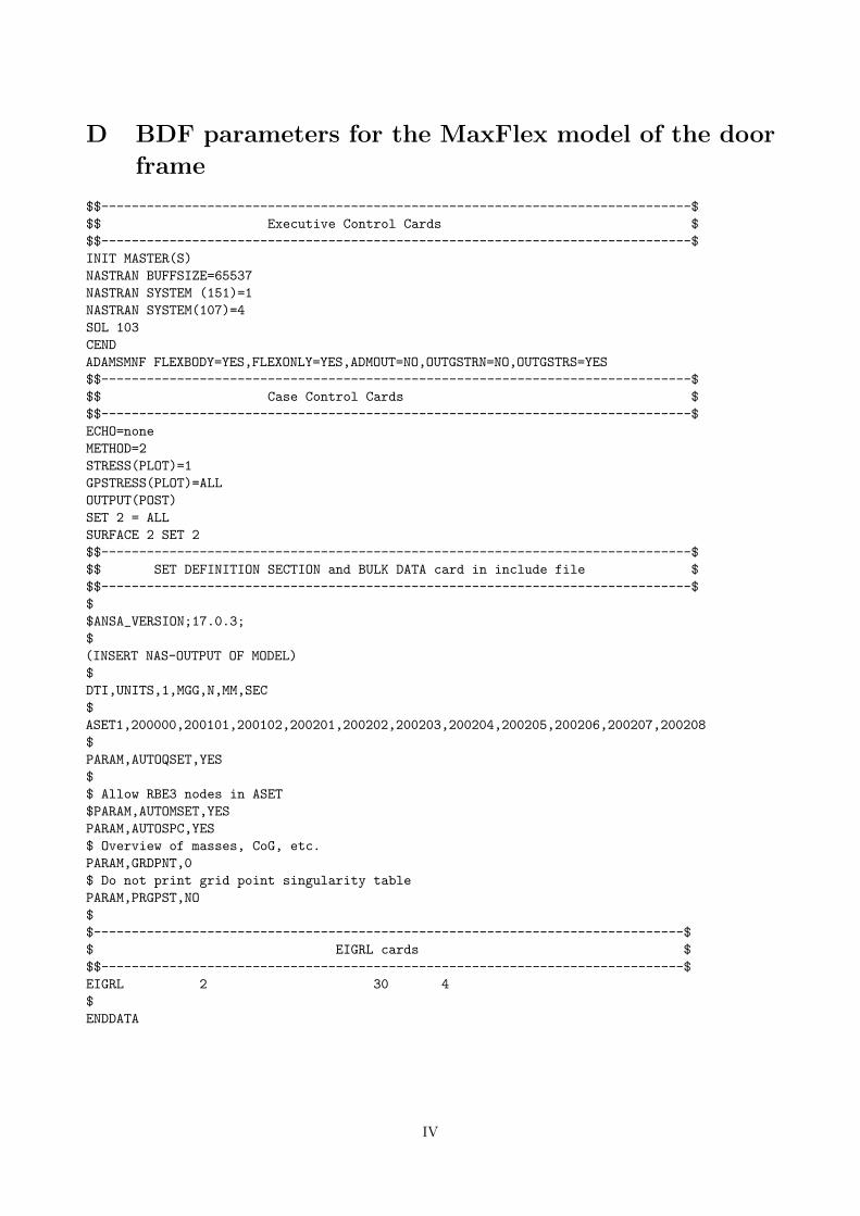
D BDF parameters for the MaxFlex model of the door
frame
$$------------------------------------------------------------------------------$
$$ Executive Control Cards $
$$------------------------------------------------------------------------------$
INIT MASTER(S)
NASTRAN BUFFSIZE=65537
NASTRAN SYSTEM (151)=1
NASTRAN SYSTEM(107)=4
SOL 103
CEND
ADAMSMNF FLEXBODY=YES,FLEXONLY=YES,ADMOUT=NO,OUTGSTRN=NO,OUTGSTRS=YES
$$------------------------------------------------------------------------------$
$$ Case Control Cards $
$$------------------------------------------------------------------------------$
ECHO=none
METHOD=2
STRESS(PLOT)=1
GPSTRESS(PLOT)=ALL
OUTPUT(POST)
SET 2 = ALL
SURFACE 2 SET 2
$$------------------------------------------------------------------------------$
$$ SET DEFINITION SECTION and BULK DATA card in include file $
$$------------------------------------------------------------------------------$
$
$ANSA_VERSION;17.0.3;
$
(INSERT NAS-OUTPUT OF MODEL)
$
DTI,UNITS,1,MGG,N,MM,SEC
$
ASET1,200000,200101,200102,200201,200202,200203,200204,200205,200206,200207,200208
$
PARAM,AUTOQSET,YES
$
$ Allow RBE3 nodes in ASET
$PARAM,AUTOMSET,YES
PARAM,AUTOSPC,YES
$ Overview of masses, CoG, etc.
PARAM,GRDPNT,0
$ Do not print grid point singularity table
PARAM,PRGPST,NO
$
$------------------------------------------------------------------------------$
$ EIGRL cards $
$$-----------------------------------------------------------------------------$
EIGRL 2 30 4
$
ENDDATA
IV