modelling of bridge pier afflux in 2d bill syme / phillip ryan
TRANSCRIPT

Modelling of Bridge Pier Afflux in 2D
Bill Syme / Phillip Ryan

Presentation Overview
Modelling of Bridge Afflux
• Why is it important
• Common Methods used
Test Model
• Numerical Engines Used
• Model Configuration
Findings
• Recommendations
• Conclusions

Presentation Overview
Why is modelling of bridges important
• Can be key in controlling flood behaviour
• A range of different methods used in practice
• No specific guidelines for 2D modelling
Focus of this presentation on the afflux caused by the bridge piers
• Do different methods/schemes produce consistent results?
• Are results affected by
• Model resolution
• Cell alignment
• Viscosity
• Other parameters

Test Case Model
Simple Test Case Model
• 1000m x 100m rectangular channel
• Manning’s n value of 0.025
• Fixed tailwater
• Inflow ramped up over 15minutes to 300m3/s and held steady for 45min
• 2 piers, each 5m wide x 20m long, with rounded ends

NUMERICAL ENGINES USED
TUFLOW “Classic”
• Grid based (square cells)
• Finite Difference Scheme
• Alternating Direction Implicit
TUFLOW GPU
• Grid based (square cells)
• 1st Order Finite Volume
• Explicit
TUFLOW FV
• Flexible mesh (quads and triangles)
• 1st and 2nd Order Finite Volume
• Explicit

Modelling Method
Block Cells Out
Elements are turned off, or raised to become dry
Pros
• Provides realistic velocities distribution
Cons
• Requires a high resolution mesh to resolve

Modelling Method
Form (Energy) Loss Coefficient (FLC)
Form Loss Coefficient (FLC)
• Energy loss based on fraction of V2/2g
Hydraulics of Bridge and Waterways (Bradley, 1978; AUSTROADS)
• J = 10m (pier width) / 100m (flow width)
• Kp = 0.2
• Whole waterway value for bridge
• V = 1.6m/s, afflux should be ~26mm

Modelling Method
Waterway FLC + Cell Width Reduction
FLC (as per previous method)
Cell width reduction applied
• 10% flow width reduction
• Applied equally to all cells across
• Reduction in flow width, gives increased velocity and therefore greater losses

Modelling Method
FLC Only on Pier Cells
FLC only applied to pier cells
For pier only FLC factor up whole waterway FLC
• Waterway FLC = 0.2, but only applied over 2x10m width (based on a 10m cell resolution)
• Pier Only FLC = 0.2 x 100m/20m = 1.0
(used same FLC and width of cells for finer grids for simplicity)
Improved water level contours

Modelling Method
Pier Only FLC + Cell Width Reduction
Pier Only FLC (as per previous)
Cell width reduction applied over the same cells
• reduced by 0.5 (5m pier width / 10m application width)

Preliminary Results(Still need to QA review results)
Afflux in mm (50m upstream)CPU
GPU
FV 1st Order
10.0m 5.0m 2.5m 1.0m 0.5m 0.25m
Block Cells Out 71
196
98
28
83
39
20
46
37
17
28
30
15
22
26
na
20
na
Waterway FLC26
26
25
26
25
25
26
25
25
26
25
25
26
25
25
na
25
na
Waterway FLC + Cell Width
Reduction
30
41
30
29
36
30
28
35
30
28
34
30
28
34
30
na
34
na
Pier Only FLC24
19
17
20
18
17
20
18
18
20
18
18
20
18
19
na
18
na
Pier Only FLC + Cell Width Reduction28
45
35
25
36
36
26
40
37
26
45
38
26
48
40
na
58
na
Observations
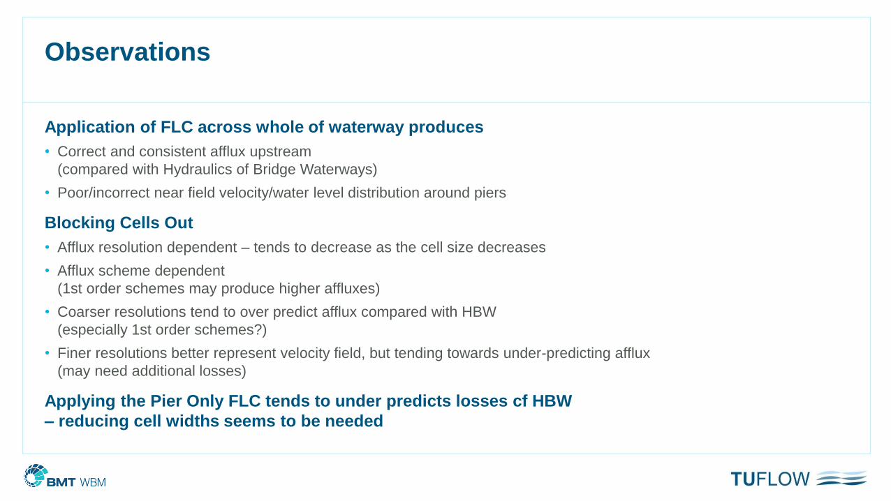
Application of FLC across whole of waterway produces
• Correct and consistent afflux upstream
(compared with Hydraulics of Bridge Waterways)
• Poor/incorrect near field velocity/water level distribution around piers
Blocking Cells Out
• Afflux resolution dependent – tends to decrease as the cell size decreases
• Afflux scheme dependent
(1st order schemes may produce higher affluxes)
• Coarser resolutions tend to over predict afflux compared with HBW
(especially 1st order schemes?)
• Finer resolutions better represent velocity field, but tending towards under-predicting afflux
(may need additional losses)
Applying the Pier Only FLC tends to under predicts losses cf HBW
– reducing cell widths seems to be needed

Other Considerations
Cell alignment
• With fixed grid, very hard to align to all bridges in a model!
• This is much easier in a flexible mesh (results not ready as yet)
Influence of Viscosity
• Method (Constant / Smagorinsky)
• Viscosity parameters
Bridge pier shapes
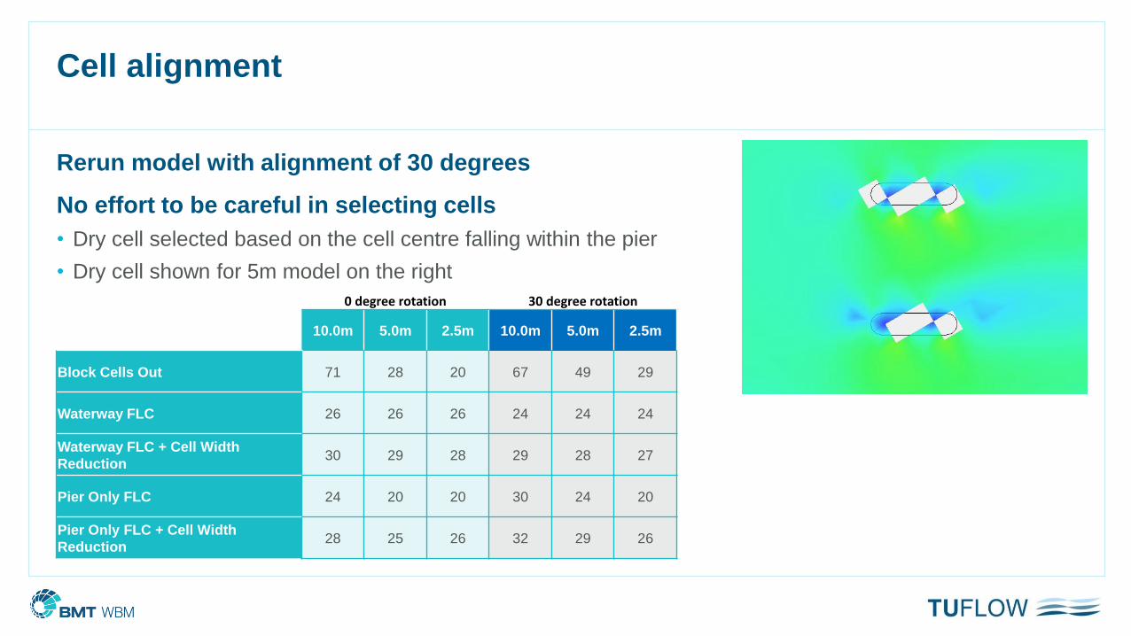
Cell alignment
Rerun model with alignment of 30 degrees
No effort to be careful in selecting cells
• Dry cell selected based on the cell centre falling within the pier
• Dry cell shown for 5m model on the right
0 degree rotation 30 degree rotation
10.0m 5.0m 2.5m 10.0m 5.0m 2.5m
Block Cells Out 71 28 20 67 49 29
Waterway FLC 26 26 26 24 24 24
Waterway FLC + Cell Width
Reduction30 29 28 29 28 27
Pier Only FLC 24 20 20 30 24 20
Pier Only FLC + Cell Width
Reduction28 25 26 32 29 26
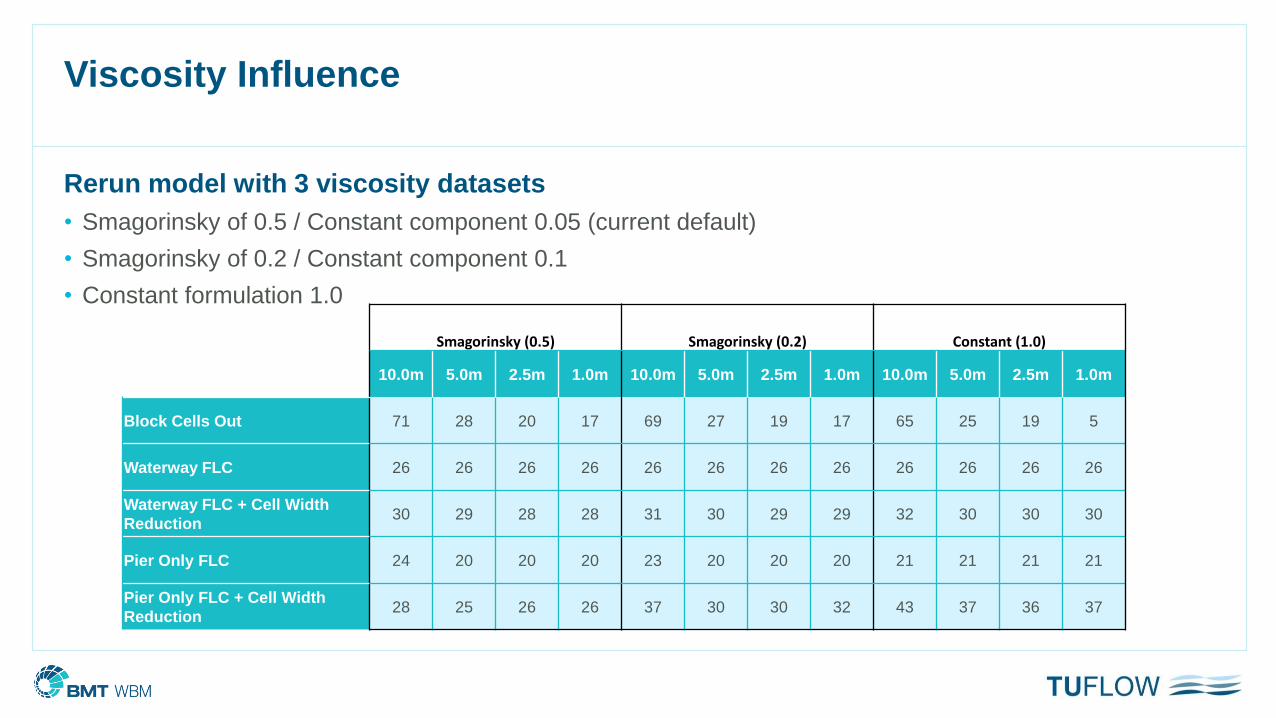
Viscosity Influence
Rerun model with 3 viscosity datasets
• Smagorinsky of 0.5 / Constant component 0.05 (current default)
• Smagorinsky of 0.2 / Constant component 0.1
• Constant formulation 1.0
Smagorinsky (0.5) Smagorinsky (0.2) Constant (1.0)
10.0m 5.0m 2.5m 1.0m 10.0m 5.0m 2.5m 1.0m 10.0m 5.0m 2.5m 1.0m
Block Cells Out 71 28 20 17 69 27 19 17 65 25 19 5
Waterway FLC 26 26 26 26 26 26 26 26 26 26 26 26
Waterway FLC + Cell Width
Reduction30 29 28 28 31 30 29 29 32 30 30 30
Pier Only FLC 24 20 20 20 23 20 20 20 21 21 21 21
Pier Only FLC + Cell Width
Reduction28 25 26 26 37 30 30 32 43 37 36 37
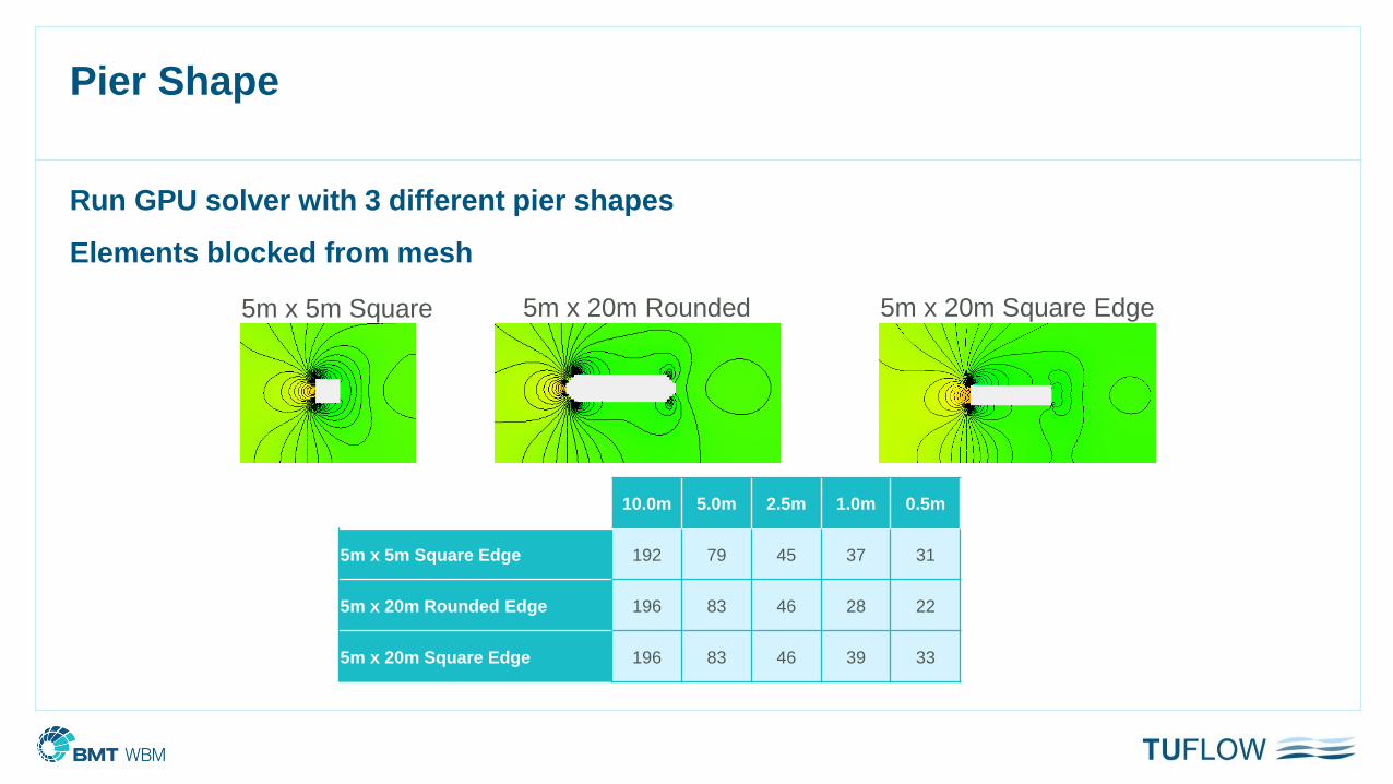
Pier Shape
Run GPU solver with 3 different pier shapes
Elements blocked from mesh
10.0m 5.0m 2.5m 1.0m 0.5m
5m x 5m Square Edge 192 79 45 37 31
5m x 20m Rounded Edge 196 83 46 28 22
5m x 20m Square Edge 196 83 46 39 33
5m x 5m Square 5m x 20m Rounded 5m x 20m Square Edge

Findings
Based on the comparisons of the preliminary model simulations
(>700 simulations thus far!)
Waterway or Pier Only FLC is the recommended approach
Provides consistent head loss (cf HBW) with variations in
• Cell size
• Cell Alignment
• Numerical schemes
• Viscosity
For complex 3D flow problems check your model results
with other methods/literature
CFD or Physical modelling may be required for complex pier arrangements

Further Research
Analyse other pier configurations
Compare a wider range of schemes/methods
• 1D / 2D methods
• Flexible meshes
Provide benchmark tests / provide guidelines
Haven’t even discussed what happens when the bridge deck surcharges!

thank you