modelling of manufacturing activities - … cus, dukovski, kuzinovski: modelling of manufacturing...
TRANSCRIPT

Int. j. simul. model. 5 (2006) 2, 69-81 ISSN 1726-4529 Original scientific paper
MODELLING OF MANUFACTURING ACTIVITIES BY
PROCESS PLANNING KNOWLEDGE REPRESENTATION
Gecevska, V.*; Cus, F.**; Dukovski, V.* & Kuzinovski, M.*
* Faculty of Mechanical Engineering, University Ss. Cyril and Methodius, Karpos II bb, PO Box 464, 1000 Skopje, Macedonia
** Faculty of Mechanical Engineering, University of Maribor, Smetanova 17, 2000 Maribor, Slovenia E-Mail: [email protected]
Abstract Process planning is one of the key activities for product design and manufacturing. Impact of process plans on all phases of product design and manufacture requires high level of interaction of different activities and tight integration of them into coherent system. In this paper we describe a model for manufacturing activities that allows integration. The framework for integration is briefly described and the manufacturing process model that considers three dimensions of planning is explained. Than an object-oriented knowledge representation approach is presented with module for parts modeling and module for generation of process plan. Description of machining process entities and their relationships with features, machines and tools are provided. The benefits of the proposed representation, which include connection with geometric model, reduced search space and alternative plan generation, are discussed. These new contributions provide for a new generation of CAPP systems that can be adapted for various manufacturing systems and can be integrated with other CIM modules. (Received in October 2005, accepted in February 2006. This paper was with the authors 2 months for 2 revisions.) Key Words: Process Planning, Knowledge, Object-Oriented Programming, Features 1. INTRODUCTION In today manufacturing environment, many large industries attempted to introduce flexible manufacturing systems (FMS) as their strategy to adapt to the changing competitive market requirements. To ensure the quality of machining products, to reduce the machining costs and to increase the machining effectiveness, it is very important to select machining parameters for CNC machining.
Computer Integrated Manufacturing development has focused for a long period of time in linking various automated activities within the enterprise. However, the complexity of manufacturing process itself and extended application of computer supported equipment has led toward identifying three mail phases in manufacturing integration [2, 5]: (1) hardware and software integration, (2) application integration and (3) process and people integration. After several years in focusing on CAD/CAM integration, the research has moved toward the third phase, process integration. One of most important links for implementation of integrated manufacturing is process planning, the link between product design (CAD) and production planning and execution (CAM, MES). Process planning as one of the key activities for product design and manufacturing is developed in many research. There are numerous papers devoted to various process planning systems which achieve certain level of manufacturing planning integration. Early major CAD/CAPP integration works are [2], [3] that provide the integration between CAD and CAPP systems and provide the actual machining on NC machine connected to the system. Recent research efforts are devoted to generation and
DOI:10.2507/IJSIMM05(2)3.062 69

Gecevska, Cus, Dukovski, Kuzinovski: Modelling of Manufacturing Activities by Process ...
evaluation of alternative process plans and to enlargement of manufacturing knowledge base [1, 2, 4]. Integration with other manufacturing planning functions and the issues of data and knowledge representation and integration framework has also received significant interest [5].
This paper addresses an issue of generating process information within the integration framework in order to modeling manufacturing systems. The paper is organized in two sections. The first section describes interactions between manufacturing planning functions and identifies the need for integration. The second section explains manufacturing process’ model and its modeling by object-oriented programming approach, developed in our research. 2. MANUFACTURING SYSTEM ACTIVITIES INTERACTION The product development and manufacture involves several production management activities with a series of individual tasks that are to be completed in order to design and manufacture a product of a required quality. These tasks are usually carried out in a linear sequence, but very often the feedback is necessary from the subsequent task to the previous one. Many of these feedback loops are requests to modify the previous task’s solution in order to generate a better solution in the subsequent one. This interlinking is what has become known as concurrent or simultaneous engineering.
This section of paper will provide a model of manufacturing activities and tasks, and identify how these tasks connect high level activities. It is done identified need for integration from the whole cycle of product development and described of manufacturing activities model with extensive set of manufacturing planning tasks.
2.1 Need for integration
Product development cycle may be seen as a set of answers to a series of actually simple questions [3, 4]: Why to produce? What to produce? How to produce? Where to produce? Who to produce? When to produce? The answers of these questions will identify what functions a necessary in the cycle from developing an idea to the realization of the final product. Answers to these questions may be given by connecting them with particular manufacturing functions (Fig. 1): marketing function, design function, process planning function, resource planning function, production control function. The figure shows that product development cycle is not a linear path without obstacles. Usually, the product development follows some zigzag pattern between functions with frequent needs to feedback information from a function to previous one. There are numerous feedback loops and overlapping between functions. Therefore, there are production planning tasks that can not easily be classified into particular functions and these tasks lead toward integration between these functions. IDEA PRODUCT
WHY?
Marketing
HOW? Process Planning
WHEN? Production
control
WHAT? Design
WHERE? Recsurce Planning
Figure 1: Basic product development cycle planning functions.
70

Gecevska, Cus, Dukovski, Kuzinovski: Modelling of Manufacturing Activities by Process ...
2.2 Manufacturing activities model
Starting from analyzing set of tasks of process planning and other activities, it is possible to develop the model that shows interactions between process planning and them. The model of these interactions is shown in Figure 2, where each activity represents with circle, consists a set of tasks that are to be done in the product development. All of these activities are identified in manufacturing planning literature as activities required during the product development and manufacture. The classification shown in the Figure 2 represents a starting point for the use of this method in each individual factory. There are numerous tasks that require interactions between two or more activities. They are shown within overlapping circles of activities and represent integration links.
Feature based design Geometry based design
Solid modeling
Stock definition Material selection
Manufacturing strategy
Process selection Operation sequencing
Part orientation
Setup planning NC programming
Shop floor plan release
Feature modeling
Tolerance relations Feature constraints Feature alternatives
Feature extraction Feature accessibility Feature interactions
Job sequencing
Shop floor order release
Shop floor capacity verification
Capacity planning
Production planning Master production
schedule MRP I, MRP II
Manufacturing knowledge
base
Layout planning Cell design
Cost evaluation MRP adjustment
Figure 2: Product development tasks. For example, setup planning is part of process planning, but also needs information about
scheduling for efficient setups, or feature modeling belongs between design, future recognition and process planning. Another example is in interaction of design and process planning functions. One of task in the product development is stock selection (material and shape), as a part of product design. By definition the part material we may reduce alternative manufacturing processes, for example by selecting cast iron as material, we decide that casting process is required and later machining processes involve only needed finishing of small number of part faces. In another case, if we define a sheet metal as stock shape, some pressing or deforming operations are necessary.
It is important to understand explained interactions shown on the Fig. 2 in order to completely utilize engineering knowledge and expertise. Each of these activities needs specialists in the domain, while intersections need group work and they are suitable for applying concurrent engineering principles. The most important intersections from process planning perspective are: between design and process planning related to part family formation, between process planning and resource management related to manufacturing cell design and between process planning and scheduling related to production control of cells.
71

Gecevska, Cus, Dukovski, Kuzinovski: Modelling of Manufacturing Activities by Process ...
3. MODELING OF MANUFACTURING PROCESS In this section, it is describe the manufacturing process model, for representing planning functions and tasks for manufacturing processes and it is explained the model dimensions: variety, time and aggregation. 3.1 Manufacturing process model dimensions The basic entity of the manufacturing process model is a process, understood as an activity, usually planned in advance, with all necessary attributes. All manufacturing planning functions generate various planned tasks or activities (e.g. cutting with turning cutter, deforming with a press, machining on a single machine, processing job order etc.). Each of these tasks has numerous attributes, that have to be defined before the task can be undertaken (e.g. for cutting with turning cutter, it has to define part, tool, cutting parameters, space orientation of part and tool on a lathe, starting time, ending time etc.). These attributes are usually defined by different manufacturing planning functions.
In this section of paper it is identified the dimensions of manufacturing process model that are independent of planning function, require transfer from one function to another and facilitate manufacturing integration.
The manufacturing process model consists of three dimensions: time, variety and aggregation. Each manufacturing process is related to other processes with respect to these three dimensions. The time dimension describes relative temporal relation between several processes of the same type. This relation has several levels of certainty. The lowest level is when we specify that some process has to be machined before or after another (e.g. the hole has to be drilled after the surface has been milled, if that surface was cast earlier).
The variety dimension describes sets of different processes that are generated within a certain level. Usually it is necessary to define a set of different processes in order to complete the manufacturing task. For example, when it defines the process plan for a given part, there is a set of features that require a set of cutting processes. Also, one feature may require more that one process, for example, a hole may require drilling and reaming. Another way for generation of different processes is generation of alternatives. For example, in selection of cutting processes, there are usually several alternative cutting methods to machine the same feature, a slot may be machined by end milling or side milling, and so on.
The aggregation dimension relates to various scopes of planned processes. Processes are defined with different levels of details, time frame-duration. Also, usually a set of manufacturing processes, planned in one function, may be considered as a whole in another planning function. For example, in process selection the cutting process for each feature is considered separately, in setup planning these processes are combined for the same machine, while in scheduling the whole process plan for the part is considered as a unit. Therefore, this dimension explains that some process is a part of another process with the same part, machine, tool or some other attribute. This is necessary in order to distribute planning tasks among different functions. In the above examples, different levels of aggregation allow different planning tasks (process selection, setup planning, scheduling) to focus only on attributes relevant for the task.
Three explained dimensions are not independent. The relations that hold between processes in one dimension impact other dimensions as well. For example, scheduling and machine load constraints may have an impact on process plans in terms of selecting an alternative plan which may balance the machine load.
72

Gecevska, Cus, Dukovski, Kuzinovski: Modelling of Manufacturing Activities by Process ...
Overall manufacturing planning activity creates such a model in a distributed fashion i.e. several specialists with different knowledge are involved, and the model is subject to change as manufacturing planning and execution progresses.
3.2 Process planning network
The basis of the above-described modeling of manufacturing process is the process planning network. This network is result of process planning that enable manufacturing integration. The process planning network consists of four interconnected layers: feature layer, process layer, tool orientation layer and machine layer. The first layer, feature layer, represents a network of machining features. The next layer is the process layer, which contains process candidate instances for individual features. In this layer it is necessary to show alternative machining processes for the same features in order to allow for later selection of the most suitable processes for given conditions. The next layer is tool condition layer that nodes represent sets of cutting process instances performed using tool orientation and machine type. The final layer of process planning network is machine layer. Its nodes set of cutting processes but with all constraints of machining conditions in order to determine - cutting data. 4. DEVELOPMENT OF A SYSTEM FOR PROCESS PLANNING
The process planning with several incorporated procedures described in this paper is part of a largest CAPP decision support system called OPTICAPP (Optimized Computer Aided Process Planning), the general layout of which is shown in Fig. 3.
The OPTICAPP system is implemented under the Microsoft Windows environment using the object-oriented programming with C++ program language. This system is structured with two basic program’s module. Using a theory of graphs, mathematical logic and semantics, production rules and procedures are defined. Their structure is based on the interaction between technological orders of the machining (construction of workpiece, ordering of machining operations - mulltipass machining operations where one pass presented the sub-operation (rough or finish pass, or one cutting tool pass), priorities of the cutting operations, selection of tools, generation of optimal cutting data etc.). The optimization is made by a set of technological constraints, which include tool life, surface finish, machine power and available spindle speeds and feeds.
4.1 Module of parametric modelling designer The first module is computer aided designer, named GRAPH (Graphic Modeller). This module is used for work-parts modelling, based of features geometry recognition generated interactively by the operator, using a simple icon-based interface. The GRAPH modeller is based of a parametric method of modelling using developed icon based interface, showed on the Fig. 4. Each icon represent one feature as an elementary work-part geometrical form. It is geometrical defined more than thrty different features, described with specific geometrical parameters (atributs). During modeling of one work-part it is nececery to sellecting and definition of several features in according to the construction model of the work-part. During definition of geometrical parameters for each selected feature, this program module needs from user to define the technological parameters, as a work-part material, surface rughness, tolerances.
73

Gecevska, Cus, Dukovski, Kuzinovski: Modelling of Manufacturing Activities by Process ...
Figure 3: Overal layout of OPTICAPP.
74

Gecevska, Cus, Dukovski, Kuzinovski: Modelling of Manufacturing Activities by Process ...
Figure 4: Developed icon based interface in GRAPH modeller.
This module is based of the original developed mathematical methodology for modelling
of mechanical part as a complex structure of features based of theory of graph, mathematical logic and semantics. The main characteristic of this module is the fact that, as a output, a dinamic model of the mechanical part is generated. The GRAPH modeller, for each modelled part, develops original dynamic database as a Duble Linced List (DLL), core of the algorithm, holder of all geometrical and technological data for part. Dynamic database is based on the oriented multygraphs and data linking with pointers in DLL (Fig. 5). Dinamic database for each modeled mechanical part is declared with follow program structure (struct rot type):
struct rot type { int Prim; char *data; float Data [MAXNUMPAR+1]; struct rot_type *prior; struct rot_type *next; } * first, *last, *cur_rec;
Figure 5: Duble Linced List (DLL) with grafical presentation of pointers (next and prior).
It is database for sorting and storing data for modelled mechanical part. Sorting of data in
dinamic database is with network of knots and pointers (Fig. 6), holder of data for all features in part’s model. The main advantage of this parametric modelling based design module is possibility for dynamical change of the created work-part model within the sellected features. Softwere inter-comunication is based of the complex part model (DLL with annexed oriented vectors) and many algorithms and procedures, as: algorithm for search and algorithm for subordination, here done with original code:
75

Gecevska, Cus, Dukovski, Kuzinovski: Modelling of Manufacturing Activities by Process ...
Algorithm for search: Algorithm for subordination:
info = from; if (way) { while (info) { num = (info->Prim); if ( (key==(info->Data[0])) && caracter(num)=what ) return info; info = info->next; } else { while (info) { num = (info->Prim); if ( (key==(info->Data[0])) && caracter(num)=what ) return info; info = info->prior; }
void left_face I ( void ) { struct rot_type *info, *temp; i=1; tem = info = first; Xorg=(MaxX+1)/40 ; Yorg=MaxY/2; while ( info ) { info = find (temp, 1, CELEN); section I ( info, i, -1); from left to right temp = info->next; if (!info) break; i++; } return; }
Figure 6: Dinamic database with network of knots and pointers. On the Fig. 7, it is presented step by step (on going) modeling of mechanical part using
features in GRAPH modeller.
Cancel
a) Step of including cilinder feature with accessory window for parameters on-line assigning
76

Gecevska, Cus, Dukovski, Kuzinovski: Modelling of Manufacturing Activities by Process ...
Cancel
b) Step of including slot feature with accessory window for parameters on-line assigning
c) Step of parametric on-line changing parameter (diameter) for previous included feature Figure 7 (a, b, c): Modeling of mechanical part using features in GRAPH modeller.
77

Gecevska, Cus, Dukovski, Kuzinovski: Modelling of Manufacturing Activities by Process ...
4.2 Module for generating process plan network The second module, it is generated process plan network for machining of modelled work-part by using the GRAPH modeller, module of OPTICAPP system. This module is named CAP-Plan (Computer Aided Process Plan). In this research, it is programming object-oriented algorithm using C++, based on a generative method with intelligent approach, as an expert system shell. This algorithm constitutes mathematical methodology with many developed rules and procedures for modelling of process planning. This algorithm can perform the following functions:
• Creating technological knowledge database for modelled mechanical part using the data from designer module,
• Presenting the technological knowledge with created rules for decision making,
• Algorithm for modelling process plan network for production with selection and succession on the operations and sub-operations,
• Modelling of each operation with order of sub-operation and optimized cutting parameters for each sub-operation,
• Select of cutting tools and machines for complete manufacturing process, • Output presentation of generated process plan network.
a) Characteristics of the object-oriented modelling of process planning Decision for created a module for object-oriented modelling of process planning approach for automatic ordering of operations and sub-operation in machining process, it is based of the following reasons: generative approach of modelling as a method for individual design and modelling, recognition and process planning for each created mechanical part, open possibility for connection and integration of developed system in complex integrated CAD/CAPP/CAM system. The module for process planning CAP-Plan, as inputs, uses:
• The dynamical database oriented model of the mechanical part generated in graphic modeller-GRAPH.
• The technological database of the model, carrier of a technological knowledge for modelled part necessary for process planning / generated in this program’s module in the research/.
b) Technological knowledge database Technological knowledge, as a basic for process planning, is composed of data and information, which is spectrum of know-how (Fig. 8). Generally, the technological knowledge can be to divide on:
Basic technological knowledge Experienced technological knowledge
Basic technological knowledge is accumulated in literature and technological atlas books, as a principle on tabular or described form. Experienced knowledge in the literature is known as “know-how”. This knowledge is composed with experience and it is accumulated by the engineers during the years, but it’s almost impossible to attend this methodology in order to be formalise concrete and in whole.
78

Gecevska, Cus, Dukovski, Kuzinovski: Modelling of Manufacturing Activities by Process ...
Figure 8: Logical structure of technological knowledge database. c) Mathematical methodology for technological plan design Mathematical methodology for process planning and developing of technological plan is made with many algorithms and production's rules. The most suitable form for presentation of the technological knowledge is the form of modular production’s rules, where each rule determines environs technological statement and it is free from other rule. Technological knowledge has been structured with the help of four types of the production’s rules. With object-oriented programming in the module for process planning, there are created following algorithms, which comprise logic for decision for each component of the process planning:
The algorithm for define dimension on starting work part, The algorithm for design the form and the succession of the technological operation, The algorithm for modelling the actions into each operation (multi-pass operation), The algorithm for modelling the optimizing trajectory of cutting tool movement
between the position points of machining. The algorithm for evaluation of justification for machining with one tool in all
positions where it is predicted, or changing tool in certain position.
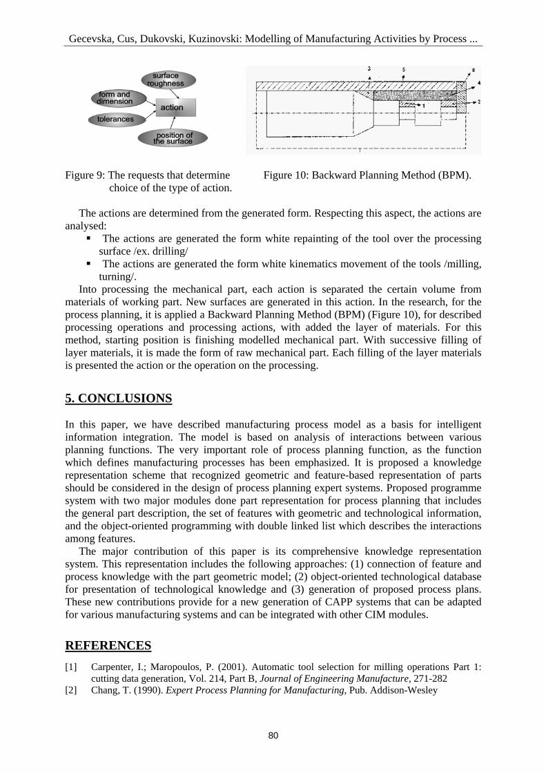
In the research, proposed OPTICAPP system, near two main modules for modelling and process planning, consists sub-module for optimization of cutting parameters for each machining operation and action, designed in process planning. It is developed as a multi-objective programming mathematical model where the optimal solution is obtained by using a deterministic method and a genetic algorithm, described in [8]. The cutting data optimization criterion is selected from minimum machining time or cost, maximum production rate. d) Modelling the action as part of technological operation The sub-operation, called action, is generated a surface on the mechanical part. For each surfaces a mechanical part, it is necessary projecting an action in the chosen operations. The requests that determine choice of the types of actions are the form, the dimension, the surface roughness, and the tolerances of the dimension and the position (Fig. 9).
79
Gecevska, Cus, Dukovski, Kuzinovski: Modelling of Manufacturing Activities by Process ...
Figure 9: The requests that determine Figure 10: Backward Planning Method (BPM). choice of the type of action. The actions are determined from the generated form. Respecting this aspect, the actions are analysed:
The actions are generated the form white repainting of the tool over the processing surface /ex. drilling/
The actions are generated the form white kinematics movement of the tools /milling, turning/.
Into processing the mechanical part, each action is separated the certain volume from materials of working part. New surfaces are generated in this action. In the research, for the process planning, it is applied a Backward Planning Method (BPM) (Figure 10), for described processing operations and processing actions, with added the layer of materials. For this method, starting position is finishing modelled mechanical part. With successive filling of layer materials, it is made the form of raw mechanical part. Each filling of the layer materials is presented the action or the operation on the processing. 5. CONCLUSIONS In this paper, we have described manufacturing process model as a basis for intelligent information integration. The model is based on analysis of interactions between various planning functions. The very important role of process planning function, as the function which defines manufacturing processes has been emphasized. It is proposed a knowledge representation scheme that recognized geometric and feature-based representation of parts should be considered in the design of process planning expert systems. Proposed programme system with two major modules done part representation for process planning that includes the general part description, the set of features with geometric and technological information, and the object-oriented programming with double linked list which describes the interactions among features.
The major contribution of this paper is its comprehensive knowledge representation system. This representation includes the following approaches: (1) connection of feature and process knowledge with the part geometric model; (2) object-oriented technological database for presentation of technological knowledge and (3) generation of proposed process plans. These new contributions provide for a new generation of CAPP systems that can be adapted for various manufacturing systems and can be integrated with other CIM modules. REFERENCES [1] Carpenter, I.; Maropoulos, P. (2001). Automatic tool selection for milling operations Part 1:
cutting data generation, Vol. 214, Part B, Journal of Engineering Manufacture, 271-282 [2] Chang, T. (1990). Expert Process Planning for Manufacturing, Pub. Addison-Wesley
80

Gecevska, Cus, Dukovski, Kuzinovski: Modelling of Manufacturing Activities by Process ...
[3] Balic, J.; Pahole, I. (2003). Optimisation of intelligent FMS using the data flow matrix method, Journal of Materials Processing Technology, Vol. 133, No. 1/2, 13-20
[4] Sormaz, D. (1999). Intelligent Manufacturing Based on Generation of Alternative Process Plans, Proceedings of 9th Int. Conference on Flexible Automation and Intelligent Manufacturing, Tilburg, 35-49
[5] Buchmeister, B.; Kremljak, Z.; Pandza, K.; Polajnar A. (2004). Simulation Study on the Performance Analysis of Various Sequencing Rules, International Journal of Simulation Modelling, Vol. 3, No. 2-3, 80-89
[6] Singh, P. K.; Jain, S. C.; Jain, P. K. (2004). Concurrent Tolerance Desidn with Alternative Manufacturing Processes, International Journal of Simulation Modelling, Vol. 3, No. 1, 5-16
[7] Koza, J. R. (1994). Genetic Programming II, The MIT Press, Massachusetts, USA [8] Gecevska, V.; Cus, F.; Kuzinovski, M.; Zuperl, U. (2005). Evolutionary Computing with
Genetic Algorithm in Manufacturing Systems, Journal of Machine Engineering, Vol. 5, No. 3/4, 188-198
[9] Jain, A.; Jain, P.; Singh, P. (2005). Deadlock Analysis in FMS in the Presence of Flexible Process Plans, International Journal of Simulation Modelling, Vol. 4, No. 2, 53-66
[10] Browne, J.; Harnen, J.; Shivnan, J. (1997). Production Management Systems – An Integrated Perspective, Pub. Co. Addision-Wesley, Reading, MA, USA
[11] Milfelner, M.; Zuperl, U.; Cus, F. (2004). Optimisation of Cutting Parameters in High Speed Milling Process by GA, International Journal of Simulation Modelling, Vol. 3, No. 4, 121-131
[12] Lalic, B.; Cosic, I.; Anisic, Z. (2005). Simulation Based Design and Reconfiguration of Production Systems, International Journal of Simulation Modelling, Vol. 4, No. 4, 173-183
[13] Dereli T.; Filiz, H.; Baykasogly, A. (2001). Optimizing Cutting parameters in process planning of mechanical parts by using genetic algorithms, International Journal of Production Research, Vol. 39, No.15, 3303-3328
81