modelling the adsorption of fibrinogen and its changes of orientation due to surface chemistry
TRANSCRIPT

Modelling the Adsorption of Fibrinogen and its Changesof Orientation Due to Surface Chemistry
Elizabeth Mott
September 2016
Dissertation Submitted in Partial Fulfilment of the degree of MSc in programme title (year 1)
I warrant that the content of this dissertation is the direct result of my own work and thatany use made in it of published or unpublished material is fully and correctly referenced.
Abstract
The influence of a protein’s shape and chemistry, with respect to its adsorption ontoa surface, is presented. The case of the protein molecule, fibrinogen, binding to a hy-drophobic surface was modelled, as the shape of a fibrinogen molecule is an oblongshape rather than a spherical. The adsorption of a fibrinogen molecule binding to ahydrophobic surface occurs in two stages, because of its oblong shape. Fibrinogen hastwo orientations in which it can bind to a surface upon adsorption and rearrangementsof orientation can occur after the initial adsorption stage. The rate of initial adsorptionand orientation rearrangement has been defined by modified tanh functions dependenton the surface’s chemistry. It was found that the model gives rise to adsorption profilessimilar to those determined experimentally.
1 Introduction
Adsorption is the accumulation of molecules or particles onto a surface [7]. The adsorptionof protein molecules from blood to a bio-material’s surface is an important study in material,and medical science, where a bio-material is a synthetic material (usually a plastic) suitablefor implanting in a living body to repair damaged or diseased parts e.g. hip replacements[11].
The process of adsorption is a complicated one which depends upon a variety of factors. Thesize of the protein affects adsorption [4]. Smaller proteins can diffuse through solution morequickly; however, they have fewer contact points with the surface, so the strength of the ad-sorption is weaker [9]. The chemistry of the protein molecules, and the surface, has an influ-ence on the rate and strength of adsorption. Both the protein and the surface can be eitherhydrophobic or hydrophilic. A molecule is hydrophobic when it is repelled by water in a so-lution and a molecule is hydrophilic when it is attracted to water in a solution. Hydropho-bic protein molecules tend to bind more rapidly and form stronger bonds with a surface thatis hydrophobic, or charged. The strong attraction between a hydrophobic surface and a hy-drophobic protein is driven by the protein molecules being repelled by water to the surface.Both the protein and the surface is partly covered, and no longer in contact with as muchwater in the solution [5], due to the adsorption of the protein onto the surface. On the other
1

Figure 1: A diagram representing the different orientations by which fibrinogen can bind to asurface. Side-on orientation, S1 and end-on orientation, S2.
hand, hydrophilic proteins are not repelled by water in a solution so are less attracted to hy-drophobic surfaces. It is important to note that despite the nature of hydrophobic and hy-drophilic proteins stated above, a protein of either nature will still bind to surfaces with ahydrophobic or hydrophilic charge, just at different rates and binding strengths.
The adsorption of blood proteins to biomaterial surfaces is an area of active research [2],where fibrinogen and albumin are two known protein molecules studied in the blood. Albu-min is a globular, spherical, protein that helps regulate both the binding of blood with phar-maceuticals and the osmotic pressure of the blood [8]. Fibrinogen is a large oblong shapedprotein. Fibrinogen’s main role in the blood is to aid the formation of blood clots. Albuminand fibrinogen can adsorb onto both hydrophobic and hydrophilic surfaces; however, both arefound to interact more strongly with hydrophobic surfaces [8].
The adsorption of fibrinogen onto a hydrophobic surface is complicated, compared to albu-min. Fibrinogen binding appears to occur in steps, where the initial rate of adsorption israpid (50 seconds), whilst the second stage occurs over a longer period (60minutes) [8]. Fib-rinogen has two binding orientations due to its oblong shape. When a fibrinogen protein ad-sorbs onto a surface it can either bind with its long-axis perpendicular to the surface, whichis denoted the end-on orientation, or it can bind with its long-axis parallel to the surface, thisis denoted the side-on orientation. These orientations are shown in Figure 1. It has been sug-gested that fibrinogen initially adsorbs in the side-on orientation quickly, covering all the sur-face, then, after time, switches to the end-on orientation, uncovering binding sites and allow-ing additional fibrinogen molecules to bind [8]. This rearrangement is said to be due to thehydrophobic nature of fibrinogen, as the end-on orientations are attracted together so theyalign with each other for minimal surface exposure to the water in the solution[8]. This twostaged adsorption of fibrinogen has only been observed at high concentrations and onto hy-drophobic surfaces [8].
Protein-surface interactions have been previously modelled mathematically by [1], [3], [6] and[10] using the law of mass action, yielding governing ordinary differential equations (ODEs),which were then solved numerically.
The rates of two proteins adsorbing onto a surface have been compared by two different mod-els in [6], where the first model was based on a ‘single lumped kinetic parameter’ and thesecond model considered ‘the individual transport processes occurring prior to the adsorp-tion reaction’. In the case when the protein molecule albumin was modelled, it was concludedthat neither approach correctly predicted the adsorption profiles observed from experimentalresults. The poor fit using the kinetic rate constant model is suspected to be due to the com-petition between the albumin molecules and the lysozyme molecules in the solution, as the
2

Figure 2: The adsorption profile and the derivative plot (inset) of fibrinogen on hydrophobic(circle plot) and hydrophilic (triangle plot) terminated surfaces, reproduced, with permissionfrom; [8]. The two stages of adsorption can be seen more distinctively in the derivative, com-pared to the adsorption profile.
albumin molecules are much larger than the lysozymes, hindering the adsorption of albumin.
In [3], the adsorption process of a protein (FNIII7−10) was modelled with respect to its con-formational changes, where the protein’s bonds break down after adsorption, causing the pro-tein to spread out across the surface. The conformational changes of the protein (FNIII7−10)upon adsorption here was represented by parameter values for each of the molecule’s states,a1 and a2, where a1 denotes the area occupied by the molecules before a conformational changehas occurred, state 1, and a2 is the area occupied after the conformational changes have oc-curred, state 2. However, it was concluded that the conformational changes, by the use ofthe parameter values a1 and a2, did not truly reflect the conformational change of the pro-tein (FNIII7−10) when compared with experimental data. This is because the conformationchanges of a protein are governed by more than just the surface area occupied by a protein.
A study was also conducted in which two models were developed to investigate the adsorp-tion characteristics of proteins with different concentrations, surface affinities, sizes and areas[10]. It was concluded that the nature of proteins can be modelled using only information onthe protein’s concentration in a solution, its surface affinity and size.
The adsorption of fibrinogen molecules onto a surface can be modelled using a similar ap-proach to [1], [3], [6] and [10]. The adsorption process of fibrinogen has also been investigatedexperimentally [8], providing information that can aid in model formulation.
The information available on the adsorption of fibrinogen influenced the decision to model,and replicate, the experimental results published in [8], showing the adsorption profile of fib-rinogen onto a hydrophobic terminated surface. Since the shape of a molecule and the chem-istry between a molecule and a surface is of great interest to those studying the adsorptionof molecules onto a surface, a hydrophobic surface is chosen to be modelled as the chem-istry between fibrinogen molecules and a hydrophobic surface is what causes the change oforientation and produces a two staged adsorption profile for fibrinogen, as seen in Figure 2.Therefore, the models formulated in the remainder of this paper focus on the case of a singleprotein species, fibrinogen and take into account the different orientations of fibrinogen.
3

2 Model 1 formulation: constant reaction rates
Fibrinogen molecules adsorb onto a surface, binding to sites on the surface in either the side-on, S1, orientation or the end-on, S2, orientation, where the side-on orientation will take upmore surface area than those in the end-on orientation. Once the molecules have adsorbedonto the surface, they may flip between orientations. When a protein flips from the S1 to theS2 orientation it opens up free binding sites, S. Taking all this into account, the followingreactions must be modelled, where C is the amount of protein in the solution:
C + Sk+1
k−1S1 , (1)
C + Sk+2
k−2S2 , (2)
S1
k+3
k−3S2 + S. (3)
The binding rate of fibrinogen in the side-on (end-on) orientation is denoted as k+1 (k+2 ),whilst the rate of the unbinding is denoted as k−1 (k−2 ). The rate at which fibrinogen switchesorientation, from side-on to end-on (S1 to S2), is denoted by k+3 , and the rate at which fib-rinogen switches orientation from end-on to side-on (S2 to S1) is denoted by k−3 .
Applying the law of mass action to reactions (1)-(3), we derive the following pair of ODEs forthe surface concentration of side-on fibrinogen, s1(t), and end-on fibrinogen, s2(t), over time,t:
ds1dt
= V k+1 cs− s1k−1 − s1k
+3 + s2sk
−3 , (4)
ds2dt
= V k+2 cs− s2k−2 + s1k
+3 − s2sk
−3 , (5)
where c(t) is the concentration of protein in the solution, s(t) is the density of free bindingsites and V is the volume of the solution in which the fibrinogen proteins are suspended. Theinitial concentration of fibrinogen, c(0), and the initial density of free binding sites, s(0), areknown. The surface is free of any end-on or side-on orientated fibrinogen initially. Thereforethe following initial conditions can also be imposed:
s1(0) = s2(0) = 0, c(0) = c0, s(0) = sT , (6)
where c0 and sT are known constants. See Tables 1 and 2 for descriptions of the variable andparameters used in this model.
4
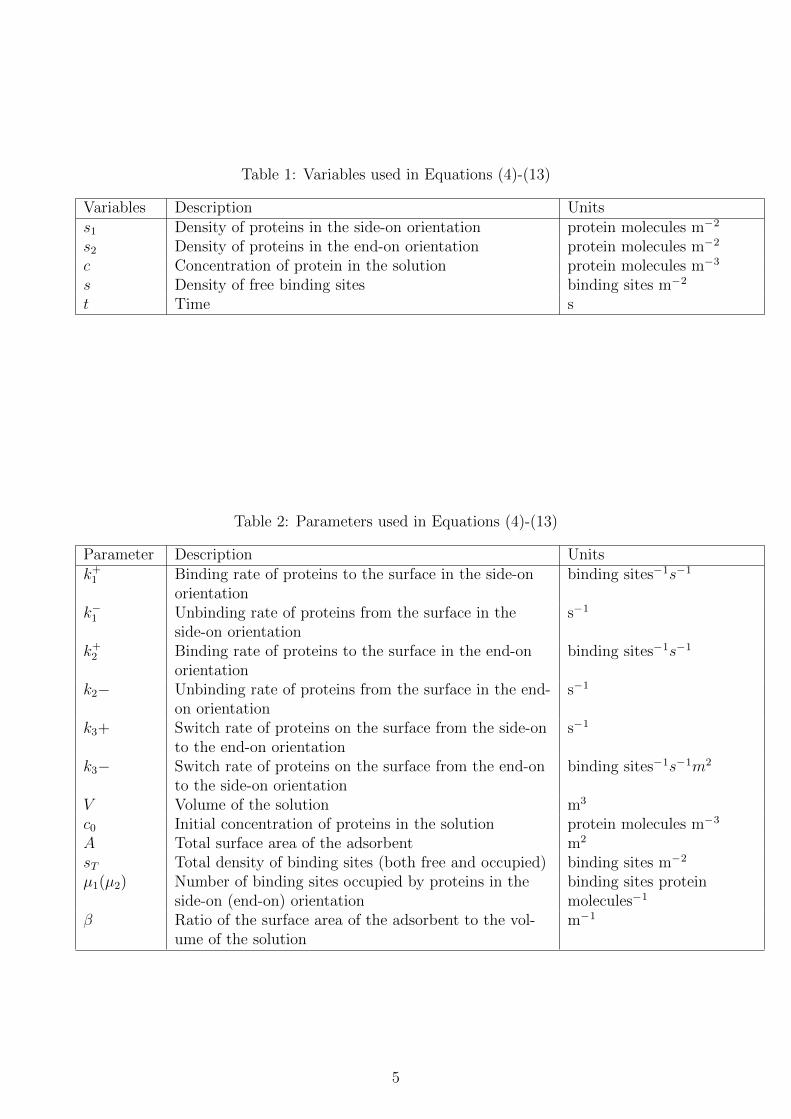
Table 1: Variables used in Equations (4)-(13)
Variables Description Unitss1 Density of proteins in the side-on orientation protein molecules m−2
s2 Density of proteins in the end-on orientation protein molecules m−2
c Concentration of protein in the solution protein molecules m−3
s Density of free binding sites binding sites m−2
t Time s
Table 2: Parameters used in Equations (4)-(13)
Parameter Description Unitsk+1 Binding rate of proteins to the surface in the side-on
orientationbinding sites−1s−1
k−1 Unbinding rate of proteins from the surface in theside-on orientation
s−1
k+2 Binding rate of proteins to the surface in the end-onorientation
binding sites−1s−1
k2− Unbinding rate of proteins from the surface in the end-on orientation
s−1
k3+ Switch rate of proteins on the surface from the side-onto the end-on orientation
s−1
k3− Switch rate of proteins on the surface from the end-onto the side-on orientation
binding sites−1s−1m2
V Volume of the solution m3
c0 Initial concentration of proteins in the solution protein molecules m−3
A Total surface area of the adsorbent m2
sT Total density of binding sites (both free and occupied) binding sites m−2
µ1(µ2) Number of binding sites occupied by proteins in theside-on (end-on) orientation
binding sites proteinmolecules−1
β Ratio of the surface area of the adsorbent to the vol-ume of the solution
m−1
5

Following [10], we use the conservation of protein and of binding sites to eliminate c and sfrom equations (4) and (5) in favour of s1 and s2. By the conservation of mass:∫
(s1 + s2)dS +
∫cdV = 0, (7)
which simplifies to,A(s1 + s2) + V c = M, (8)
where M is the number of protein molecules in the solution. Dividing through by V and re-arranging,
c = c0 − β(s1 + s2), (9)
where c0 is is the initial concentration of proteins in the solution, β = AV
and c0 = MV
. For theconservation of binding sites, we have that:
s = sT − µ1s1 − µ2s2, (10)
where the density of free binding sites, s, is equal to the total density of binding sites, sT ,minus the density of binding sites occupied by the two protein species, µ1s1 + µ2s2.
Substituting for c and s from Equations (9) and (10) into Equations (4) and (5), we obtain,
ds1dt
= V k+1 (c0 − β(s1 + s2))(sT − µ1s1 − µ2s2) − s1k−1 − s1k
+3 + s2(sT − µ1s1 − µ2s2)k
−3 , (11)
ds2dt
= V k+2 (c0 − β(s1 + s2))(sT − µ1s1 − µ2s2) − s2k−2 + s1k
+3 − s2(sT − µ1s1 − µ2s2)k
−3 , (12)
which depends only upon s1 and s2. The initial conditions have now been reduced to:
s1(0) = s2(0) = 0. (13)
2.1 Nondimensionalisation
In order to reduce Equations (11)-(13) to a dimensionless form, we scale the dependent andindependent variables as follows:
s∗1 = s1µ2sT
, s∗2 = s2µ2sT
, k+2∗ =
k+2k+1. (14)
Defining the following non-dimensional parameters:
β∗ = sT βµ2c0
, µ∗1 = µ1
µ2, t∗ = tk+1 V µ2c0, (15)
k−1∗ =
k−1k+1 V µ2c0
, k−2∗ =
k−2k+1 V µ2c0
, k+3∗ =
k+3k+1 V µ2c0
, k−3∗ =
sT k−3
k+1 V µ2c0. (16)
Without loss of generality, µ2 can be set as 1, such that a protein which adsorbs onto the sur-face in orientation s2 occupies one binding site.
Substituting µ2=1 and β = AV
into β∗ (15), we find that β∗ = AsTvc0
. Since the initial numberof proteins in the solution, V c0, is much greater than the total number of binding sites, AsT ,we may simplify the model by setting β∗=0. In what follows, we shall consider both the cases
6

where β∗=0 and β∗=1, to examine the effect of protein availability upon the dynamics of thesystem.
Dropping the stars, this gives the dimensionless model as,
ds1dt
=(1 − β(s1 + s2))(1 − µ1s1 − s2) − s1k−1 − s1k
+3 + s2k
−3 (1 − µ1s1 − s2), (17)
ds2dt
=k+2 (1 − β(s1 + s2))(1 − µ1s1 − s2) − s2k−2 + s1k
+3 − s2k
−3 (1 − µ1s1 − s2), (18)
with initial conditions as in Equation (13).
3 Results - model 1
Using Matlab and the ODE solver, ode15s, Equations (17) and (18) were simulated to showthe concentration of fibrinogen, adsorbed onto the surface, in either the side-on or end-onorientation.
3.1 Numerical solutions
3.1.1 Case 1: β=1
We begin by setting all dimensionless parameters in equations (17) and (18) to 1, except forµ1. The parameter µ1 is the ratio of the number of binding sites taken up by fibrinogen inthe side-on orientation, which is 46nm, compared to the end-on orientation, which is 4nm [7].Therefore, using this ratio, we can take µ1 to be 11.5.
The results in Figure 3 show the fibrinogen in the end-on orientation to adsorb in greaterquantities than in the side-on orientation. This is because the number of binding sites thatthe side-on orientation occupies is much more than the number of binding sites that the end-on orientation occupies.
3.1.2 Case 2: β=0
Comparing the simulations for β=0 and β=1 in Figure 3, it is suggested that for an increasedsurface coverage of fibrinogen, the initial supply of fibrinogen molecules has to be greaterthan the initial number of binding sites available for adsorption. This can be seen by thegreater s1 and s2 values at t=5 when β=0, compared to the values of s1 and s2 at t=5, forβ=1. (When β=1, the initial number of fibrinogen molecules in the solution is equal to thenumber of binding sites available for adsorption.)
3.2 Steady-state analysis
In order to determine the point at which the system is at equilibrium, we perform a steady-state analysis on equations (17) and (18), with β=1 and β=0.
3.2.1 Case 1: β=1
Taking the case when β=1, we set µ1=11.5 and all other parameters to unity. The only pos-itive steady-state value produced was (s1,s2)=(0.062,0.15). Since s1 and s2 represent concen-tration, it is unrealistic to consider any negative steady-state values in the analysis. By con-sidering the Jacobian matrix, it is shown that the steady-state is a stable node, so the system
7

Figure 3: Numerical simulations of the adsorption profile of fibrinogen onto a surface in theside-on (blue and yellow lines) and the end-on (orange and purple lines) orientation withµ1=11.5, β=0 or β=1, and all other parameters set to unity. Comparing plots for s1 and s2,the end-on orientated fibrinogen is found to bind to the surface when β=1 and β=0. Com-paring β=1 and β=0 for both end-on and side-on orientated proteins, β=0 allows for an over-all greater surface coverage.
8

(a) A phase portrait of model 1, where β=1,µ1=11.5 and all other parameter values areset to unity.
(b) A phase portrait of model 1, where β=0,µ1=11.5 and all other parameter values areset to unity.
Figure 4: Comparison of phase portraits (a) and (b). Both steady-state values are stable andit can be seen that when β=0 the steady-state values are slightly greater than the steady-state value for β=1.
converges towards this fixed point over time. This result can be seen in the phase portrait inFigure 4 (a).
3.2.2 Case 2: β=0
Considering the case when β=0, the stable node is (s1,s2)=(0.064,0.16). Figure 4 (b) agreeswith the results from Figure 3, that when the initial concentration of fibrinogen in the bulksolution is large, β=0, the system converges to a larger steady-state value of adsorption forthe end-on and side-on orientation, therefore more fibrinogen adsorbs onto the surface.
Using experimental information from [8], it is said that in order for these orientation changesto occur when fibrinogen adsorbs onto a surface the initial concentration of the fibrinogen inthe bulk solution must be high. Since this is the behaviour we are trying to model, a parame-ter value closer to β=0 is more realistic. Therefore, we are going to take β=0 from here on.
Using information from [8] it is seen that in all experiments we start with a completely freesurface, so all binding sites on the surface are available; therefore, Path 1 plotted in Figures 4(a) and (b) is the most relevant path to the experimental results that we are trying to model.
4 Model 2 formulation: variable reaction rates
One way to improve upon model 1 is to represent the rates of change of fibrinogen’s orien-tation upon the surface, and the rate of adsorption of fibrinogen in the end-on and side-onorientation, as modified tanh functions rather than single parameter values. The general formof this modified tanh function is,
y =1
2
(1 + tanh
(x− a
b
)), (19)
where the parameters a and b define the switch point and the sharpness of the switch respec-tively. There is also a translation in the y-direction by 1, and scale by 1
2so that 0 < y < 1.
9

Initially when fibrinogen molecules meet the surface, the side-on orientation is favoured, Equa-tion (1). This behaviour is due to the surface and fibrinogen being hydrophobic, since theadsorption of fibrinogen in the side-on orientation covers more binding sites on the surface,compared to the end-on orientation, bonds are formed between the fibrinogen molecules inthe side-on orientation and the surface, reducing the amount of fibrinogen and surface ex-posed to water in the solution.
Due to the fact that fibrinogen in the side-on orientation requires more binding sites uponadsorption, the rate of adsorption of fibrinogen onto the surface in the side-on orientationis dependent upon the number of free binding sites on the surface. The ability of fibrinogenmolecules to bind to the surface in the side-on orientation is restricted as the number of bind-ing sites reduce. From this information the switch function for k+1 is,
k̂+1 (s) =1
2
(1 + tanh
((sT − µ1s1 − s2) − s̃
γ+1
)), (20)
where s̃ represents the centre point at which the rate of the reaction switches to either in-crease or decrease.
No distinct relationship between fibrinogen already bound to the surface in either orientationand the rate of desorption of side-on bound fibrinogen from the surface, k−1 , has be found.Therefore, it is assumed to be a constant parameter value in model 2, similarly to model 1.
It is also possible, but less likely, that the fibrinogen molecules will bind to the surface in theend-on orientation in the initial stages of adsorption, Equation (2).
As more fibrinogen molecules start to bind to the surface, the number of free binding sitesreduces; therefore, fibrinogen molecules start to bind more in the end-on orientation as fib-rinogen binding in this orientation takes up fewer binding sites. Therefore, as s2 increases sodoes the binding rate k̂+2 . Equivalently, as s2 increases, the binding rate k̂−2 reduces: the rateof the s2 unbinding from the surface will reduce due to the strong bonds formed between thefibrinogen molecules.
In order for there to be a surge of fibrinogen molecules binding to the surface in the end-onposition, there has to be some fibrinogen already bound to the surface in the end-on position;therefore, we set φ ≥0 to ensure this. This is because at the initial stages of adsorption thereare more free binding sites available; therefore, the longer length of fibrinogen, side-on ori-entated, will have more space for adsorption. So in order to activate the surge of end-on ad-sorption there must be attraction from other end-on fibrinogen already bound on the surfaceattracting the free fibrinogen in the solution to the surface in the end-on orientation. Thisleads to,
k̂+2 (s2) =k+22
(1 + tanh
(s2 − η1γ+2
))+ φ (21)
and
k̂−2 (s2) =k−22
(1 − tanh
(s2 − η2γ−2
)), (22)
Once a fibrinogen molecule has bound to the binding sites on the surface it is susceptible tochanging its initial adsorption orientation, Equation (3). The change of orientation from theside-on to the end-on orientation occurs when there are more end-on fibrinogen molecules
10

bound nearby, and the change of orientation from the end-on to side-on orientation occurswhen there are fewer end-on fibrinogen bound nearby.
Proteins bound to binding sites on the surface in the end-on orientation attract nearby fib-rinogen molecules bound to the surface in the side-on orientation, forcing them to flip up intothe end-on orientation. This suggests that, at steady-state, the end-on orientation will domi-nate, if not cover, the whole surface.
From the information above we can assume that the change from the side-on to the end-onorientation only depends upon the value of s2; as s2 increases the rate of this change in orien-tation increases. Hence,
k̂+3 (s2) =k+32
(1 + tanh
(s2 − ψ1
γ+3
)), (23)
Similarly, when s2 increases, the rate of the switch from the end-on orientation to side-onorientation reduces. Hence,
k̂−3 (s2) =k−32
(1 − tanh
(s2 − ψ2
γ−3
)). (24)
The switch between the side-on and end-on orientation will happen very rapidly as the valueof s2 increases, this is due to the hydrophobic nature of fibrinogen. The fibrinogen covers asmuch of its surface as possible so it is exposed to the least amount of solution. Therefore, wetake γ+3 =γ−3 =0.1, this is to ensure a sharp gradient around the switch point s̃2. In Figure 5ψ1=ψ2=0.1, for the purpose of demonstrating where the switch point occurs.
For each reversible reaction the switch point is the same for the forward and the backwardreaction, as the forward reaction increases the backward reaction will automatically decreaseand vice versa, one does not happen without the other. They may not increase and decreaseat the same rate, but the point at which that change occurs will always be the same. Thisbehaviour can be seen in Figure 5.
Starting with model 1, and replacing the rate constants k+2 , k−2 , k+3 and k−3 with the variablerates defined in Equations (21)-(24) and multiplying the first term in Equation (25) by thevariable reaction rate given by (20), gives us model 2. Due to the nondimensionalisation, k+1is not included in the function for k̂+1 in Equation (24). This yields:
ds1dt
=k̂+1 (1 − µ1s1 − s2)(1 − β(s1 + s2))(1 − µ1s1 − s2) − s1k−1 − s1k̂
+3 (s2)
+ s2k̂−3 (s2)(1 − µ1s1 − s2), (25)
ds2dt
=k̂+2 (s2)(1 − β(s1 + s2))(1 − µ1s1 − s2) − s2k̂−2 (s2) + s1k̂
+3 (s2)
− s2k̂−3 (s2)(1 − µ1s1 − s2). (26)
11

Figure 5: Plot of the reaction rates k̂+3 and k̂−3 . When a switch value of s2 is reached, s2=0.1,k̂+3 starts to increase and k̂−3 starts to decrease.
Table 3: Model 2 parameter values
Parameter valuesParameter Case 1 Case 2 Case 3γ+2 0.2 0.2 0.2γ−2 0.2 0.2 0.2γ+1 0.2 0.2 0.2γ+3 0.1 0.1 0.01γ−3 0.1 0.1 0.2k−1 1 1 1k−3 1 1 1k−2 1 1 1k+3 10 10 2k+2 10 10 2µ1 11.5 11.5 11.5β 0 0 0φ 0.1 0.1 0.1ψ1 0.5 0.06 0.06ψ2 0.5 0.06 0.06η1 0.5 0.06 0.01η2 0.5 0.06 0.01s̃ 0.5 0.06 0.01
12

Figure 6: The adsorption of fibrinogen of the side-on and end-on orientations for model 2,using parameter values in Table 3 for case 1, showing s1 to have a greater value than s2. Pa-rameter values given in Table 3.
5 Results - model 2
5.1 Numerical solutions
5.1.1 Case 1
We begin by simulating the model using the parameter values given by case 2 in Table 3.Figure 6 shows the final value for s1 to be larger than the final value of s2. Evaluating Fig-ure 6 it can be seen that no switch between side-on and end-on orientation is occurring here.This means that only the initial stage of adsorption of fibrinogen is happening, where theside-on orientation is favoured.
Noting that in Figure 3, the value of s2 is no greater than 0.15, we expect 0.01 ≤ s̃2 ≤ 0.15;therefore, this one stage adsorption of fibrinogen is due to the fact that the switch points,shown in Table 3, are all at 0.5. In fact, the switch point should occur before the steady-statevalue is reached. Therefore, the parameter values for the switch points need to be altered sothey produce a graph that shows a second stage of adsorption.
5.1.2 Case 2
To improve on the switch values in case 1, the parameter values ψ1, ψ2, η1, η2 and s̃ were al-tered to be 0.06, as shown in Table 3, case 2.
Figure 7 shows an initial increase in the value of s1 and then a switch occurs where the steady-state value for s1 tends to a value close to zero. The end-on orientation tends to a value closeto one, that is, the end-on orientation almost fully covers all binding sites on surface and the
13
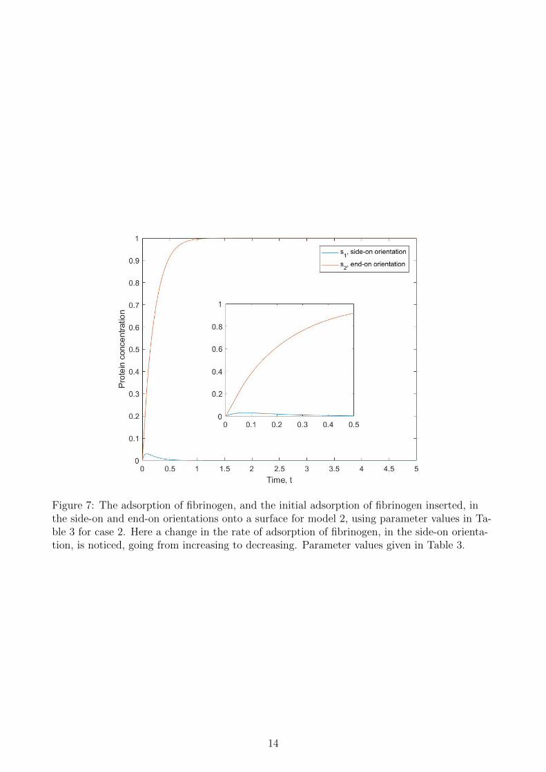
Figure 7: The adsorption of fibrinogen, and the initial adsorption of fibrinogen inserted, inthe side-on and end-on orientations onto a surface for model 2, using parameter values in Ta-ble 3 for case 2. Here a change in the rate of adsorption of fibrinogen, in the side-on orienta-tion, is noticed, going from increasing to decreasing. Parameter values given in Table 3.
14

Figure 8: An adsorption profile of fibrinogen using model 2, case 2. The adsorption is shownby a frequency shift, when adsorption occurs the frequency value reduces. With increasingprotein concentration, a greater frequency shift. Parameter values given in Table 3.
side-on orientation covers almost no binding sites. This switch in the s1 plot in Figure 7 isbecause our switch parameter values ψ1, ψ2, η1, η2 and s̃ for model 2, are now 0.06. However,this initial stage of adsorption in the s2 plot.
Since the aim of the model formulation is to replicate the experimental work published in [8],an adsorption profile was simulated to compare model 2, case 2, with the explicitly measureddata in Figure 2.
The adsorption of fibrinogen onto the surface is represented by a frequency shift, when ad-sorption occurs the frequency value will reduce. A sharp drop in the frequency value over ashort period of time represents a fast rate of adsorption. Since model 2 is dimensionless andthe parameter values are estimations, the results simulated from model 2 are not expected toreplicate Figure 2 exactly with respect to the frequency shift values, but the general shapeof the adsorption profile graph should be close to the shape of the adsorption profiles in Fig-ure 2. Since we are modelling the adsorption of fibrinogen onto a hydrophobic surface, we areonly comparing with the hydrophobic surface plot (circles) in Figure 2.
The shape of the adsorption profile in Figure 8 does not closely replicate the shape of theadsorption profile in Figure 2. There is no change of gradient in Figure 8 to reflect two differ-ent stages of adsorption. This suggests that parameter values for case 2 are not an accurateenough estimation to be used to model the adsorption behaviour of fibrinogen.
5.1.3 Case 3
The adsorption of fibrinogen, in either orientation, will occur first and the unbinding of end-on orientation closely following. The switch of orientations occurring after the first full ad-
15

Figure 9: The adsorption of fibrinogen, and the initial adsorption of fibrinogen (insert), inthe side-on and end-on orientations onto a surface for model 2, using parameter values in Ta-ble 3 for case 3. There is a change in the rate of adsorption of fibrinogen, going from increas-ing to decreasing, in the side-on orientation and also a change in rate, going from rapidly in-creasing to gradually increasing, in adsorption of the end-on orientated fibrinogen.
sorption of fibrinogen, where the rate of the switch from the side-on to the end-on orientatedthen happens very rapidly. This suggests that when fibrinogen adsorbs onto a hydrophobicsurface the reactions (1) and (2) occur first, and then reaction (3). Equivalently, in an ex-periment the rate of each reaction during adsorption is different; therefore, it is unrealistic toassume that the initial adsorption of end-on and side-on fibrinogen (k̂+1 , k̂+2 ), the desorptionof end-on and side-on fibrinogen (k̂−1 , k̂−2 ) and the orientation change (k̂+3 , k̂−3 ) occur at thesame time and rate during the adsorption process.
Since case 2 did not produce a close enough replication of the adsorption profile, we modifythe parameter estimations γ+3 , γ−3 , k+3 , k−3 , ψ1, ψ2, η1, η2 and s̃ as in Table 3, case 3.
Comparing Figure 9 with Figure 7, they are similar due to the fact that the end-on orienta-tion gains almost full coverage of the surface, as it tends to a concentration close to one, andthere are close to no side-on orientated fibrinogen bound on the surface at steady-state. How-ever the initial stage and second stage of adsorption can be recognised in both s1 and s2 plotsin Figure 9, whereas Figure 7 only showed a two stage adsorption for s1. As fibrinogen hasa two staged adsorption process [8], the parameter values for case 3 are found to provide amore accurate representation of the behaviour of fibrinogen.
Figure 10 shows an adsorption curve for fibrinogen using model 2, case3, which closely re-flects the adsorption curve in Figure 2, for the adsorption of fibrinogen onto a hydrophobicsurface produced from experimental results. A change in the rate of adsorption can be seenby a change in the gradient of the graph in Figure 10, where the fibrinogen molecules are
16

Figure 10: An adsorption profile of fibrinogen using model 2, case 3. The adsorption is shownby a frequency shift, when adsorption occurs the frequency value reduces. With increas-ing protein concentration there is a greater frequency shift; however, this is seen more so inthe initial stages of adsorption, then the second stage of adsorption. The rate of frequencychange reduces in the second stage of adsorption. Parameter values given in Table 3.
17

Figure 11: A derivative plot of the adsorption of fibrinogen using model 2, case 3. The firststage of adsorption can clearly be seen as the rapid drop in the frequency shift value to -2between time t=0 and t=0.0003. Parameter values given in Table 3.
changing orientation upon the surface, after the initial stage of adsorption has occurred.
The success of the adsorption profile for model 2, case 3, lead to the simulation of a deriva-tive plot, as a derivative plot has also been simulated using the experimental results from [8].
The adsorption process for fibrinogen using model 2, case 3, is more clearly visible in Fig-ure 11, compared to Figure 10, where the initial rapid adsorption is clearly visible, and thesecond stage of adsorption is not as visible, but can still be recognised. The adsorption pro-cess is meant to occur in a stepwise fashion as seen in Figure 2. As the adsorption profile formodel 2, case 3, reflects that in Figure 2, the derivative plot is also expected to reflect thatin Figure 2. However, this is not quite the case here, possible reasons for this which are dis-cussed in Section 6.
5.2 Steady-state analysis
Steady-state analysis was carried out on model 2, with the three different sets of parametervalues, finding both the number of steady-state values and characterising their stability. Dueto the complicated nature of model 2, the stability of the steady-states were determined bysimulation of the phase portraits.
5.2.1 Case 1
Case 1 exhibits bistability, producing three steady-state values, two of which are stable, asseen in Figure 12. For high initial values of s2, the solution trajectories tend towards the sta-
18

Figure 12: A phase portrait of model 2 using parameter values for case 1 (given in Table3), showing bistability, where the stable node (s1,s2)≈(0,1) is the desired result and is onlyachieved for an initial condition where s2 ≥0.5.
ble node (s1,s2)≈(0,1). However, for low initial values of s2, the trajectories tend towards thelower stable node where the steady-state value for s2 is lower than the steady-state value fors1, shown by Figure 12, which is experimentally unrealistic. In experiments carried out onfibrinogen, the initial concentration of side-on and end-on orientated fibrinogen bound to thesurface always starts at (s1,s2)=(0,0); therefore, the steady-state value of (s1,s2)≈(0,1) willnever be reached using these parameter values.
5.2.2 Case 2
Case 2 has switch point values ψ1, ψ2, η1, η2 and s̃ of 0.06, so that the problems with case 1are avoided. When the initial condition (s1,s2)=(0,0), the trajectories in the phase portraittend towards one stable node (s1,s2)≈(0,1), as shown in Figure 13.
19

Figure 13: A phase portrait of model 2 using parameter values for case 2 (given in Table 3),where there is one stable node at (s1,s2)≈(0,1).
The behaviour of fibrinogen adsorption is found to favour the full coverage of a surface withend-on orientated proteins only [8].
5.2.3 Case 3
Further improvements were made to switch values and reaction rates, making sure they donot all occur at the same time, these values are shown in Table 3, case 3, producing a similarphase portrait to Figure 13.
20

Figure 14: A phase portrait of model 2 using parameter values for case 3 (given in Table 3)showing one stable node at (s1,s2)≈(0,1) and a saddle point.
There are 2 steady-state values in Figure 14, only one of which is stable, (s1,s2)≈(0,1), theother being a saddle point. No matter what initial conditions are imposed the substrate sur-face will always end up almost fully covered with end-on orientated fibrinogen, which is whatwe would expect to see from fibrinogen [8].
6 Discussion
Looking at the adsorption of fibrinogen through protein concentration plots and conductingsteady-state analyses on models 1 and 2, it is clear that the use of modified tanh functions torepresent variable reaction rates is a more accurate way of reproducing experimental results,like those seen in [8], compared with constant reaction rates. Similar to the conclusion in [3],it is inaccurate to represent an orientation change purely on the density of binding sites eachorientation occupies; therefore, the modified tanh functions overcome this by taking into ac-count the surface chemistry, along with the interactions between the fibrinogen molecules andthe area occupied by the protein in each orientation.
It was suggested that the best value for β would be close to zero, throughout model 2, β wasset to be zero, although any small value, β ≤ 0.5, would still produce similarly shaped ad-sorption profiles.
It would be assumed that if the adsorption profile of fibrinogen produced by model 2 re-flected that from [8], that the derivative plots would do also. However, this is not the case.This may be due to the modified tanh functions in model 2 creating inconsistency in thederivative plot and the shape of the adsorption profile produced by model 2 not being asclose to the shape of the adsorption profile in Figure 2 as we think.
21

To overcome any errors due to the modified tanh functions in model 2, the orientation changesof fibrinogen could be represented as Hill functions, as demonstrated in [6] and [3]. In [6], aHill function for the adsorbed protein concentration was found by equating the ODE for thereaction to zero, which was then used to deduce the kinetic rate constants for the model. AHill function in [3] was made for the mass transport limitation (MTL) of the system, where‘MTL varies from 0, when the system is not mass transport limited, to 1, when the system isabsolutely mass transport limited’.
In the blood, fibrinogen would be in competition for binding sites on the surface of a bio-material. Drawing in the model of two compelling proteins (of uniform shape) adsorbing ontoa surface [10], model 2 could be improved by taking into consideration other competing pro-tein molecules, like albumin, that would more closely replicate the in vivo scenario.
A bio-material’s surface would not be flat when replacing three-dimensional damaged organsin the body. Therefore, surface curvature needs to be considered, as surface curvature wouldaffect the orientation of fibrinogen upon adsorption, it’s rearrangement of orientation afterinitial adsorption and the overall adsorption profile of fibrinogen.
A further improvement would be to fully parameterise model 2 and investigate how well theresults hold, comparing them with results from [8].
Overall, the modified tanh functions used to represent the reaction rates for fibrinogen of dif-ferent orientations have been seen to work well when comparing the simulations with experi-mental results from [8]. However, the factors, such as surface curvature and protein competi-tion, need to be considered when modelling the complicated nature of protein adsorption ona larger scale.
References
[1] Sandana A. and Sii D. Binding kinetics of antigen by immobilized antiboyd: Influence ofreaction order and external diffusional limitations. BIOSENS BIOELECTRON, 7:559–568, 1992.
[2] Krishnan K. Chittur. Ftir/atr for protein adsorption to biomaterial surfaces. BIOMA-TERIALS, 19:357–369, 1998.
[3] Micheal K. E., Vernekar V. N., Keselowsky B. G., Meredith J. C., Latour R. A., andGarcia A. J. Adsorption-induced conformational changes in fibronectin due to interac-tions with well-defined surface chemistries. LANGMUIR, 19(19):8033–8037, 2003.
[4] Chen H., Yuan L., Song W., Wu Z., and Li D. Biocompatible polymer materials: Role ofprotein-surface interactions. PROG POLYM SCI, 33:1059–1087, 2008.
[5] Vann C. J., Good R. J., and Chaudhury M. K. The role of van der waals forces and hy-drogen bonds in hydrophobic interactions between biopolymers and low energy surfaces.J COLLOID INTERF SCI, 111(2):378–390, 1986.
[6] Skidmore G. L., Horstmann B. J., and Chase H. A. Modelling single-component pro-tein adsorption to the cation exchanger s sepharose ff. J CHROMATOGR, 498:113–128,1990.
[7] Roach P. Measurement of surface-protein interactions on novel surfaces. PhD thesis,2005.
22

[8] Roach P., Farrar D., and Perry C. C. Interpretation of protein adsorption: Surface-induced conformational changes. J AM CHEM SOC, 127(22):8168–8173, 2005.
[9] Roach P., Farrar D., and Perry C. C. Surface tailoring for controlled protein adsorp-tion: Effect of topography at the nanometer scale and chemistry. J AM CHEM SOC,128(12):3939–3945, 2006.
[10] Roach P., Roberts P., and Butcher J. Designer materials to control competitive proteinbinding. MMSG 2012 Keele University, 2012.
[11] Hlady V. and Buijs J. Protein adsorption on solid surfaces. CURR OPIN CHEM BIOL,7:72–77, 1996.
23