models 91-3 u35-3 - for all your equipment hire needs€¦ · the manufacture of products may cause...
TRANSCRIPT

MODELS
OPERATOR'S MANUAL
1BAAGABAP02901BAAGABAP0280
English (Australia)Code No. RC468-8131-4
KX91-
3S2·U35-
3S2
PRINTED IN JAPAN © KUBOTA Corporation 2007
READ AND SAVE THIS MANUAL
KX91-3 · U35-3

KUBOTA Corporation is ···Since its inception in 1890, KUBOTA Corporation has grown to rank as one of the major firms in Japan.
To achieve this status, the company has through the years diversified the range of its products and services to a remarkable extent, until today, 19 plants and 16,000 employees produce over 1,000 different items, large and small.
All these products and all the services which accompany them, however, are unified by one central commitment. KUBOTA makes products which, taken on a national scale, are basic necessities. Products which are indispensable, products intended to help individuals and nations fulfill the potential inherent in their environment. For KUBOTA is the Basic Necessities Giant.
This potential includes water supply, food from the soil and from the sea, industrial development, architecture and construction, and transportation.
Thousands of people depend on KUBOTA's know-how, technology, experience and customer service. You too can depend on KUBOTA.
KX91-3S2/U35-3S2AO . I . 5 - 5 . 1 . AK
Abbreviations Description
LIST OF ABBREVIATION
American Petroleum Institute
American Society for Testing and Materials, USA
Committee for European Construction Equipment
German Institute for Standards, Federal Republic of Germany
European Standard
Falling Object Protective Structures
''Front'' means the front view towards the boom and dozer
High speed
International Standardization Organization
Japanese Industrial Standard
Volume (Liter)
Liter per minute
Low speed
Military Standards
Revolutions Per Minute
Roll-Over Protective Structures
Society of Automotive Engineers, USA
Two Pattern Selection System
Auto Idle
API
ASTM
CECE
DIN
EN
FOPS
FRONT
Hi
ISO
JIS
L
L/min
Lo
MIL
rpm
ROPS
SAE
TPSS
AI
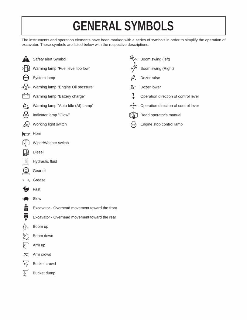
GENERAL SYMBOLSThe instruments and operation elements have been marked with a series of symbols in order to simplify the operation of excavator. These symbols are listed below with the respective descriptions.
Safety alert Symbol
Warning lamp ''Fuel level too low''
System lamp
Warning lamp ''Engine Oil pressure''
Warning lamp ''Battery charge''
Warning lamp ''Auto Idle (AI) Lamp''
Indicator lamp ''Glow''
Working light switch
Horn
Wiper/Washer switch
Diesel
Hydraulic fluid
Gear oil
Grease
Fast
Slow
Excavator - Overhead movement toward the front
Excavator - Overhead movement toward the rear
Boom up
Boom down
Arm up
Arm crowd
Bucket crowd
Bucket dump
Boom swing (left)
Boom swing (Right)
Dozer raise
Dozer lower
Operation direction of control lever
Operation direction of control lever
Read operator's manual
Engine stop control lamp

FOREWORD
3SAFETY FIRST
IMPORTANT :
NOTE :
3 DANGER :
3 WARNING :
3 CAUTION :
Indicates an imminently hazardous situation which, if not avoided, will result in death or serious injury.
Indicates a potentially hazardous situation which, if not avoided, could result in death or serious injury.
Indicates a potentially hazardous situation which, if not avoided, may result in minor or moderate injury.
Indicates that equipment or property damage could result if instructions are not followed.
Gives helpful information.
You are now the proud owner of a KUBOTA Excavator. This excavator is a product of KUBOTA quality engineering and manufacturing. It is made of fine materials and under a rigid quality control system. It will give you long, satisfactory service. To obtain the best use of your excavator, please read this manual carefully. It will help you become familiar with the operation of the excavator and contains many helpful hints about excavator maintenance. It is KUBOTA's policy to utilize as quickly as possible every advance in our research. The immediate use of new techniques in the manufacture of products may cause some small parts of this manual to be outdated. KUBOTA distributors and dealers will have the most up-to-date information. Please do not hesitate to consult with them.Please note that there may be some differences between your actual machine and the illustration in the instructions.
This symbol, the industry's ''Safety Alert Symbol'', is used throughout this manual and on labels on the machine itself to warn of the possibility of personal injury. Read these instructions carefully. It is essential that you read the instructions and safety regulations before you attempt to assemble or use this unit.
CONTENTS
SAFE OPERATION ................................................................................................. 1DEALER SERVICE...................................................................................................... 1
TECHNICAL DATA...................................................................................................... 2
DESCRIPTION OF MACHINE PARTS........................................................................ 3
INSTRUMENT PANEL AND CONTROL ELEMENTS................................................. 4
CHECKS BEFORE START ......................................................................................... 6DAILY CHECKS....................................................................................................... 6CAB TYPE MACHINES ........................................................................................... 6
Wiper/Washer Switch(CAB type only) ..............................................................................6Interior Lamp(CAB type only) ...........................................................................................6Heater Switch(CAB type)..................................................................................................7Opening/Closing of CAB Door(CAB type only).................................................................8Opening/Closing of Front CAB Window(CAB type only) ..................................................8Working Light Switch ........................................................................................................9Emergency Hammer(CAB type only)................................................................................9
OPERATION OF THE ENGINE................................................................................. 10STARTING THE ENGINE...................................................................................... 10
Display Selector Switch ..................................................................................................11Charge Lamp..................................................................................................................12Oil Lamp .........................................................................................................................12Glow Lamp......................................................................................................................12LCD Display for Normal Operation .................................................................................12LCD Display for Warning ................................................................................................13Warning Lamp ................................................................................................................14Checkpoints after Starting the Engine ............................................................................14
STARTING THE ENGINE UNDER COLD CONDITIONS...................................... 15STOPPING THE ENGINE...................................................................................... 15
Emergency Engine Stop Knob........................................................................................15STARTING WITH AN AUXILIARY BATTERY ....................................................... 16
Observe Following Guidelines when Starting with an Auxiliary Battery..........................16
EXCAVATOR OPERATION ...................................................................................... 17RUNNING-IN OF THE NEW EXCAVATOR........................................................... 17
Do not Work with Full Engine Rpm's or Full Loads during the First 50 Working Hours..17Oil Change in the Run-in Stage......................................................................................17Seat Belt .........................................................................................................................17
STARTING............................................................................................................. 17Operator's Seat...............................................................................................................17Lock Lever ......................................................................................................................18Working Light Switch ......................................................................................................19Travel Buzzer..................................................................................................................19
DRIVING ................................................................................................................ 19Drive Levers(Right,Left)..................................................................................................20Travel Speed Switch.......................................................................................................21

CONTENTS
TURNS................................................................................................................... 22Pivot Turn .......................................................................................................................22Spin Turn ........................................................................................................................23
UP AND DOWNHILL DRIVING.............................................................................. 23OPERATION OF THE DOZER .............................................................................. 24TWO PATTERN SELECTION SYSTEM(TPSS) .................................................... 24
Pattern Change...............................................................................................................24OPERATION OF THE BOOM................................................................................ 25OPERATION OF THE ARM................................................................................... 26OPERATION OF THE BUCKET ............................................................................ 26UNIT SWING AND BOOM SWING OPERATION.................................................. 27
Unit Swing Operation......................................................................................................27Boom Swing Operation...................................................................................................27
SERVICE PORT OPERATION .............................................................................. 28Service Port Operation ...................................................................................................28One Way Flow Operation ...............................................................................................32
1-way or 2-way CIRCUIT SELECTION VALVE OPERATION............................... 33AUTO IDLE (AI) OPERATION ............................................................................... 34IMPORTANT INFORMATION ON EXCAVATOR OPERATION............................ 34HOW TO RELEASE PRESSURE TRAPPED IN THE HYDRAULIC SYSTEM...... 35
TRANSPORTING THE EXCAVATOR ON A VEHICLE............................................. 36
LIFTING OF THE EXCAVATOR................................................................................ 38
MAINTENANCE......................................................................................................... 40MAINTENANCE INTERVALS................................................................................ 40OPENING AND CLOSING OF PARTS.................................................................. 43
Opening and Closing of the Fuel Tank Cap....................................................................43Opening/Closing of the Engine Hood .............................................................................43Opening/Closing of the Side Hood .................................................................................43Where to store the Tool and the Grease Gun.................................................................44Where to keep Operators Manual...................................................................................44
DAILY CHECKS..................................................................................................... 45Checking Coolant Level..................................................................................................45Checking Fuel Level .......................................................................................................45Checking Engine Oil Level..............................................................................................46Checking Hydraulic Oil Level..........................................................................................46Lubrication Points ...........................................................................................................47Checking Radiator and Oil Cooler ..................................................................................48Checking Washer Liquid(only for CAB type) ..................................................................48Checking and Cleaning Engine and Electrical Wiring.....................................................48Washing Whole Machine................................................................................................48
REGULAR CHECKS AND MAINTENANCE WORK ................................................. 49EVERY 50 SERVICE HOURS ............................................................................... 49
Draining Fuel Tank .........................................................................................................49Draining Water Separator ...............................................................................................49Battery ............................................................................................................................49Battery Charging.............................................................................................................50Greasing Swing Bearing Teeth.......................................................................................51
EVERY 200 SERVICE HOURS ............................................................................. 51Checking Fan Belt Tension.............................................................................................51

CONTENTS
Checking Radiator Hoses and Clamps...........................................................................51Inspection and Cleaning Air Filter Element.....................................................................52Air Filter Maintenance.....................................................................................................53Greasing Swing Bearing.................................................................................................53Checking Fuel Line and Intake Air Line ..........................................................................54
EVERY 250 SERVICE HOURS ............................................................................. 54Changing Engine Oil(First Engine Oil Change after 50 Service Hours) .........................54
EVERY 500 SERVICE HOURS ............................................................................. 55Replacing Engine Oil Filter(Replace the engine oil filter every 500 hours,or every 1 year in the case that service hour is less than 500 hours).............................55Drive unit Oil Change(First Oil Change at 100 hours) ....................................................55Replacing Fuel Filter Cartridge .......................................................................................56Replacing Hydraulic Return Filter Element(first replacement after 250 service hours) ..56
EVERY 1000 SERVICE HOURS ........................................................................... 57Hydraulic Oil Check for Machines with Hydraulic Breakers............................................57Hydraulic Oil Change(Including Replacing Suction Filterand Breather Filter Element in Hydraulic Tank)..............................................................57Replacing Hydraulic Pilot Filter Element.........................................................................58
EVERY 1000 SERVICE HOURS OR ONCE A YEAR ........................................... 58Replacing Air Filter Element ...........................................................................................58
EVERY 1500 SERVICE HOURS ........................................................................... 58Checking Fuel Injection Nozzle(Injection Pressure) .......................................................58
EVERY 2000 SERVICE HOURS ........................................................................... 58Changing Front Idler and Track Roller Oil ......................................................................58Checking Alternator and Starter Motor ...........................................................................58
EVERY 3000 SERVICE HOURS ........................................................................... 59Checking Injection Pump................................................................................................59
ANNUAL SERVICE................................................................................................ 59Electrical Wiring and Fuses ............................................................................................59
BIENNIAL SERVICING.......................................................................................... 59Replacing of Radiator Hoses..........................................................................................59Changing Radiator Coolant ............................................................................................59Replacing Fuel Hose ......................................................................................................60Replacing Intake Air line .................................................................................................60
OTHER ADJUSTMENTS AND REPLACEMENTS.................................................... 61PURGING FUEL SYSTEM .................................................................................... 61ADJUSTMENT OF TRACKS ................................................................................. 61
Rubber Tracks ................................................................................................................61Special Information when Using Rubber Tracks.............................................................62Steel Tracks....................................................................................................................62
CHANGING THE BUCKET.................................................................................... 63FUSES ................................................................................................................... 63
Replacing Fuses.............................................................................................................63Fuse Capacities and Circuits ..........................................................................................63Auxiliary Electric .............................................................................................................64Slow Blow Fuse ..............................................................................................................64
TROUBLESHOOTING............................................................................................... 65KUBOTA I.C.S. NAVIGATION LIST OF MESSAGES ........................................... 67
OPERATION UNDER COLD WEATHER CONDITIONS .......................................... 69

CONTENTS
PREPARATION FOR OPERATION IN COLD WEATHER.................................... 69PROCEDURE AFTER DONE WORK.................................................................... 69
LONG STORAGE...................................................................................................... 70
RECOMMENDED OILS............................................................................................. 72
APPENDICES............................................................................................................ 73MAIN DIMENSIONS .............................................................................................. 73
LIFTING CAPACITY.................................................................................................. 74

1SAFE OPERATION
SAFE OPERATION
The best insurance against accidents is to abide by thesafety regulations.Read and understand this manual carefully beforeoperating the excavator.Every user, however experienced, should carefully readand understand this manual and those of the attachmentsand accessories before taking the excavator intooperation. The owner is obliged to inform the operators ofthese instructions in detail.Keep this manual in the pocket under the seat.1. Make yourself acquainted with the excavator and beaware of its limits. Read the operating instructionscarefully before starting the excavator.
2. Obey the danger, warning and caution labels on themachine.
3. For your safety, ROPS/FOPS (Roll-Over ProtectiveStructures, Falling Objects Protective Structures.) witha seat belt is installed by KUBOTA. Always use theseat belt when the machine is equipped with a ROPS/FOPS. Do not modify structural members of ROPS bywelding, drilling, bending, grinding or cutting, as thismay weaken the structure. If any component isdamaged, replace it. Do not attempt repairs. If ROPSis loosened or removed for any reason, make sure allparts are reinstalled correctly. Tighten mounting boltsto proper torque.
4. The seat belt must be inspected regularly andreplaced if damaged.
5. Study control lever pattern A and pattern B. Thenchoose the one which is most familiar. Familiarizeyourself with the pattern selected by operation slowlyat low engine speed.
6. Do not operate the excavator while under the influenceof alcohol, medication, controlled substances or whilefatigued.
7. Check the surroundings carefully before using theexcavator or when attachments are being attached.
A Pay attention to the overhead clearance with electricwires.
A Check for pipes and buried cables before digging.A Check for hidden holes, hindrances, soft underground,
and overhangs.
1. BEFORE OPERATION
(1) Seat belt
(1) Pattern selector lever (Two Pattern Selection System: TPSS)
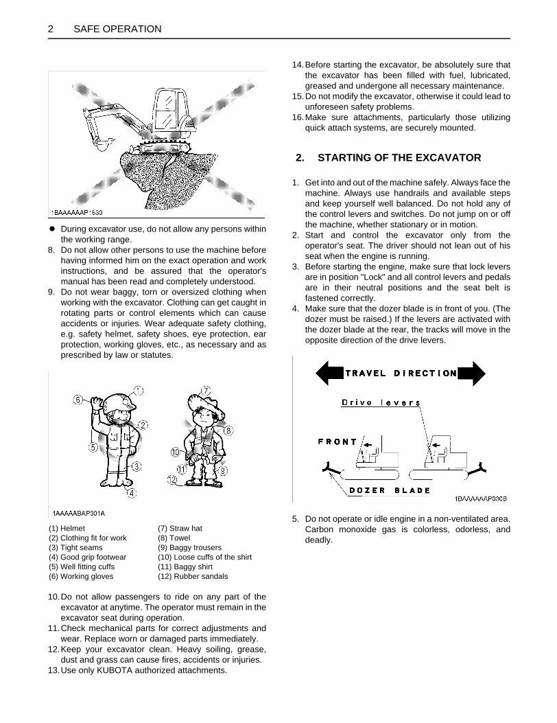
SAFE OPERATION2
A During excavator use, do not allow any persons withinthe working range.
8. Do not allow other persons to use the machine beforehaving informed him on the exact operation and workinstructions, and be assured that the operator'smanual has been read and completely understood.
9. Do not wear baggy, torn or oversized clothing whenworking with the excavator. Clothing can get caught inrotating parts or control elements which can causeaccidents or injuries. Wear adequate safety clothing,e.g. safety helmet, safety shoes, eye protection, earprotection, working gloves, etc., as necessary and asprescribed by law or statutes.
10.Do not allow passengers to ride on any part of theexcavator at anytime. The operator must remain in theexcavator seat during operation.
11.Check mechanical parts for correct adjustments andwear. Replace worn or damaged parts immediately.
12.Keep your excavator clean. Heavy soiling, grease,dust and grass can cause fires, accidents or injuries.
13.Use only KUBOTA authorized attachments.
14.Before starting the excavator, be absolutely sure thatthe excavator has been filled with fuel, lubricated,greased and undergone all necessary maintenance.
15.Do not modify the excavator, otherwise it could lead tounforeseen safety problems.
16.Make sure attachments, particularly those utilizingquick attach systems, are securely mounted.
1. Get into and out of the machine safely. Always face themachine. Always use handrails and available stepsand keep yourself well balanced. Do not hold any ofthe control levers and switches. Do not jump on or offthe machine, whether stationary or in motion.
2. Start and control the excavator only from theoperator's seat. The driver should not lean out of hisseat when the engine is running.
3. Before starting the engine, make sure that lock leversare in position "Lock" and all control levers and pedalsare in their neutral positions and the seat belt isfastened correctly.
4. Make sure that the dozer blade is in front of you. (Thedozer must be raised.) If the levers are activated withthe dozer blade at the rear, the tracks will move in theopposite direction of the drive levers.
5. Do not operate or idle engine in a non-ventilated area.Carbon monoxide gas is colorless, odorless, anddeadly.
(1) Helmet(2) Clothing fit for work(3) Tight seams(4) Good grip footwear(5) Well fitting cuffs(6) Working gloves
(7) Straw hat(8) Towel(9) Baggy trousers(10) Loose cuffs of the shirt(11) Baggy shirt(12) Rubber sandals
2. STARTING OF THE EXCAVATOR

3SAFE OPERATION
6. Keep all safety equipment and covers in place.Replace damaged or missing safety devices.
7. Precautions against tipping over. Keep away fromsteep slopes and embankments. Do not swing thebucket downhill. Lower the dozer during digging. Keepthe bucket as low as possible while driving uphill. Turnslowly on slopes (at reduced speed). Do not place theexcavator near the edges of trenches and banks, asthe earth can give away due to the weight of theexcavator.
8. Watch out at all times for the area to which theexcavator is being moved. Pay attention to any hindrances.
C Safety for childrenTragedy can occur if the operator is not alert to thepresence of children. Children generally are attracted tomachines and the work they do.1. Never assume that children will remain where you last
saw them.2. Keep children out of the work area and under the
watchful eye of another responsible adult.3. Be alert and shut your machine down if children enter
the work area.4. Never carry children on your machine. There is no safe
place for them to ride. They may fall off and be runover or interfere with your control of the machine.
5. Never allow children to operate the machine evenunder adult supervision.
6. Never allow children to play on the machine or on theattachments.
7. Use extra caution when backing up. Look behind anddown to make sure the area clear before moving.
8. When parking your machine, if at all possible, park ona firm, flat and level surface; if not, park across a slope. Lower the bucket and dozer to the ground, remove thekey, place the control lock levers in the locked positionfrom the ignition and lock the cab door (if equipped),before you leave.
Before leaving the machine,A Park the excavator on a firm, flat and level surface.A Lower the attachments and the dozer blade to the
ground.A Stop the engine.A Release pressure trapped in the hydraulic system.A Lock all control levers.A Remove the key.
3. AFTER OPERATION
(1) Lock lever for control lever (A) "Unlock"(B) "Lock"
SAFE OPERATION4
1. Observe all regulations concerning the transport ofexcavators on public roads.
2. Use adequately long and robust ramps when loadingon a vehicle. (for details see "TRANSPORTING THEEXCAVATOR ON A VEHICLE")
3. Do not change the running direction and to avoid atipping over, do not try to swing the attachmentcrosswise to the loading ramps.
4. Lower the attachment on the loading plane andrelease the pressure from the hydraulic system. Block the tracks with blocks and tie down theexcavator. After loading the excavator on the vehicle,securely tie down the undercarriage of the excavatorusing suitable chains, tensioners and approvedmethods.
5. Avoid abrupt braking of the vehicle with the excavatorloaded. The excavator may shift causing on accident.
6. If the excavator is to tow another machine, make surethe load is smaller than the strength of the hook, towchain or cable.
7. Do not use hooks on the roof of canopy or cabin forlifting the excavator.
Before doing maintenance work on the excavator, placethe machine on even solid ground, lower the attachmentsto the ground, stop the engine , release pressure trappedin the hydraulic system and remove the key. Whendismantling hydraulic parts, make sure that the hydraulicoil has cooled down sufficiently to avoid burns. Start maintenance work carefully, e.g. loosen plug slowlyso that oil will not squirt out.1. Before doing work on the engine, the exhaust system,
the radiator and the hydraulics, let the excavator cooldown sufficiently.
2. Turn off the engine at all times when filling with fuel.Avoid spilling and over-filling of fuel.
3. Smoking is prohibited while refueling or handling thebattery! Keep sparks and fire away from the fuel tankand battery. Flammable gases escape from thebattery, especially during charging.
4. Do not use or charge the refillable type battery if thefluid level is below the LOWER (lower limit level) mark.Otherwise, the battery component parts may beprematurely deteriorated, which may shorten thebattery's service life or cause an explosion. Check thefluid level regularly and add distilled water as requiredso that the fluid level is between the UPPER andLOWER levels.
5. Read and follow the directions "STARTING WITH ANAUXILIARY BATTERY" in "OPERATION OF THEENGINE", when starting with an auxiliary battery.
6. Keep a first-aid box and a fire extinguisher at hand atall times.
7. Do not open the radiator cap before the radiator hascooled down sufficiently First loosen the cap to the first stop and allow thesystem enough time to release the remainingpressure. Then loosen the cap completely.
8. To avoid short-circuiting the battery, always removethe ground cable first and attach the plus cable first.
9. Leaking hydraulic fluid has enough pressure topenetrate the skin and cause serious injuries.Leakages from pin holes can be totally invisible. Donot use hands for checking for leaks. Always use apiece of wood or cardboard. It is stronglyrecommended to use a face mask or eye protection. Should injuries occur with leaking hydraulic fluid,contact a doctor immediately. This fluid can causegangrene or serious allergic reactions.
4. SAFE LOADING AND TRANSPORT OF THE EXCAVATOR
Max. drawbar pull at coupling hook 70450 N (7183 kgf)
Max. vertical load at coupling hook 7210 N (735 kgf)
5. MAINTENANCE

5SAFE OPERATION
10.To avoid environmental damage from acid and heavymetals, do not throw the battery away.
11.Observe all laws and regulations concerning thedisposal of used oil, coolants, solvents, hydraulicfluids, battery acids and batteries.
12.To avoid fire, do not heat the hydraulic components(tanks, pipes, hoses, cylinders) before they have beendrained and washed.
13.Use a face mask or eye protection to protect the eyesand respiratory system against dust and other foreignparticles.
14.Securely support excavator with stands or suitableblocking before working underneath. For your safety,do not work under any hydraulically supporteddevices. They can settle, suddenly leak down, or beaccidentally lowered.
15.Do not dismantle the spring of the track tensioner. Ifdismantling is necessary, contact your KUBOTAdealer where the machine was purchased, orcompetent service shop. The assembly must be doneaccording to the work shop manual of KUBOTA(W.S.M.) for the product involved.
16.KUBOTA uses no parts which are lined with asbestos.Do not use these kind of parts even if they areavailable and can be installed.

SAFE OPERATION6
6. DANGER, WARNING AND CAUTION LABELS

7SAFE OPERATION

SAFE OPERATION8
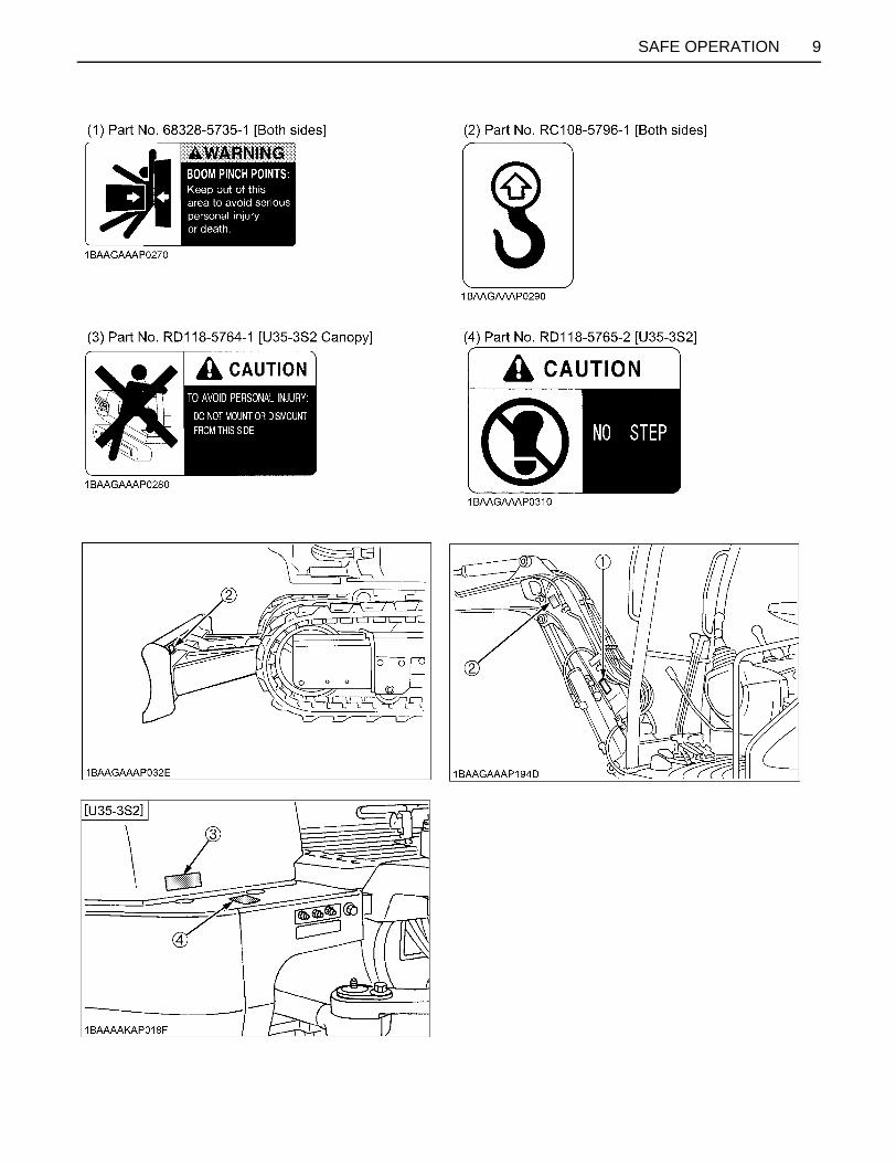
9SAFE OPERATION

SAFE OPERATION10
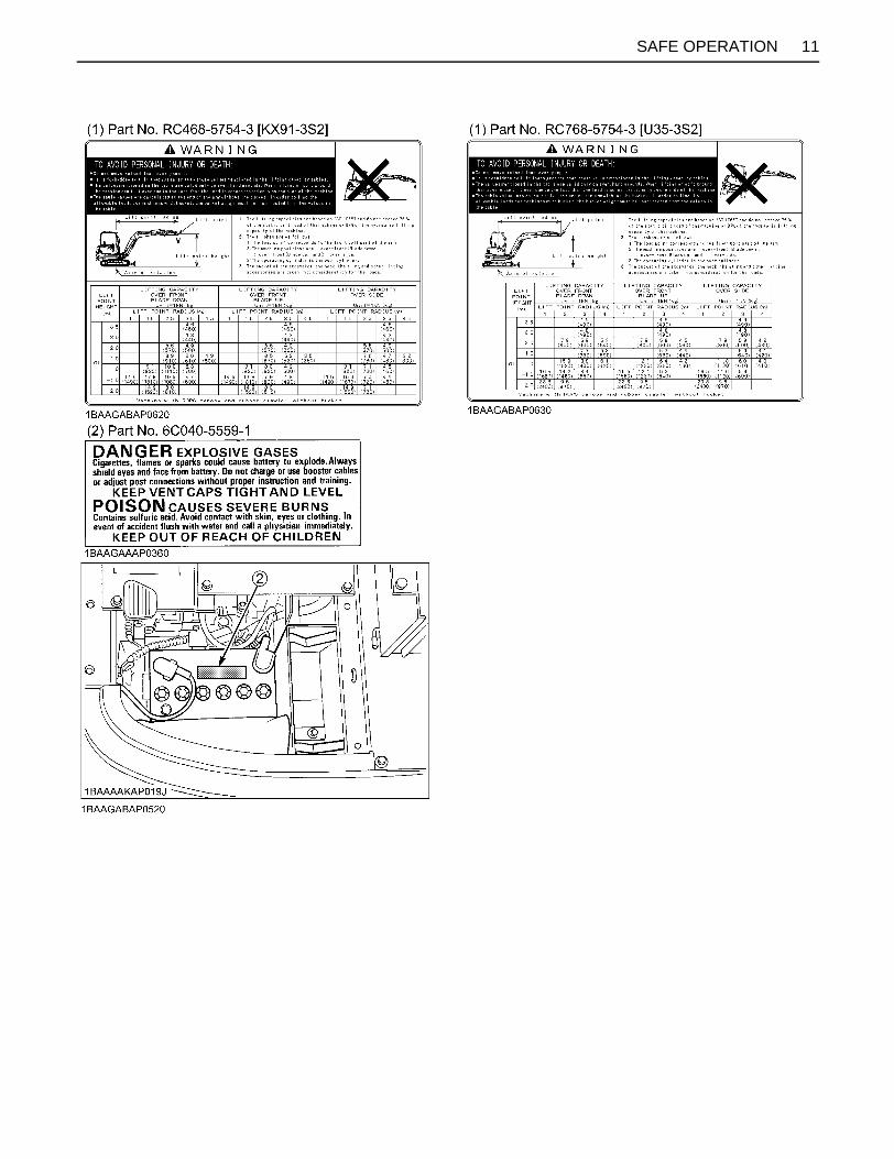
11SAFE OPERATION

SAFE OPERATION12

1DEALER SERVICE
DEALER SERVICE
Your KUBOTA dealer is always ready to help so that yourexcavator offers the best performance. After havingcarefully read these instruction, you will realize that muchof the routine maintenance can be done by yourself. YourKUBOTA dealer is responsible for servicing and thedelivery of spare parts. When ordering spare parts fromyour KUBOTA dealer, always mention the serial numberof the excavator and the engine. Note these numbers right away in the supplied lines.Model Serial No.
Excavator
Engine
Dealer's name (To be filled in through the owner)
(1) Serial No.
(1) Engine serial No.
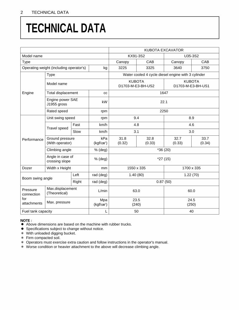
2 TECHNICAL DATA
TECHNICAL DATA
A Above dimensions are based on the machine with rubber trucks.A Specifications subject to change without notice.D With unloaded digging bucket.D Firm compacted soil.D Operators must exercise extra caution and follow instructions in the operator's manual.D Worse condition or heavier attachment to the above will decrease climbing angle.
KUBOTA EXCAVATORModel name KX91-3S2 U35-3S2Type Canopy CAB Canopy CABOperating weight (including operator's) kg 3225 3325 3640 3750
Engine
Type Water cooled 4 cycle diesel engine with 3 cylinder
Model name KUBOTA D1703-M-E3-BH-US2
KUBOTA D1703-M-E3-BH-US1
Total displacement cc 1647
Engine power SAE J1955 gross kW 22.1
Rated speed rpm 2250
Performance
Unit swing speed rpm 9.4 8.9
Travel speedFast km/h 4.8 4.6
Slow km/h 3.1 3.0
Ground pressure (With operator)
kPa (kgf/ )
31.8 (0.32)
32.8 (0.33)
32.7 (0.33)
33.7 (0.34)
Climbing angle % (deg) *36 (20)
Angle in case of crossing slope % (deg) *27 (15)
Dozer Width x Height mm 1550 x 335 1700 x 335
Boom swing angleLeft rad (deg) 1.40 (80) 1.22 (70)
Right rad (deg) 0.87 (50)
Pressure connection for attachments
Max.displacement (Theoretical) L/min 63.0 60.0
Max. pressure Mpa (kgf/ )
23.5 (240)
24.5 (250)
Fuel tank capacity L 50 40
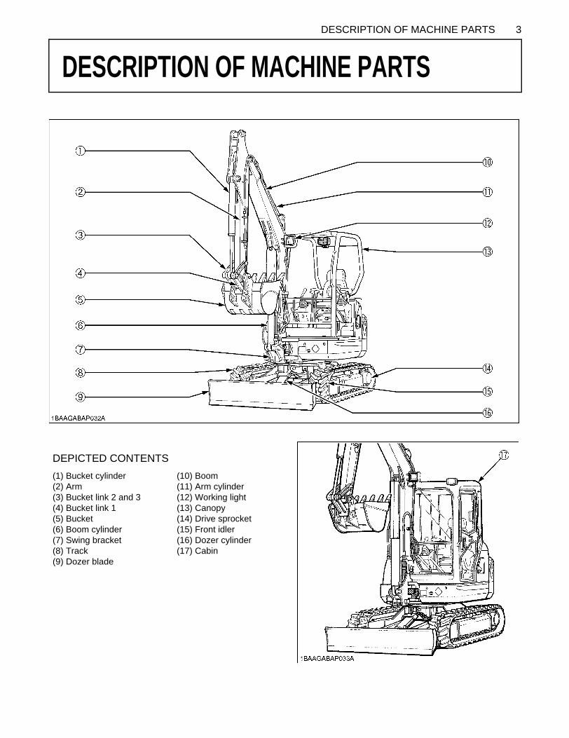
3DESCRIPTION OF MACHINE PARTS
DESCRIPTION OF MACHINE PARTS
DEPICTED CONTENTS(1) Bucket cylinder (2) Arm (3) Bucket link 2 and 3 (4) Bucket link 1 (5) Bucket (6) Boom cylinder (7) Swing bracket (8) Track (9) Dozer blade
(10) Boom (11) Arm cylinder (12) Working light (13) Canopy (14) Drive sprocket (15) Front idler (16) Dozer cylinder (17) Cabin

4 INSTRUMENT PANEL AND CONTROL ELEMENTS
INSTRUMENT PANEL AND CONTROL ELEMENTS
B Instrument Panel, SwitchesDEPICTED CONTENTS(1) Cup holder (U35-3S2) (2) Service port switch (3) Horn switch (4) Breaker lock switch (5) Travel speed switch (6) Speed indicator light (7) Starter switch (8) LCD display (9) Flow volume setting switch
(10) Switch for Auto idle control (11) Heater switch (CAB type only) (12) Emergency engine stop knob (13) Cup holder (KX91-3S2) (14) Wiper / Washer switch (CAB type only) (15) Working Light switch (16) Service port activation switch (17) Display selector switch (18) Warning lamp
5INSTRUMENT PANEL AND CONTROL ELEMENTS
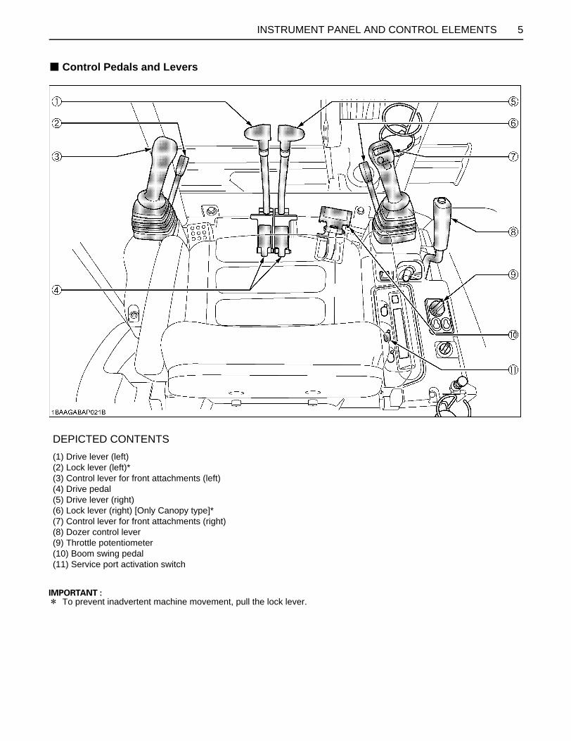
B Control Pedals and Levers
D To prevent inadvertent machine movement, pull the lock lever.
DEPICTED CONTENTS(1) Drive lever (left) (2) Lock lever (left)* (3) Control lever for front attachments (left) (4) Drive pedal (5) Drive lever (right) (6) Lock lever (right) [Only Canopy type]* (7) Control lever for front attachments (right) (8) Dozer control lever (9) Throttle potentiometer (10) Boom swing pedal (11) Service port activation switch

6 CHECKS BEFORE START
CHECKS BEFORE START
DAILY CHECKSIn order to avoid damage, it is important to check thecondition of the excavator before starting.To avoid personal injury:A Do maintenance work on the excavator only on
level ground with the engine off and the locklever in the "Lock" position.
Checks Go around the excavator and check for visual damageand wear. Check coolant level. (See regular checkpoints in thechapter on maintenance.)Check fuel level.Check engine oil level.Check hydraulic fluid level.Check air filter for clogging.Check all control lamps, indicators, tachometer and hourmeter.Check the light system. Check the seat belt and the ROPS/FOPS safety device. Check the condition of the safety and warning labels.(See "DANGER, WARNING AND CAUTION LABELS" in"SAFE OPERATION".)
CAB TYPE MACHINESBWiper/Washer Switch(CAB type only)Turn the starter switch to position "RUN" and push theswitch for the wiper and washer system; the wiper willbegin to move. A further push on the switch will activatethe washer system.A Do not activate the switch if the tank for the cleaning
fluid is empty; the pump can be damaged.A This can also be the case if the wiper is moved on a
dry window. In this case, make sure that cleaning fluidis applied to the pane before activating the wiper.
A In frosty conditions, make sure that the wiper blade isnot frozen to the glass before switching-on. The motorcan be damaged if the wiper system is used undersuch conditions.
BInterior Lamp(CAB type only)To turn on the interior lamp, set the starter switch to the"RUN" and then the interior lamp switch to the "ON"positions, respectively.
(1) Wiper switch
(1) Interior lamp

7CHECKS BEFORE START
BHeater Switch(CAB type)Turn the starter switch to position "RUN" and turn theheater switch clockwise, the heater fan will be activatedand the CAB will start to warm up. The heater has twopositions - "Low" and "High" -.
A During the summer, turn the heater valve clockwise toclose the valve.
C Recirculation / Fresh Air Selection knobA FRESH AIR: Set the knob to the position, and
fresh air will flow into the CAB. This is helpful when youwork in a dusty conditions or if the glass windows getfoggy.
A RECIRCULATION: Set the knob to the position,and the in-CAB air will be recirculated.This is useful forheating the CAB quickly or keeping it extra warm.
A When heating, do not keep the knob at the"RECIRCULATION" position for a long time. Thewindshield easily gets foggy.
A While working in a dusty conditions, keep the knob atthe "FRESH AIR" position. This increases thepressure in the CAB, which helps prevent dust fromcoming into the CAB.
(1) Heater switch (A) Pos. "High"(B) Pos. "Low"(C) Pos. "Off"
(1) Heater outlet
(1) Heater valve (A) Open(B) Close
(1) Recirculation/ fresh air selection knob
"FRESH AIR""RECIRCULATION"

CHECKS BEFORE START8
BOpening/Closing of CAB Door(CAB type only)
1. Unlock the CAB door and pull the knob. Open the CABdoor fully until fixed into place.
2. To close the CAB door, push the release lever downand close the door.
3. When leaving the excavator, always lock the door.
BOpening/Closing of Front CAB Window(CAB type only)
To avoid personal injury:A Keep hands and feet away from the area
between front window and CAB frame.Otherwise the operator risks serious injuriesby pinching or crushing.
A Other persons should stay away when openingthe window.
To open and close the front window, take the steps below.1. Release the lock levers on the top of the front window.
2. Hold the top and bottom grips tightly with both hands.Pull the top grip slightly upward and toward yourself tolet the windshield slide inward.
3. Pull the windshield all the way to the rubber at the backof the CAB. Tighten up the lock levers.
(1) Door knob
(1) Release lever (A) Down
(1) Lock levers (2) Grip
9CHECKS BEFORE START
4. To close the window, take the reverse steps 3, 2 and 1.
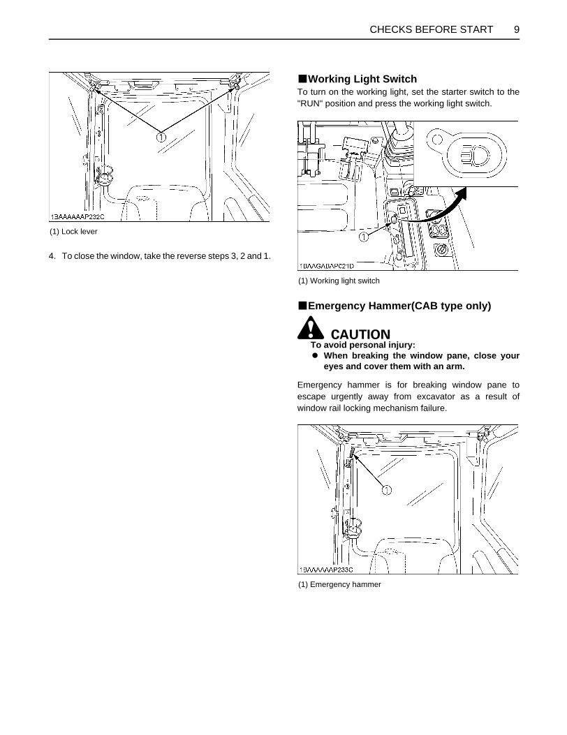
BWorking Light SwitchTo turn on the working light, set the starter switch to the"RUN" position and press the working light switch.
BEmergency Hammer(CAB type only)
To avoid personal injury:A When breaking the window pane, close your
eyes and cover them with an arm.
Emergency hammer is for breaking window pane toescape urgently away from excavator as a result ofwindow rail locking mechanism failure.
(1) Lock lever
(1) Working light switch
(1) Emergency hammer

10 OPERATION OF THE ENGINE
OPERATION OF THE ENGINE
To avoid personal injury: A Read "SAFE OPERATION" at the beginning of
this operator's manual.A Obey the danger, warning and caution labels
on the excavator. A To avoid the danger of exhaust fume
poisoning, do not operate the machine in aclosed building without proper ventilation.
A Always start the engine from the operator'sseat. Do not start the engine while standingnext to the excavator. Before starting theengine, sound the horn to get the attention ofpersons standing nearby.
A Do not use starting fluid or ether.A In order not to overload the battery and starter, avoid
start-ups of more than 10 sec.A When engine does not start in 10 sec., please wait 20
sec. or more, before attempting to restart.
STARTING THE ENGINE
To avoid personal injury:A The operator should not depend solely on the
warning lamps, but should always conduct theroutine checks (see "MAINTENANCE").
Start the engine in the following manner:1. Before starting the engine, make sure that all control
levers are in the neutral positions.
2. Pull the lock levers all the way back. (lock position)3. Turn the throttle potentiometer towards the
symbol.
(1) Horn switch
(1) Drive lever (left) (2) Drive lever (right)(3) Attachment control lever (left) (4) Attachment control lever (right) (5) Lock lever (left)(6) Lock lever (right) (Only Canopy type)
(1) Throttle potentiometer
11OPERATION OF THE ENGINE
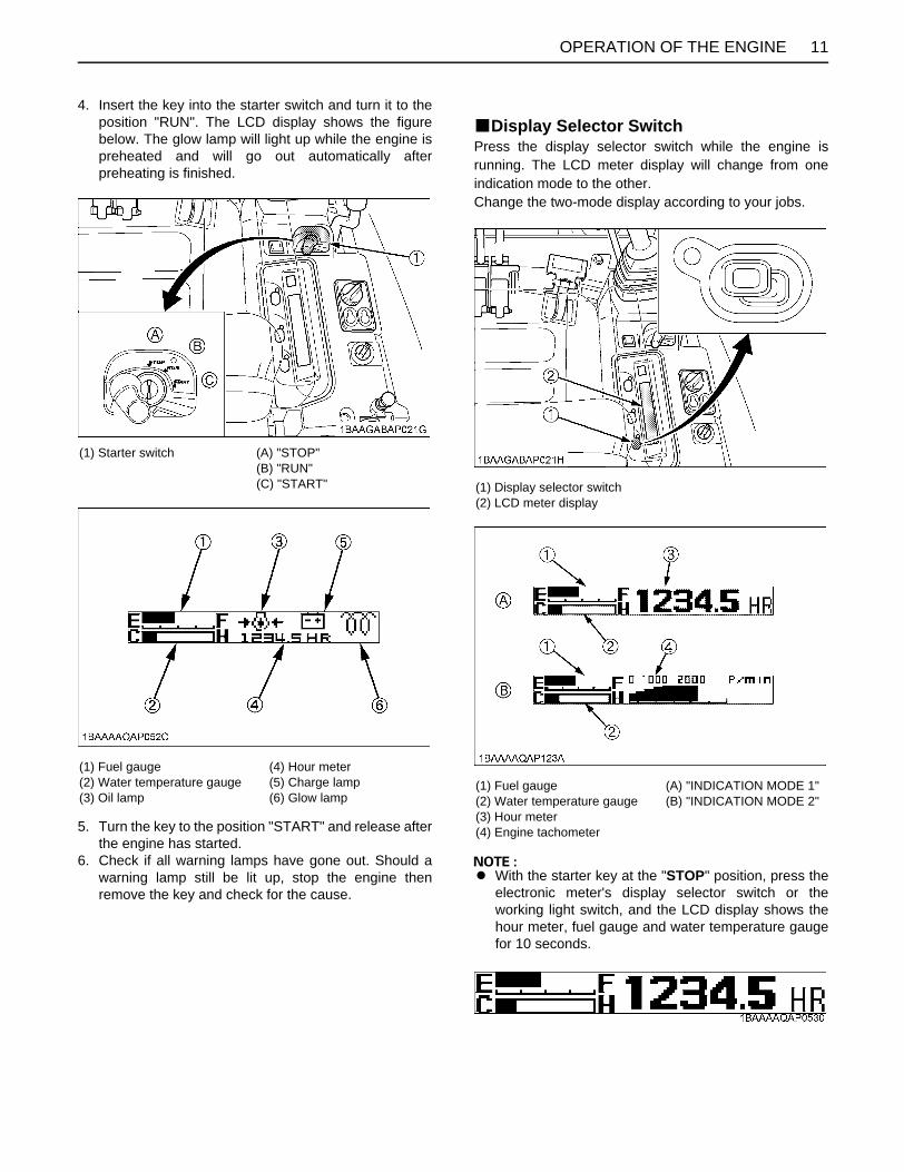
4. Insert the key into the starter switch and turn it to theposition "RUN". The LCD display shows the figurebelow. The glow lamp will light up while the engine ispreheated and will go out automatically afterpreheating is finished.
5. Turn the key to the position "START" and release afterthe engine has started.
6. Check if all warning lamps have gone out. Should awarning lamp still be lit up, stop the engine thenremove the key and check for the cause.
BDisplay Selector SwitchPress the display selector switch while the engine isrunning. The LCD meter display will change from oneindication mode to the other. Change the two-mode display according to your jobs.
A With the starter key at the "STOP" position, press theelectronic meter's display selector switch or theworking light switch, and the LCD display shows thehour meter, fuel gauge and water temperature gaugefor 10 seconds.
(1) Starter switch (A) "STOP"(B) "RUN"(C) "START"
(1) Fuel gauge(2) Water temperature gauge(3) Oil lamp
(4) Hour meter(5) Charge lamp(6) Glow lamp
(1) Display selector switch(2) LCD meter display
(1) Fuel gauge(2) Water temperature gauge(3) Hour meter(4) Engine tachometer
(A) "INDICATION MODE 1"(B) "INDICATION MODE 2"

OPERATION OF THE ENGINE12
BCharge LampThis warning lamp lights up if the charging system failswhile the engine is running. When the starter switch isturned "ON" with the engine off, the lamp lights up, andwhen the engine gets started, the lamp goes out.
A If there is disconnection or failure in the chargingsystem when the key is turned to "RUN", the following
symbol will appear.
BOil LampThe engine oil pressure warning lamp lights up due tofailure of the lubricating system with the engine running.When the starter switch is turned "ON" with the engineoff, this lamp lights up, and when the engine starts, thelamp goes out. If the lamp stays on with the enginerunning, stop the engine and check the engine oil level.
A If there is disconnection, failure or breakdown in thelubricating system when the key is turned to "RUN",the following symbol will appear.
BGlow LampWith the starter key at the "RUN" position, the engine'spreheat status is indicated.
A When the starter switch is turned to the "RUN"position, the engine will be preheated for a givenperiod of time and the lamp will turn on.
A The above indication appears momentarily when theengine is started, but it does not mean any trouble.(This is because the oil charge sensor output becomesunstable when the engine is started.)
A The symbol appears momentarily as the enginestarts. This is not an error.
BLCD Display for Normal OperationC Fuel gauge
To avoid personal injury:A Before adding fuel, be sure to stop the engine.A Be sure to keep open flame away from the
machine. Otherwise a fire may be caused.
With the starter key at the "RUN" position, the fuelremaining in the fuel tank is indicated in the block.
A If the fuel gauge indicator is near the "E" or the "FUEL"message appears, add fuel as soon as possible. If theindicator is near "E" and the machine runs on a slope,the engine may run out of fuel and get interrupted.
C Fuel supplyThe following functions are helpful when adding the fuel.The fueling progress can be monitored by a buzzer sound.
Procedure1. Press the work light switch or the display selector
switch on the meter with the key OFF. (Keep the keyat OFF.)
2. The message shown above appears.3. Add fuel.4. The buzzer sound interval changes according to the
amount fuel added. As the fuel amount becomes closeto full, the buzzer sound changes to continuousbeeping.
(1) Fuel gauge (A) "Empty"(B) "Full"

13OPERATION OF THE ENGINE
To avoid personal injury:A If the fuel is poured too fast, the buzzer may not
sound according to the fueling process.A The moment when the fuel tank is nearly full,
the buzzer starts beeping.A Look into the fuel tank when pouring the fuel.
Listen to the buzzer sound for a rough estimateof the fill-up progress.
C Water Temperature Gauge
To avoid personal injury:A Do not open the radiator cap during or just after
operation. Hot water may gush out and scaldyou. Wait for the water to cool down beforeopening the cap.
With the starter key at the "RUN" position, the coolingwater temperature is indicated. If the water temperatureindicator is near "H", take the steps below.1. Discontinue the job.2. Reduce engine rpm's to idle and keep it at idle for 5
minutes.3. Stop the engine and check the following points (1)-(3).
(1) Low coolant level or leak(2) Fan belt tension(3) Mud or dust deposits on radiator
C Hour-meterIndicates the total operating hours of the machine.
How the indicator worksA The meter advances one hour after an hour of
operation regardless of the engine rpm.
C Engine tachometerIndicates the current rpm of the engine.
A The LCD display may be illegible when viewed from acertain angle. This is not a display failure.
BLCD Display for WarningC Remaining fuel warningWhen the fuel level is very low, the lamp (yellow) startsflashing and the following message appears in thedisplay.
C Battery charge warningIf the charging system fails, the lamp (red) startsflashing and the following message appears in thedisplay.
(1) Water temperature gauge (A) "WATER TEMP LOW"(B) "WATER TEMP HIGH"

OPERATION OF THE ENGINE14
C Engine oil pressure low warningWhen the engine oil pressure drops too low, the lamp(red) starts flashing and the following message appears inthe meter.Immediately stop the engine and check the engine oillevel.
BWarning LampA The warning lamp is used to indicate broken wire,
short-circuit, fuel shortage and other problems.
A Warnings and errors are displayed and an alarmbuzzer beeps.
A The warning lamp starts flashing in red if any troubleoccurs. If the system gets in warning signal, thewarning lamp starts flashing in yellow.
A Do not just look at the meter, but also carry out theinspection and correction accordingly.
A Let your KUBOTA dealer inform you of detailsconcerning care and maintenance.
BCheckpoints after Starting the EngineAfter starting the engine, but before starting operation,check the following points:1. Turn the throttle potentiometer down and let the
engine idle for approx. five minutes. This allows theengine lubricant to warm up and penetrate every partof the engine.
A This idling is usually called "Warm-up".
2. Once the engine has warmed up, check:A the warning lamp "Engine oil pressure" has gone
out.A the warning lamp "Battery charge" goes out when
engine speed is increased.A the color of the exhaust is normal and no abnormal
noises or vibrations are heard or felt.A no fluid is leaking from pipes or hoses.
C Should any following conditions occur, stop theengine immediately.
A The engine rpm's increases or decreases suddenly. A Sudden abnormal noises are heard.A Exhaust is black.A Warning lamp for engine oil lights up during operation.
A In these cases, the excavator must be checked andserviced by your local the KUBOTA dealer.
(1) Warning lamp (red, yellow)(2) LCD display

15OPERATION OF THE ENGINE
STARTING THE ENGINE UNDER COLD CONDITIONS
To avoid personal injury:A Make sure that the lock lever is in the lock
position during warm up.
Start the engine in the following manner;1. Pull the lock levers all the way back (lock position).2. Turn the starter switch to the position "RUN" (glow
position) and keep until the indicator lamp has goneout.
3. Move the starter switch to the position "START"; tocrank and start engine.
4. Release the starter switch after the engine has started;it will automatically return to the position "RUN ".
A Let the engine warm up after start-up.A Let the engine warm up after start-up for approx. 10
minutes under no load conditions. If the hydraulic fluidtemperature is too low, the operations will be affected. Do not operate the excavator under full load before theengine has warmed up enough.
STOPPING THE ENGINE
To avoid personal injury or death:A Do not keep the bucket or dozer in the lifted
position, as a person could accidentally touchthe levers and cause serious accidents.
BEmergency Engine Stop Knob
To avoid personal injury:A Pull the engine stop knob up and hold it until
the engine stops in case of emergency.
The engine stops when the key is turned off. If the enginedoes not stop, pull the engine stop knob up and hold ituntil the engine stops. After the engine has stopped, besure to push the engine stop knob back in, or the enginewill not start next time.
A If the engine does not stop with the key, contact yourKUBOTA dealer.
1. After slowing the engine to idle, turn the key to "STOP".
2. Remove the key.
(1) Emergency engine stop knob

OPERATION OF THE ENGINE16
STARTING WITH AN AUXILIARY BATTERY
To avoid personal injury: A Battery gases can explode.
Do not smoke and keep sparks and flamesaway.
A Do not start the engine with an auxiliary batteryif excavator battery is frozen.
A Do not connect the black jumper cable to thenegative (-) terminal of the excavator battery.
BObserve Following Guidelines when Starting with an Auxiliary Battery
1. Bring the helping machine with the same batteryvoltage as near as possible to the machine. THE MACHINES MUST NOT COME IN CONTACTWITH EACH OTHER.
2. Bring the levers and pedal of both machines in theneutral position.
3. Wear eye protection and rubber gloves.4. Ensure the vent caps are securely in place (if
equipped).5. Connect the terminal of the red jumper cable with the
plus (+) terminal of the low battery and connect theother end of the cable to the plus (+) terminal of theauxiliary battery.
6. Connect the black negative cable to the minus (-)terminal of the auxiliary battery.
7. Connect the other end of the black cable (coming fromthe auxiliary battery) to the machine frame as far awayas possible from the low battery.
8. Start the engine of the helping machine and let it runfor a while. Start the machine with the low battery.
9. Disconnect the jumper cables in the reversesequence.
A This excavator has a negative (-) earthed 12 Voltstarting system.
A Only use the same voltage when using an auxiliarybattery.
A Using a higher voltage will cause serious damage tothe electrical system. When using an auxiliary battery,only the compatible (same) voltage is permissible.
(1) Low battery(2) Auxiliary battery(3) Jumper cables
17EXCAVATOR OPERATION
EXCAVATOR OPERATION
RUNNING-IN OF THE NEW EXCAVATORThe operation and care of the new excavator influencesits life span. Your new excavator has been carefullychecked and tested before leaving the factory. In spite ofthis, all movable components must run-in during the first50 work hours. Do not work with full rpm's and full loadsduring this period. It is most important to run-in yourexcavator properly in order to achieve its full performanceand longevity. During the running-in, the following pointsshould be adhered to in all cases.BDo not Work with Full Engine Rpm's or Full Loads during the First 50 Working Hours
A Let the engine warm up sufficiently in the cold season.A Do not let the engine rev-up more than necessary.
BOil Change in the Run-in StageThe lubrication oil plays a specific and important roleduring the run-in phase of the excavator. The numerousmovable parts are not yet run-in, so many fine metalparticles are generated and cause damage and shortenthe life of many components. Pay attention to the oil-change intervals and complete them sooner than later.See "REGULAR CHECKS AND MAINTENANCE WORK"section for more details on the oil-change intervals.
BSeat Belt
To avoid personal injury or death:A Always use the seat belt with a ROPS/FOPS
protection structure. Adjust the seat to theoptimal position and buckle up.
STARTING
BOperator's Seat
To avoid personal injury:A Make sure that the seat is completely secured
after each adjustment.A Do not allow any person other than the driver to
ride on the excavator.
(1) Seat belt
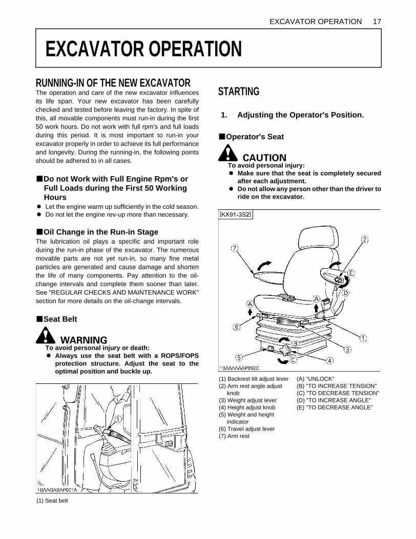
1. Adjusting the Operator's Position.
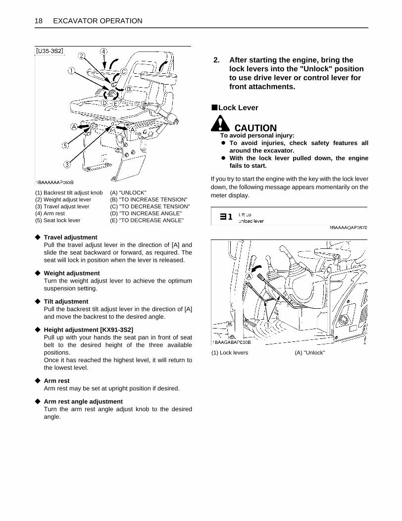
(1) Backrest tilt adjust lever(2) Arm rest angle adjust knob(3) Weight adjust lever(4) Height adjust knob(5) Weight and height indicator(6) Travel adjust lever(7) Arm rest
(A) "UNLOCK"(B) "TO INCREASE TENSION"(C) "TO DECREASE TENSION"(D) "TO INCREASE ANGLE"(E) "TO DECREASE ANGLE"
EXCAVATOR OPERATION18
C Travel adjustmentPull the travel adjust lever in the direction of [A] andslide the seat backward or forward, as required. Theseat will lock in position when the lever is released.
C Weight adjustmentTurn the weight adjust lever to achieve the optimumsuspension setting.
C Tilt adjustmentPull the backrest tilt adjust lever in the direction of [A]and move the backrest to the desired angle.
C Height adjustment [KX91-3S2]Pull up with your hands the seat pan in front of seatbelt to the desired height of the three availablepositions. Once it has reached the highest level, it will return tothe lowest level.
C Arm restArm rest may be set at upright position if desired.
C Arm rest angle adjustmentTurn the arm rest angle adjust knob to the desiredangle.
BLock Lever
To avoid personal injury: A To avoid injuries, check safety features all
around the excavator.A With the lock lever pulled down, the engine
fails to start.
If you try to start the engine with the key with the lock leverdown, the following message appears momentarily on themeter display.(1) Backrest tilt adjust knob
(2) Weight adjust lever(3) Travel adjust lever(4) Arm rest(5) Seat lock lever
(A) "UNLOCK"(B) "TO INCREASE TENSION"(C) "TO DECREASE TENSION"(D) "TO INCREASE ANGLE"(E) "TO DECREASE ANGLE"
2. After starting the engine, bring the lock levers into the "Unlock" position to use drive lever or control lever for front attachments.
(1) Lock levers (A) "Unlock"
19EXCAVATOR OPERATION
BWorking Light SwitchWhen the starter switch is in position "RUN", the light(s)can be switched on by pressing the switch.
C Night operation
To avoid personal injury: A Visibility is reduced in darkness, therefore the
work light alone may not be enough. In whichcase, prepare additional stationary artificiallighting, observe safety rules as well as specialregulations for night work.
BTravel BuzzerWhen you handle the drive levers, the buzzer sounds atthe same time or before the excavator starts to run.
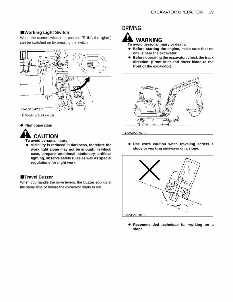
DRIVING
To avoid personal injury or death:A Before starting the engine, make sure that no
one is near the excavator.A Before operating the excavator, check the track
direction. (Front idler and dozer blade to thefront of the excavator).
A Use extra caution when traveling across aslope or working sideways on a slope.
A Recommended technique for working on aslope.
(1) Working light switch

EXCAVATOR OPERATION20
1. Adjust the engine speed from idling to an intermediatespeed.
2. Unlock the lock levers and pull in the bucket and holdthe bucket about 20 to 40cm above the ground.
3. Activate the dozer control lever to raise the dozer.
BDrive Levers(Right,Left)
To avoid personal injury or death:A If the swing frame has been turn 180deg, i.e. the
dozer in relation to the operator's seat is"behind", then the travel direction is oppositeto the drive direction of the levers (whenactivating the drive lever forwards, themachine, in relation to the operator's seat, willmove backwards).
Pushing the drive lever forwards, moves the excavatorforwards, and vice-versa. The front of the excavator is theside where the dozer is located; the drive sprocket is in therear of the excavator.
(1) Lock lever (A) "Unlock"
(A) 20 to 40 cm
(1) Dozer control lever (A) "Raise" (B) "Lower"
(A) "Raise" (B) "Lower"

21EXCAVATOR OPERATION
BTravel Speed Switch
To avoid personal injury:A When activating the travel speed switch, it
must be pushed down completely.
Travel speed will increase when this switch is pusheddown. Switching the dual travel speed:1. Press the travel speed switch. The buzzer beeps and
the travel speed changes from first speed to second.The symbol lights up.
2. Press the travel speed switch again, and the buzzerbeeps and the travel speed changes from secondspeed to first. The symbol light goes out.
A Each time the travel speed switch is pressed, thetravel speed is switched between first and second.
A Do not activate the travel speed switch when there isincreased drive resistance (e.g. driving on inclines oron uneven grounds).
A If the tracks are clogged with sand or gravel whileworking on soft ground, lift up both tracks with the helpof the boom, arm, dozer blade and bucket and let thetrack rotate to remove the sand and gravel.
(A) "Forward"(B) "Backward"(C) "Straight"
(1) Drive lever (left)(2) Drive lever (right)
(A) "Forward"(B) "Backward"
(1) Travel speed switch(2) Speed indicator light

EXCAVATOR OPERATION22
To avoid serious injury or death:A Do not work under the machine in this
condition.
TURNS
To avoid personal injury: A Do not change direction on steep slopes, or the
excavator could tip over.A Before changing direction, beware of people in
the work area.
BPivot Turn
A Movement as illustrated is done with the dozer bladein front of the operator.
When the dozer is in the back, the steering direction isreversed.(For example, push the left drive lever forward theexcavator turns right; the left track, seen from theoperator, will move backward from the operator.)
C Change of Direction while Travelling1. While travelling forwards, bring the left drive lever into
the neutral position;the excavator will turn to the left.
2. While travelling backwards, bring the left drive leverinto the neutral position; the excavator will turn to the right.
C Change of Direction while Stationary1. Push the left drive lever forward;
the excavator will turn to the right.
2. Pull the left drive lever backward; the excavator will turn to the left.
(A) "Rotate to remove sand and gravel"
(A) "Travelling forward" (N) "Neutral position"
(B) "Travelling backward" (N) "Neutral position"

23EXCAVATOR OPERATION
BSpin TurnWhen both drive levers are activated in the oppositedirections, both tracks will rotate with the same speed butin opposite directions. The center of rotation is the centerof the excavator.
UP AND DOWNHILL DRIVING
To avoid personal injury: A When traveling up or down a slope, use extra
caution and follow the instructions below.
While traveling uphill, keep the lower edge of the bucketapprox. 20 to 40cm above the ground. Although theKUBOTA excavator will not slip easily because of thetracks, it is safer to let the bucket slide over the groundwhile traveling downhill. Always choose slow speed foruphill and downhill traveling.
[UPHILL TRAVELING]
[DOWNHILL TRAVELING]
(A) "Left spin turn"
(B) "Right spin turn"
(A) 20 to 40 cm

EXCAVATOR OPERATION24
OPERATION OF THE DOZER1. To raise the dozer, pull back the control lever. Pushing
the control lever forwards, lowers the dozer.
2. While undertaking earth moving work, control bothdrive levers with the left hand and the dozer controllever with the right hand.
TWO PATTERN SELECTION SYSTEM(TPSS)
To avoid personal injury:A Study control lever pattern A and pattern B.
Then choose the one which is most familiarA Position the pattern selector lever (located on
the right side of operator's seat) in either thelower position (pattern A) or the upper position(pattern B).
A Engage the lock lever to prevent accidentalpattern change.
A Familiarize yourself with the pattern selectedby operating slowly.
BPattern Change1. Loosen the lock lever knob and slide it to the direction
(a), and position the pattern selector lever to thedesired position.
2. Slide the lock lever knob to the direction (b) and tightenit.
(1) Dozer control lever (A) "Raise"(B) "Lower"
(A) "Raise" (B) "Lower"
(1) Pattern selector lever (Two Pattern Selection System: TPSS)(2) Lock lever knob

25EXCAVATOR OPERATION
OPERATION OF THE BOOMTo raise the boom, pull the attachment control lever back. The boom is equipped with a cushion cylinder which helpsprevent excavated material in the bucket from falling out.Low hydraulic oil temperature, (e.g. after starting theengine in cold weather) the cushioning function will beeffected for a short period of time (approx. 3 to 5seconds). This condition results from the viscosity of thehydraulic oil and is not a sign of malfunction. The cushion cylinder will operate normally as the oilwarms up.
A When lowering the boom, make sure that it does nothit the dozer and that the bucket teeth do not touch thedozer.
Lever Position Pattern A Pattern B
Attachment Control Lever (Left)
A B C D
Boom down Boom up Swing left Swing right
Arm up Arm crowd Swing left Swing right
Attachment Control Lever (Right)
1 2 3 4
Arm up Arm crowd Bucket crowd Bucket dump
Boom down Boom up Bucket crowd Bucket dump

EXCAVATOR OPERATION26
OPERATION OF THE ARMPull back the attachment control lever and the arm will bepulled in. To move the arm out, push the control levertowards the front.
A When pulling in the arm, the movement may stop for ashort moment when the arm is in its vertical position.This is caused by the combined load of the arm andbucket moving the cylinder piston away from thehydraulic flow causing a delay in the cylinder action,until the flow catches up with cylinder piston. This is acharacteristic of the hydraulic system and is no sign ofa malfunction.
OPERATION OF THE BUCKETTo dig using the bucket, move the right attachment controllever from the neutral position, left. Moving the controllever right, moves the bucket outwards and empties itscontents.
27EXCAVATOR OPERATION
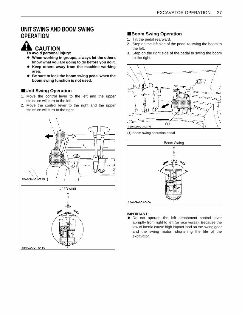
UNIT SWING AND BOOM SWING OPERATION
To avoid personal injury: A When working in groups, always let the others
know what you are going to do before you do it.A Keep others away from the machine working
area.A Be sure to lock the boom swing pedal when the
boom swing function is not used.
BUnit Swing Operation1. Move the control lever to the left and the upper
structure will turn to the left.2. Move the control lever to the right and the upper
structure will turn to the right.
BBoom Swing Operation1. Tilt the pedal rearward.2. Step on the left side of the pedal to swing the boom to
the left.3. Step on the right side of the pedal to swing the boom
to the right.
A Do not operate the left attachment control leverabruptly from right to left (or vice versa). Because thelow of inertia cause high impact load on the swing gearand the swing motor, shortening the life of theexcavator.
(1) Boom swing operation pedal

28 EXCAVATOR OPERATION
SERVICE PORT OPERATION
To avoid personal injury: A In the limited flow volume mode, be careful not to get the arm relieved. The service port will otherwise get fully
open.
A When the lock lever is raised, the service port activation switch is off.A Let the engine warm up after start-up for approx. 10 minutes under no load conditions.
BService Port OperationThis knob is used to operate hydraulic attachment such as breakers.

29EXCAVATOR OPERATION
C Usual settingsA Action mode of service port operationIt is possible to select from four action modes of the service port operation by pushing the service port activation switch.Each time the service port activation switch is pushed, the action mode changes from 1 through 4.
A When turning the starter key to the "RUN" position, the action mode will return to the last action mode used.
C Initial setting of limited service port flow volume (Make this setting first.)

30 EXCAVATOR OPERATION
A Setting of limited flow volumeMax. flow volume right and left can be adjusted in 15 stages independently.

31EXCAVATOR OPERATION
A Service Port Max. Flow Volume
Max. Flow Volume (Theoretical
L /min.)
KX91-3S2 63.0
U35-3S2 60.0
Max. Pressure MPa
(kgf/cm )
KX91-3S2 23.5 (240)
U35-3S2 24.5 (250)

32 EXCAVATOR OPERATION
A When the service port is not used for a long period, dirt particles can settle in the lower part of the service port lines. When the plugs on the service port lines are removed to connect attachments, drain approx. 100 cc (3.4 oz) of oil perside before making connections. For breaker choices, contact your dealer.
A Do not change the engine rpm using the limited flow volume setting. The service port speed will be otherwise lower, bywhich the attachment may get interrupted. In making the limited flow volume setting, find an optimum setting while varying the engine rpm.
A Suppose that the same attachment is mounted on another machine. Even if the same limit setting is made, the samespeed cannot be achieved. Make an optimum setting on each machine.
BOne Way Flow Operation

33EXCAVATOR OPERATION
1-way or 2-way CIRCUIT SELECTION VALVE OPERATIONA selection valve which selects 1-way or 2-way circuit ofservice port has been installed on the hydraulic tank.
1. When equipment which needs a 1-way circuit will beused, position the arrow, by using the supplied lever,on the axis of the selection valve to the 1-way circuitposition , to reduce the back pressure.
2. When equipment which needs a 2-way circuit will beused, position the arrow on the axis of the selectionvalve to the 2-way circuit position.
To avoid personal injury:A Stop the engine before removing/changing the
equipment.A Release pressure in the hydraulic system
before removing/chaging the equipment. (See"HOW TO RELEASE PRESSURE TRAPPED INTHE HYDRAULIC SYSTEM".)
A Position the selection valve to the correctposition (either 1-way or 2-way circuitselection) before mounting the equipment.
A Always select the correct valve position (1-wayor 2-way circuit selection) to avoid suddenmovement of the equipment.
A Leaving the selection valve to 1-way circuit selectionand attaching 2-way circuit equipment may cause theequipment to move (drop) suddenly due to its ownweight, as the tank line remains open, even with theengine off.
NOTE:A 1-way circuit..... HAMMER etc.
A 2-way circuit..... THUMB, TILT BUCKET, AUGER, GRAPPLE etc.

EXCAVATOR OPERATION34
AUTO IDLE (AI) OPERATION1. Throttle Potentiometer
With this potentiometer the operator can adjust theengine speed when the Auto Idle control is activated.
2. Switch for Auto Idle (AI) Control With this switch the Auto Idle control is turned on or off.The Auto Idle control allows the engine speed to dropto the engine speed preselected with thepotentiometer after about 4 seconds. If the controlactivated, the engine speed rises immediately to thepreset rpm. If the Auto Idle is not activated the throttlepotentiometer can be utilized to control engine speedsimilar way to a conventional throttle control lever.
A It is possible that the Auto Idle may not function untilhydraulic oil warms up in the cold weather. Thereforeit is not recommended that the Auto Idle be activateduntil the machine is completely warmed up.
A Before operating the control lever, check the Auto IdleIndicator Lamp.
A When operating in confined spaces or when loadingonto a vehicle, turn the Auto Idle switch off (Light off).This is to prevent unwanted engine speed increaseswhen control levers are activated.
A The Auto Idle control, when selected by a switch,provides the operator with a way to control enginespeed without a Throttle Potentiometer, simply by notactivating any control levers for about four secondsafter stopping work, and then to simply restore apreset (by potentiometer) engine speed by activatingany control lever to return to work.
A The purpose of system is to reduce fuel consumption,noise and operator fatigue.
IMPORTANT INFORMATION ON EXCAVATOR OPERATIONA Do not try to crush concrete or boulders using side
swings with the bucket. Also avoid using side sweepsof the bucket to move earth piles.
A Under all circumstances avoid the followingoperations:A Excavation using the gravitational impact of the
machine.A Compacting of gravel or soil using the dropping
action of the bucket.A Excavation using the traveling power of the
machine.A Do not try to drop or shake off soil adhering to the
bucket in the manner given in the points below. Thiscan cause damage to the machine. Adhering soil can be shaken off when the bucket isbeing emptied by moving the bucket out to themaximum stroke of the cylinder. Should this notsuffice, swing out the arm as far as possible andoperate the bucket back and forth.
A Do not hit the dozer with the boom cylinder! Make sure that the boom cylinder does not hit thedozer when doing deep excavation. If necessaryswing around so that the dozer is in the back of themachine.
A Pay attention when pulling in the bucket! When pulling in the bucket (for driving ortransportation) avoid hitting the dozer.
A Avoid collisions! When moving the excavator, pay attention that thedozer does not collide with obstructions such asboulders etc.. Such collisions shorten the life of the dozer and thecylinder substantially.
A Support the machine correctly! When stabilizing the machine with the dozer, lower thedozer to engage the full width on the ground.
A If the water or mud level reaches higher than the top ofthe tracks, the swivel bearing, swivel motor gear andring gear may be exposed to mud, water and otherforeign objects. The excavator must be properly pressure washedafter each use.A Thoroughly clean the area around the swivel
bearing, swivel motor gear and ring gear to removeforeign objects.
A Inspect the swivel motor oil sump (if equipped) forwater contamination. If water is present, refer tooperator's manual for lubricant replacementprocedure.
A Refer to operator's manual for proper swivelbearing, swivel motor gear and ring gearlubrication procedures.
A Reinstall any protective covering if removedearlier.
(1) Throttle potentiometer(2) Switch for Auto Idle control

35EXCAVATOR OPERATION
HOW TO RELEASE PRESSURE TRAPPED IN THE HYDRAULIC SYSTEMA Lower the attachments and the dozer blade to the
ground.A Turn the key to "STOP" position and shut off the
engine.A After stopping the engine, turn the key to "RUN"
position.A Release pressure in the hydraulic system by operating
levers with lever lock pulled down.
36 TRANSPORTING THE EXCAVATOR ON A VEHICLE
TRANSPORTING THE EXCAVATOR ON A VEHICLE
To avoid personal injury or death:A No directional changes should be made when
the excavator is on the ramp. Should a changeof direction be necessary, drive off the rampcompletely and make the turn.
A When driving forwards or backwards onto thevehicle, or when swinging the upper body,make sure that neither the CAB or the gates ofthe vehicle will be damaged.
A When the excavator reaches the point betweenthe ramps and the bed, halt and then move veryslowly until the excavator reaches thehorizontal position.
A Move the excavator onto the vehicle only withthe arm completely pulled in. Otherwise theCAB of the vehicle could be damaged whenswinging around the upper body.
A Do not jack up the machine using its boom toload or unload the excavator from the vehicle.Doing this is dangerous.
A Make sure the ramp are of sufficient capacityand securely connected to the vehicle to safetysupport the machine throughout the loading /unloading operation.
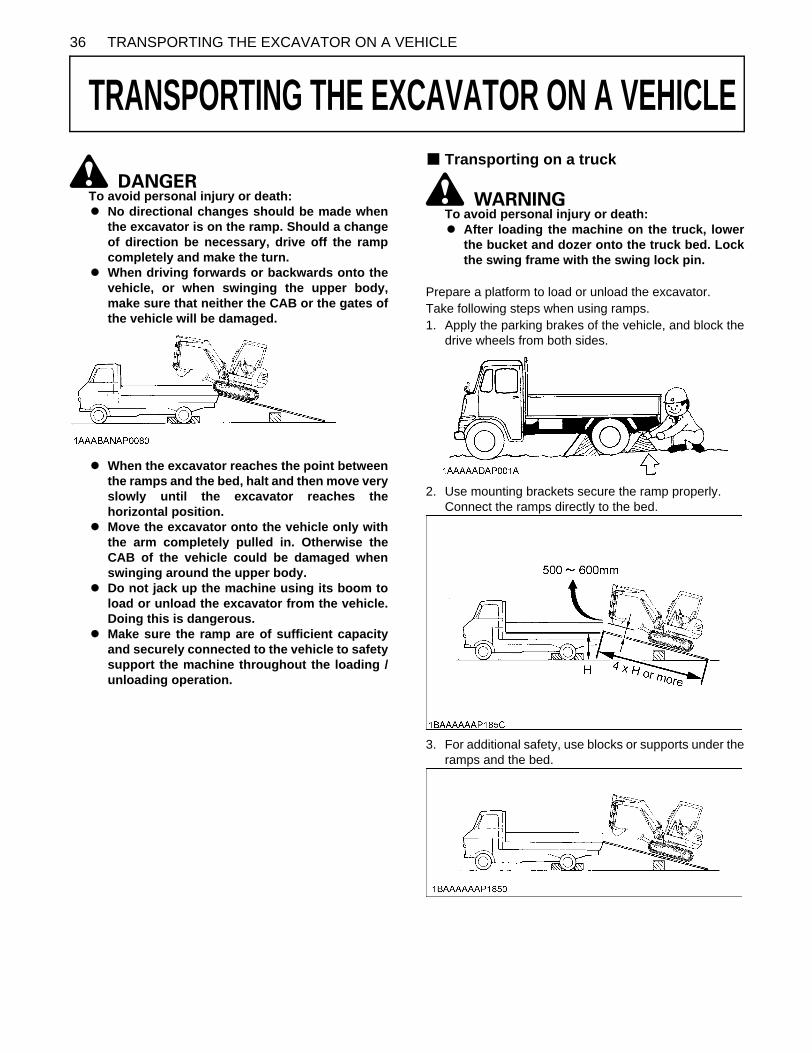
B Transporting on a truck
To avoid personal injury or death:A After loading the machine on the truck, lower
the bucket and dozer onto the truck bed. Lockthe swing frame with the swing lock pin.
Prepare a platform to load or unload the excavator. Take following steps when using ramps.1. Apply the parking brakes of the vehicle, and block the
drive wheels from both sides.
2. Use mounting brackets secure the ramp properly. Connect the ramps directly to the bed.
3. For additional safety, use blocks or supports under theramps and the bed.
37TRANSPORTING THE EXCAVATOR ON A VEHICLE
4. Completely align the ramps and the tracks and thendrive the excavator slowly up the ramps with the dozerin the front. After ensuring that the tracks arecompletely on the bed, swing the upper body aroundto the back of the vehicle.
5. Block the tracks and chain down the excavator withsuitable chains and approved method (checkappropriate state regulation).
6. Before unloading, raise the dozer and bucket from thebed.

38 LIFTING OF THE EXCAVATOR
LIFTING OF THE EXCAVATOR
To avoid serious injury or death:A The correct instructions for safe handling are
described here. Read these instructionscarefully before moving the machine. Makesure that the operating personnel read theoperator's manual carefully.
B Basics when Lifting with Cables or Straps1. The lifting and crane operation is to be undertaken
according to the safe operation guidelines described.2. The equipment used for lifting mentioned in these
instructions are only given as reference, the standardsconcerning strength, control and other details arebased on the respective applicable guidelines.
B Safety Aspects when Lifting with Cables or StrapsAbide by following steps when lifting:1. Do not lift loads that exceed the maximum load
capacity of the crane.2. Choose correct equipment suitable to the weight, size
and form of the load.3. First assess the center of gravity of the load, position
the hook directly over the load and lift the load so thatthe center of gravity of the load is as low as possible.
4. The steel cables or straps must be fixed in the middleof the hook.
5. The load must be lifted vertically from the ground. 6. Do not enter the working area under suspended loads
and do not move the load over people. The load mustonly be moved in an area where the balance can beeasily maintained.
B Lifting Procedure for the Excavator
To avoid personal injury or death:A Do not use the hooks on the roof of canopy and
CAB for lifting the excavator.
C General guidelines for lifting 1. Lifting position. (see the following illustration.)
(1) Pull in the boom completely towards the CAB.(2) Pull in the arm completely.(3) Pull in the bucket completely.(4) Adjust the swing angle to the center. (to bring the
boom in a position parallel to the machine frame)(5) Swing frame so that dozer blade is to the rear and
frame is parallel with tracks.(6) Raise the dozer blade fully.
2. Attaching the steel cables or straps.(1) Always hook the excavator at three points. (one
on the boom and left and right of the dozer)(2) Always use a shackle on each lifting hole when
attaching the cables or straps.(3) Using protective material at all places where the
cables or straps contact the machine.(4) Keep the angle between the front and rear cables
or straps within 60 (1.05 rad.).
To avoid personal injury or death:A Never lift the excavator by hooking the hole of
the boom only.
39LIFTING OF THE EXCAVATOR
3. Tackle The weights of the excavators and the recommendedtackle for lifting these loads are mentioned in thefollowing table. Choose components having enoughstrength.
*Excavator Weight: With CAB, steel tracks, and long arm. Steel cable: 6 x 24
4. Lifting(1) Lift slowly and safely(2) Do not enter the excavator area when lifting.(3) Lift the excavator horizontally. (Modify wire
connections according to needs)Maximum strength for example : (JIS G 35 25) - "6 x24"
1. Boom side Hook in the steel cable with a shackle into the liftinghole.
2. Dozer side Hook in the steel cable with a shackle into the liftinghole around the CAB or canopy.
3. Lifting
KX91-3S2 U35-3S2
Excavator Weight* kg 3330 3750
Load / Cable N(kgf)
12560 (1286)
11174 (1139)
Minimum Cable Diameter (Safety factor=6)
mm14
(9/16) or more
14 (9/16)
or more
Diameter zinc-plated not zinc-plated
10 mm (3/8)
KN (kgf)
45.8 (4670)
49.3 (5027)
12.5 mm (1/2)
KN (kgf)
71.5 (7291)
77 (7852)
14 mm (9/16)
KN (kgf)
89.7 (9147)
96.6 (9850)
16 mm (5/8)
KN (kgf)
117 (11931)
126 (12848)
18 mm (45/64)
KN (kgf)
148 (15092)
160 (16315)
(1) Steel cable(2) Shackle
(1) Steel cable(2) Shackle
(1) Protective material
40 MAINTENANCE
MAINTENANCE
MAINTENANCE INTERVALSNo. Check points MeasuresHour meter indicator
Interval Ref. page50 100 150 200 250 300 350 400 450
1 Coolantcheck Daily check 45
change every 2 years 59
2 Fuel check Daily check 45
3 Engine oilcheck Daily check 46
change every 250 hrs or every 1 year 54
4 Hydraulic oilcheck Daily check 46
change every 1000 hrs 57 *1
5 Lubrication points - Daily check 47
6 Radiator and oil cooler check Daily check 48
7 Washer liquid (CAB type) check Daily check 48
8 Engine and electrical wiring check Daily check 48
9 Fuel tank, Water separator drain every 50 hrs 49, 49
10 Battery condition check every 50 hrs 49
11 Greasing swing bearing teeth - every 50 hrs 51
12 Fan belt tension adjust every 200 hrs 51
13 Radiator hoses and clampscheck every 200 hrs 51
replace every 2 years 59
14 Air filter elementOuter element
clean every 200 hrs 52 *2
@replace every 1000 hrs 58 *2
Inner element replace every 1000 hrs 58 *2
15 Greasing swing ball bearings - every 200 hrs 53
16 Fuel filter cartridge replace every 500 hrs 56 @
17 Engine oil filter replace every 500 hrs or every 1 year 55
18 Drive unit oil change every 500 hrs 55
19 Hydraulic return filter element replace every 500 hrs 56
20 Hydraulic breather filter element replace every 1000 hrs 57
21 Hydraulic suction filter element replace every 1000 hrs 57
22 Filter in the pilot hydraulic system replace every 1000 hrs 58
23 Fuel injection nozzle injection pressure check every 1500 hrs 58 *4 @
24 Front idler and track roller oil change every 2000 hrs 58
25 Alternator and starter motor check every 2000 hrs 58
26 Injection pump check every 3000 hrs 59 *4 @
27 Radiator system rinse every 2 years 59
28 Fuel line and Intake air linecheck every 200 hrs 54
@replace every 2 years 60 *3
D 500 thru 1000 continued to the following table.

41MAINTENANCE
D The engine oil is gradually consumed and reduced with engine operation. The consumption depends on the type of joband the model of engine. Before operation, make sure that the oil level is between the upper and lower limits of the oillevel gauge. Add oil as required. To avoid a shortened service life or burn-out of the engine, use a Kubota-specified oiland genuine Kubota filter. Keep their specified replacement intervals in mind.
No. Check points MeasuresHour meter indicator
Interval Ref. page500 550 600 650 700 750 800 1000
1 Coolantcheck Daily check 45
change every 2 years 59
2 Fuel check Daily check 45
3 Engine oilcheck Daily check 46
change every 250 hrs or every 1 year 54
4 Hydraulic oilcheck Daily check 46
change every 1000 hrs 57 *1
5 Lubrication points - Daily check 47
6 Radiator and oil cooler check Daily check 48
7 Washer liquid (CAB type) check Daily check 48
8 Engine and electrical wiring check Daily check 48
9 Fuel tank, Water separator drain every 50 hrs 49, 49
10 Battery condition check every 50 hrs 49
11 Greasing swing bearing teeth - every 50 hrs 51
12 Fan belt tension adjust every 200 hrs 51
13 Radiator hoses and clampscheck every 200 hrs 51
replace every 2 years 59
14 Air filter elementOuter element
clean every 200 hrs 52 *2
@replace every 1000 hrs 58 *2
Inner element replace every 1000 hrs 58 *2
15 Greasing swing ball bearings - every 200 hrs 53
16 Fuel filter cartridge replace every 500 hrs 56 @
17 Engine oil filter replace every 500 hrs or every 1 year 55
18 Drive unit oil change every 500 hrs 55
19 Hydraulic return filter element replace every 500 hrs 56
20 Hydraulic breather filter element replace every 1000 hrs 57
21 Hydraulic suction filter element replace every 1000 hrs 57
22 Filter in the pilot hydraulic system replace every 1000 hrs 58
23 Fuel injection nozzle injection pressure check every 1500 hrs 58 *4 @
24 Front idler and track roller oil change every 2000 hrs 58
25 Alternator and starter motor check every 2000 hrs 58
26 Injection pump check every 3000 hrs 59 *4 @
27 Radiator system rinse every 2 years 59
28 Fuel line and Intake air linecheck every 200 hrs 54
@replace every 2 years 60 *3
42 MAINTENANCE
First operation*1 When using a hydraulic breaker, change hydraulic oil and return filter according to the table on "Hydraulic Oil Change(Including Exchange of the Suction Filter in the Hydraulic Tank) under "EVERY 1000 SERVICE HOURS" in the chapter"REGULAR CHECKS AND MAINTENANCE WORK".*2 Clean and replace the air filter more frequently if used under dusty conditions. When the filter is very dirty from dustyconditions, replace the filter.*3 Replace only if necessary. *4 Consult your local KUBOTA Dealer for this service.A The items listed above (@ marked) are registered as emission related critical parts by KUBOTA in the U.S.EPA non-
road emission regulation. As the engine owner, you are responsible for the performance of the requiredmaintenance on the engine according to the above instruction. Please see the Warranty Statement in detail.
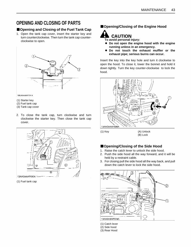
43MAINTENANCE
OPENING AND CLOSING OF PARTSBOpening and Closing of the Fuel Tank Cap1. Open the tank cap cover, insert the starter key and
turn counterclockwise. Then turn the tank cap counter-clockwise to open.
2. To close the tank cap, turn clockwise and turnclockwise the starter key. Then close the tank capcover.
BOpening/Closing of the Engine Hood
To avoid personal injury:A Do not open the engine hood with the engine
running unless in an emergency.A Do not touch the exhaust muffler or the
exhaust pipe; serious burns can occur.
Insert the key into the key hole and turn it clockwise toopen the hood. To close it, lower the bonnet and hold itdown tightly. Turn the key counter-clockwise to lock thehood.
BOpening/Closing of the Side Hood1. Raise the catch lever to unlock the side hood.2. Push the side hood all the way forward, and it will be
held by a restraint cable.3. For closing pull the side hood all the way back, and pull
down the catch lever to lock the side hood.
(1) Starter key(2) Fuel tank cap(3) Tank cap cover
(1) Fuel tank cap
(1) Key (A) Unlock(B) Lock
(1) Catch lever(2) Side hood(3) Rear Hood
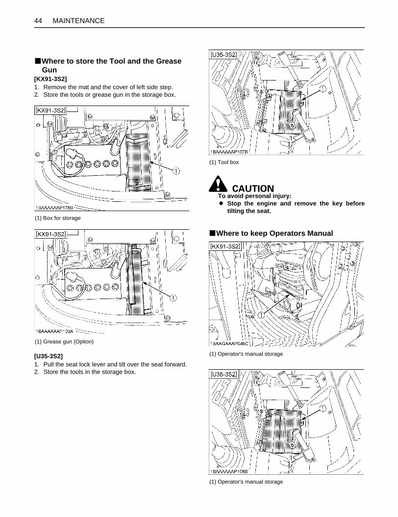
MAINTENANCE44
BWhere to store the Tool and the Grease Gun
[KX91-3S2]1. Remove the mat and the cover of left side step.2. Store the tools or grease gun in the storage box.
[U35-3S2]1. Pull the seat lock lever and tilt over the seat forward.2. Store the tools in the storage box.
To avoid personal injury:A Stop the engine and remove the key before
tilting the seat.
BWhere to keep Operators Manual
(1) Box for storage
(1) Grease gun (Option)
(1) Tool box
(1) Operator's manual storage
(1) Operator's manual storage
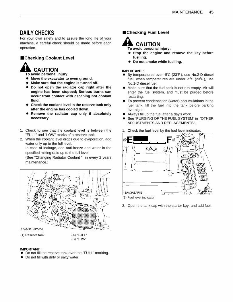
45MAINTENANCE
DAILY CHECKSFor your own safety and to assure the long life of yourmachine, a careful check should be made before eachoperation.
BChecking Coolant Level
To avoid personal injury:A Move the excavator to even ground.A Make sure that the engine is turned off.A Do not open the radiator cap right after the
engine has been stopped; Serious burns canoccur from contact with escaping hot coolantfluid.
A Check the coolant level in the reserve tank onlyafter the engine has cooled down.
A Remove the radiator cap only if absolutelynecessary.
1. Check to see that the coolant level is between the"FULL" and "LOW" marks of a reserve tank.
2. When the coolant level drops due to evaporation, addwater only up to the full level.In case of leakage, add anti-freeze and water in thespecified mixing ratio up to the full level.(See "Changing Radiator Coolant " in every 2 yearsmaintenance.)
A Do not fill the reserve tank over the "FULL" marking.A Do not fill with dirty or salty water.
BChecking Fuel Level
To avoid personal injury:A Stop the engine and remove the key before
fuelling.A Do not smoke while fuelling.
A By temperatures over -5 (23 ), use No.2-D dieselfuel, when temperatures are under -5 (23 ), useNo.1-D diesel fuel.
A Make sure that the fuel tank is not run empty. Air willenter the fuel system, and must be purged beforerestarting.
A To prevent condensation (water) accumulations in thefuel tank, fill the fuel into the tank before parkingovernight.
A Always fill up the fuel after a day's work.A See "PURGING OF THE FUEL SYSTEM" in "OTHER
ADJUSTMENTS AND REPLACEMENTS".
1. Check the fuel level by the fuel level indicator.
2. Open the tank cap with the starter key, and add fuel.
(1) Reserve tank (A) "FULL"(B) "LOW"
(1) Fuel level indicator

MAINTENANCE46
A See "Opening and Closing of the Fuel Tank Cap" and"LCD Display for Normal Operation."
BChecking Engine Oil Level
To avoid personal injury:A Stop the engine and remove the key before
checking the oil level.
Insert the engine oil dipstick fully into the respective portopening, remove again and check the oil level; ifnecessary fill with oil. The machine must be on levelground when checking the oil level.
A Use engine oil with the correct viscosity. (accordingthe outside temperature.)
A After stopping the engine and removing the key, waitfive minutes and then check oil level. The excavatormust be on level ground.
BChecking Hydraulic Oil Level
To avoid personal injury:A Stop the engine and remove the key before
checking the oil level.
A Before filling oil, wipe away all sand and dust fromaround the oil port. Make sure to use an identical typeof hydraulic fluid.
A The excavator has been filled with hydraulic fluidbefore delivery. See "RECOMMENDED OILS".(Do not mix different oils.)
1. Park the excavator on a firm, flat and level surface.Lower the attachments and dozer blade to the groundand stop the engine.
2. Check the oil level as to whether it lies on the center ofthe gauge at normal temperature (10 to 30 (50 to80 )).
3. Enough oil is present if the oil level lies near the centerof the gauge.
4. Should the oil level be too low, fill oil through the oilport before starting the engine. This step is importantfor the protection of the hydraulic system.
(1) Fuel tank cap
(1) Engine oil dipstick(2) Filling port
(A) Oil level is acceptable within this range.
(1) Tank cap (2) Gauge

47MAINTENANCE
BLubrication Points
To avoid personal injury:A First lower all attachments to the ground then
stop the engine and remove the key.A While greasing, take caution not to step on the
bucket teeth.A When doing excavation work in water,
generously grease the following points. Afterending work, grease again.
Grease the marked grease nipples shown by arrows in theillustration below.
1. Boom bottom linkage............................. 1 place
2. Arm bottom linkage................................ 1 place
3. Bucket link pin........................................ 4 places
4. Boom cylinder boss............................... 2 places
5. Arm cylinder boss.................................. 2 places
6. Bucket cylinder boss.............................. 1 place
7. Fixing pin between arm and bucket........ 1 place
8. Boom swing fulcrum.............................. 2 places
9. Swing cylinder boss............................... 1 place
10. Swing cylinder pin.................................. 1 place
11. Dozer cylinder boss............................... 2 places
12. Dozer linkage pin................................... 2 places

MAINTENANCE48
BChecking Radiator and Oil Cooler
To avoid personal injury:A Always stop the engine and remove the key
before checking the radiator.A Wear eye protection when cleaning with
compressed air.
1. Check if the fins and ribs are clogged.If so clean with compressed air or steam.
2. Check the rubber hoses for damage and replace ifcracked or old. Check if the hose clamps are tightenough.
A Radiator and oil cooler fins and ribs must be clean inorder not to overheat the engine and allow free flow ofair through the cooling elements.
BChecking Washer Liquid(only for CAB type)
If the windows washer is switched on with the washerliquid tank empty, the motor may be damaged. Alwayskeep the tank filled.
BChecking and Cleaning Engine and Electrical Wiring
To avoid personal injury:A Always stop the engine and remove the key
before cleaning the wiring, cables and engine.
Before starting, check whether flammable substanceshave gathered on the battery, the cables and wiring, themuffler or on the engine. Remove thoroughly.Check the electrical circuitry for disconnections, shorts orloose terminals.
BWashing Whole Machine
A Do not wash the excavator with the engine running.Water could enter the air filter and damage the engine.Make sure that the air filter is kept dry.
A Remove the mud before washing the machine.
(1) Radiator and oil cooler
(1) Washer liquid tank
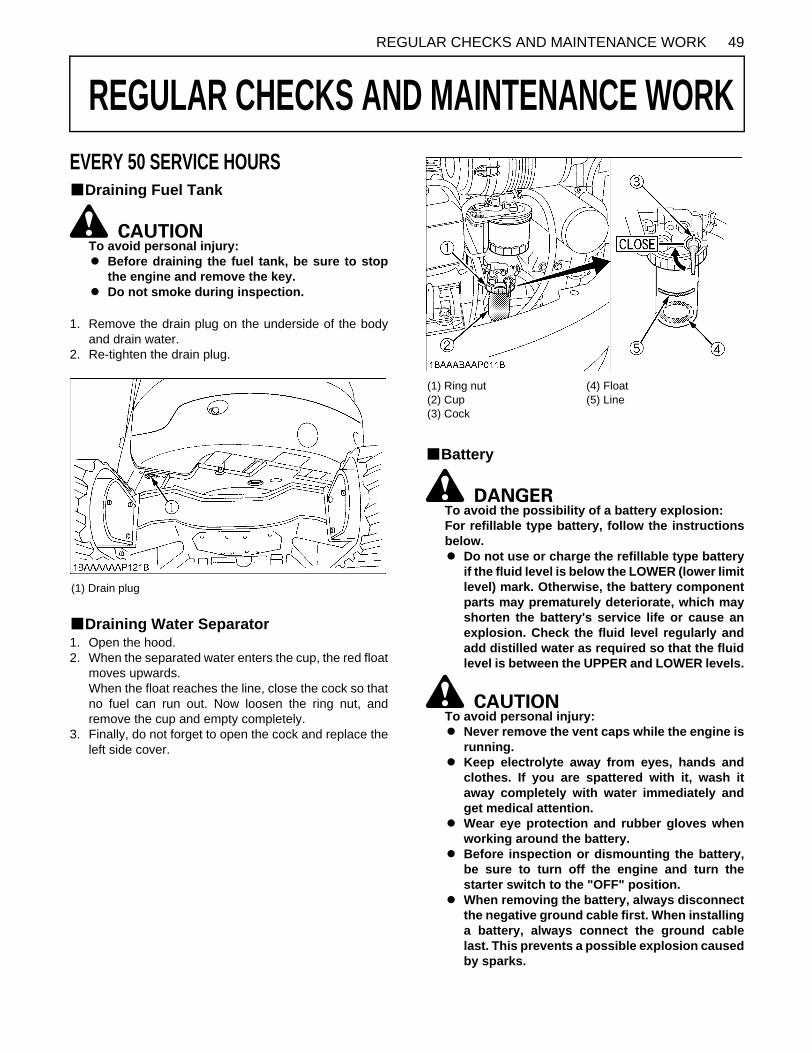
49REGULAR CHECKS AND MAINTENANCE WORK
REGULAR CHECKS AND MAINTENANCE WORK
EVERY 50 SERVICE HOURSBDraining Fuel TankTo avoid personal injury:A Before draining the fuel tank, be sure to stop
the engine and remove the key.A Do not smoke during inspection.
1. Remove the drain plug on the underside of the bodyand drain water.
2. Re-tighten the drain plug.
BDraining Water Separator1. Open the hood.2. When the separated water enters the cup, the red float
moves upwards. When the float reaches the line, close the cock so thatno fuel can run out. Now loosen the ring nut, andremove the cup and empty completely.
3. Finally, do not forget to open the cock and replace theleft side cover.
BBattery
To avoid the possibility of a battery explosion:For refillable type battery, follow the instructionsbelow.A Do not use or charge the refillable type battery
if the fluid level is below the LOWER (lower limitlevel) mark. Otherwise, the battery componentparts may prematurely deteriorate, which mayshorten the battery's service life or cause anexplosion. Check the fluid level regularly andadd distilled water as required so that the fluidlevel is between the UPPER and LOWER levels.
To avoid personal injury:A Never remove the vent caps while the engine is
running.A Keep electrolyte away from eyes, hands and
clothes. If you are spattered with it, wash itaway completely with water immediately andget medical attention.
A Wear eye protection and rubber gloves whenworking around the battery.
A Before inspection or dismounting the battery,be sure to turn off the engine and turn thestarter switch to the "OFF" position.
A When removing the battery, always disconnectthe negative ground cable first. When installinga battery, always connect the ground cablelast. This prevents a possible explosion causedby sparks.
(1) Drain plug
(1) Ring nut(2) Cup(3) Cock
(4) Float(5) Line
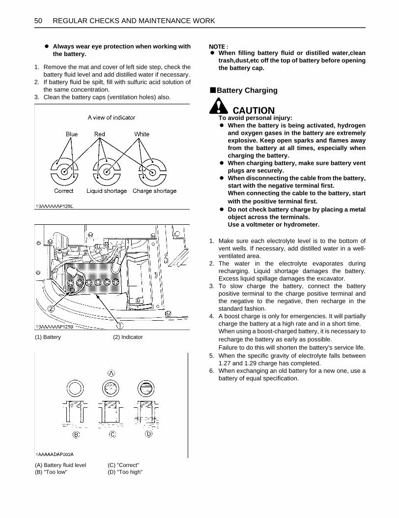
REGULAR CHECKS AND MAINTENANCE WORK50
A Always wear eye protection when working withthe battery.
1. Remove the mat and cover of left side step, check thebattery fluid level and add distilled water if necessary.
2. If battery fluid be spilt, fill with sulfuric acid solution ofthe same concentration.
3. Clean the battery caps (ventilation holes) also.
A When filling battery fluid or distilled water,cleantrash,dust,etc off the top of battery before openingthe battery cap.
BBattery Charging
To avoid personal injury:A When the battery is being activated, hydrogen
and oxygen gases in the battery are extremelyexplosive. Keep open sparks and flames awayfrom the battery at all times, especially whencharging the battery.
A When charging battery, make sure battery ventplugs are securely.
A When disconnecting the cable from the battery,start with the negative terminal first.When connecting the cable to the battery, startwith the positive terminal first.
A Do not check battery charge by placing a metalobject across the terminals.Use a voltmeter or hydrometer.
1. Make sure each electrolyte level is to the bottom ofvent wells. If necessary, add distilled water in a well-ventilated area.
2. The water in the electrolyte evaporates duringrecharging. Liquid shortage damages the battery.Excess liquid spillage damages the excavator.
3. To slow charge the battery, connect the batterypositive terminal to the charge positive terminal andthe negative to the negative, then recharge in thestandard fashion.
4. A boost charge is only for emergencies. It will partiallycharge the battery at a high rate and in a short time.When using a boost-charged battery, it is necessary torecharge the battery as early as possible.Failure to do this will shorten the battery's service life.
5. When the specific gravity of electrolyte falls between1.27 and 1.29 charge has completed.
6. When exchanging an old battery for a new one, use abattery of equal specification.
(1) Battery (2) Indicator
(A) Battery fluid level(B) "Too low"
(C) "Correct"(D) "Too high"

51REGULAR CHECKS AND MAINTENANCE WORK
BGreasing Swing Bearing Teeth1. Pump grease with grease gun through the grease
nipple (at the right end side).2. Grease at each 90 (1.58 rad.) position of the swing
frame.3. Fill with approx. 50g of grease (approx. 20 to 30
pumps with the grease gun at each position).
EVERY 200 SERVICE HOURSDo all 50-hour servicing at the same time.
BChecking Fan Belt TensionC Check and adjustment of the fan belt tension
To avoid personal injury:A First stop the engine and remove the key.A After servicing, make sure to replace the belt
cover in its original position.
1. Press the fan belt down in the middle, with a force ofapprox. 7 kg. The belt tension is correct if it deflectsabout 8 mm. If otherwise, loosen bolt (1) shift thealternator (2) in the direction shown by the arrow.
2. Replace the fan belt if worn out, cracked or torn.
A If the engine is run with a loose fan belt, the belt couldslip and cause overheating of the engine or insufficientbattery charging. Check fan belt tension regularly.
A Should the fan belt break or jump off, the indicator lightfor battery charge will light up. Stop the engine andremove the key immediately.
BChecking Radiator Hoses and Clamps
To avoid personal injury:A Wait long enough for the radiator coolant to
cool down.
Check the water hoses for proper connection. This checkshould be carried out every 200 hours or every 6 months,whichever comes first.1. Should the hose clamps become loose or water leaks,
tighten the hose clamps properly.2. Should the radiator hoses become swollen, aged or
cracked, they must be replaced and the hose clampstightened again properly.
(1) Grease nipple
(1) Bolt(2) Alternator

REGULAR CHECKS AND MAINTENANCE WORK52
BInspection and Cleaning Air Filter ElementOpen the engine cover and remove the dust cover. Takeout only outer element, clean the element, case interiorand reassemble. During reassembly, take care to installthe dust cover with facing the TOP mark upwards. Do notremove the inner element (safety element).
A Should the machine be used in extreme dusty areas,the air filter element must be inspected and cleanedmore frequently than in the specified maintenanceperiods.
A The air filter has a dry element, keep free from oil.A Do not run the engine without the air filter.
(1) Radiator hoses (2) Hose clamps
(1) Radiator hoses (2) Hose clamps(1) Outer element(2) Inner element (safety element)(3) Case(4) Dust cover(5) Clamps

53REGULAR CHECKS AND MAINTENANCE WORK
BAir Filter Maintenance
To avoid personal injury:A Wear eye protection.
The quickest and safest method of maintenance is theexchange of the paper cartridge. Furthermore there aredifferent methods of cleaning the cartridge.
C Cleaning with compressed airPressure of compressed air must be under 205 kPa (2.1kgf/ ), and the cartridge should be blown clean from theinside to the outside until the dust deposits are noticeablyreduced.
A If the air suction is still inadequate, or the color of theexhaust gases is abnormal even after the cleaning, theair filter cartridge must be replaced.
BGreasing Swing Bearing1. Fill with grease through the respective grease nipple.2. Grease at each 90 (1.58 rad.) position of the swing
frame.
(1) Grease nipple

REGULAR CHECKS AND MAINTENANCE WORK54
BChecking Fuel Line and Intake Air Line1. Check to see that all lines and hose clamps are
tightened and not damaged.2. If hoses and clamps are found worn or damaged,
replace or repair them at once.
EVERY 250 SERVICE HOURSDo all 50 hour servicing at the same time.
BChanging Engine Oil(First Engine Oil Change after 50 Service Hours)
To avoid personal injury:A First stop the engine then remove the key and
wait long enough for the oil to cool down.
1. Remove the drain plug on the underside of the engineand drain all oil.
2. Re-tighten the drain plug.
3. Fill through the filling port up the specified level.
4. Let the engine idle for approx. 5 min. Check the engineoil level. To check the engine oil level, insert theengine oil dipstick completely into the respective portopening and pull out again. If the oil level lies betweenboth markings, no oil must be added.
(1) Fuel lines(2) Clamp bands
(1) Hoses(2) Hose clamps
(1) Drain plug
(1) Oil filling port

55REGULAR CHECKS AND MAINTENANCE WORK
A Regardless of the service hours, an engine oil changeis due every six months.
EVERY 500 SERVICE HOURSDo all 50 and 250 hour servicing at the same time.
BReplacing Engine Oil Filter(Replace the engine oil filter every 500 hours,or every 1 year in the case that service hour is less than 500 hours)
1. Replace the oil filter cartridge at the same time asdoing the engine oil change.
2. Remove the cartridge with the supplied filter wrench.
3. Oil the O-ring of the new oil filter cartridge lightly. Thentighten the oil filter cartridge by hand.
4. Fill engine oil to the specified level.5. Let the engine run for approx. 5 min. and make sure
that the engine oil indicator lamp does not light up.Then stop the engine and remove the key.
6. The engine oil level is reduced by the amount of thefilter capacity after the engine is started. It is necessaryto add oil.
A Always check the oil level after having exchanged thefilter.
BDrive unit Oil Change(First Oil Change at 100 hours)
To avoid personal injury:A Lower to the ground, stop the engine and
remove the key before undertaking the oilchange.
1. Rotate the track so that the drain plug of the drive unitis in the bottom position.
2. Remove the drain plug to let the oil run out. Screw inand tighten the drain plug again and fill with gear oilthrough the oil check port.
3. Fill oil until it overflows out of the oil check port.
Oil change- first oil change after 100 hrs- then every 500 hrs - or at least once a year
4. Use prescribed gear oil SAE 90.
(1) Oil filter
Engine oil volumes (with engine oil filter) 5.9 L
(1) Oil check port(2) Drain plug(3) Oil filling port
Gear oil volume approx. 0.6 L

REGULAR CHECKS AND MAINTENANCE WORK56
BReplacing Fuel Filter Cartridge
To avoid personal injury:A Keep fire away.
1. Remove the filter with the supplied filter wrench.2. Add fuel to a new filter before installing.3. Apply a light film of fuel to the seal of the new filter and
turn in tightly by hand.4. Open the cock of the fuel filter again.
A After exchange of the filter, the fuel system must bepurged of air.
BReplacing Hydraulic Return Filter Element(first replacement after 250 service hours)
To avoid personal injury:A Remove the oil filter only after the oil in the
hydraulic tank has cooled down.
1. Remove the cover of the hydraulic tank.2. Pull out the filter support by the top plate from the
hydraulic tank.3. Remove the return filter from the filter support with a
fork wrench and exchange the filter.
A Always check the oil level when replacing the filter.
(1) Fuel filter cartridge
(1) Set bolt(2) Filter support
(3) Return filter(4) Cover

57REGULAR CHECKS AND MAINTENANCE WORK
EVERY 1000 SERVICE HOURSDo all 50, 100, 200, 250 and 500 hour servicing at thesame time.
BHydraulic Oil Check for Machines with Hydraulic Breakers
The hydraulic oil change after 1000 operating hours in theoperator's manual is based on the type of work done.Following inspection measures are valid when hydraulicbreakers are used:1. Changing and filling up of hydraulic oil
(1) The hydraulic oil must be changed more oftenwhen breakers are used because the machine issubject to harder conditions than normalexcavating work.
(2) Use only the recommended oils mentioned in theoperator's manual when changing or filling withoil.
(3) When filling up oil, never mix oils of differentmakes.
2. Changing the return filter and oil(1) The filter must be changed more often because of
contamination resulting from the frequentassembly and disassembly of the hoses.
(2) Use the correct replacement filter. (3) Oil change according to operating hours.
BHydraulic Oil Change(Including Replacing Suction Filter and Breather Filter Element in Hydraulic Tank)
To avoid personal injury:A Wait long enough for the hydraulic fluid to cool
down. Then begin with the change of thehydraulic fluid.
1. Park the excavator on a firm, flat and level surface.Lower the attachments and dozer blade to the groundand stop the engine.
2. Remove the drain plug on the underside of thehydraulic tank and drain the oil.
3. Remove the cover of the hydraulic tank.4. With a fork wrench or similar, remove and replace the
filter with new one.5. Retighten the drain plug, and remove iron powder
adhering to the magnet.
�������� ��� � ���� ���� � ������ ���� �
������ ������� ����
�� �� �
����
�������
���
���
���
��� � ��
!��
� �� "���
��#$
��� !�� ��#$
��� ��� ��#$
��� %�� ��#$
��� ��� ��#$
&����#$
'�&���#$ �(� �
(��#� �� ������
%�� ��#$
"�� ��#$
"��� ��#$
(1) Set bolt(2) Filter support(3) Return filter(4) Cover
(5) Suction filter(6) Drain plug(7) Bolt(8) Breather filter

REGULAR CHECKS AND MAINTENANCE WORK58
6. Fill oil through the oil filling opening on the top side ofthe tank.
7. Let the engine run for approx. 5 min. and check the oillevel again.
A Should dirt deposits be in the hydraulic tank, removewith the help of a clean cloth and light oil.
BReplacing Hydraulic Pilot Filter Element
To avoid personal injury:A Before replacing the element, wait long enough
for the hydraulic fluid to cool down.
1. Remove the arch cover.2. Remove the hydraulic oil tank cover.3. Remove the pilot filter case from the head cover.4. Wrench and pull out the element downward.5. Replace the O-ring with a new one.6. Apply a light coating of clean hydraulic oil to the O-ring
and fit it to the case firmly. Be careful not to scratch theO-ring.
7. Install the case to the head cover firmly.8. Let the engine run for approx. 3 minutes.9. Check the oil level of hydraulic oil tank.
EVERY 1000 SERVICE HOURS OR ONCE A YEARBReplacing Air Filter ElementOpen the engine cover and remove the dust cover.Take out outer element and inner element (safetyelement).Replace inner and outer element.Installing the dust cover, be sure to its TOP mark (arrow)faces upwards.
A Shorten the replacement period if using in a placeexposed to lots of dust or sandy areas.
EVERY 1500 SERVICE HOURSBChecking Fuel Injection Nozzle(Injection
Pressure)Consult your local KUBOTA Dealer for this service.
EVERY 2000 SERVICE HOURSDo all 50, 200, 250, 500 and 1000 hour servicing at thesame time.
BChanging Front Idler and Track Roller Oil
A Contact your KUBOTA dealer for details.
BChecking Alternator and Starter Motor
A Contact your KUBOTA dealer for details.
Hydraulic oil volumes 55 L
(1) Head cover(2) Element(3) O-ring(4) Case
(1) Outer element(2) Inner element (Safety element)(3) Case(4) Dust cover(5) Clamps

59REGULAR CHECKS AND MAINTENANCE WORK
EVERY 3000 SERVICE HOURSBChecking Injection PumpConsult your local KUBOTA Dealer for this service.
ANNUAL SERVICEBElectrical Wiring and FusesCheck the terminals periodically for proper connections.Loose wiring or damaged cables can cause improperfunctioning or short circuiting of the electrical system.Check wiring and replace damaged componentsimmediately. If a fuse blows out soon after having beenreplaced, contact your nearest KUBOTA dealer. Do notuse a fuse other than specified.
BIENNIAL SERVICING
To avoid personal injury:A Do not loosen the radiator cap before the
radiator has cooled down sufficiently. Thenonly loosen the cap and allow enough time forthe pressure in the system to be released. Nowremove the cap completely.
BReplacing of Radiator HosesReplace radiator hoses and hose clamps every two years.If the hoses are swollen, hard or cracked, they must bereplaced earlier.
BChanging Radiator Coolant
To avoid personal injury:A When using anti-freeze, put on some protection
such as rubber gloves (Anti-freeze containspoison.).
A If anti-freeze has been swallowed, seek medicalattention at once.
A When anti-freeze comes in contact with theskin or clothing, wash it off immediately.
A Do not mix different types of Anti-freeze. Themixture can produce chemical reactioncausing harmful substances.
A Anti-freeze is extremely flammable andexplosive under certain conditions. Keep fireand children away from anti-freeze.
A When draining fluids from the engine, placesome container underneath the engine body.
A Do not pour waste onto the grounds, down adrain, or into any water source.
A Also, observe the relevant environmentalprotection regulations when disposing of anti-freeze.
A Anti-freeze if swallowed is poison to people,animals and birds.
Stop the engine then remove the key and wait until it hascooled down completely.1. Open the drain plug on the bottom of the radiator and
drain coolant completely, Should a reserve tank beequipped, disconnect the line from the tank floor andthen open the drain cock.
2. To clean, rinse the radiator with water.3. Close the drain plug and fill the radiator and the
reserve tank with coolant fluid. Let the engine idle forabout 5 min., stop the engine and remove the key thencheck the coolant level.
(1) Radiator hoses(2) Hose clamps
(1) Radiator hoses(2) Hose clamps

REGULAR CHECKS AND MAINTENANCE WORK60
4. The machine has been shipped filled with 50% anti-freeze solution.
A Do not operate the engine without coolant.
A To fill the radiator system and the reserve tank, usefresh water and anti-freeze fluid.
A When the anti-freeze is mixed with water, the anti-freeze mixing ratio must be less than 50%
A Tighten the radiator cap properly. If the cap is looselyor not properly fitted, overheating of the engine canresult due to coolant fluid loss.
BReplacing Fuel HoseReplace the hoses and clamps.(See "Checking Fuel and Intake Air Line" every 200 hoursmaintenance.)
BReplacing Intake Air lineReplace the hoses and clamps, if necessary.(See "Checking Fuel and Intake Air Line" every 200 hoursmaintenance.)
(1) Drain plug
(1) Radiator cap
(2) Reserve tank (A) Full(B) Low
Radiator approx. 4.0 L
Reserve tank approx. 1.6 L
(1) Fuel lines(2) Clamp bands
(1) Hoses(2) Hose clamps

61OTHER ADJUSTMENTS AND REPLACEMENTS
OTHER ADJUSTMENTS AND REPLACEMENTS
PURGING FUEL SYSTEM1. Fill up the excavator with fuel.2. Turn the starter key to the position "RUN".3. The air in the fuel system will automatically be purgedwithin one minute.
A If the purging was insufficient, the engine dies rightafter starting. In this case repeat steps (2) to (3) again.
ADJUSTMENT OF TRACKSBRubber TracksTension the tracks as specified:1. Loosen the bolt (1) and remove the cover (2).2. Apply grease (4) to the grease nipple (3).
3. Tension the track in the lifted position, so that thedistance "A" (clearance between the center track rollerand the track surface of the track) is 10 to 15 mm (seeillustration) In this case, the track seam is positionedon the top center between the idler and the sprocket.
To avoid serious injury or death:A Do not work under the machine in this
condition.A For your safety do not rely on hydraulically
supported devices, they may leak down andsuddenly drop or be accidentally lowered.
(1) Starter switch (A) "STOP"(B) "RUN"(C) "START"
(1) Bolt(2) Cover
(3) Grease nipple(4) Grease gun (Option)
(1) Seam (Mark " ")
(A) 10 to 15 mm
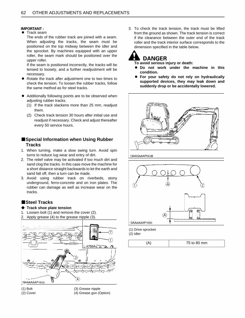
OTHER ADJUSTMENTS AND REPLACEMENTS62
A Track seam The ends of the rubber track are joined with a seam.When adjusting the tracks, the seam must bepositioned on the top midway between the idler andthe sprocket. By machines equipped with an upperroller, the seam mark should be positioned over theupper roller. If the seam is positioned incorrectly, the tracks will betensed to loosely, and a further readjustment will benecessary.
A Rotate the track after adjustment one to two times tocheck the tension. To loosen the rubber tracks, followthe same method as for steel tracks.
A Additionally following points are to be observed whenadjusting rubber tracks.(1) If the track slackens more than 25 mm, readjust
them.(2) Check track tension 30 hours after initial use and
readjust if necessary. Check and adjust thereafterevery 50 service hours.
BSpecial Information when Using Rubber Tracks
1. When turning, make a slow swing turn. Avoid spinturns to reduce lug wear and entry of dirt.
2. The relief valve may be activated if too much dirt andsand clog the tracks. In this case move the machine fora short distance straight backwards to let the earth andsand fall off, then a turn can be made.
3. Avoid using rubber track on riverbeds, stonyunderground, ferro-concrete and on iron plates. Therubber can damage as well as increase wear on thetracks.
BSteel TracksC Track shoe plate tension1. Loosen bolt (1) and remove the cover (2).2. Apply grease (4) to the grease nipple (3).
3. To check the track tension, the track must be liftedfrom the ground as shown. The track tension is correctif the clearance between the outer end of the trackroller and the track interior surface corresponds to thedimension specified in the table below.
To avoid serious injury or death:A Do not work under the machine in this
condition.A For your safety do not rely on hydraulically
supported devices, they may leak down andsuddenly drop or be accidentally lowered.
(1) Bolt(2) Cover
(3) Grease nipple(4) Grease gun (Option)
(1) Drive sprocket(2) Idler
(A) 75 to 80 mm

63OTHER ADJUSTMENTS AND REPLACEMENTS
C To loosen the tracks, follow following procedure:
To avoid personal injury:A Do not loosen the grease nipple completely or
too quickly. Otherwise grease under highpressure in the tension cylinder could squirtout.
A Make sure that no obstacles, such as stonesare caught in the track. Remove such obstaclesbefore adjusting the track tension.
1. Loosen the bolt of the cover and remove the cover.2. Using a socket wrench, loosen the grease nipple a few
turns.3. When grease oozes out from the thread, rotate the
track and loosen the track in the lifted position (seeillustration).
After adjustment is completed:Using the socket wrench, tighten the grease nipple.Tightening torque must be between 1000 to 1100 kgf-cm.
A If the tracks are too tight, wear is increased.A If the tracks are too loose, the track pads may collide
with the sprocket, wear is increased. The track may dislocate or come off.
A Clean the track after every use.A Should the track tension be high due to sticking mud,
lift the track with the help of the boom, arm and bucket,idle the engine and remove mud from the track,especially from the openings of the link plate carefully.
CHANGING THE BUCKET
To avoid personal injury:A When the coupling pins are removed or
installed, chips may come off. Always usegloves, goggles and a helmet.
A When the change of the equipment must beperformed with the engine running, alwayswork as a 2-person team. One person sits in the operator's seat and theother works on the machine.
A Do not use your fingers to center the holes,since they may be injured or even cut in case ofsudden or uncontrolled movements.
A Read the manual of the attachment to do acorrect operation safely when otherattachments are installed instead of Kubotaspecified bucket.
FUSES
To avoid personal injury:A When changing fuse, stop the engine and turn
the key in position "STOP".
BReplacing Fuses1. Remove the cover of the fuse box.2. Replace the burnt out fuse with a fuse having the same
capacity.
BFuse Capacities and Circuits
5A Room Light 10A Heater Fan
20A Work Light 15A AI Motor
5A Meter Sub
10A Alternator
5A Lock Lever
10A Horn
15A Cigarette Lighter 10A Meter Main
15A Auxiliary 5A Travel Hi-Low
15A Wiper / Washer 5A Relay Source

OTHER ADJUSTMENTS AND REPLACEMENTS64
BAuxiliary ElectricMax power is less than 110 W including the equipped light55 W.
BSlow Blow FuseSlow blow fuse is provided to protect the electrical circuits.If the fusible link is blown, check the electrical circuits fortrouble and then replace with a new compatible slow blowfuse.
(1) Fuse box(2) Auxiliary electric A
(1) Fuse box(2) Auxiliary electric A
(1) Slow blow fuse (50 A)
(1) Slow blow fuse (60 A)

65TROUBLESHOOTING
TROUBLESHOOTING
If the mini-excavator does not show the desired performance, or when trouble arises, refer to the table below and undertakeappropriate measures.Trouble Cause Countermeasure
Engine
Starting difficulties
Lock levers in "UNLOCK" position * Bring lock lever into "LOCK" position.
Fuel is too viscous.* Check fuel tank and filter. * Remove impurities and water. * If necessary, replace filter.
Air or water in the fuel system
* Remove water from the fuel tank. * Check fuel pipe joint bolts and nuts for looseness. * Purging of the fuel system (for fuel filter and injection pump, see "PURGING FUEL SYSTEM" in the chapter. "OTHER ADJUSTMENTS AND REPLACEMENTS".)
Oil viscosity is so high that the engine runs sluggishly in winter.
* Pour hot water over the radiator.
Battery is almost dead; insufficient compression. * Recharge battery.
Insufficient engine power
Low fuel level * Check fuel and add if necessary.
Clogged air cleaner * Clean the air filter element.
Engine suddenly stops. Low fuel level * Check fuel and add if necessary.
* Purge the fuel system.
Abnormal exhaust gas color
Poor fuel * Use high quality fuel.
Too much engine oil * Drain engine oil to prescribed oil level.
Water temperature in red zone (Overheating)
Defective seal of the water pump * Replace.
Worn or torn fan belt * Adjust or replace.
Thermostat is defect. * Replace.
Coolant level too low * Fill to prescribed level.
Radiator grill or fins are clogged. * Clean.
Coolant is contaminated with rust from the cylinder head or crank case.
* Replace coolant fluid and add anti-rust.
Defective radiator cap (Evaporation) * Replace.
Corroded coolant pipes * Clean.
Continuous operation under full load * Reduce load.
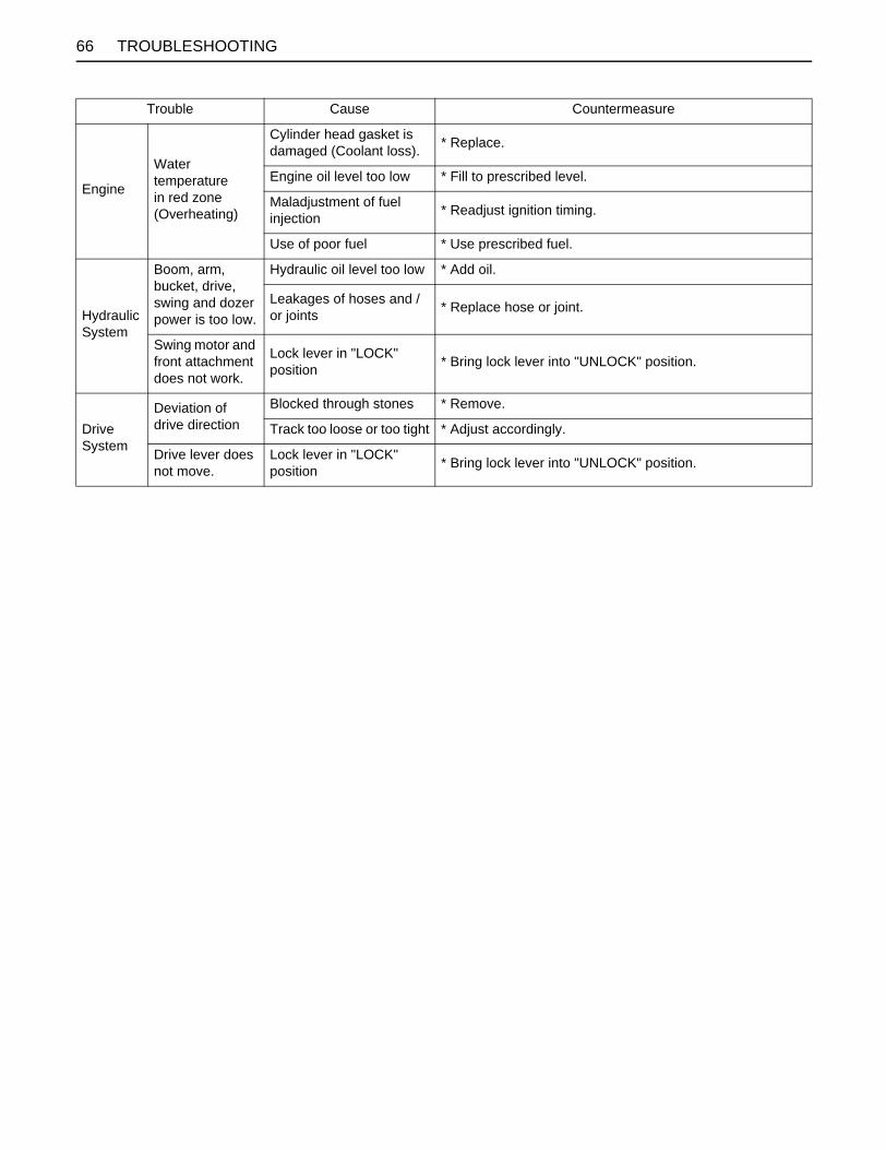
66 TROUBLESHOOTING
Engine
Water temperature in red zone (Overheating)
Cylinder head gasket is damaged (Coolant loss). * Replace.
Engine oil level too low * Fill to prescribed level.
Maladjustment of fuel injection * Readjust ignition timing.
Use of poor fuel * Use prescribed fuel.
Hydraulic System
Boom, arm, bucket, drive, swing and dozer power is too low.
Hydraulic oil level too low * Add oil.
Leakages of hoses and / or joints * Replace hose or joint.
Swing motor and front attachment does not work.
Lock lever in "LOCK" position * Bring lock lever into "UNLOCK" position.
Drive System
Deviation of drive direction
Blocked through stones * Remove.
Track too loose or too tight * Adjust accordingly.
Drive lever does not move.
Lock lever in "LOCK" position * Bring lock lever into "UNLOCK" position.
Trouble Cause Countermeasure

67TROUBLESHOOTING
KUBOTA I.C.S. NAVIGATION LIST OF MESSAGESIf an error occurs with the machine, one of the following messages appears in the LCD display.In case of a trouble, immediately contact your local dealer for inspection and repair.
Message Warning lamp Color
Problem or failure (what happened)
Machine behavior (provisional measure) Correction
yellow Fuel running out. - Add fuel.
redEngine oil circuit error (clogged) or engine oil shortage.
Immediately stop the engine.
The engine may be seized, failing to restart the engine. Immediately contact your local dealer for repair.
red Charging line in trouble. Charging failure.
Check the fan belt. (When the belt is in good condition, keep running until the battery becomes dead.)
Immediately contact your local dealer for repair.
red 24V line engine startup alternator defective.
[Do not start the engine on 24V line. Get it restarted to see if there is the message again.]
If the message does not reappear, no repair is needed. If the message stays on, contact your local dealer for repair.
yellowThe engine has been started with the lock lever down.
The engine fails to start.
Pull up the lock lever and start the engine.
yellow
The hour meter has reached the specified count-up. Carry out the maintenance job.
-Carry out the specified maintenance job.
No message (warning lamp flashing) red Sensor power line short
circuited.The work light lights up.
Immediately contact your local dealer for repair.

68 TROUBLESHOOTING
C Service hour meterWhen the hour meter has counted up to the hours circled in the maintenance list below, the message appears. Themessage shows up as follows.
The message appears. The message shows up as follows.
(The message reappears on the hour meter designated next.)
A The maintenance message disappears automatically in about 10 seconds.A When the key is turned from OFF to RUN, the maintenance message reappears and disappears again automatically in
about 10 seconds.A When the key is turned from OFF to RUN repeatedly 10 times, the message disappears.
C In case the service hour meter replaced due to any trouble with it, the meter is set to "0". Contact your KUBOTA dealerfor details.
No. Check points MeasuresHour meter indicator
Interval50 100 250 300 500 550 600 750 800 1000
1 Engine oilchange
every 250 hrs or every 1 year
2 Hydraulic oil every 1000 hrs
3 Air filter element
Outer element
replaceevery 1000 hrs
Inner element every 1000 hrs
4 Drive unit oil change every 500 hrs
5 Engine oil filter
replace
every 500 hrs or every 1 year
6 Hydraulic return filter element every 500 hrs
7 Hydraulic breather filter element every 1000 hrs
8 Hydraulic suction filter element every 1000 hrs
First operation

69OPERATION UNDER COLD WEATHER CONDITIONS
OPERATION UNDER COLD WEATHER CONDITIONS
PREPARATION FOR OPERATION IN COLD WEATHER1. Replace engine oil and hydraulic oil with those ofviscosities suitable for cold weather.2. In cold weather, battery power drops, and the battery
fluid may freeze if the battery is not sufficientlycharged. To prevent the battery fluid from freezing, besure to keep the battery charged at least 75% or moreof its capacity after operation. To ease next starting, itis recommended to keep the battery stored in closedor heated rooms. If the battery fluid level is too low, donot add after operation, but add with the enginerunning before the next operation.
3. Add anti-freeze to coolant in the radiator and reservetank, if the ambient temperature is expected to dropbelow 0 (32 ). Mixing ratio of water and anti-freezedepends on the expected ambient temperature.
A Mixing ratio between water and anti-freeze
A Use permanent anti-freeze or long-life coolant.A Drain the coolant completely and clean the inside of
the radiator, then fill with the water and anti-freezemixture.
A The anti-freeze acts as an anti-corrosive, it is notnecessary to add an additive to the water and anti-freeze mixture.
A See "Coolant check" under "DAILY CHECKS" in"MAINTENANCE" for radiator fill volumes.
PROCEDURE AFTER DONE WORKClean the excavator thoroughly after work and wipe dry.Otherwise mud and earth on the tracks could freeze if thetemperature drops below the 0 (32 ) mark. Operationof the excavator is then not possible. Store the excavatorin a dry place; if not possible, store on wooden planks oron mats. If the excavator is kept on damp or muddyground, the tracks could freeze overnight. Operation ofthe excavator is then not possible. Furthermore thereduction gear may be damaged.Additionally, the piston rods of the hydraulic cylindersmust be rubbed dry. Otherwise severe damage couldoccur if dirty water seeps through the seals.
Ambient Temperature
( )
-5 (+23)
-10 (+14)
-15 (+5)
-20 (-4)
-25 (-13)
-30 (-22)
-35 (-31)
Antifreeze % 30 30 30 35 40 45 50
Water % 70 70 70 65 60 55 50

70 LONG STORAGE
LONG STORAGE
To avoid personal injury:A Do not clean the excavator with the engine running.A To avoid the danger of exhaust fume poisoning, do not operate the engine in a closed building without
proper ventilation.A When storing, remove the key from the starter switch to avoid unauthorized persons from operating the
excavator and getting injured.
B Should the Excavator be Stored for a Longer Period of Time, Observe Following Procedures:1. The whole excavator should be cleaned thoroughly and in all cases stored indoors. If the excavator has to be kept
outdoors, lay out wooden planks on even ground, place the excavator on the planks and cover completely.2. Do an oil change and grease the excavator.3. Heavily grease the visible section of the cylinder rods.4. Remove the battery and store indoors.5. If it is expected that the temperature will sink below the 0 (32 ) mark, add anti-freeze or drain coolant completely.
A Wash the excavator after stopping the engine.If you wash the excavator while running the engine, splashing water gets into the air cleaner through its intake andcause engine damage.Carefully, wash and do not splash water over the air cleaner while the engine is running.
B Observe Following Procedures when the Machine is to be Operated after Long Storage.1. Wipe off the grease from the hydraulic cylinder rods.2. Turn on the engine and operate the attachments and the drive mechanisms under no load in order to circulate the
hydraulic oil. (If the machine is stored for longer than one month, do steps 1 and 2 once every month.)
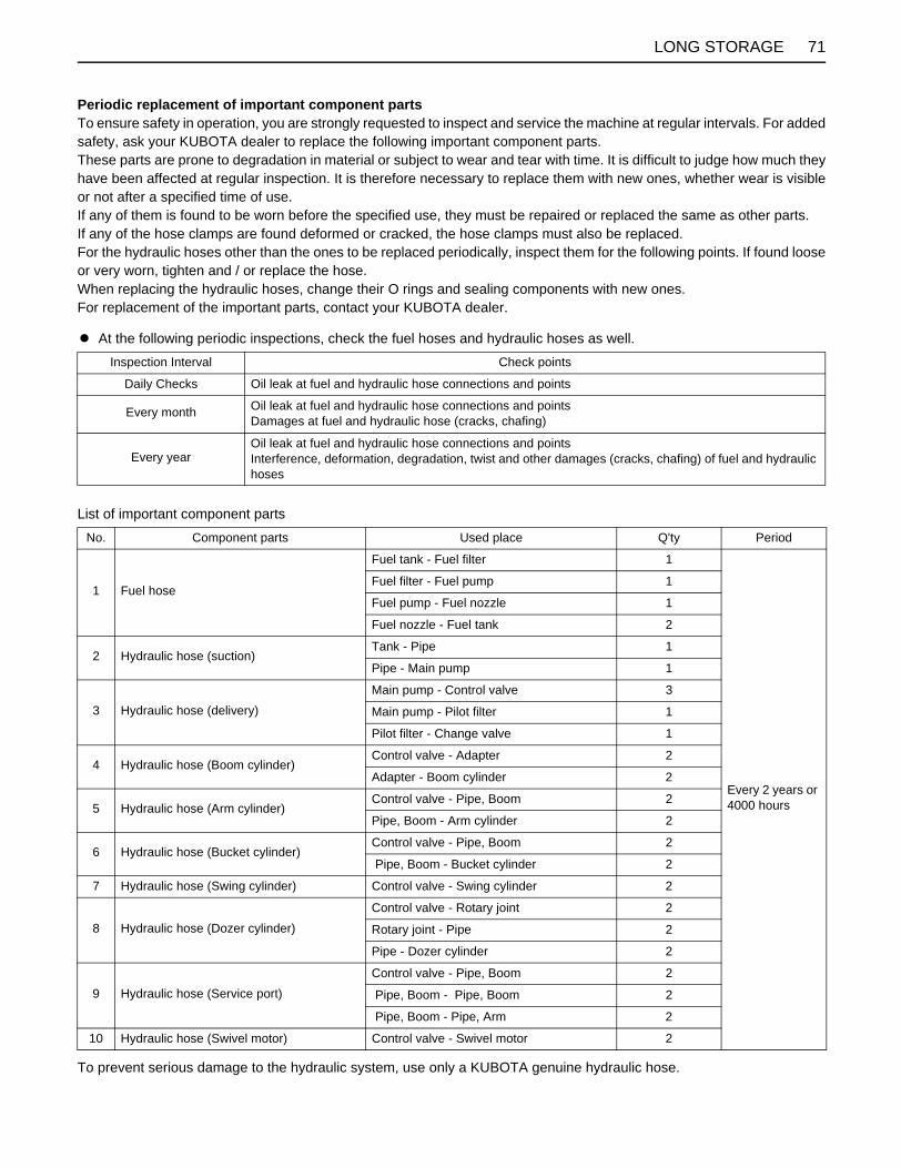
71LONG STORAGE
Periodic replacement of important component parts To ensure safety in operation, you are strongly requested to inspect and service the machine at regular intervals. For addedsafety, ask your KUBOTA dealer to replace the following important component parts. These parts are prone to degradation in material or subject to wear and tear with time. It is difficult to judge how much theyhave been affected at regular inspection. It is therefore necessary to replace them with new ones, whether wear is visibleor not after a specified time of use. If any of them is found to be worn before the specified use, they must be repaired or replaced the same as other parts. If any of the hose clamps are found deformed or cracked, the hose clamps must also be replaced. For the hydraulic hoses other than the ones to be replaced periodically, inspect them for the following points. If found looseor very worn, tighten and / or replace the hose. When replacing the hydraulic hoses, change their O rings and sealing components with new ones. For replacement of the important parts, contact your KUBOTA dealer.
A At the following periodic inspections, check the fuel hoses and hydraulic hoses as well.
List of important component parts
To prevent serious damage to the hydraulic system, use only a KUBOTA genuine hydraulic hose.
Inspection Interval Check points
Daily Checks Oil leak at fuel and hydraulic hose connections and points
Every month Oil leak at fuel and hydraulic hose connections and points Damages at fuel and hydraulic hose (cracks, chafing)
Every yearOil leak at fuel and hydraulic hose connections and points Interference, deformation, degradation, twist and other damages (cracks, chafing) of fuel and hydraulic hoses
No. Component parts Used place Q'ty Period
1 Fuel hose
Fuel tank - Fuel filter 1
Every 2 years or 4000 hours
Fuel filter - Fuel pump 1
Fuel pump - Fuel nozzle 1
Fuel nozzle - Fuel tank 2
2 Hydraulic hose (suction)Tank - Pipe 1
Pipe - Main pump 1
3 Hydraulic hose (delivery)Main pump - Control valve 3
Main pump - Pilot filter 1
Pilot filter - Change valve 1
4 Hydraulic hose (Boom cylinder)Control valve - Adapter 2
Adapter - Boom cylinder 2
5 Hydraulic hose (Arm cylinder)Control valve - Pipe, Boom 2
Pipe, Boom - Arm cylinder 2
6 Hydraulic hose (Bucket cylinder)Control valve - Pipe, Boom 2
Pipe, Boom - Bucket cylinder 2
7 Hydraulic hose (Swing cylinder) Control valve - Swing cylinder 2
8 Hydraulic hose (Dozer cylinder)Control valve - Rotary joint 2
Rotary joint - Pipe 2
Pipe - Dozer cylinder 2
9 Hydraulic hose (Service port)Control valve - Pipe, Boom 2
Pipe, Boom - Pipe, Boom 2
Pipe, Boom - Pipe, Arm 2
10 Hydraulic hose (Swivel motor) Control valve - Swivel motor 2
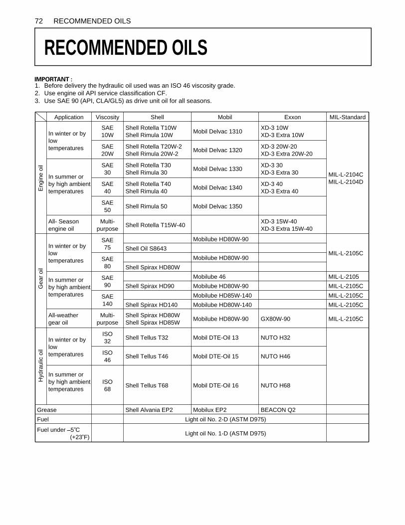
72 RECOMMENDED OILS
RECOMMENDED OILS
1. Before delivery the hydraulic oil used was an ISO 46 viscosity grade.2. Use engine oil API service classification CF.3. Use SAE 90 (API, CLA/GL5) as drive unit oil for all seasons.Application Viscosity Shell Mobil Exxon MIL-Standard
In winter or by low temperatures
SAE10W
Shell Rotella T10WShell Rimula 10W Mobil Delvac 1310 XD-3 10W
XD-3 Extra 10W
SAE20W
Shell Rotella T20W-2Shell Rimula 20W-2 Mobil Delvac 1320 XD-3 20W-20
XD-3 Extra 20W-20
In summer or by high ambient temperatures
SAE30
Shell Rotella T30Shell Rimula 30 Mobil Delvac 1330 XD-3 30
XD-3 Extra 30
SAE40
Shell Rotella T40Shell Rimula 40 Mobil Delvac 1340 XD-3 40
XD-3 Extra 40
SAE50 Shell Rimula 50 Mobil Delvac 1350
All- Season engine oil
Multi-purpose Shell Rotella T15W-40 XD-3 15W-40
XD-3 Extra 15W-40
In winter or by low temperatures
SAE75
Mobilube HD80W-90
MIL-L-2105CShell Oil S8643
SAE80
Mobilube HD80W-90Shell Spirax HD80W
In summer or by high ambient temperatures
SAE90
Mobilube 46 MIL-L-2105Shell Spirax HD90 Mobilube HD80W-90 MIL-L-2105C
SAE140
Mobilube HD85W-140 MIL-L-2105CShell Spirax HD140 Mobilube HD80W-140 MIL-L-2105C
All-weather gear oil
Multi-purpose
Shell Spirax HD80WShell Spirax HD85W Mobilube HD80W-90 GX80W-90 MIL-L-2105C
In winter or by low temperatures
ISO32 Shell Tellus T32 Mobil DTE-Oil 13 NUTO H32
ISO46 Shell Tellus T46 Mobil DTE-Oil 15 NUTO H46
In summer or by high ambient temperatures
ISO68 Shell Tellus T68 Mobil DTE-Oil 16 NUTO H68
Grease Shell Alvania EP2 Mobilux EP2 BEACON Q2Fuel Light oil No. 2-D (ASTM D975)
Fuel under 5 C(+23 F) Light oil No. 1-D (ASTM D975)
MIL-L-2104CMIL-L-2104D
Eng
ine
oil
Gea
r oil
Hyd
raul
ic o
il

73APPENDICES
APPENDICES
MAIN DIMENSIONS*until the end of the track.
With rubber track.
Dimensions in parentheses: CAB type models mm(A) (B) (C) (D) (E) (F) (G) (H) (I) (J)
KX91-3S2 410 475 1550 4940 3530 3185 2390 1310 3485 5245
U35-3S2 600 635 1700 4945 [4720]
3525 [3315]
3140 2230 850 3665 5260
(K) (L) (M) (N) (O) (P) (Q) (R) (S)
KX91-3S2 370 370 2440 1550 5135 1310 4795 1440 1900
U35-3S2 370 370 2440 1700 5145 1030* 4965 1440 2015 [2145]

74 LIFTING CAPACITY
LIFTING CAPACITY
1. The lifting capacities are based on ISO 10567 and do not exceed 75% of the static tilt load of the machine or 87% ofthe hydraulic lifting capacity of the machine.2. The strokes are as follows.
(1) The load point corresponds to the front bolt part of the arm.(2) The machine positions are (i) over - front (Blade down), (ii) over - front (Blade up), and (iii) over - side.(3) The operating cylinder is the boom cylinder.
3. The bucket of the excavator, the hook, the sling and other lifting accessories are taken into consideration for the loads.
Machine conditions:No bucket, all others according to the standard regulations.
To avoid personal injury or death:A No loads greater than those values mentioned in the lifting capacity tables are to be lifted.A The values mentioned in the table are valid only on even, hard grounds. When lifting on soft ground, the
machine can tip over due to the load being concentrated only on one side of the machine.A The table values are calculated at the end of the arm without the bucket. In order to find the allowable loads
for machines with bucket, the bucket weight must be subtracted from the values in the table.

75LIFTING CAPACITY

76 LIFTING CAPACITY

77LIFTING CAPACITY

78 LIFTING CAPACITY