models for transmission lines. transmission capacity hvdc ... · models for transmission lines....
TRANSCRIPT
10/19/2006
Fyrirlestur nr 15/EBH 1Greining raforkukerfa - 08.31.41
Models for Transmission Lines.Transmission Capacity HVDC Transmission
10/19/2006
Fyrirlestur nr 15/EBH 2Greining raforkukerfa - 08.31.41
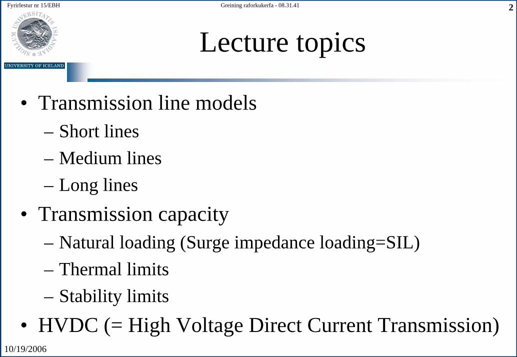
Lecture topics
• Transmission line models– Short lines– Medium lines– Long lines
• Transmission capacity– Natural loading (Surge impedance loading=SIL)– Thermal limits– Stability limits
• HVDC (= High Voltage Direct Current Transmission)
10/19/2006
Fyrirlestur nr 15/EBH 3Greining raforkukerfa - 08.31.41
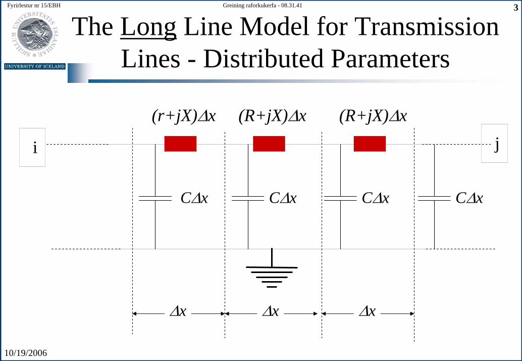
The Long Line Model for Transmission Lines - Distributed Parameters
(R+jX)∆x
i j
∆x
(r+jX)∆x (R+jX)∆x
∆x ∆x
C∆x C∆x C∆xC∆x

10/19/2006
Fyrirlestur nr 15/EBH 4Greining raforkukerfa - 08.31.41
The Long Line Model for Transmission Lines - Distributed Parameters
z∆x1 2
∆x
y∆x
V V V z x I+∆ = + ∆ ⋅
10
z R jX
y G jB jCω
= +
= + = − V V+ ∆ V
I I+ ∆ I
I∆
V z x I∆ = ∆ ⋅
dV z Idx
= ⋅
I I I y x V+ ∆ = + ∆ ⋅
I y x V∆ = ∆ ⋅
dI y Vdx
= ⋅
•Voltage and Current conditions lead to:
•Impedance and addmitance per unitlength of line:
x
10/19/2006
Fyrirlestur nr 15/EBH 5Greining raforkukerfa - 08.31.41
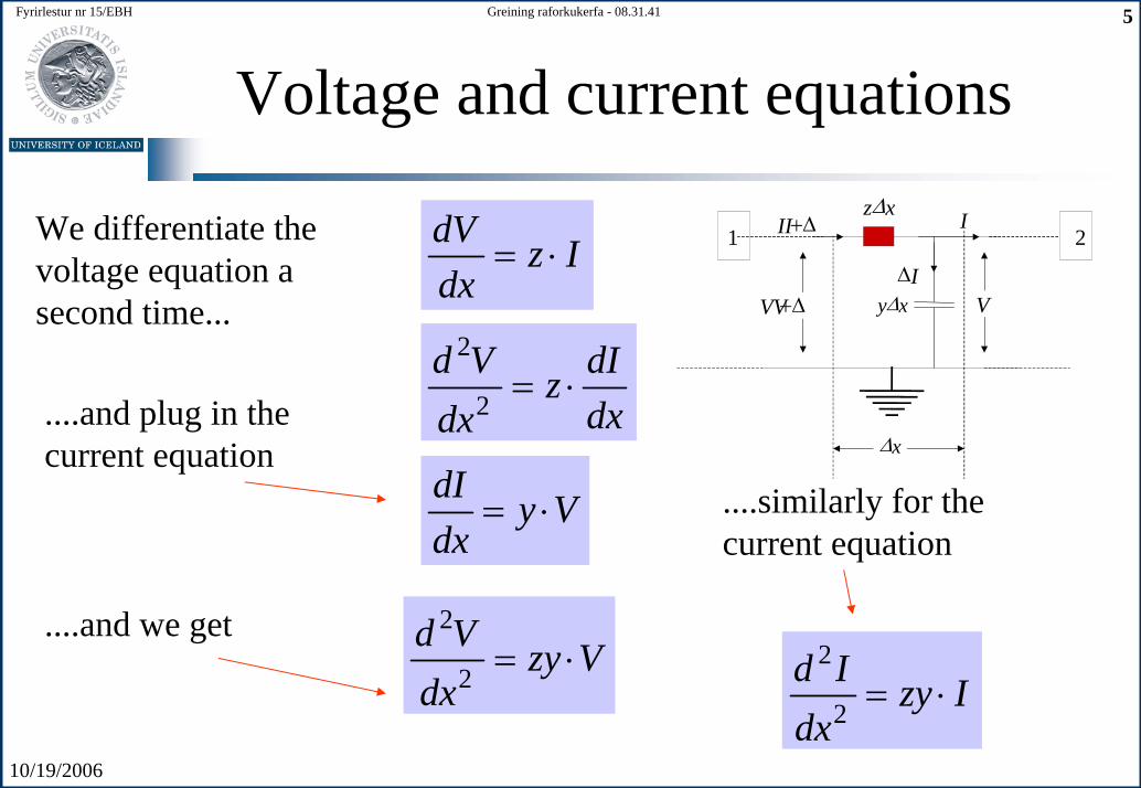
Voltage and current equationsz∆x
1 2
∆x
y∆xVV+∆ V
II+∆ I
I∆
dV z Idx
= ⋅We differentiate thevoltage equation a second time...
2
2d V dIz
dxdx= ⋅
....and plug in thecurrent equation
dI y Vdx
= ⋅ ....similarly for thecurrent equation
2
2d V zy Vdx
= ⋅....and we get
2
2d I zy Idx
= ⋅
10/19/2006
Fyrirlestur nr 15/EBH 6Greining raforkukerfa - 08.31.41
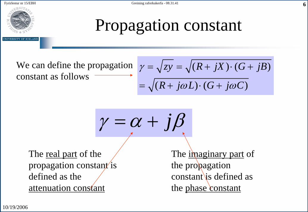
Propagation constant
( ) ( )
( ) ( )
zy R jX G jB
R j L G j C
γ
ω ω
= = + ⋅ +
= + ⋅ +
We can define the propagationconstant as follows
The real part of thepropagation constant isdefined as theattenuation constant
jγ α β= +The imaginary part of the propagationconstant is defined as the phase constant
10/19/2006
Fyrirlestur nr 15/EBH 7Greining raforkukerfa - 08.31.41
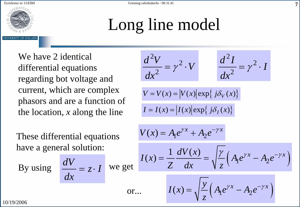
Long line model
We have 2 identicaldifferential equationsregarding bot voltage and current, which are complexphasors and are a function of the location, x along the line
22
2d V Vdx
γ= ⋅2
22
d I Idx
γ= ⋅
{ }( ) ( ) exp ( )VV V x V x j xδ= =
{ }( ) ( ) exp ( )II I x I x j xδ= =
1 2( ) x xV x A e A eγ γ−= +These differential equationshave a general solution:
( )1 21 ( )( ) x xdV xI x A e A eZ dx z
γ γγ −= = −dV z Idx
= ⋅ we getBy using
( )1 2( ) x xyI x A e A ez
γ γ−= −or...
10/19/2006
Fyrirlestur nr 15/EBH 8Greining raforkukerfa - 08.31.41
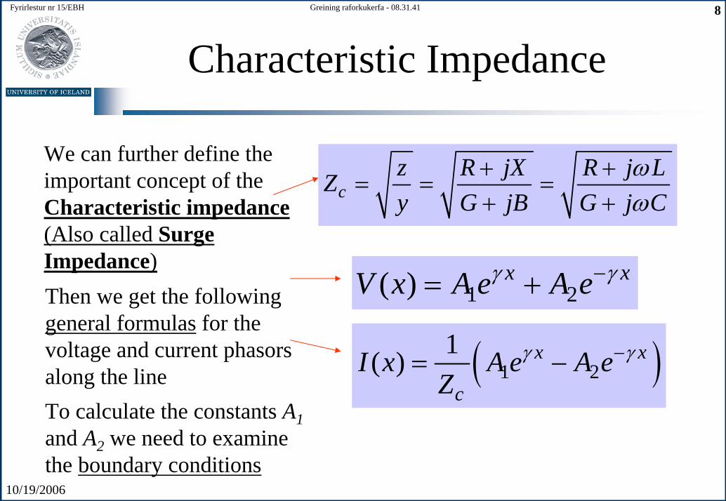
Characteristic Impedance
We can further define theimportant concept of theCharacteristic impedance(Also called SurgeImpedance)
cz R jX R j LZy G jB G j C
ωω
+ += = =
+ +
Then we get the followinggeneral formulas for thevoltage and current phasorsalong the line
1 2( ) x xV x A e A eγ γ−= +
( )1 21( ) x x
cI x A e A e
Zγ γ−= −
To calculate the constants A1and A2 we need to examinethe boundary conditions
10/19/2006
Fyrirlestur nr 15/EBH 9Greining raforkukerfa - 08.31.41
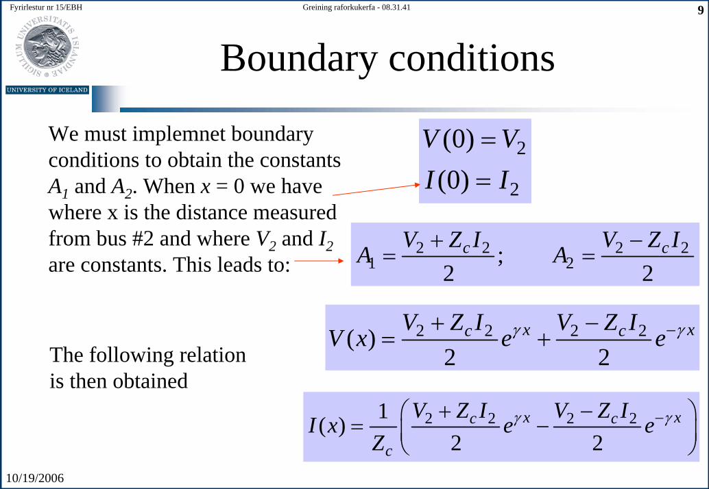
Boundary conditions
We must implemnet boundaryconditions to obtain the constantsA1 and A2. When x = 0 we havewhere x is the distance measuredfrom bus #2 and where V2 and I2are constants. This leads to:
2
2
(0)(0)
V VI I
==
2 2 2 21 2;
2 2c cV Z I V Z I
A A+ −
= =
2 2 2 2( )2 2
x xc cV Z I V Z IV x e eγ γ−+ −
= +The following relationis then obtained
2 2 2 21( )2 2
x xc c
c
V Z I V Z II x e e
Zγ γ−+ −⎛ ⎞= −⎜ ⎟
⎝ ⎠

10/19/2006
Fyrirlestur nr 15/EBH 10Greining raforkukerfa - 08.31.41
Model for long lines
2 2( ) cosh sinhcV x V x I Z xγ γ= +Next we get the followingrelations for voltage and current along the line
2 21( ) sinh coshc
I x V x I xZ
γ γ= +
1 2 2cosh sinhcV V I Zγ γ= +At bus #1 we get the followingrelation:
1 2 21 sinh coshc
I V IZ
γ γ= +is the line length
10/19/2006
Fyrirlestur nr 15/EBH 11Greining raforkukerfa - 08.31.41
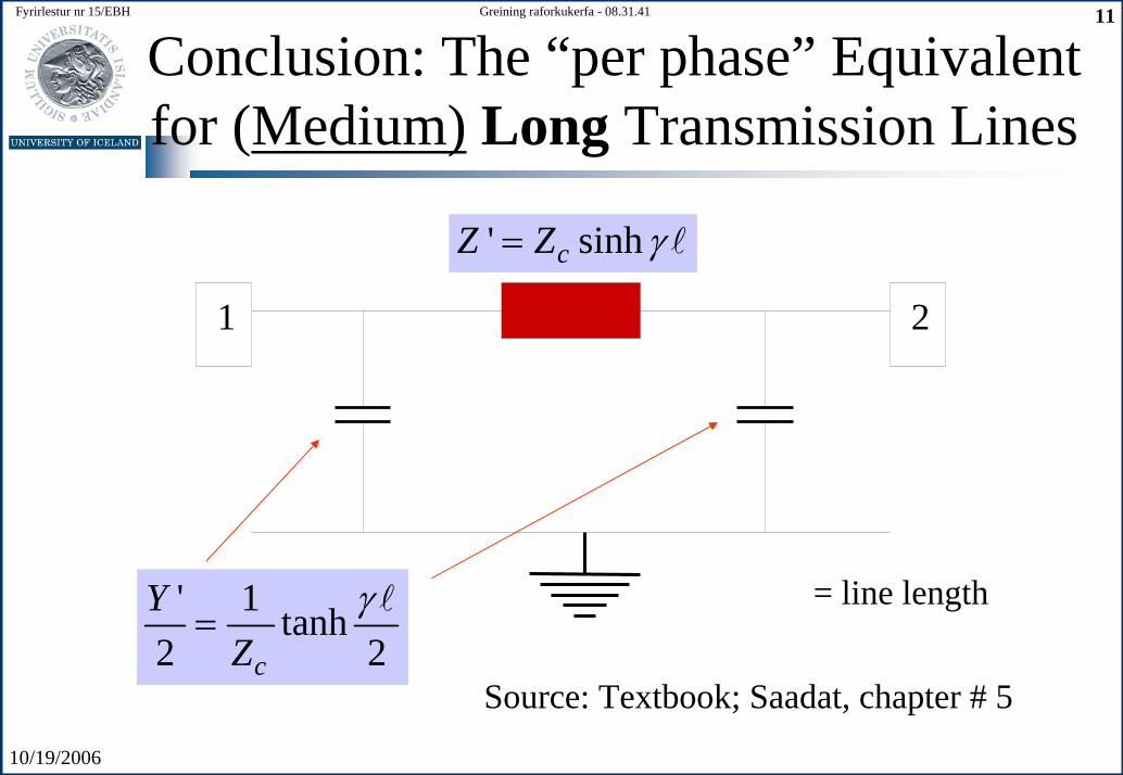
Conclusion: The “per phase” Equivalent for (Medium) Long Transmission Lines
' sinhcZ Z γ=
1 2
' 1 tanh2 2c
YZ
γ=
= line length
Source: Textbook; Saadat, chapter # 5

10/19/2006
Fyrirlestur nr 15/EBH 12Greining raforkukerfa - 08.31.41
The “per phase” Circuit Equivalent for Short Transmission Lines
R+jX1 2
Bus #1 Bus #2
Load impedance
10/19/2006
Fyrirlestur nr 15/EBH 13Greining raforkukerfa - 08.31.41
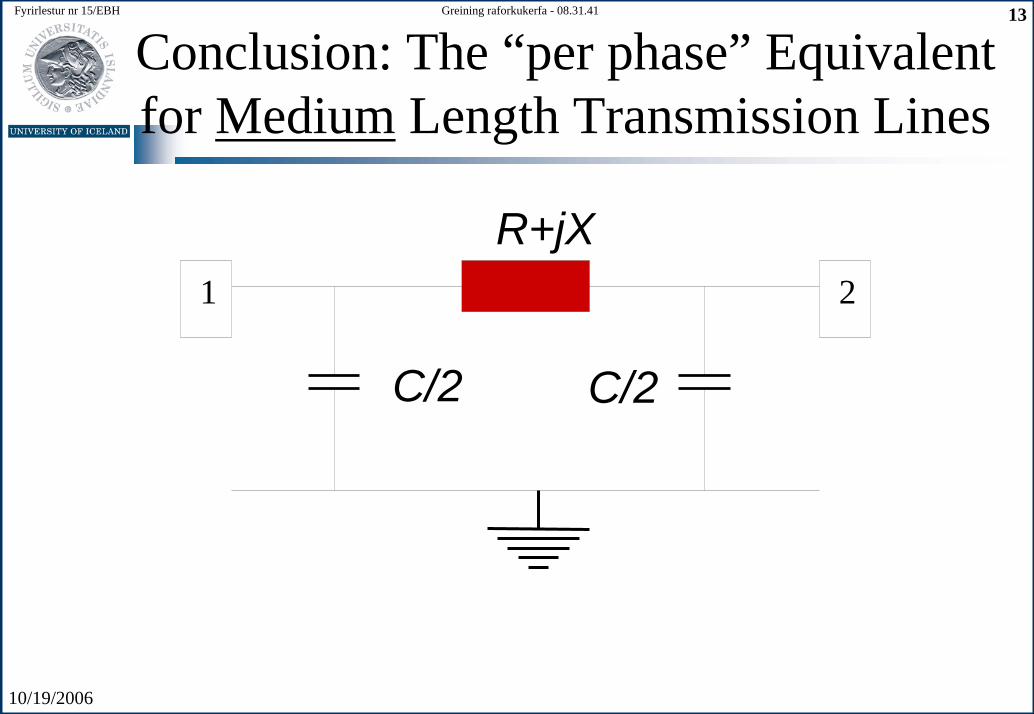
Conclusion: The “per phase” Equivalent for Medium Length Transmission Lines
C/2
R+jX1 2
C/2
10/19/2006
Fyrirlestur nr 15/EBH 14Greining raforkukerfa - 08.31.41
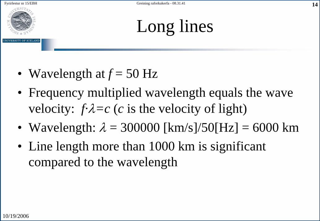
Long lines
• Wavelength at f = 50 Hz• Frequency multiplied wavelength equals the wave
velocity: f·λ=c (c is the velocity of light)• Wavelength: λ = 300000 [km/s]/50[Hz] = 6000 km• Line length more than 1000 km is significant
compared to the wavelength
10/19/2006
Fyrirlestur nr 15/EBH 15Greining raforkukerfa - 08.31.41
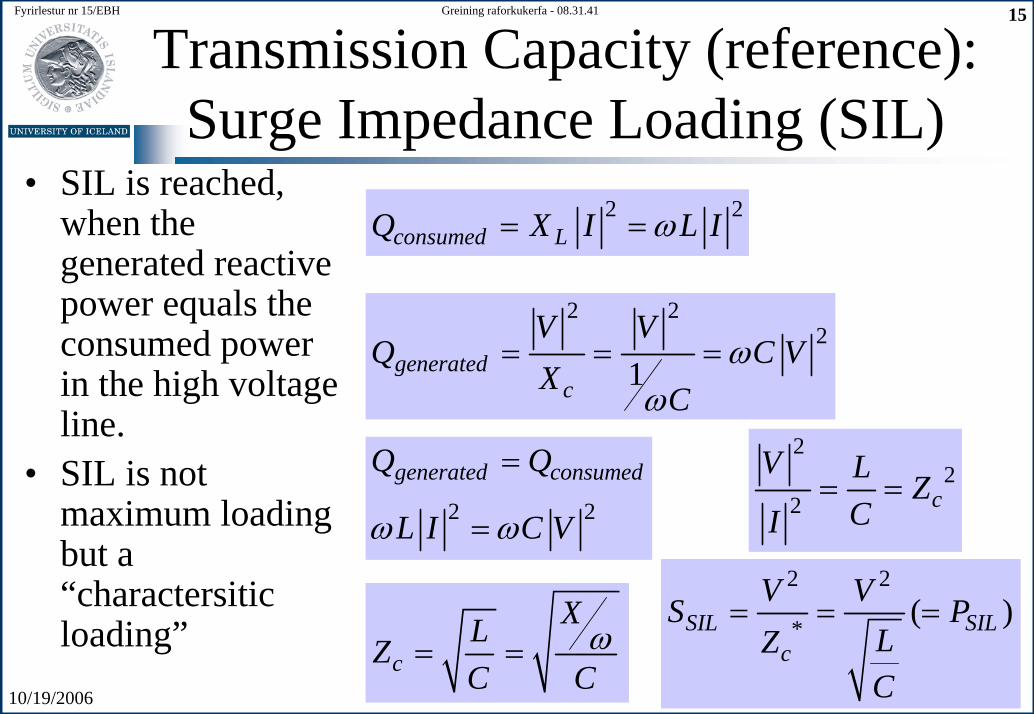
Transmission Capacity (reference): Surge Impedance Loading (SIL)
• SIL is reached, when thegenerated reactivepower equals theconsumed powerin the high voltageline.
• SIL is not maximum loadingbut a “charactersiticloading”
2 2consumed LQ X I L Iω= =
2 22
1generatedc
V VQ C V
X Cω
ω= = =
2 2
generated consumedQ Q
L I C Vω ω
=
=
c
XLZC C
ω= =
22
2 cV L Z
CI= =
2 2
* ( )SIL SILc
V VS PLZC
= = =
10/19/2006
Fyrirlestur nr 15/EBH 16Greining raforkukerfa - 08.31.41
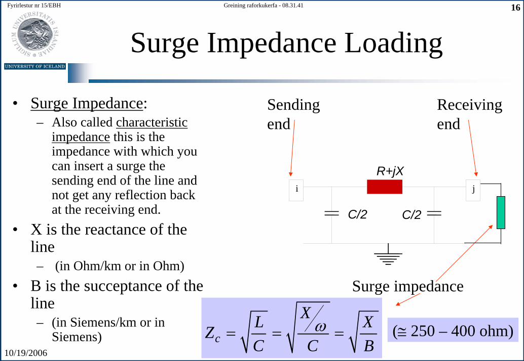
Surge Impedance Loading
• Surge Impedance: – Also called characteristic
impedance this is theimpedance with which youcan insert a surge thesending end of the line and not get any reflection backat the receiving end.
• X is the reactance of theline– (in Ohm/km or in Ohm)
• B is the succeptance of theline– (in Siemens/km or in
Siemens)
Surge impedance
Receivingend
Sending end
c
XL XZC C B
ω= = = (≅ 250 – 400 ohm)
C/2
R+jXi j
C/2
10/19/2006
Fyrirlestur nr 15/EBH 17Greining raforkukerfa - 08.31.41
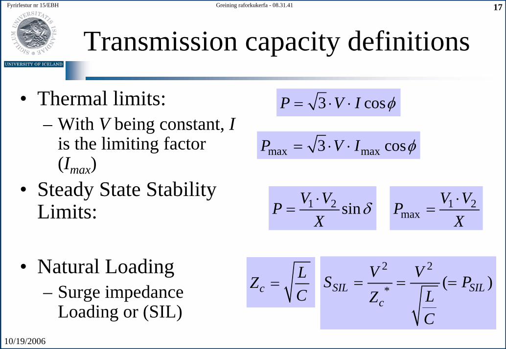
Transmission capacity definitions
• Thermal limits:– With V being constant, I
is the limiting factor(Imax)
• Steady State StabilityLimits:
• Natural Loading– Surge impedance
Loading or (SIL)
3 cosP V I φ= ⋅ ⋅
max max3 cosP V I φ= ⋅ ⋅
1 2 sinV VPX
δ⋅
= 1 2max
V VPX⋅
=
2 2
* ( )SIL SILc
V VS PLZC
= = =cLZC
=
10/19/2006
Fyrirlestur nr 15/EBH 18Greining raforkukerfa - 08.31.41
HVDC Transmission
High Voltage Direct CurrentTransmission
Orkuflutningar með jafnstraumstækni
10/19/2006
Fyrirlestur nr 15/EBH 19Greining raforkukerfa - 08.31.41
HVDC Transmission
• Point to point (from “A” to “B”) rather than meshednetwork. No commercially available DC circuitbreakers
• Used exclusively for long underground/submarinecable transmission
• Flexible Computer or Electronic control of power flow• Transmission over long distances by HVDC overhead
line• Recently “HVDC light”. Lower cost of AC/DC
converters
10/19/2006
Fyrirlestur nr 15/EBH 20Greining raforkukerfa - 08.31.41
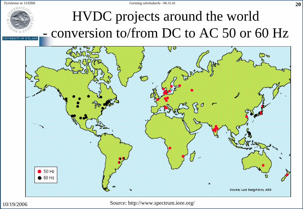
HVDC projects around the world- conversion to/from DC to AC 50 or 60 Hz
Source: http://www.spectrum.ieee.org/
10/19/2006
Fyrirlestur nr 15/EBH 21Greining raforkukerfa - 08.31.41
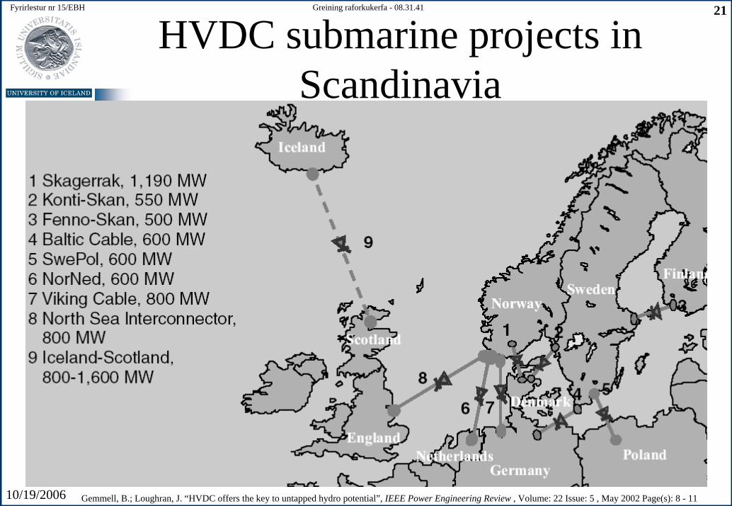
HVDC submarine projects in Scandinavia
Gemmell, B.; Loughran, J. “HVDC offers the key to untapped hydro potential”, IEEE Power Engineering Review , Volume: 22 Issue: 5 , May 2002 Page(s): 8 - 11
10/19/2006
Fyrirlestur nr 15/EBH 22Greining raforkukerfa - 08.31.41
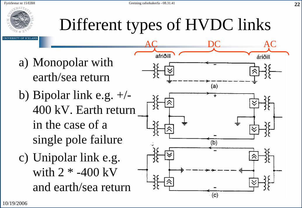
Different types of HVDC links
a) Monopolar withearth/sea return
b) Bipolar link e.g. +/-400 kV. Earth return in the case of a single pole failure
c) Unipolar link e.g. with 2 * -400 kVand earth/sea return
DCAC AC
10/19/2006
Fyrirlestur nr 15/EBH 23Greining raforkukerfa - 08.31.41
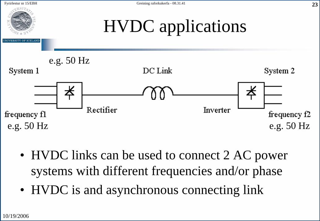
HVDC applications
e.g. 50 Hz
e.g. 50 Hze.g. 50 Hz
• HVDC links can be used to connect 2 AC powersystems with different frequencies and/or phase
• HVDC is and asynchronous connecting link
10/19/2006
Fyrirlestur nr 15/EBH 24Greining raforkukerfa - 08.31.41
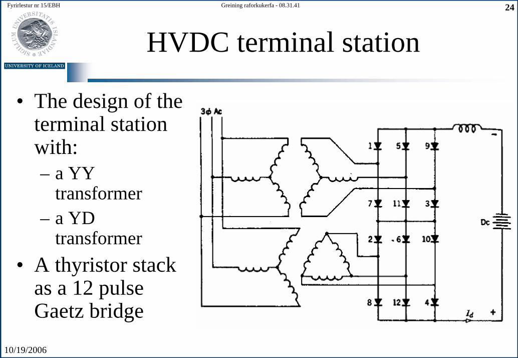
HVDC terminal station
• The design of theterminal stationwith:– a YY
transformer– a YD
transformer• A thyristor stack
as a 12 pulseGaetz bridge
10/19/2006
Fyrirlestur nr 15/EBH 25Greining raforkukerfa - 08.31.41
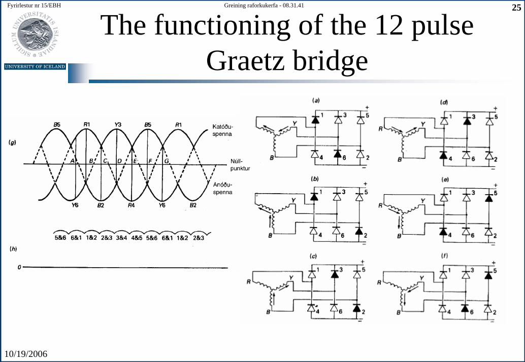
The functioning of the 12 pulseGraetz bridge
10/19/2006
Fyrirlestur nr 15/EBH 26Greining raforkukerfa - 08.31.41
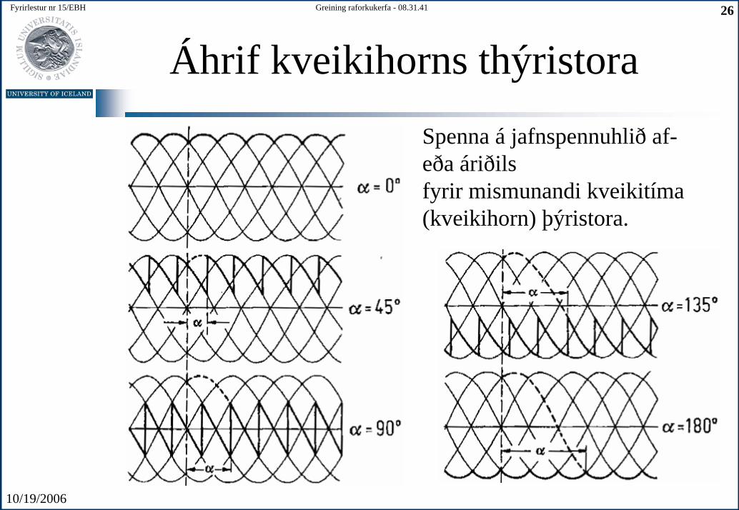
Áhrif kveikihorns thýristora
Spenna á jafnspennuhlið af-eða áriðils fyrir mismunandi kveikitíma (kveikihorn) þýristora.
10/19/2006
Fyrirlestur nr 15/EBH 27Greining raforkukerfa - 08.31.41
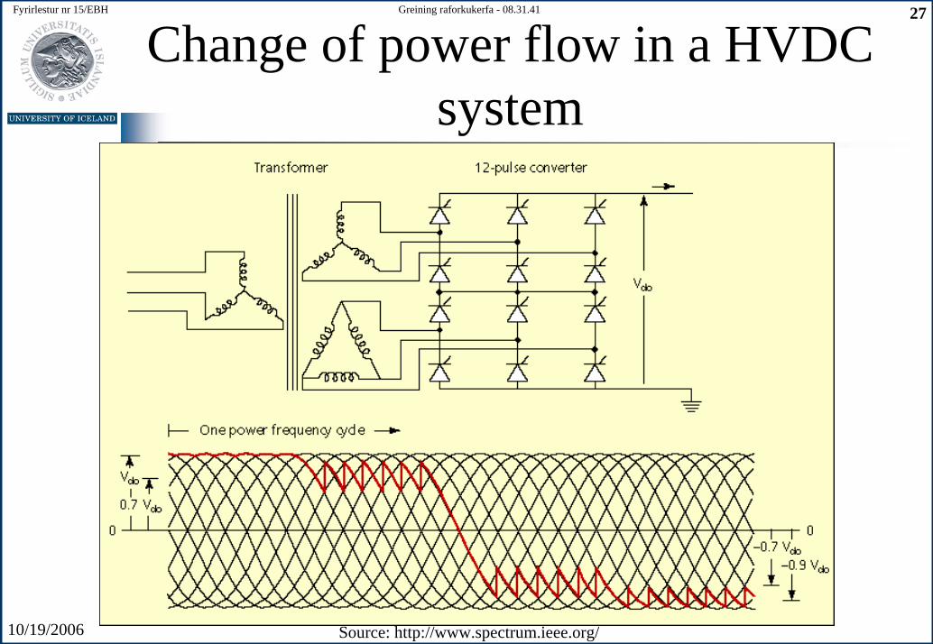
Change of power flow in a HVDC system
Source: http://www.spectrum.ieee.org/
10/19/2006
Fyrirlestur nr 15/EBH 28Greining raforkukerfa - 08.31.41
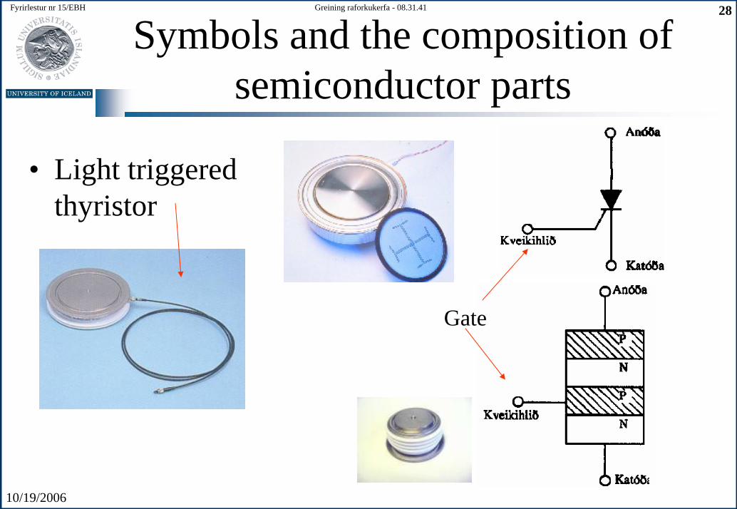
Symbols and the composition of semiconductor parts
• Light triggeredthyristor
Gate
10/19/2006
Fyrirlestur nr 15/EBH 29Greining raforkukerfa - 08.31.41
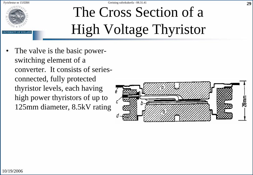
The Cross Section of a High Voltage Thyristor
• The valve is the basic power-switching element of a converter. It consists of series-connected, fully protectedthyristor levels, each havinghigh power thyristors of up to125mm diameter, 8.5kV rating
10/19/2006
Fyrirlestur nr 15/EBH 30Greining raforkukerfa - 08.31.41
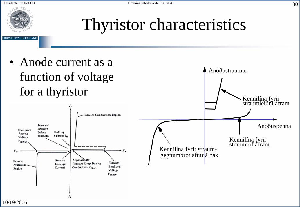
Thyristor characteristics
• Anode current as a function of voltagefor a thyristor
Anóðustraumur
Anóðuspenna
Kennilína fyrir straumrof áfram
gegnumbrot aftur á bak
Kennilína fyrir straumleiðni áfram
Kennilína fyrir straum-
10/19/2006
Fyrirlestur nr 15/EBH 31Greining raforkukerfa - 08.31.41
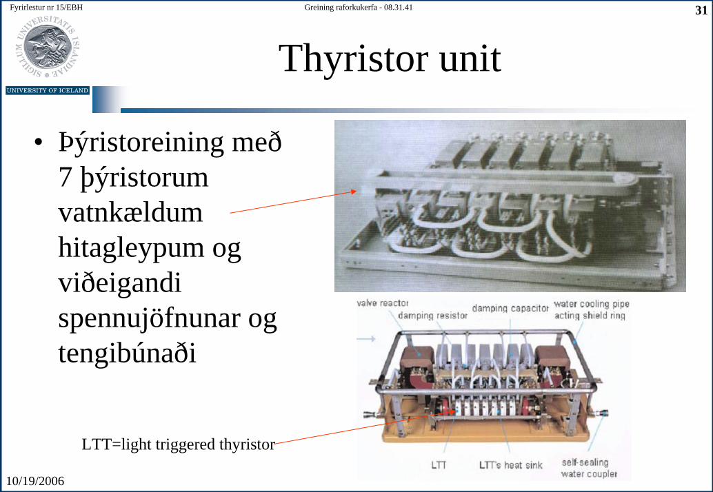
Thyristor unit
• Þýristoreining með 7 þýristorumvatnkældum hitagleypum og viðeigandi spennujöfnunar og tengibúnaði
LTT=light triggered thyristor
10/19/2006
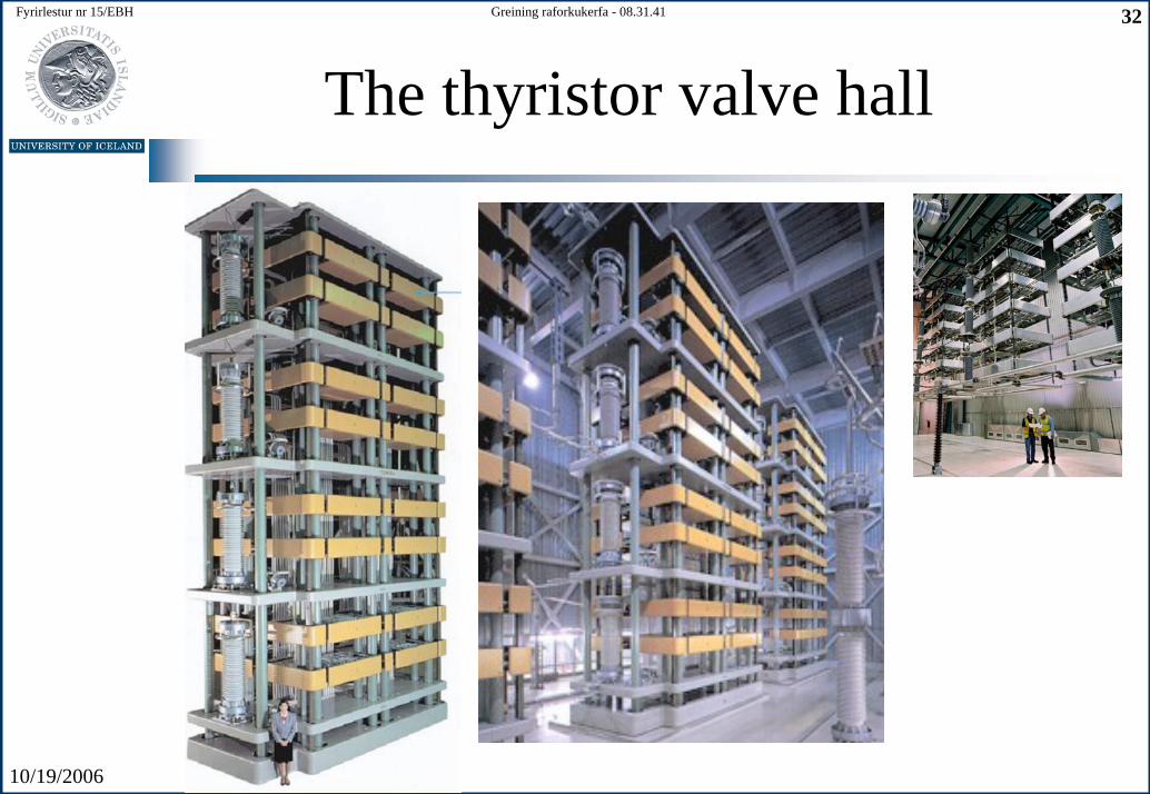
Fyrirlestur nr 15/EBH 32Greining raforkukerfa - 08.31.41
The thyristor valve hall
10/19/2006
Fyrirlestur nr 15/EBH 33Greining raforkukerfa - 08.31.41
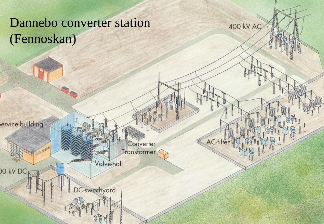
Dannebo converter station(Fennoskan)
10/19/2006
Fyrirlestur nr 15/EBH 34Greining raforkukerfa - 08.31.41
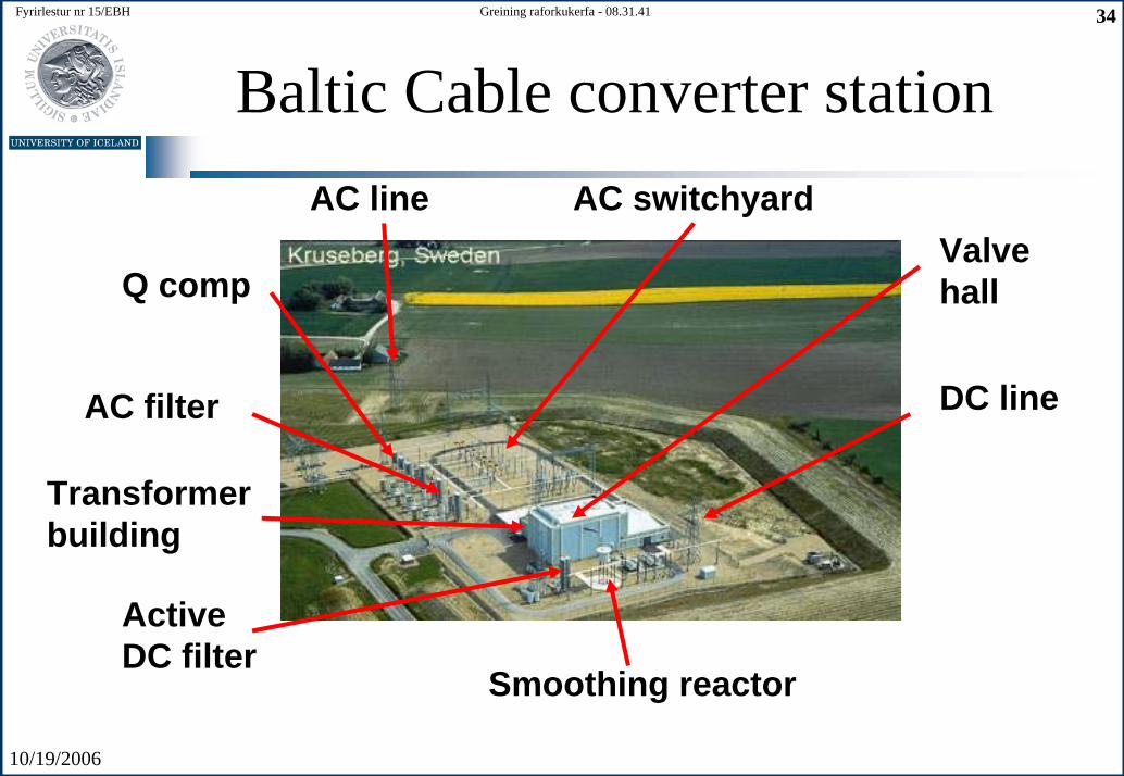
Baltic Cable converter stationAC line AC switchyard
Q compValvehall
DC lineAC filter
ActiveDC filter
Transformer building
Smoothing reactor
10/19/2006
Fyrirlestur nr 15/EBH 35Greining raforkukerfa - 08.31.41
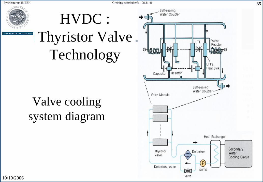
HVDC : Thyristor Valve
Technology
Valve coolingsystem diagram

10/19/2006
Fyrirlestur nr 15/EBH 36Greining raforkukerfa - 08.31.41
The evolution of a thyristor’s currentand voltage capacity 1970-1995
0
1
2
3
4
5
6
1970 1975 1980 1985 1990
Málgildi jafnstraumsí gegnum þýristor
Hæsta lokunarspennaþýristors
Straumur (kA)
2
4
6
8Spenna (kV)
10/19/2006
Fyrirlestur nr 15/EBH 37Greining raforkukerfa - 08.31.41
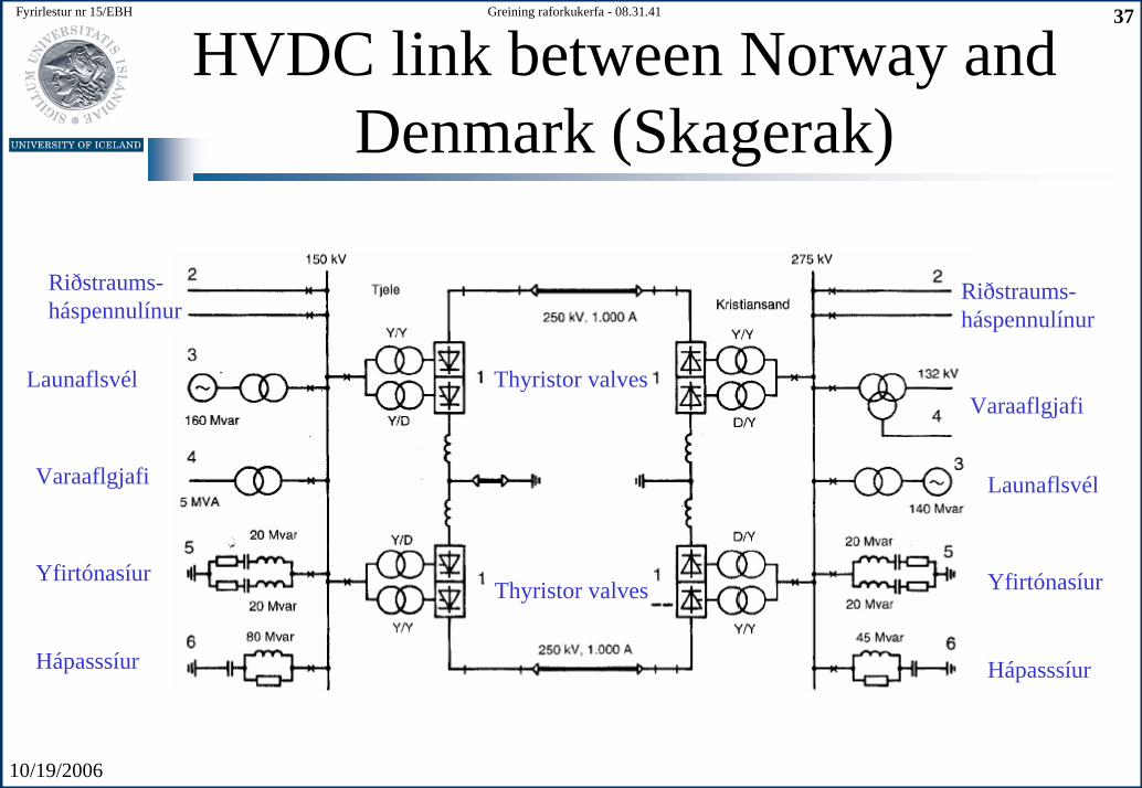
HVDC link between Norway and Denmark (Skagerak)
Riðstraums-háspennulínur
Launaflsvél
Varaaflgjafi
Yfirtónasíur
Hápasssíur
Thyristor valves
Thyristor valves
Varaaflgjafi
Riðstraums-háspennulínur
Launaflsvél
Yfirtónasíur
Hápasssíur
10/19/2006
Fyrirlestur nr 15/EBH 38Greining raforkukerfa - 08.31.41
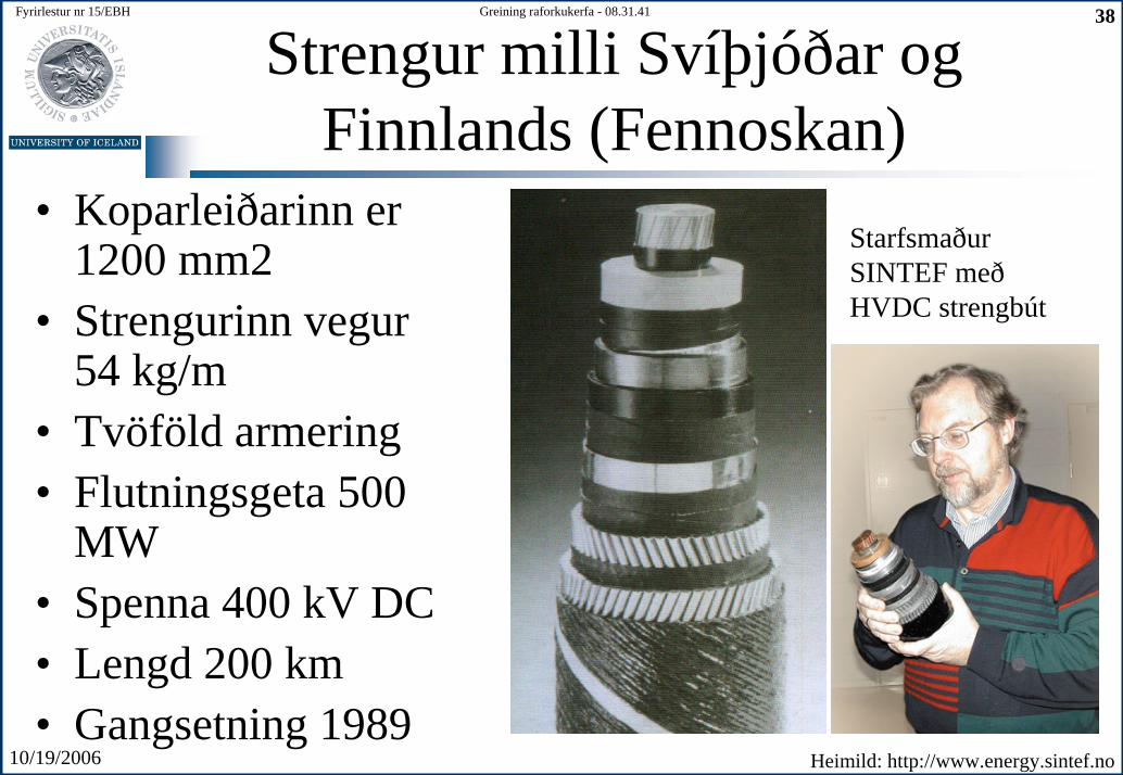
Strengur milli Svíþjóðar og Finnlands (Fennoskan)
• Koparleiðarinn er 1200 mm2
• Strengurinn vegur 54 kg/m
• Tvöföld armering• Flutningsgeta 500
MW• Spenna 400 kV DC• Lengd 200 km• Gangsetning 1989
Starfsmaður SINTEF með HVDC strengbút
Heimild: http://www.energy.sintef.no
10/19/2006
Fyrirlestur nr 15/EBH 39Greining raforkukerfa - 08.31.41
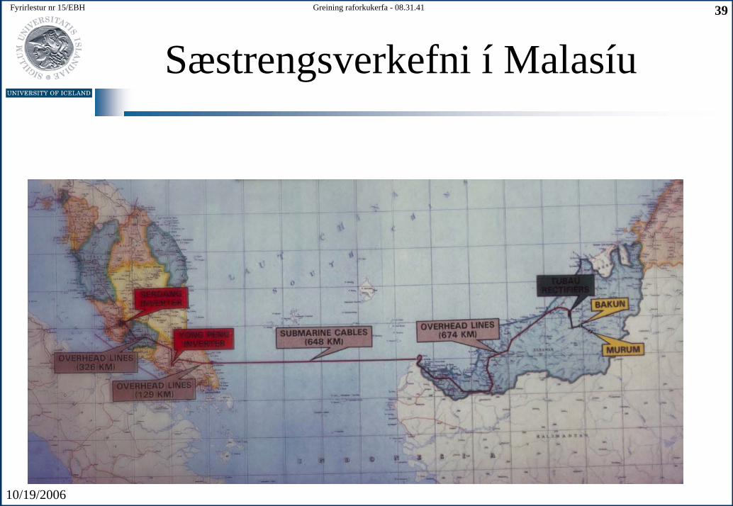
Sæstrengsverkefni í Malasíu
10/19/2006
Fyrirlestur nr 15/EBH 40Greining raforkukerfa - 08.31.41
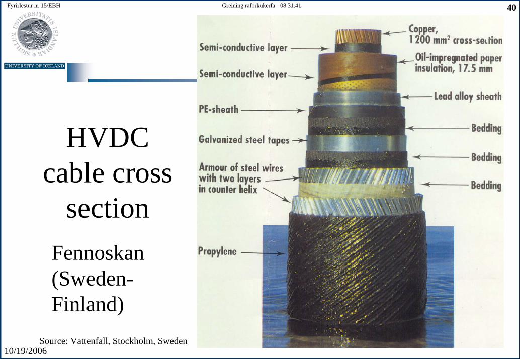
HVDC cable cross
sectionFennoskan(Sweden-Finland)
Source: Vattenfall, Stockholm, Sweden
10/19/2006
Fyrirlestur nr 15/EBH 41Greining raforkukerfa - 08.31.41
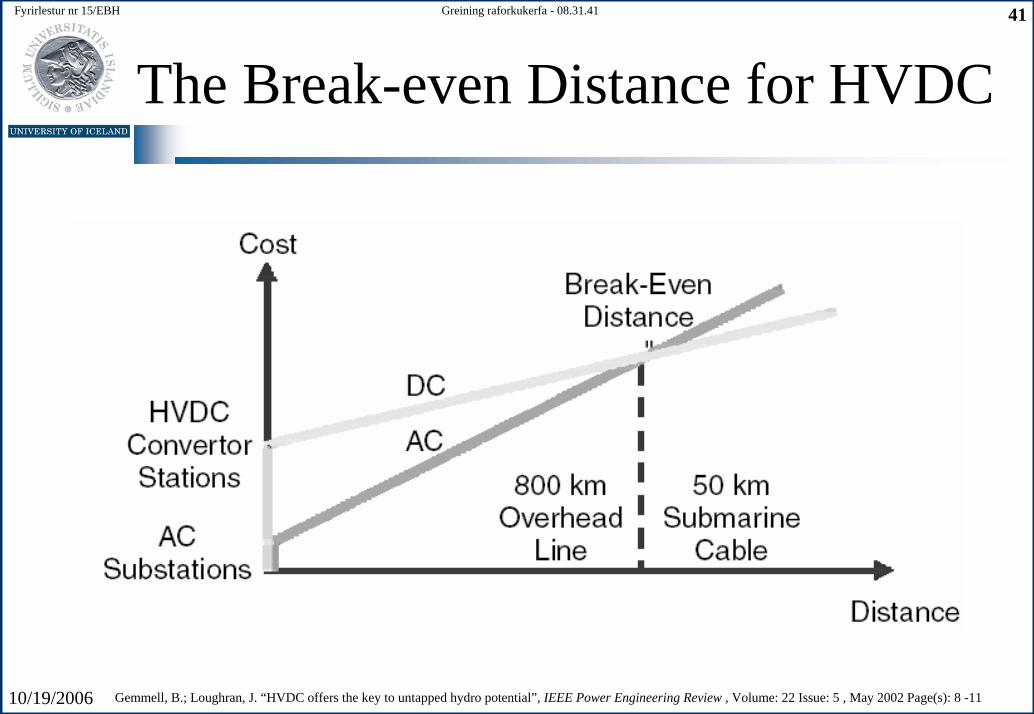
The Break-even Distance for HVDC
Gemmell, B.; Loughran, J. “HVDC offers the key to untapped hydro potential”, IEEE Power Engineering Review , Volume: 22 Issue: 5 , May 2002 Page(s): 8 -11
10/19/2006
Fyrirlestur nr 15/EBH 42Greining raforkukerfa - 08.31.41
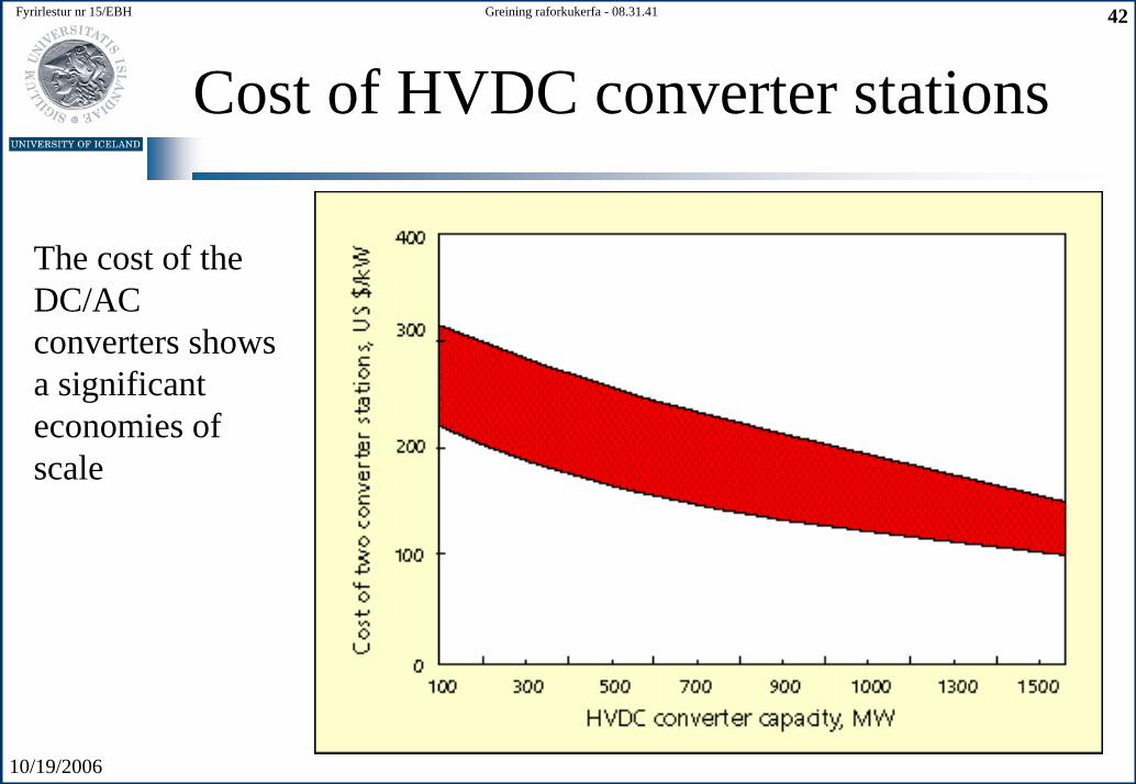
Cost of HVDC converter stations
The cost of theDC/AC converters showsa significanteconomies of scale
10/19/2006
Fyrirlestur nr 15/EBH 43Greining raforkukerfa - 08.31.41
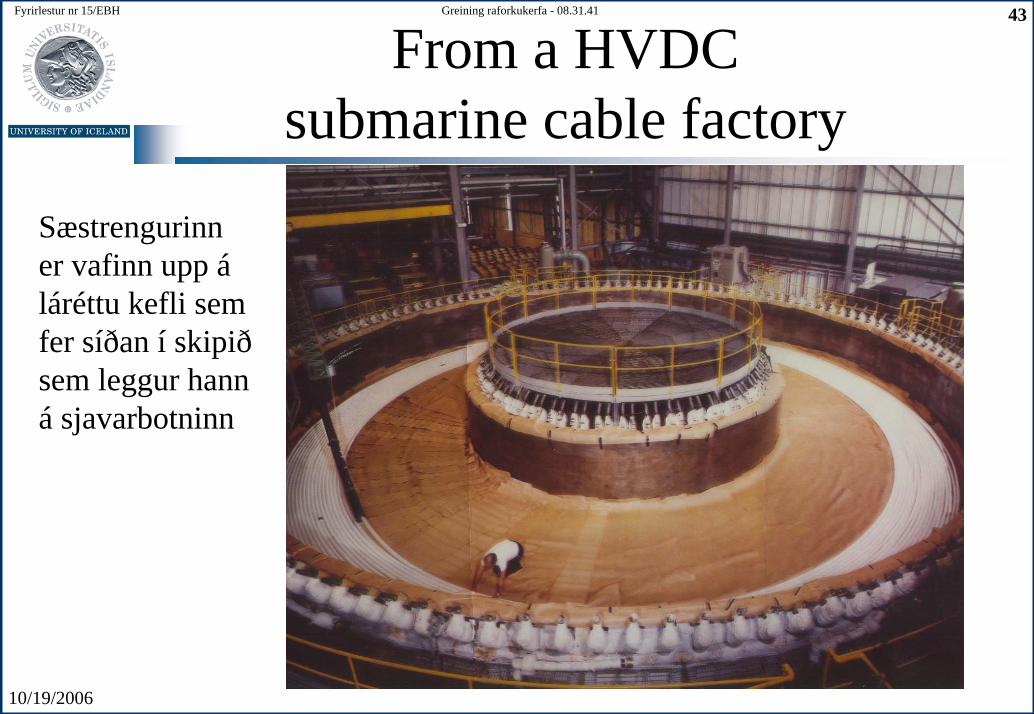
From a HVDC submarine cable factory
Sæstrengurinn er vafinn upp áláréttu kefli sem fer síðan í skipið sem leggur hann á sjavarbotninn
10/19/2006
Fyrirlestur nr 15/EBH 44Greining raforkukerfa - 08.31.41
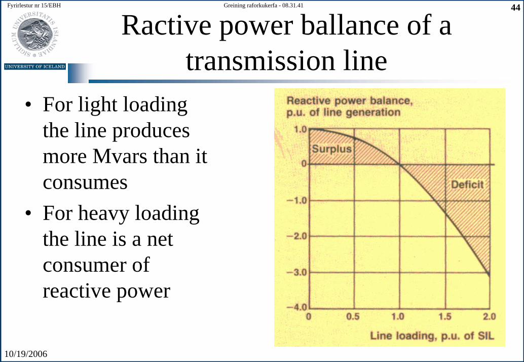
Ractive power ballance of a transmission line
• For light loadingthe line producesmore Mvars than it consumes
• For heavy loadingthe line is a net consumer of reactive power
10/19/2006
Fyrirlestur nr 15/EBH 45Greining raforkukerfa - 08.31.41
References
• Gemmell, B.; Loughran, J. “HVDC offers the key to untapped hydropotential”, IEEE Power Engineering Review , Volume: 22 Issue: 5 , May 2002 Page(s): 8 –11
• The rise of high-voltage, direct-current systems by Narain G. Hingorani, Consultant (1996) http://www.spectrum.ieee.org/