(models g203, g203s, and g213) operation manual · design g 203 g 203s g 213 diffusion inlet visual...
TRANSCRIPT

Micro III (Models G203, G203S, and G213)
Operation Manual
Worldwide Manufacturer of Gas Detection Solutions


Table of contents Page
Introduction ........................................................................................ 3 For your safety .................................................................................... 3 Application and use ............................................................................ 3 General description ............................................................................ 4 Detection principle............................................................................. 4 Design................................................................................................... 5
Operational notes................................................................................... 5 Detection mode .................................................................................. 5
Turning on ........................................................................................ 6 Display illumination ......................................................................... 7 Peak and minimum value memory ............................................... 7 Turning off ....................................................................................... 7 Alarm................................................................................................. 8 Alarm signals .................................................................................... 8 Special notes for oxygen monitoring ........................................... 9 Battery .............................................................................................. 9 Check of battery capacity............................................................. 11
Service mode..................................................................................... 11 Activation ....................................................................................... 11 Confidence beep ........................................................................... 13 Sensor adjustment with fresh air ................................................ 14 Sensor adjustment with test gas ................................................. 15 Sensor replacement ...................................................................... 17 Adjustment by means of configuration program..................... 17
Annex..................................................................................................... 17 Cleaning.............................................................................................. 17 Service and repair ............................................................................. 18 Maintenance and inspection ........................................................... 18 Accessories......................................................................................... 19 Spare parts......................................................................................... 19 Types of sensors and detection range........................................... 21 Sensor specification.......................................................................... 22 Alarm thresholds-standard settings and test gas chart............... 26 Technical data.................................................................................... 28

Introduction For your safety According to § 3 of the law about technical working media, this manual points out the proper use of the product and serves to prevent dangers. This manual must be carefully read by all individuals who have or will have the responsibility for using and servicing this product. As any piece of complex equipment, the GfG MICRO III will do the job designed to do, only, if it is used and serviced in accordance with the manufacturer's instructions. If the product is not used and serviced in accordance with the instructions in this manual the warranty will be voided. Adjustments in the service mode must be done by experts only. Before operating the detector, use the operational beep to check the battery status, the alarm signal activation, and the readiness for operation. The above does not alter statements regarding GfG's warranties and conditions of sale and delivery. Application and use The MICRO III is meant for personal safety under atmospheric conditions. It is a pocketsize detector for your personal protection from gas hazards. The detector is operating continuously in diffusion mode and gives a visual and audible alarm, if dangerous gas concentrations build up. The Micro III is approved for the use in explosion-endangered areas and is subject to an EC-type examination certificate issued by DMT Deutsche Montan Technologie GmbH, according to regulation 94/9/EG (ATEX100a): Certificate: DMT 99 ATEX E 044 Labeling: ⎯ II 2G EEx ib IIC T6 resp. T5 -20°C ≤ Ta ≤ +40°C resp.+50°.
3

General description The MICRO III is a very small and handy single gas monitor for measuring toxic gases or oxygen deficiency resp. surplus. There are 7 models of the MICRO III available: MICRO III model
Display Keypad Memory Gases and lines
G 201 No No No O CO H2 2S (*1)
G 202 Yes No No O CO H2 2S H2 NO NH3 HCN HCl SO (*1)2
G 202s Yes No No O CO H2 2S H2 C2H4O SiH4 PH3 COCl2 THT (*1)
G 212 Yes No No NO2 Cl2 O3 ClO2
G 203 Yes Yes Yes O CO H2 2S H2 NO NH3 HCN HCl SO (*1)2
G 203s Yes Yes Yes O CO H2 2S H2 C2H4O SiH4 PH3 COCl THT (*1)2
G 213 Yes Yes Yes NO2 Cl O2 3 CLO2
(*1) Please take notice of the detection range of CO and H2-sensors (see section “alarm thresholds -…”) The s(special-) variants distinguish itself by the possibility to measure special detection ranges, resp. special gases, which need a very specific measurement of the sensor signal. With the exception of the model G 201, all detectors allow connecting any sensor from the relevant line of the above table. Please also see section “alarm thresholds – standard settings and test gas chart”
Detection principle For measuring toxic gases and oxygen, the MICRO III uses electrochemical (EC) sensors. Electrochemical sensor (EC) The electrochemical cells contain an electrolyte, a working electrode (anode), a counter electrode (cathode) and, depending on the sensor type, a reference electrode. The cell is adapted to the gas to be monitored by specific electrodes and a suitable electrolyte. The electrochemical reaction generates an electrical signal, which is proportional to the gas concentration. GfG sensor cells are using the capillary diffusion barrier technology, which, in combination with additional temperature compensation, avoids effects caused by changing atmospherical pressure and temperature.
4
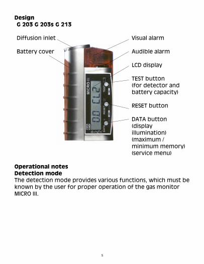
Design G 203 G 203s G 213
Diffusion inlet Visual alarm Battery cover
Audible alarm LCD display TEST button (for detector and battery capacity) RESET button DATA button (display illumination) (maximum / minimum memory) (service menu)
Operational notes Detection mode The detection mode provides various functions, which must be known by the user for proper operation of the gas monitor MICRO III.
5

Turning on Turn the MICRO III on before you enter a possibly confined area. Only this makes sure that accidents caused by gas hazards are prevented. For turning on put the battery in or, if it is already fit, press button . Turn on (initial) Insert battery
Press button Turn on
At first stage the MICRO III checks, if a valid sensor is fit, and if not, the rear LED flashes. The display reads SENS.ERR. This fault report is indicated until a valid sensor is plugged in. Then the MICRO III does a complete self-check. Both LEDs light up shortly, and the buzzer sounds for approximately 1 second. The battery capacity is displayed as well (see check of battery capacity). The warm-up time of the sensor is indicated by an audible signal every second, and the display reads a countdown (only for the initial activation). Once the self-check is completed, the MICRO III turns to detection mode. The LCD display indicates the gas and the concentration, e.g.:
0.0 PPM alternating 0.0 CL2 Display Depending on the parameter setting, either a visual or an audible confidence beep in regular intervals is activated during the detection mode. This signal proves that the detector is ready for operation. You can choose between a visual and an audible signal (see confidence beep).
6
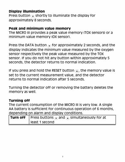
Display illumination Press button shortly to illuminate the display for approximately 8 seconds. Peak and minimum value memory The MICRO III provides a peak value memory (TOX sensors) or a minimum value memory (OX sensor). Press the DATA button for approximately 2 seconds, and the display indicates the minimum value measured by the oxygen sensor respectively the peak value measured by the TOX sensor. If you do not hit any button within approximately 5 seconds, the detector returns to normal indication. If you press and hold the RESET button , the memory value is set to the current measurement value, and the detector returns to normal indication after 5 seconds. Turning the detector off or removing the battery deletes the memory as well.
Turning off The current consumption of the MICRO III is very low. A single AA battery is sufficient for continuous operation of 6 months, depending on alarm and display conditions. Turn off Press buttons and simultaneously for at
least 1 second
7

Alarm Should the gas concentration exceed a pre-set threshold, a visual and audible alarm is triggered immediately. The MICRO III provides 3 alarm thresholds:
Detectors for: Description Alarm thresholds
AL 1 Alarm 1, exceeding s
AL 2 Alarm 2, exceeding s Toxic gases
AL 3 Alarm 3, exceeding s
AL 1 Alarm 1, falling below t
AL 2 Alarm 2, falling below t Oxygen
AL 3 Alarm 3, falling below s The thresholds AL1, AL2, and AL 3 stand for instantaneous concentration alarms. Alarm signals The alarms are distinguished by means of different flash and sound frequencies of the visual and audible alarm signals:
Audible and visual alarm
Alarm Alarm signal Priority
AL 1 Slow sound and flash frequency
Low 2 x 2 x ...
AL 2 Medium sound and flash frequency 4 x 4 x ... Medium
AL 3 Fast sound and flash frequency 8 x 8 x ... High
The LCD display indicates the gas and the alarm threshold, e.g.
Display alternating 7.5 CL2 7.5 AL2
8

Special notes for oxygen monitoring and SOSour gases like CO2 2 are easily absorbed by the
electrolyte of the oxygen sensor. This results in an increased oxygen signal of e.g. approximately 0.3 % of the measurement value per 1 Vol.-% CO2. The oxygen sensor, therefore, cannot be recommended for continuous measurement in concentrations above 25 Vol.-% CO2. If the carrier gas is a gas with a molecular weight, which is different from that for nitrogen, the display values may also be incorrect. There are no cross sensitivities of the oxygen sensor for toxic gas concentrations within the TLV range. Battery The MICRO III is powered by one 1.5 V AA battery (mignon). This battery allows a continuous operation of up to 6 months. The operational time may be reduced by frequent alarms, by display indication or by activated confidence beep. The correct battery type is: Duracell MN 1500 LR6 Battery alarm The MICRO III monitors the battery voltage permanently and gives a warning, if it falls below the minimum voltage, which is equivalent to approximately 5 % of the battery capacity. A battery alarm is indicated by an audible warning. Audible battery alarm Alarm signal
Fast sound frequency (2 strokes)
2 x 6 seconds pause 2 x. . . .
The LCD display indicates the battery capacity “XX bAT”, e.g.
Display 5 bAT
9

The remaining capacity after the first battery alarm allows detection for at least another 15 minutes. For safe operation, the battery is to be replaced as soon as possible. Should the battery voltage become so low that proper functioning is no longer possible, the detector turns off automatically. The display reads bAT. EMPTY. This reading is shown until the battery is replaced or until the battery is discharged completely. Battery replacement (only in safe area, resp. outside of Ex-areas) Note: The Duracell MN 1500, LR 6 battery must be inserted
or replaced in safe areas only. Take care of the correct polarity when fitting the battery (fit the plus pole first). Once the battery is fit, the MICRO III effects a self-check, testing the visual and audible alarms.
Slide battery coverto the top
Replace battery
For battery replacement slide the battery cover to the top. Then take the old battery out and replace it by a new one. Note: • Use only Ex-proof batteries in
hazardous areas! • Watch out for the correct polarity
of the new battery! • Fit battery with + pole first!
10
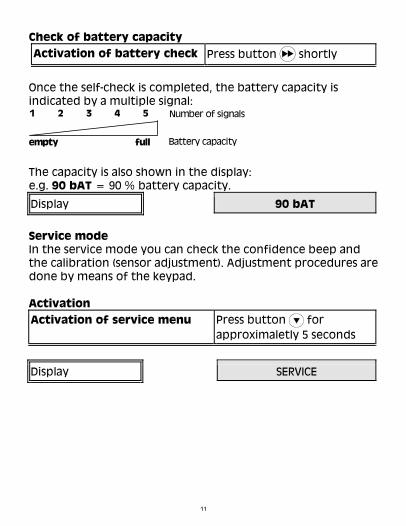
Check of battery capacity
Activation of battery check Press button shortly
Once the self-check is completed, the battery capacity is indicated by a multiple signal: 1 2 3 4 5
empty full
Number of signals
Battery capacity The capacity is also shown in the display: e.g. 90 bAT = 90 % battery capacity.
Display 90 bAT
Service mode In the service mode you can check the confidence beep and the calibration (sensor adjustment). Adjustment procedures are done by means of the keypad. Activation
Press button for approximaletly 5 seconds
Activation of service menu
Display SERVICE
11

Once you activated the service menu, you can select the individual menu points one after the other by shortly pressing button . These menu points are:
Confidence beep
Sensor adjustment with fresh air
Sensor adjustment with test gas
The individual menu points are characterized by a certain display readout as shown below:
Button Menu point
Oxygen sensor TOX sensor
bEEP ON bEEP ON
or or
bEEP OFF bEEP OFF
AUTO - CAL AUTO - ZPT
AUTO - ZPT AUTO - CAL
Sensor adjustment with fresh air
Sensor adjustment with test gas
Display
Confidence beep
Press the RESET button to leave every menu point without changing its setting. For the procedures below you must have selected the relevant menu point:
12

Confidence beep In the standard setting the alternating display of gas and unit indicates that the detector is operated in detection mode. An additional confidence beep can be activated, reminding the user in regular intervals that the detector is working. The confidence beep interval is 1 minute. The audible signal can also be turned off again.
Display in service menu
Visual Standard setting alternating indication of gas and unit in
display bEEP OFF
Visual Audible Confidence beep alternating indication of gas
and unit in display bEEP ON
short after changing
For activation/deactivation of the confidence beep adhere to the following procedure:
Button Audible confidence beep
Turn on Turn off
bEEP OFF bEEP ON Display reading Display reading
bEEP OFF bEEP ON
Display reading
Display reading
Beep long
Then the detector automatically returns to detection mode.
13

Sensor adjustment with fresh air The “fresh air adjustment” sets the MICRO III in clean ambient air to its nominal value, which is 0 ppm for toxic gases (e.g. CO, H2S) and 20.9 Vol.-% for oxygen. This means, that for toxic gas sensors the zero point is adjusted, while for oxygen the sensitivity is calibrated.
Button
Reading during calibration
Fault indicationLED flashing in high
frequencyERROR
Reading after successful calibration STORE
Reset of fault indication
Press RESET button
LED flashing in high frequency
ERROR
3 x beep STORE
alternating
0.0 ZPT
LED flashing[VALUE] CL2
3 x beep
LED flashing[VALUE] O2
alternating
20.9 CAL
AUTO-ZPTDisplay reading for TOX
sensors
AUTO-CALDisplay reading for oxygen
sensor
Sensor adjustment with fresh air
Oxygen sensor TOX sensor
During the fresh air adjustment the LED flashes in short intervals as long as the gas concentration is checked. The display reads the current measurement value and the kind of
14

gas and, alternating, CAL or ZPT. Successful adjustment is indicated by three buzzer signals and by STORE in the display. Should the detector notice a fault during the adjustment, the LED flashes in a high frequency, and the display reads ERROR. Potential faults are a faulty sensor or a gas concentration, which is beyond the valid tolerance. In such cases please call GfG service. Press the RESET button to acknowledge the fault indication. Once the adjustment is completed successfully, the MICRO III returns to detection mode. Sensor adjustment with test gas The test gas adjustment sets the MICRO III to a gas specific nominal value. This means that for toxic gas sensors the sensitivity is calibrated, while for the oxygen sensor the zero point is adjusted. For toxic gas sensors make sure that the fresh air adjustment is effected is effected before calibration. Now you need the correct test gas. Test gases are: For toxic gases, e.g. carbon monoxide (CO), hydrogen sulfide (H2S), etc. For the correct test gas please refer to the test report of your detector.
). For oxygen 100 Vol.-% nitrogen (N2
Calibration procedure:
Put the calibration adapter over the diffusion inlet of the MICRO III. For avoiding mistakes in calibration make sure that the MICRO III is exposed to a constant test gas flow for approximaletly 3 minutes. The flow rate should be 0.5...0.6 l/min.
15

Button
Oxygen sensor TOX sensor
AUTO-ZPT AUTO-CAL
Display for oxygen sensor
Display for TOX sensors
LED flashing LED flashing[VALUE] O2 [VALUE] CL2
alternating alternating
00.0 ZPT 3.0* CAL
3 x beep 3 x beepSTORE STORE
LED flashing in high frequency
LED flashing in high frequency
ERROR ERROR
Reset of fault indication
Press RESET button
Fault indication
Display during calibration
* test gas concentration
Display after successful calibration
Sensor adjustment with test gas
The display readings during and after the test gas calibration are the same as for the fresh air adjustment. Once the sensitivity calibration is completed successfully, the MICRO III returns to detection mode automatically.
16

Sensor replacement
Note: Sensors may only be replaced in safe areas.
Before an expert replaces the sensor, the battery must be removed as described above. Slide the battery cover off the casing completely. Now pull the sensor out and replace it by a new one. With the exception of the model G 201 all detectors allow connecting any sensor from the relevant line. Finally re-fit battery and battery cover.
Note: An error message may appear in the display, if the
O-ring (sensor seal) is missing. In this case you have to replace the rubber ring.
ERROR
Adjustment by means of configuration program The optional configuration program allows to connect the MICRO III to a PC by means of an adapter and to change the settings below: • Alarm thresholds • Alarm activation and deactivation • Deactivation of sensor adjustment in air or with test gas • Calibration gas concentration • Time interval of confidence beep (6 to 90 seconds). Annex Cleaning Give the MICRO III a short sight check after use. Use a damp cloth to remove stains or soiling from the casing. Never use solvents or cleaning agents!
17

Service and repair Service stands for maintenance, inspection, and repair of gas warning equipment. The function test must be done at least once a year and checks: • The charge status of the battery • The indication and, if necessary, the adjustment with zero
gas and standard test gas • The activation of gas alarms, e.g. With alarm test gas • The response time This test has to be done by an expert, and a written confirmation must be filed. In case of repairs, only genuine spare parts are to be used, and the manufacturer’s instructions have to be adhered to. Maintenance and inspection Maintenance and inspection describe those measures, which retain the nominal status of the MICRO III. They include a regular check and adjustment of sensitivity and zero point. In addition to this, the working order of the detector is to be checked as well. Make the MICRO III pass a test before it is being used. This test checks: • The charge status of the battery, • The display with zero gas and with test gas, • The activation of gas alarms.
18

Accessories
Description Part No.
Leather case 1318206
Calibration adapter including magnet 1318202
Configuration software with adapter cable for PC 1318203
Magnet for reed contact (G201, G202, G 212) 1318204
AQUA-SHIELD splash water protection (pack of 15) 1318205 Spare parts
Description Part No.
1. Battery Duracell MN 1500 LR6 1318201
2. Battery cover 1318315
3. Filter (PTFE) for sensor protection (pack of 10) 1318310
4. O-ring for filter (pack of 10) 1318311 Continuation of spare parts
19
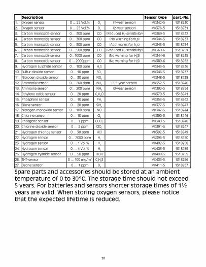
Description Sensor type part.-No. 1. Oxygen sensor 0 ... 25 Vol.% O (1-year sensor) MK342-5 1318230 2
2. Oxygen sensor 0 ... 25 Vol.% O (2-year sensor) MK376-5 1318231 2
3. Carbon monoxide sensor 0 ... 300 ppm CO (Reduced H2-sensitivity) MK369-5 1318232
4. Carbon monoxide sensor 0 ... 300 ppm CO (No warning forh2s) MK344-5 1318233
5. Carbon monoxide sensor 0 ... 300 ppm CO (Add. warns for h2s) MK343-5 1318234
6. Carbon monoxide sensor 0 ... 500 ppm CO (Reduced H2-sensitivity) MK369-6 1318251
7. Carbon monoxide sensor 0 ..1000 ppm CO (No warning for H2S) MK344-6 1318235
8. Carbon monoxide sensor 0 ... 2000ppm CO (No warning for H2S) MK389-6 1318252
9. Hydrogen sulphide sensor 0 ... 100 ppm H2S MK345-5 1318236
10. Sulfur dioxide sensor 0 ... 10 ppm SO MK346-5 1318237 2
11. Nitrogen dioxide sensor 0 ... 30 ppm NO MK348-5 1318238 2
12. Ammonia sensor 0 ... 200 ppm NH (1,5-year sensor) MK352-5 1318240 3
13. Ammonia sensor 0 ... 200 ppm NH (3-year sensor) MK393-5 1318254 3
14. Ethylene oxide sensor 0 ... 20 ppm C2H4O MK379-5 1318241
15. Phosphine sensor 0 ... 10 ppm PH MK353-5 1318242 3
16. Silane sensor 0 ... 20 ppm SiH MK377-5 1318243 4
17. Nitrogen monoxide sensor 0 ... 100 ppm NO MK347-5 1318244
18. Chlorine sensor 0 ... 10 ppm Cl MK390-5 1318246 2
19. Phosgene sensor 0 … 1 ppm COCl MK349-5 1318248 2
20. Chlorine dioxide sensor 0 … 2 ppm ClO MK391-5 1318247 2
21. Hydrogen chloride sensor 0 ... 30 ppm HCl MK392-5 1318249
22. Hydrogen sensor 0 ... 2000 ppm H MK396-5 1318250 2
23. Hydrogen sensor 0 … 1 Vol.% H MK402-5 1318258 2
24. Hydrogen sensor 0 … 4 Vol.% H MK403-5 1318259 2
25. Hydrogen cyanide sensor 0 ... 50 ppm HCN MK409-5 1318255
26. THT-sensor 0 ... 100 mg/m3 C4H8S MK405-5 1318256
27. Ozone sensor 0 … 1 ppm O MK411-5 1318257 3
Spare parts and accessories should be stored at an ambient temperature of 0 to 30°C. The storage time should not exceed 5 years. For batteries and sensors shorter storage times of 1½ years are valid. When storing oxygen sensors, please notice that the expected lifetime is reduced.
20

Types of sensors and detection range Sensor Detection
range Resolutio
n Gas T-Band *
type (ID) MK342-5 0 ... 25 Vol.% O Oxygen 0,1 Vol.% ±0,3 Vol.% 2
MK343-5 0 ... 300 ppm CO Carbon monoxide 1 ppm ±3 ppm MK344-5 0 ... 300 ppm CO Carbon monoxide 1 ppm ±3 ppm MK344-6 0 ... 1000 ppm CO Carbon monoxide 1 ppm ±5 ppm MK345-5 0 ... 100 ppm H2S Hydrogen sulphide 1 ppm ±1 ppm MK346-5 0 ... 10 ppm SO Sulphur dioxide 0,1 ppm ±0,3 ppm 2
MK347-5 0 ... 100 ppm NO Nitrogen monoxide 1 ppm ±3 ppm MK348-5 0 ... 30 ppm NO Nitrogen dioxide 0,2 ppm ±0,6 ppm 2
MK349-5 0 ... 1 ppm COCl Phosgene 0,01 ppm ±0,02 ppm2
MK352-5 0 ... 200 ppm NH Ammonia 1 ppm ±3 ppm 3
MK353-5 0 ... 10 ppm PH Phosphine 0,05 ppm ±0,05 ppm3
MK369-5 0 ... 300 ppm CO Carbon monoxide 1 ppm ±3 ppm MK369-6 0 ... 500 ppm CO Carbon monoxide 1 ppm ±4 ppm MK376-5 0 ... 25 Vol.% O Oxygen 0,1 Vol.% ±0,3 Vol.% 2
MK377-5 0 ... 20 ppm SiH Silane 0,05 ppm ±0,10 ppm4
MK379-5 0 ... 20 ppm C2H4O Ethylene oxide 0,1 ppm ±0,3 ppm MK389-6 0 ... 2000 ppm CO Carbon monoxide 1 ppm ±4 ppm MK390-5 0 ... 10 ppm Cl Chlorine 0,1 ppm ±0,1 ppm 2
MK391-5 0 ... 2 ppm ClO Chlorine dioxide 0,01 ppm ±0,03 ppm2
* T-Band = tolerance-band Sensor type (ID)
Detection range
Gas Resolution T-Band *
MK392-5 0 .. 30 ppm HCl Hydrogen chloride 0,2 ppm ±0,4 ppm MK393-5 0 .. 200 ppm NH Ammonia 1 ppm ±3 ppm 3
MK396-5 0 .. 2000 ppm H Hydrogen 2 ppm ±10 ppm 2
MK402-5 0 .. 1 Vol.% H Hydrogen 0,01 Vol.% ±0,02 Vol.% 2
MK403-5 0 .. 4 Vol.% H Hydrogen 0,01 Vol.% ±0,05 Vol.% 2
THT (Tetrahydrothiophen) MK405-5 0 .. 100 mg/m3 C4H8S 0,5 mg/m3 ±1,0 mg/m3
MK409-5 0 .. 50 ppm HCN Hydrogen cyanide 0,5 ppm ±1,5 ppm MK411-5 0 .. 1 ppm O Ozone 0,01 ppm ±0,02 ppm 3
* T-Band = tolerance-band
21
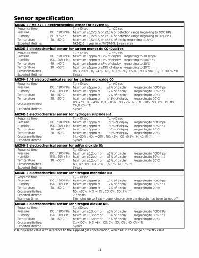
Sensor specification MK342-5 / MK 376-5 electrochemical sensor for oxygen O2
Response time T : <10 sec T : <20 sec 20 90
Pressure 800...1200 hPa: Maximum ±0,2Vol.% or ±2,5% of detection range (regarding to 1000 hPa) Humidity 0%...99% r.h.: Maximum ±0,2Vol.% or ±2,5% of detection range (regarding to 50% r.h.)
Maximum ±0,5Vol.% or ±2,5% of display (regarding to 20°C) Temperature -20...+50°C: Expected lifetime: MK342-5: 1 year in air/MK376-5: 2 years in air
MK343-5 electrochemical sensor for carbon monoxide CO (DualTox) Response time T : <10 sec T : <40 sec 20 90
Pressure 800...1200 hPa: Maximum ±3ppm or ±7% of display (regarding to 1000 hpa) Humidity 15%...90% r.h.: Maximum ±3ppm or ±7% of display (regarding to 50% r.h.)
Maximum ±3ppm or ±7% of display (regarding to 20°C) Temperature -10...+40°C: Maximum ±3ppm or ±15% of display (regarding to 20°C) Temperature -20...+50°C:
Cross sensitivities: H2S: ≈ 250% , H2: <40% , NO2: ≈-60% , SO2: ≈ 50% , NO: ≈ 30% , Cl2: 0..-100% (*1) Expected lifetime: 3 years
MK344-5 /-6 electrochemical sensor for carbon monoxide CO Response time T : <10 sec T : <40 sec 20 90
Pressure 800...1200 hPa: Maximum ±3ppm or ±7% of display (regarding to 1000 hpa) Humidity 15%...90% r.h.: Maximum ±3ppm or ±7% of display (regarding to 50% r.h.)
Maximum ±3ppm or ±7% of display (regarding to 20°C) Temperature -10...+40°C: Maximum ±3ppm or ±15% of display (regarding to 20°C) Temperature -20...+50°C:
Cross sensitivities: H2S: ≈7% , H2: <40% , C2H4: <85% , NO: <9% , NO2: 0...-20% , SO2: 0% , Cl2: 0% , C2H60: 0% (*1)
Expected lifetime: 3 years
S MK345-5 electrochemical sensor for hydrogen sulphide H2
Response time T : <10 sec T : <40 sec 20 90
Pressure 800...1200 hPa: Maximum ±3ppm or ±10% of display (regarding to 1000 hpa) Humidity 15%...90% r.h.: Maximum ±3ppm or ±10% of display (regarding to 50% r.h.)
Maximum ±3ppm or ±10% of display (regarding to 20°C) Temperature -10...+40°C: Maximum ±3ppm or ±15% of display (regarding to 20°C) Temperature -20...+50°C:
Cross sensitivities: SO2: ≈20% , NO2: ≈-20% , NO: <2% , CO: <0,5% , H2 <0,1% (*1) Expected lifetime: 3 years
MK346-5 electrochemical sensor for sulfur dioxide SO2
Response time T : <30 sec 90
Pressure 800...1200 hPa: Maximum ±0,2ppm or ±5% of display (regarding to 1000 hpa) Humidity 15%...90% r.h.: Maximum ±0,2ppm or ±5% of display (regarding to 50% r.h.)
Maximum ±0,2ppm or ±5% of display (regarding to 20°C) Temperature -20...+50°C: Cross sensitivities: NO2: ≈-100% , CO: <1% , H2S: 0% , NO: 0% (*1) Expected lifetime: 3 years
MK347-5 electrochemical sensor for nitrogen monoxide NO Response time T : <30 sec 90
Pressure 800...1200 hPa: Maximum ±1ppm or ±7% of display (regarding to 1000 hpa) Humidity 15%...90% r.h.: Maximum ±1ppm or ±7% of display (regarding to 50% r.h.)
Maximum ±2ppm or ±7% of display (regarding to 20°c) Temperature -20...+50°C: Cross sensitivities: NO2: <30% , H2S: ≈10% , CO: 0% , SO2: 0% (*1) Expected lifetime: 2..3 years Warm-up time: 3 minutes up to 1 day – depending on time the detector has been turned off
MK348-5 electrochemical sensor for nitrogen dioxide NO2
Response time T : <30 sec 90
Pressure 800...1200 hPa: Maximum ±0,3ppm or ±5% of display (regarding to 1000 hPa) Humidity 15%...90% r.h.: Maximum ±0,3ppm or ±5% of display (regarding to 50% r.h.)
Maximum ±0,3ppm or ±5% of display (regarding to 20°C) Temperature -20...+50°C: Cross sensitivities: Cl2: ≈100% , H2S: ≈8% , CO: 0% , SO2: 0% , NO: 0% (*1) Expected lifetime: 3 years
(*1): Displayed value with reference to the supplied gas concentration, which lies in the range of the TLV value
22

MK349-5 electrochemical sensor for phosgene COCl2
Response time T : <150 sec 90
Pressure 800...1200 hPa: Maximum ±0,02ppm or ±10% of display (regarding to 1000 hPa) Humidity 10%...95% r.h.: Maximum ±0,02ppm or ±10% of display (regarding to 50% r.h.)
Maximum ±0,02ppm or ±10% of display (regarding to 20°C) Temperature -20...+40°C: CCross sensitivities: 2H6O=CO2=CO=Cl2=H2=HF=PH3=SO2: 0% HCN=H2S: 0% (poisoning if exposure to gas for a longer time) (*1)
Expected lifetime: 1..1,5 years
MK352-5 electrochemical sensor for ammonia NH3
Response time T : <150 sec 90
Pressure 800...1200 hPa: Maximum ±5ppm or ±10% of display (regarding to 1000 hPa) Humidity 15%...90% r.h.: Maximum ±5ppm or ±10% of display (regarding to 50% r.h.)
Maximum ±5ppm or ±10% of display (regarding to 20°C) Temperature -20...+40°C:
Cross sensitivities: H2S: ≈100% , SO2: ≈80% , Cl2: ≈-50% , NO: ≈20% , HCN: ≈5% , CO= HCL=NO2=H2= C2H4: 0% (*1)
Expected lifetime: 1..1,5 years in air resp. 2ppm years Warm-up time: 4 minutes up to 5 days - depending on time the detector has been turned off
MK353-5 electrochemical sensor for phosphine PH3
Response time T : <90 sec 90
Pressure 800...1200 hPa: Maximum ±0,05ppm or ±10% of display (regarding to 1000 hPa) Humidity 15%...90% r.h.: Maximum ±0,05ppm or ±10% of display (regarding to 50% r.h.)
Maximum ±0,05ppm or ±10% of display (regarding to 20°C) Temperature -20...+50°C:
Cross sensitivities: H2: ≈3% , SO2: ≈20% , SiH4: ≈90% , GeH4: ≈85% , B2H6: ≈35% , AsH3: 0% , C2H4: <2% , CO: <0,1% (*1)
Expected lifetime: 2..3 years
MK369-5 /-6 electrochemical sensor for carbon monoxide CO Response time T : <10 sec T : <30 sec 20 90
Pressure 800...1200 hPa: Maximum ±3ppm or ±10% of display (regarding to 1000 hPa) Humidity 15%...90% r.h.: Maximum ±3ppm or ±10% of display (regarding to 50% r.h.)
Maximum ±3ppm or ±15% of display (regarding to 20°C) Temperature -20...+50°C: Cross sensitivities: H2: <10% , NO: <9% , H2S: 0% , SO2: 0% (*1) Expected lifetime: 2..3 years
MK377-5 electrochemical sensor for silane SiH4
Response time T : <70 sec 90
Pressure 800...1200 hPa: Maximum ±0,1ppm or ±10% of display (regarding to 1000 hPa) Humidity 15%...90% r.h.: Maximum ±0,1ppm or ±10% of display (regarding to 50% r.h.)
Maximum ±0,1ppm or ±10% of display (regarding to 20°C) Temperature -20...+50°C:
Cross sensitivities: PH3: ≈110% , GeH4: ≈95% , AsH3: ≈90% , B2H6: ≈40% , SO2: ≈20% , C2H4: ≈2% , CO: <1% , H2: <0,05% (*1)
Expected lifetime: 2..3 years
O MK379-5 electrochemical sensor for ethylene oxide C H2 4
Response time T : <120 sec 90
Pressure 800...1200 hPa: Maximum ±1ppm or ±15% of display (regarding to 1000 hPa) Humidity 15%...90% r.h.: Maximum ±2ppm or ±15% of display (regarding to 50% r.h.) Temperature 0...+30°C: -20...+50°C:
Maximum ±1ppm or ±15% of display (regarding to 20°C) Maximum ±2ppm or ±20% of display (regarding to 20°C) CO: ≈40% , CHCross sensitivities: 4O: ≈50% , C2H2: ≈125% , CH2O: ≈120% , CH4S: ≈100% , C2H4: ≈80% , C2H6O: ≈55% , C7H8: ≈20% , MEK: ≈10% u.a. (*1)
Expected lifetime: 2..3 years Warm-up time: 4 minutes up to 7 days – depending on time the detector has been turned off
MK389-6 electrochemical sensor for carbon monoxide CO Response time T : <10 sec T : <30 sec 20 90
Pressure 800...1200 hPa: Maximum ±3ppm or ±7% of display (regarding to 1000 hPa) Humidity 15%...90% r.h.: Maximum ±3ppm or ±7% of display (regarding to 50% r.h.)
Maximum ±3ppm or ±7% of display (regarding to 20°C) Temperature -10...+40°C: Maximum ±3ppm or ±15% of display (regarding to 20°C) Temperature -20...+50°C:
Cross sensitivities: H2: ≈25% , NO: ≈25% , H2S=NO2=SO2=CO2= Cl2=NH3: 0% (*1) Expected lifetime: 3..4 years
23

MK390-5 electrochemical sensor for chlorine Cl2
Response time T : <30 sec 90
Pressure 800...1200 hPa: Maximum ±0,2ppm or ±10% of display (regarding to 1000 hPa) Humidity 10%...95% r.h.: Maximum ±0,2ppm or ±10% of display (regarding to 50% r.h.)
Maximum ±0,2ppm or ±10% of display (regarding to 20°C) Temperature -20...+50°C: Cross sensitivities: F2: ≈44% , ClO2: ≈20% , NO2: ≈12% , H2S: ≈-3% , HCl: <2% , CO: 0% , SO2: 0% (*1) Expected lifetime: 2..3 years
MK391-5 electrochemical sensor for chlorine dioxide ClO2
Response time T : <120 sec 90
Pressure 800...1200 hPa: Maximum ±0,05ppm or ±10% of display (regarding to 1000 hPa) Humidity 10%...95% r.h.: Maximum ±0,05ppm or ±10% of display (regarding to 50% r.h.)
Maximum ±0,05ppm or ±10% of display (regarding to 20°C) Temperature -20...+50°C:
Cross sensitivities: Cl2: ≈90% , H2S: ≈-0,2% , H2=CO2=CO=GeH4=B2H6: 0% , available but not defined: NO2
, O3 and F2 (*1) Expected lifetime: 1..2 years
MK393-5 electrochemical sensor for ammonia NH3
Response time T : <60 sec 90
Pressure 800...1200 hPa: Maximum ±1ppm or ±10% of display (regarding to 1000 hPa) Humidity 10%...95% r.h.: Maximum ±1ppm or ±10% of display (regarding to 50% r.h.)
Maximum ±1ppm or ±15% of display (regarding to 20°C) Temperature -20...+50°C: CO: 0% , COCross sensitivities: 2: 0% , H2: 0% , C2H6O: 0% , Cl2: 0% , HCN: 0% , N2: 0% , H2S: 0% (in minute range) (*1)
Expected lifetime: 2..3 years (*1): Displayed value with reference to the supplied gas concentration, which lies in the range of the TLV value.
(*2) MK396-5 electrochemical sensor for hydrogen H2
Response time T : <90 sec 90
Pressure 800...1200 hPa: Maximum ± 5ppm or ±10% of display (regarding to 1000 hPa) Humidity 15%...90% r.h.: Maximum ± 5ppm or ±10% of display (regarding to 50% r.h.)
Maximum ±10ppm or ±20% of display (regarding to 20°C) Temperature -20...+50°C:
Cross sensitivities: CO: <20% , H2S: <20% , NO: ≈30% , HCN: ≈30% , SO2: 0% , NO2: 0% , Cl2: 0% , HCl: 0% , C2H4: ≈80% (*1)
Expected lifetime: 2..3 years
(*2) MK402-5 electrochemical sensor for hydrogen H2
Response time T : <90 sec 90
Pressure 800...1200 hPa: Maximum ±0,01Vol.% or ±10% of display (regarding to 1000 hPa) Humidity 10%...90% r.h.: Maximum ±0,01Vol.% or ±10% of display (regarding to 50% r.h.)
Maximum ±0,02Vol.% or ±20% of display (regarding to 20°C) Temperature -20...+50°C: Cross sensitivities: CO: <15% , Cl2: ≈80% (*1) Expected lifetime: 2..3 years
(*2) MK403-5 electrochemical sensor for hydrogen H2
Response time T : <90 sec 90
Pressure 800...1200 hPa: Maximum ±0,01Vol.% or ±10% of display (regarding to 1000 hPa) Humidity 10%...90% r.h.: Maximum ±0,01Vol.% or ±10% of display (regarding to 50% r.h.)
Maximum ±0,02Vol.% or ±25% of display (regarding to 20°C) Temperature -20...+50°C: Cross sensitivities: CO: <15% (*1) Expected lifetime: 2..3 years
S MK405-5 electrochemical sensor for tetrahydrothiophen (THT) C H4 8
Response time T : <30 sec 903 or ±10% of display (regarding to 1000 hPa) Pressure 800...1200 hPa: Maximum ±1mg/m3 or ±10% of display (regarding to 50% r.h.) Humidity 10%...95% r.h.: Maximum ±1mg/m3 or ±15% of display (regarding to 20°C) Maximum ±2mg/mTemperature -10...+45°C:
Cross sensitivities:
CO2: 0% 4mg/m at3 1000ppmCO 150mg/m3 at 1Vol.% H2 2mg/m3 at 2ppmSO2
216mg/m3 at 1300ppm CH4O 3mg/m3 at 10ppm NO2
Expected lifetime: 2 years Warm-up time: 4 minutes up to 3 days - depending on time the detector has been turned off
24
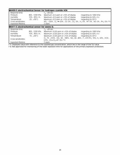
MK409-5 electrochemical Sensor for hydrogen cyanide HCN Response time T : <60 sec 90
Pressure 800...1200 hPa: Maximum ±0,5 ppm or ±10% of display (regarding to 1000 hPa) Humidity 10%...95% r.h.: Maximum ±0,5 ppm or ±10% of display (regarding to 50% r.h.)
Maximum ±0,5 ppm or ±15% of display (regarding to 20°C) Temperature -20...+50°C: Cross sensitivities: NO2: -120% , Cl2: ••-20% , CO: 0% , CO2: 0% , H2: 0% , HF: 0% , NO: 0% , PH3: 0% (*1)Expected lifetime: 2 years
MK411-5 electrochemical sensor for ozone O3
Response time T : <60 sec 90
Pressure 800...1200 hPa: Maximum ±0,03 ppm or ±10% of display (regarding to 1000 hPa) Humidity 10%...95% r.h.: Maximum ±0,03 ppm or ±10% of display (regarding to 50% r.h.)
Maximum ±0,03 ppm or ±15% of display (regarding to 20°C) Temperature -10...+45°C:
Cross sensitivities: Cl2: 70…210% , ClO2: 60…180% , NO2: 60...80% , F2: ≈70 PH3: 10%, H2: ≈0% , HCN: -0,3% , CO=CO2=HF: 0% (*1)
Expected lifetime: 2 years (*1): Displayed value with reference to the supplied gas concentration, which lies in the range of the TLV value. (*2): Not approved for monitoring of the lower explosion limit for applications of the primary explosion protection.
25

Alarm thresholds-standard settings and test gas chart Germany:
Instantaneous alarms following to TRGS 900 (Version 2000) Detection range Alarm 1 Alarm 2 Alarm 3 Cal.-Gas
1. 1,00/4,00 Vol.% H Hydrogen (*2) 0,20 (*2) 0,40 (*2) 0,60 (*2) 1,00 2
2. 25 Vol.% O Oxygen 19,0 17,0 23,0 20,9 2
3. 300/500 ppm CO Carbon monoxide 30 60 300 200 4. 100 ppm H2S Hydrogen sulphide 10 20 100 20 5. 100 ppm NO Nitrogen monoxide 25 50 100 100 6. 200 ppm NH3 Ammonia 50 100 200 100 7. 50,0 ppm HCN Hydrogen cyanide 10,0 20,0 50,0 50,0 8. 30,0 ppm HCl Hydrogen chloride 5,0 10,0 30,0 10,0 9. 10,0 ppm SO2 Sulphur dioxide 2,0 4,0 10,0 10,0 G
201, G
202, G
203
1. 2000 ppm H Hydrogen (*2) 1000 (*2) 1500 (*2) 2000 (*2) 1000 2
2. 25,0 Vol.% O Oxygen 19,0 17,0 23,0 20,9 2
3. 1000/2000 ppm CO Carbon monoxide 30 60 300 400 4. 100 ppm H2S Hydrogen sulphide 10 20 100 50 5. 20,0 ppm C2H4O Ethylene oxide 2,0 (*3) 4,0 20,0 20,0 6. 20,00 ppm SiH4 Silane 5,00 10,00 20,00 5,00 7. 10,00 ppm PH3 Phosphine 0,30 (*3) 0,40 (*3) 10,00 5,00 8. 1,00 ppm COCl2 Phosgene 0,10 (*3) 0,20 (*3) 1,00 1,00 G
202s,
G 2
03s
THT (Tetrahydrothiophen) 9. 100,0 mg/m3 C H S 25,0 50,0 100,0 37,0 4 8
1. 30,0 ppm NO Nitrogen dioxide 5,0 10,0 30,0 20,0 2
2. 10,0 ppm Cl2 Chlorine 0,5 1,0 10,0 5,0 3. 1,00 ppm O3 Ozone 0,10 0,20 1,00 0,70 4. 2,00 ppm ClO2 Chlorine dioxide 0,10 0,20 1,00 1,00
G 2
12, G
213
(*2): Not approved for monitoring of the lower explosion limit for applications of the primary explosion protection. (*3): A reliable TLV (threshold limit value) monitoring is not possible with the sensor technology currently available.
26

USA: Detection range Alarm 1 Alarm 2 Alarm 3 Cal.-Gas
1. 1,00/4,00 Vol.% H Hydrogen (*2) 0.20 (*2) 0.40 (*2) 0.60 (*2) 1.00 2
2. 25 Vol.% O2 Oxygen 19.5 • 17.0 • 23.5 • 20.9 3. 300/500 ppm CO Carbon monoxide 35 200 300 200 4. 100 ppm H2S Hydrogen sulphide 10 15 100 20 5. 100 ppm NO Nitrogen monoxide 25 50 100 50 6. 200 ppm NH3 Ammonia 25 50 200 100 7. 50,0 ppm HCN Hydrogen cyanide 5 10 50 50 8. 30,0 ppm HCl Hydrogen chloride 5 10 30 10 9. 10,0 ppm SO2 Sulphur dioxide 2 5 10 5 G
20
1,
G 2
02
, G
20
3
1. 2000 ppm H Hydrogen (*2) 1000 (*2) 1500 (*2) 2000 (*2) 1000 2
2. 25,0 Vol.% O Oxygen 19.5 • 17.0 • 23.5 • 20.9 2
3. 1000/2000 ppm CO Carbon monoxide 35 200 300 400 4. 100 ppm H2S Hydrogen sulphide 10 15 100 20 5. 20,0 ppm C2H4O Ethylene oxide 2 5 20 10 6. 20,00 ppm SiH4 Silane 5 10 20 5 7. 10,00 ppm PH3 Phosphine 0.3 1.0 10.0 5.0 8. 1,00 ppm COCl2 Phosgene 0.1 0.2 1.0 1.0 9. 100,0 mg/m3 C4H8S THT (Tetrahydrothiophen) 25 50 100 37
G 2
02
s, G
20
3s
1. 30,0 ppm NO Nitrogen dioxide 3 5 30 10 2
2. 10,0 ppm Cl2 Chlorine 0.5 1.0 10.0 5.0 3. 1,00 ppm O3 Ozone 0.1 0.2 1.0 0.7 4. 2,00 ppm ClO2 Chlorine dioxide 0.1 0.3 1.0 1.0
G 2
12
, G
21
3
(*2): Not approved for monitoring of the lower explosion limit for applications of the primary explosion protection.
27

Technical data Detector type: MICRO III
Detection principle: Electrochemical sensor (EC)
Detection ranges: See “type of sensors and detection ranges”
Response time T : See section “sensor specification” 90
Expected sensor life: See section “sensor specification”
Climatic effects: See section “sensor specification”
Display: LCD display with backlight illumination
Visual and audible warning 3 instantaneous concentration alarms see section “basic adjustment of alarm thresholds” Alarm:
Gas supply: Diffusion
Zero point / calibration: With calibration adapter at a flow rate of 0.5...0.6 l/min
Climate conditions:
-20...+50(40)°C / 10...95% r.h. / 700...1300hPa please also see section “sensor specification”
for operation:
for storage: -25...+55°C / 10...95% r.h. / 700...1300hPa (recomm. 0...+30°C)
Power supply: 1 AA battery (mignon), 1.5 V / Duracell MN 1500/LR6
6 months, may be reduced depending on alarm frequency and battery type
Operational time:
Casing
Casing material: Polycarbonate, metalised
Dimensions: 47 x 88 x 25 mm (WxHxD)
Weight: min. 61 g –model without display, without keypad, with CO sensor Maximum 85.6 g –model with display, with keypad, with O sensor 2
Protection: IP54
Approval:
Electromagnetic Compatibility: As per EN50270 type 2 and EN50081-1 resp. EN55022 Class B
Only when used with Duracell MN 1500, LR6 ⎯ II 2G EEx ib IIC T6 resp. T5 -20°C • TLabelling and ignition
protection: a • +50°C
For using the pump (see accessories) the detector unit is subject to the temperature classification of the Micro III pump
EC type approval: DMT 99 ATEX E 044
Production supervision: X 0158 (by named testing body - EXAM)
28


1194 Oak Valley Drive, Suite 20Ann Arbor, Michigan 48108 USA
Tel: (800) 959-0329E-mail: [email protected]: www.gfg-inc.com
Visit our new web site at www.gfg-inc.com1106 7004-203