models st2037f st2040tf - multiquip inc
TRANSCRIPT

OPERATION AND PARTS MANUAL
THIS MANUAL MUST ACCOMPANY THE EQUIPMENT AT ALL TIMES.
MODELSST2037F
ST2040TFSUBMERSIBLE PUMP WITH FLOAT SWITCH
Revision #6 (11/04/20)
To find the latest revision of this publication, visit our website at:
www.multiquip.com

PAGE 2 — ST2037F/2040TF SUBMERSIBLE PUMP • OPERATION AND PARTS MANUAL — REV. #6 (11/04/20)
PROPOSITION 65 WARNING

ST2037F/2040TF SUBMERSIBLE PUMP • OPERATION AND PARTS MANUAL — REV. #6 (11/04/20) — PAGE 3
TABLE OF CONTENTS
ST2037F/ST2040TF Submersible Pump with Float SwitchProposition 65 Warning ........................................... 2Safety Information ................................................ 4-7Specifications .......................................................... 8Dimensions .............................................................. 9General Information ............................................... 10Pump Components ................................................ 11Float Switches ....................................................... 12Installation ............................................................. 13Operation ............................................................... 14Maintenance ..................................................... 15-16Troubleshooting ..................................................... 17Performance Curve/ Wiring Diagram ..................... 18Explanation Of Code In Remarks Column............. 20Suggested Spare Parts ......................................... 21
Component DrawingsST2037F Pump Assembly ................................ 22-23ST2040TF Pump Assembly .............................. 24-25
NOTICE
Specifications and part numbers are subject to change without notice.

PAGE 4 — ST2037F/2040TF SUBMERSIBLE PUMP • OPERATION AND PARTS MANUAL — REV. #6 (11/04/20)
SAFETY INFORMATION
Do not operate or service the equipment before reading the entire manual. Safety precautions should be followed at all times when operating this equipment. Failure to read and understand the safety messages and operating instructions could result in injury to yourself and others.
SAFETY MESSAGES
The four safety messages shown below will inform you about potential hazards that could injure you or others. The safety messages specifi cally address the level of exposure to the operator and are preceded by one of four words: DANGER, WARNING, CAUTION or NOTICE.
SAFETY SYMBOLS
DANGER
Indicates a hazardous situation which, if not avoided, WILL result in DEATH or SERIOUS INJURY.
WARNING
Indicates a hazardous situation which, if not avoided, COULD result in DEATH or SERIOUS INJURY.
CAUTION
Indicates a hazardous situation which, if not avoided, COULD result in MINOR or MODERATE INJURY.
NOTICE
Addresses practices not related to personal injury.
Potential hazards associated with the operation of this equipment will be referenced with hazard symbols which may appear throughout this manual in conjunction with safety messages.
Burn hazards
Symbol Safety Hazard
Electric shock hazards
Rotating parts hazards
Pressurized fluid hazards

ST2037F/2040TF SUBMERSIBLE PUMP • OPERATION AND PARTS MANUAL — REV. #6 (11/04/20) — PAGE 5
SAFETY INFORMATION
GENERAL SAFETY
CAUTION
�NEVER operate this equipment without proper protective clothing, shatterproof glasses, respiratory protection, hearing protection, steel-toed boots and other protective devices required by the job or city and state regulations.
�Avoid wearing jewelry or loose fi tting clothes that may snag on the controls or moving parts as this can cause serious injury.
�NEVER operate this equipment when not feeling well due to fatigue, illness or when under medication.
�NEVER operate this equipment under the infl uence of drugs or alcohol.
�ALWAYS clear the work area of any debris, tools, etc. that would constitute a hazard while the equipment is in operation.
�No one other than the operator is to be in the working area when the equipment is in operation.
�DO NOT use the equipment for any purpose other than its intended purposes or applications.
NOTICE
� This equipment should only be operated by trained and qualifi ed personnel 18 years of age and older.
�Whenever necessary, replace nameplate, operation and safety decals when they become diffi cult read.
�Manufacturer does not assume responsibility for any accident due to equipment modifi cations. Unauthorized equipment modifi cation will void all warranties.
�NEVER use accessories or attachments that are not recommended by Multiquip for this equipment. Damage to the equipment and/or injury to user may result.
�ALWAYS know the location of the nearest fi re extinguisher.
�ALWAYS know the location of the nearest fi rst aid kit.
�ALWAYS know the location of the nearest phone or keep a phone on the job site. Also, know the phone numbers of the nearest ambulance, doctor and fi re department. This information will be invaluable in the case of an emergency.
PUMP SAFETY
DANGER
�NEVER operate the equipment in an explosive atmosphere or near combustible materials. An explosion or fi re could result causing severe bodily harm or even death.
WARNING
�Accidental starting can cause severe injury or death. ALWAYS place the ON/OFF switch in the OFF position.
�DO NOT place hands or fingers inside pump when pump is running.

PAGE 6 — ST2037F/2040TF SUBMERSIBLE PUMP • OPERATION AND PARTS MANUAL — REV. #6 (11/04/20)
SAFETY INFORMATION
�NEVER disconnect any emergency or safety devices. These devices are intended for operator safety. Disconnection of these devices can cause severe injury, bodily harm or even death. Disconnection of any of these devices will void all warranties.
�Risk of Electric Shock - Do not enter the pool or spa if the pump is operating.
CAUTION
�Be careful of discharge hose whipping under pressure.
�ALWAYS check pump oil level only when pump is cool. Expansion due to heat may cause hot oil to spray from the oil plug when the oil plug is removed. The possibility of severe scalding may exist.
NOTICE
�ALWAYS place the pump in an upright position on a platform before using. The platform will prevent the pump from burrowing itself on soft sand or mud. �NEVER operate pump on its side. �DO NOT allow the pump to freeze in water. �NEVER leave an open pump chamber unattended. �ALWAYS keep the machine in proper running condition. �DO NOT attempt to thaw out a frozen pump by using a torch or other source of fl ame. Application of heat in this manner may heat the oil in the seal cavity above the critical point, causing pump damage. �DO NOT pump water with a temperature greater than 140°F (60°C). �DO NOT pump liquids containing acid or alkali. �ALWAYS check strainer before pumping. Make sure strainer is not clogged. Remove any large objects, dirt or debris from the strainer to prevent clogging.
�ALWAYS use a large basket strainer when pumping water that contains large debris.
�ALWAYS fl ush pump (clean) after use when pumping water concentrated with heavy debris. It is very important to always fl ush the pump before turning it off to prevent clogging.
� Fix damage to machine and replace any broken parts immediately.
�ALWAYS store equipment properly when it is not being used. Equipment should be stored in a clean, dry location out of the reach of children and unauthorized personnel.
�NEVER lubricate components or attempt service on a running machine.
�NEVER run pump dry.
�ALWAYS allow the machine a proper amount of time to cool before servicing.
�Keep machine in proper running condition.
ELECTRICAL SAFETY
DANGER
� The electrical voltage required to operate pump can cause severe injury or even death through physical contact with live circuits. ALWAYS disconnect electrical power from pump before performing maintenance on pump.
WARNING
� To reduce the risk of electric shock, connect to a circuit protected by a Ground-Fault Circuit-Interrupter (GFCI).
�Risk of Electric Shock - This pump is supplied with a grounding conductor and grounding-type attachment plug. To reduce the risk of electric shock, be certain that it is connected only to a properly grounded, grounding-type receptacle.
AVERTISSEMENT
�Risques de chocs électriques. Cette pompe est alimentée en électricité au moyen d'un conducteur et d'une fi che d'alimentation de terre. Afi n de réduire les risques de chocs électriques, s'assurer que la pompe est uniquement connectée à des boîters de protection de mise à la terre correctement enterrés.
NOTICE
�ALWAYS make certain that the voltage supplied to the pump is correct. Always read the pump’s nameplate to determine what the power requirements are.

ST2037F/2040TF SUBMERSIBLE PUMP • OPERATION AND PARTS MANUAL — REV. #6 (11/04/20) — PAGE 7
SAFETY INFORMATION
Power Cord/Cable Safety
DANGER
�NEVER stand in water while AC power cord is connected to a live power source.
�NEVER use damaged or worn cables or cords. Inspect for cuts in the insulation.
�NEVER grab or touch a live power cord or cable with wet hands. The possibility exists of electrical shock, electrocution or death.
�Make sure power cables are securely connected to the motor's output receptacles. Incorrect connections may cause electrical shock and damage to the motor.
WARNING
�NEVER attempt to use the power cord as a lifting or lowering device for the pump.
NOTICE
�ALWAYS make certain that proper power or extension cord has been selected for the job. See Cable Selection Chart in this manual.
Grounding Safety
DANGER
�ALWAYS make sure pump is grounded.
�NEVER use gas piping as an electrical ground.
�ALWAYS make sure that electrical circuits are properly grounded to a suitable earth ground (ground rod) per the National Electrical Code (NEC) and local codes before operating generator. Severe injury or death by electrocution can result from operating an ungrounded motor.
Control Box Safety
DANGER
�ALWAYS have a qualifi ed electrician perform the control box installation. The possibility exists of electrical shock or electrocution.
NOTICE
�ALWAYS mount control box in a vertical position protected from harsh environmental elements.
LIFTING SAFETY
CAUTION
�When raising or lowering of the pump is required, always attach an adequate rope or lifting device to the correct lifting point (handle) on the pump.
NOTICE
�NEVER lift the equipment while the electric motor is running.
TRANSPORTING SAFETY
NOTICE
�ALWAYS shut down pump before transporting.
�ALWAYS tie down equipment during transport.
ENVIRONMENTAL SAFETY/DECOMMISSIONINGCE
�DO NOT pour waste or oil directly onto the ground, down a drain or into any water source.
�Contact your country's Department of Public Works or recycling agency in your area and arrange for proper disposal of any electrical components, waste or oil associated with this equipment.
�When the life cycle of this equipment is over it is recommended that the pump casing and all other metal parts be sent to a recycling center
Metal recycling involves the collection of metal from discarded products and its transformation into raw materials to use in manufacturing a new product.
Recyclers and manufacturers alike promote the process of recycling metal. Using a metal recycling center promotes energy cost savings.

PAGE 8 — ST2037F/2040TF SUBMERSIBLE PUMP • OPERATION AND PARTS MANUAL — REV. #6 (11/04/20)
Table 1. Specifications (Pump)
Model ST2037F ST2040TFType Centrifugal Submersible Pump Centrifugal Submersible Trash PumpImpeller Nitorile Rubber over Steel Nitorile Rubber over Steel
Suction & Discharge Size 2.00 in. (50 mm) 2.00 in. (50 mm)
Maximum Pumping Capacity
73 gallons/minute (276 liters/minute)
79 gallons/minute (299 liters/minute)
Max Head 37 ft. (11.3 meters) 40 ft. (12.2 meters)Power 2/3 HP (0.75 kW) 2/3 HP (0.75 kW)Voltage Phase 1Ø 115V 1Ø 115VStarting Amps 25 25Running Amps 6.9 6.8Thermal Overload Protection
YES YES
Rotation CCW (Note 1) CCW (Note 1)Mechanical Seal Oil Capacity
120 ml (Note 2) 133 ml (Note 2)
Check Frequency Monthly (300 hrs.) Monthly (300 hrs.)RPM (Speed) 3390 +/- 30 3390 +/- 30Power Cable Length 26.25 FT. (8 m.) 26.25 FT. (8 m.)Dry Net weight 29.8 lb (13.5 kg) 33.3 lb (15.1 kg)
SPECIFICATIONS
1. Motor Rotation — Upon start-up, the pump "kicks" in the opposite direction of motor rotation. The correct rotation is counterclockwise (CCW) as viewed from the impeller end of the pump.
2. Mechanical Seal Oil — Use a good grade 10 weight non-detergent hydraulic oil (i.e. Shell Turbo 32 or equivalent). Fill oil cavity 75% to 85% full (allow air space for expansion).

ST2037F/2040TF SUBMERSIBLE PUMP • OPERATION AND PARTS MANUAL — REV. #6 (11/04/20) — PAGE 9
DIMENSIONS
Figure 1. Dimensions
Table 2. DimensionsST2037F ST2040TF
A 15.82 in. (402 mm) 16.8 in. (427 mm)
B 13.26 in. (337 mm) 4.37 in. (111 mm)
C 26.25 ft. (8 m) 26.25 in. (8 m)
D 15.74 in. (400 mm) 15.74 in. (400 mm)
E 5.51 in. (140 mm) 5.51 in. (140 mm)
F 3.23 in. (82 mm) 3.23 in. (82 mm)
G 7.48 in. (190 mm) 7.08 in. (180 mm)
H 1.63 in. (41.5 mm) 1.63 in. (41.5 mm)
I 1.65 in. (42 mm) 5.11 in. (130 mm)
J — 10.03 in. (255 mm)
K — 3.54 in. (90 mm)
L — 4.52 in. (115 mm)

PAGE 10 — ST2037F/2040TF SUBMERSIBLE PUMP • OPERATION AND PARTS MANUAL — REV. #6 (11/04/20)
is present, install the pump on a platform before operating.
This pump must always be positioned on a platform in an upright position. NEVER operate the pump by a suspended rope. To prevent large solids from entering the pump, install a wire mesh screen or similar barrier around the pump.
If the pump was used to pump water containing mud, silt, use clean water to flush out the pump after each use.
DO NOT allow the pump to run dry, as this will damage the pump. During maintenance, dry running is permissible but only for a few seconds.
NEVER lift the pump by its electrical power cord. ALWAYS lift the pump by its carrying handle or attach a rope to the carrying handle.
A pump fully submerged in liquid will not freeze, unless the liquid freezes. DO NOT allow a partially submerged pump to freeze. The expansion of water freezing in the volute may crack the pump, causing expensive repairs. If there is any danger of the pump being subjected to freezing temperatures, lift the pump from water and allow it to drain thoroughly.
If the pump jams or the pump rotor locks for any reason, disconnect the pump from the power source immediately.
Allowing the pump motor to cycle ON and OFF under an overload condition can burn out the motor.
When replacement of nuts and bolts is required, use only recommended parts as referenced in the parts section of this manual. This pump uses metric threads. DO NOT use English measurement threads.
Failure to follow the above referenced precautions could result in serious injury or death! Replace pump cord immediately if cord becomes damaged or severed. This pump must be installed in accordance with National Electric Code ANSI/NFPA 70 so as to prevent moisture from entering or accumulating with the boxes, conduit bodies fittings, float housing or cable.
WARNING
Explosion or Fire Hazard exists if this pump is used with flammable liquids. DO NOT use this pump with flammable liquids. DO NOT install this pump in hazardous locations as defined by the National Electrical Code, ANSI/NFPA 70.
GENERAL INFORMATION
The Multiquip Model ST2037F and ST2040TF submersible pumps with a float switch are designed to pump water automatically. They are used for the draining (dewatering) of well casings construction sites, cofferdams, manholes, transformer vaults and excavations and are acceptable for indoor and outdoor use.
A Nitorile rubber over steel impeller is attached to the output shaft of a 1HP electric motor which provides adequate power for general purpose pumping. This submersible pump is supplied completely with an electric power cable which is equipped with a float switch and a discharge port located on top or on one side of the pump which accepts a 2-inch hose.
This pump is ideal for portability because of its light weight and carrying handle. For reliability and long life, a mechanical seal provides shaft sealing, with an oil chamber separating the pump section from the motor.
The pump when in use, should be installed as free standing (upright position) on its strainer base. A 2-inch discharge hose (not supplied) should be connected to the discharge port located on top or one side of the pump. The discharge hose should be adequately supported to avoid stress on the pump.
For maximum water flow, the discharge hose should be kept as short as possible, and with minimum elevation above the pump.
Remember, as the length and/or height of the discharge hose is increased, the flow of water will be reduced. Also any reduction in the hose size, and any fittings such as valves or outlet nozzles, will restrict the water flow.
To avoid back-siphonage when the pump is switched off, ensure that the end of the discharge hose is installed above the water level at the final discharge point.
When the pump is switched off, the water remaining in the hose will run back through the pump. This can be avoided by placing a non-return valve in the hose nearest the pump.
NEVER use this submersible pump to pump flammable liquids or operate in a explosive or flammable environment.
Avoid using this pump in conditions where mud, grit, silt or other debris are present. These conditions could cause blockage and cause excessive pump wear.
DO NOT install the pump directly into an area where there is a heavy buildup of mud, grit, silt, or debris. if this condition
ST2037F/2040TF SUBMERSIBLE PUMP • OPERATION AND PARTS MANUAL — REV. #6 (11/04/20) — PAGE 11
PUMP COMPONENTS
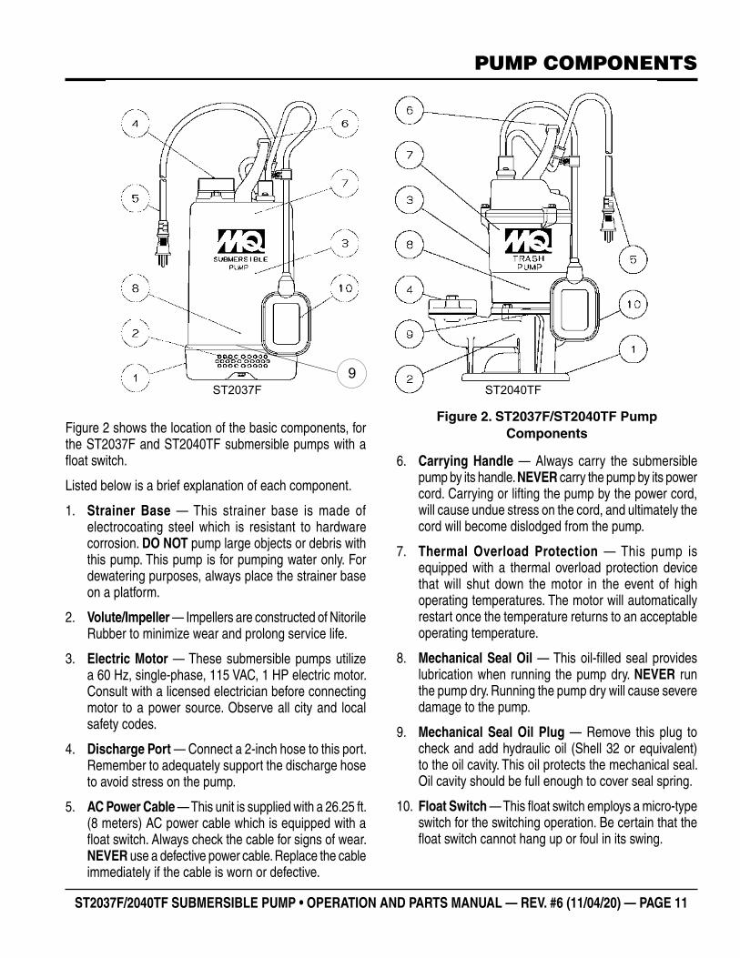
Figure 2. ST2037F/ST2040TF Pump ComponentsFigure 2 shows the location of the basic components, for
the ST2037F and ST2040TF submersible pumps with a float switch.
Listed below is a brief explanation of each component.
1. Strainer Base — This strainer base is made of electrocoating steel which is resistant to hardware corrosion. DO NOT pump large objects or debris with this pump. This pump is for pumping water only. For dewatering purposes, always place the strainer base on a platform.
2. Volute/Impeller — Impellers are constructed of Nitorile Rubber to minimize wear and prolong service life.
3. Electric Motor — These submersible pumps utilize a 60 Hz, single-phase, 115 VAC, 1 HP electric motor. Consult with a licensed electrician before connecting motor to a power source. Observe all city and local safety codes.
4. Discharge Port — Connect a 2-inch hose to this port. Remember to adequately support the discharge hose to avoid stress on the pump.
5. AC Power Cable — This unit is supplied with a 26.25 ft. (8 meters) AC power cable which is equipped with a float switch. Always check the cable for signs of wear. NEVER use a defective power cable. Replace the cable immediately if the cable is worn or defective.
6. Carrying Handle — Always carry the submersible pump by its handle. NEVER carry the pump by its power cord. Carrying or lifting the pump by the power cord, will cause undue stress on the cord, and ultimately the cord will become dislodged from the pump.
7. Thermal Overload Protection — This pump is equipped with a thermal overload protection device that will shut down the motor in the event of high operating temperatures. The motor will automatically restart once the temperature returns to an acceptable operating temperature.
8. Mechanical Seal Oil — This oil-filled seal provides lubrication when running the pump dry. NEVER run the pump dry. Running the pump dry will cause severe damage to the pump.
9. Mechanical Seal Oil Plug — Remove this plug to check and add hydraulic oil (Shell 32 or equivalent) to the oil cavity. This oil protects the mechanical seal. Oil cavity should be full enough to cover seal spring.
10. Float Switch — This float switch employs a micro-type switch for the switching operation. Be certain that the float switch cannot hang up or foul in its swing.
ST2037F ST2040TF9

PAGE 12 — ST2037F/2040TF SUBMERSIBLE PUMP • OPERATION AND PARTS MANUAL — REV. #6 (11/04/20)
FLOAT SWITCHES
FLOAT SWITCH THEORY
The float switch allows the pump to start and stop automatically when a prefixed liquid (water) level has been reached. A multiple closure device makes it highly reliable. This is the most universally-used float switch in the world for the automation of pumps.
HOW IT WORKS
This float switch is an economical chamber design float-type, liquid level switch that uses a microswitch for switching operation. As the liquid level (water) rises or falls, the float changes its angle until the microswitch makes or breaks the pump. The maximum switch angle range is 90 degrees. See Figure 3 below.
Figure 3. Switch Angle Range
DESIGN FEATURES
The float switch employs a microswitch and a latching ball for the switching operation. The latching ball design provides excellent resistance to nuisance trips due to fluid turbulence. The case and cable are hermetically sealed via re-injection molding.
�Suitable for most liquid environments.
�Hermetically sealed.
� Thick-walled non-corrosive Polypropylene enclosure.
�Max depth level, 1bar (10.2 mAg)
�Micro switch mechanical life - 3,000,000 operations
45°
45°
90°
PUMPING RANGE
The pumping range of the pump is determined by the float switch tether cord. The length of the float switch tether code is set to 150 mm at the factory. Please set the tether length to within 150 mm to prevent an improper operation.
Refer to Figure 4 for the pumping range of the ST2037F and ST2040TF. The minimum submergence level should never be less than 6 inches (150 mm) for the ST2037F or 6.3 inches (160 mm) for the ST2040TF above the pump bottom.
Pumping ranges are based on non-turbulent conditions. Range may vary due to water temperature and cord shape.
Figure 4. Pumping Range (Float Switch)
MIN
. - 6
in(1
50 m
m)
MIN
. - 6
.3 in
(160
mm
)
0 - 6
in(0
- 15
0 m
m)
0 - 6
in(0
- 15
0 m
m)
PUMPOFF
PUMPOFF
PUMPON
PUMPON
MAX
. - 1
9.7
in(5
00 m
m)
MAX
. - 2
0.1
in(5
10 m
m)

ST2037F/2040TF SUBMERSIBLE PUMP • OPERATION AND PARTS MANUAL — REV. #6 (11/04/20) — PAGE 13
INSTALLATION
ADJUSTING FLOAT SWITCH
1. Determine the required cord tether length as shown in Figure 4.
2. Loose a screw, cord clamp and float cord band on the float switch
3. Shift the float cord band to the required cord tether length ,then tighten the screw, cord clamp and float cord band.
SINGLE-PHASE POWER INSTALLATION (INPUT)
1. All submersible pumps referred to in this manual require 115 VAC, 60 Hz., single-phase power for normal operation.
2. If you cannot determine what your pump's power requirements are, look at the vendor supplied identification name tag attached to the pump or contact Multiquip's Technical Support Department.
CAUTION
When Installing the float switch, keep enough space around the float switch to avoid an improper operation.
POWER CORD REQUIREMENTS
When routing the 115 VAC, 60 Hz., single phase power via a power cord , ALWAYS use the correct wire size. Refer to Table 3 to determine the correct wire size. Incorrect wire size can adversely affect the performance of the pump.
CAUTION
Applying incorrect power (voltage phasing) to the submersible pump can cause severe damage to the pump.
Make sure that the correct voltage and phase are transferred to the pump at all times.
Table 3. Cord Length and Wire SizeAMPS 50 FT 100 FT 150 FT
6 16 AWG 16 AWG 14 AWG8 16 AWG 14 AWG 12 AWG
10 16 AWG 14 AWG 12 AWG12 14 AWG 14 AWG 12 AWG14 14 AWG 12 AWG 10 AWG16 12 AWG 12 AWG 10 AWG
Figure 5. Application Diagram
LIFTING
ROPE
SUBMERSIBLE
PUMP
CARRYING
HANDLE
2-INCH
DISCHARGE
HOSE
PUMP
ON
PUMP
OFF
FLOAT SWITCH
GFCI
RECEPTACLE
EXTERNAL
SINGLE PHASE
115 VAC
POWER SOURCE
POWER
CORD
PUMP
POWER
PLUG
PUMPING
RANGE
WATER
LEVEL

PAGE 14 — ST2037F/2040TF SUBMERSIBLE PUMP • OPERATION AND PARTS MANUAL — REV. #6 (11/04/20)
HOSE CONNECTIONS
1. 1. Connect a 2-inch hose to the discharge port on the pump as shown in Figure 6. Make sure that the hose is attached correctly to the discharge port.
ATTACHING LIFTING ROPE
1. Attach a suitable lifting cable (rope) to the carrying handle (Figure 6) on the pump and lower the pump into place. For applications where there is an excessive amount of mud, grit or silt, the use of a support platform is desirable. When pumping water from applications where there is little or no debris, the support platform is not required.
Figure 6. Submersible Pump Upright Position (Correct)
2. Make sure the pump is always placed in an upright position, not tilted (Figure 7). Never position the pump directly on a soft, loose bottom. Remember to attain maximum pumping capacity and prevent excessive wear, position the pump so it will not burrow itself into sand or clay.
SUPPORT
PLATFORM
CARRYING
HANDLE
LIFTING
ROPE
SUBMERSIBLE
PUMP
POWER
CORD
FLOAT
SWITCH
2-INCH
DISCHARGE
HOSE
OPERATION
Figure 7. Submersible Pump Upright Position (Incorrect)
3. If all of the pump’s electrical requirements have been met, place the circuit breaker or power ON/OFF switch in the ON position.
4. Wait a few seconds and water should begin to flow from the discharge hose.
5. If water is not flowing from the discharge hose or not flowing freely after a few minutes, remove the power from the pump and check the system for leaks.
6. To stop the pump from pumping, place the circuit breaker or ON/OFF switch in the OFF position.
SUBMERSIBLE
PUMP
DANGER
NEVER grab or touch a live power cord. DO NOT stand in water when connecting the pump’s power cord into a voltage source. The possibility exists of electrical shock, electrocution and possibly death!
ST2037F/2040TF SUBMERSIBLE PUMP • OPERATION AND PARTS MANUAL — REV. #6 (11/04/20) — PAGE 15
MAINTENANCE
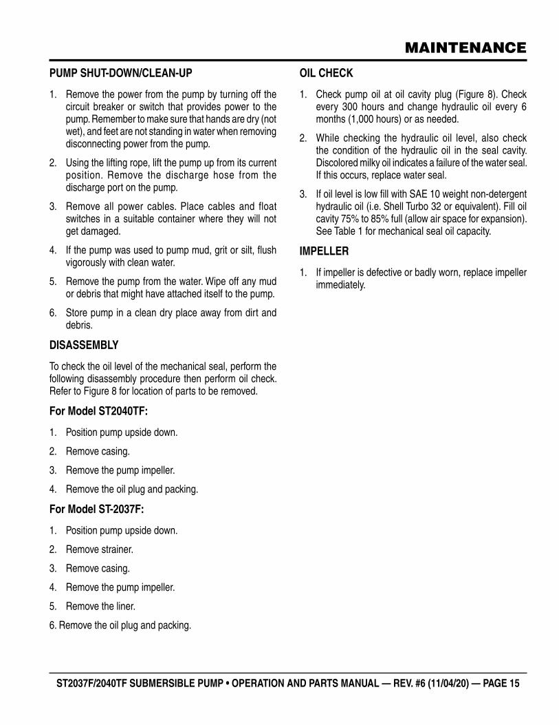
PUMP SHUT-DOWN/CLEAN-UP
1. Remove the power from the pump by turning off the circuit breaker or switch that provides power to the pump. Remember to make sure that hands are dry (not wet), and feet are not standing in water when removing disconnecting power from the pump.
2. Using the lifting rope, lift the pump up from its current position. Remove the discharge hose from the discharge port on the pump.
3. Remove all power cables. Place cables and float switches in a suitable container where they will not get damaged.
4. If the pump was used to pump mud, grit or silt, flush vigorously with clean water.
5. Remove the pump from the water. Wipe off any mud or debris that might have attached itself to the pump.
6. Store pump in a clean dry place away from dirt and debris.
DISASSEMBLY
To check the oil level of the mechanical seal, perform the following disassembly procedure then perform oil check. Refer to Figure 8 for location of parts to be removed.
For Model ST2040TF:
1. Position pump upside down.
2. Remove casing.
3. Remove the pump impeller.
4. Remove the oil plug and packing.
For Model ST-2037F:
1. Position pump upside down.
2. Remove strainer.
3. Remove casing.
4. Remove the pump impeller.
5. Remove the liner.
6. Remove the oil plug and packing.
OIL CHECK
1. Check pump oil at oil cavity plug (Figure 8). Check every 300 hours and change hydraulic oil every 6 months (1,000 hours) or as needed.
2. While checking the hydraulic oil level, also check the condition of the hydraulic oil in the seal cavity. Discolored milky oil indicates a failure of the water seal. If this occurs, replace water seal.
3. If oil level is low fill with SAE 10 weight non-detergent hydraulic oil (i.e. Shell Turbo 32 or equivalent). Fill oil cavity 75% to 85% full (allow air space for expansion). See Table 1 for mechanical seal oil capacity.
IMPELLER
1. If impeller is defective or badly worn, replace impeller immediately.

PAGE 16 — ST2037F/2040TF SUBMERSIBLE PUMP • OPERATION AND PARTS MANUAL — REV. #6 (11/04/20)
MAINTENANCE
Figure 8. Checking Hydraulic Oil

ST2037F/2040TF SUBMERSIBLE PUMP • OPERATION AND PARTS MANUAL — REV. #6 (11/04/20) — PAGE 17
TROUBLESHOOTING
Troubleshooting (Pump)Symptom Possible Problem Solution
Pump Fails To Start
Incorrect voltage/amps?
Check that proper voltage (115VAC, 60 Hz, single-phase) is being supplied to the pump. Also check that there is an adequate amount of current (amps) to run the pump. Check power source circuit breaker.
Malfunction in fl oat switch?Check that the movement of the fl oat switch is not obstructed. Inspect fl oat switch and power cord.
Blown power fuse? Replace fuse. Check cause of blown fuse.
Impeller locked?Disconnect power cord and check for clogging. Unclog pump. Check overload protection device.
Wet motor windings?
Use multimeter to check motor insulation. Insulation resistance must be greater than 15 megaohms. If resistance is low, disassemble pump motor and bake windings to dry them.
Defective motor and pump bearings? Check for excessive bearing wear. If worn, replace bearings. Replace motor if defective.
Pump Fails to Deliver Full Output
Twisted or restricted discharge hose? Lay hose fl at unkinked. Remove clog from hose line.
Clogged pump strainer? Clean strainer.
Low voltage?
Use a voltmeter to check voltage while pump is energized. Voltage must be within ±10%. Check power source (no load and load). If an extension cord is used, make sure it has adequate current-carrying capacity for the required length.
Impeller worn? Replace impeller.
Water in Seal OilDefective water seal? Replace water seal.Loose Oil Fill Plug? Tighten securely.
Pump Fails to Stop Malfunction in Float Switch? Check that the movement of the fl oat switch is not obstructed.

PAGE 18 — ST2037F/2040TF SUBMERSIBLE PUMP • OPERATION AND PARTS MANUAL — REV. #6 (11/04/20)
PERFORMANCE CURVE/ WIRING DIAGRAM
WIRING DIAGRAM
PERFORMANCE CURVES
115 VAC, 60Hz, ELECTRIC MOTOR
ST2037F
Tota
l Hea
d (ft
)To
tal H
ead
(ft)
ST2040TF
TOTAL HEADMax 37 ft
CAPACITYMax 73 G.P.M.
TOTAL HEADMax 40 ft
CAPACITYMax 79 G.P.M.
Quantity (G.P.M.)
Quantity (G.P.M.)

ST2037F/2040TF SUBMERSIBLE PUMP • OPERATION AND PARTS MANUAL — REV. #6 (11/04/20) — PAGE 19
NOTES

PAGE 20 — ST2037F/2040TF SUBMERSIBLE PUMP • OPERATION AND PARTS MANUAL — REV. #6 (11/04/20)
EXPLANATION OF CODE IN REMARKS COLUMN
The following section explains the different symbols and remarks used in the Parts section of this manual. Use the help numbers found on the back page of the manual if there are any questions.
SAMPLE PARTS LIST
NO. PART NO. PART NAME QTY. REMARKS1 12345 BOLT .....................1 .....INCLUDES ITEMS W/%2% WASHER, 1/4 IN. ..........NOT SOLD SEPARATELY2% 12347 WASHER, 3/8 IN. ..1 .....MQ-45T ONLY3 12348 HOSE ..................A/R ...MAKE LOCALLY4 12349 BEARING ..............1 .....S/N 2345B AND ABOVE
NO. Column
Unique Symbols — All items with same unique symbol (@, #, +, %, or >) in the number column belong to the same assembly or kit, which is indicated by a note in the “Remarks” column.
Duplicate Item Numbers — Duplicate numbers indicate multiple part numbers, which are in effect for the same general item, such as different size saw blade guards in use or a part that has been updated on newer versions of the same machine.
PART NO. Column
Numbers Used — Part numbers can be indicated by a number, a blank entry, or TBD.
TBD (To Be Determined) is generally used to show a part that has not been assigned a formal part number at the time of publication.
A blank entry generally indicates that the item is not sold separately or is not sold by Multiquip. Other entries will be clarifi ed in the “Remarks” Column.
NOTICE
The contents and part numbers listed in the parts section are subject to change without notice. Multiquip does not guarantee the availability of the parts listed.
NOTICE
When ordering a part that has more than one item number listed, check the remarks column for help in determining the proper part to order.
QTY. Column
Numbers Used — Item quantity can be indicated by a number, a blank entry, or A/R.
A/R (As Required) is generally used for hoses or other parts that are sold in bulk and cut to length.
A blank entry generally indicates that the item is not sold separately. Other entries will be clarifi ed in the “Remarks” Column.
REMARKS Column
Some of the most common notes found in the “Remarks” Column are listed below. Other additional notes needed to describe the item can also be shown.
Assembly/Kit — All items on the parts list with the same unique symbol will be included when this item is purchased.
Indicated by:“INCLUDES ITEMS W/(unique symbol)”
Serial Number Break — Used to list an effective serial number range where a particular part is used.
Indicated by: “S/N XXXXX AND BELOW”“S/N XXXX AND ABOVE”“S/N XXXX TO S/N XXX”
Specifi c Model Number Use — Indicates that the part is used only with the specifi c model number or model number variant listed. It can also be used to show a part is NOT used on a specifi c model or model number variant.
Indicated by:“XXXXX ONLY”“NOT USED ON XXXX”
“Make/Obtain Locally” — Indicates that the part can be purchased at any hardware shop or made out of available items. Examples include battery cables, shims, and certain washers and nuts.
“Not Sold Separately” — Indicates that an item cannot be purchased as a separate item and is either part of an assembly/kit that can be purchased, or is not available for sale through Multiquip.
ST2037F/2040TF SUBMERSIBLE PUMP • OPERATION AND PARTS MANUAL — REV. #6 (11/04/20) — PAGE 21
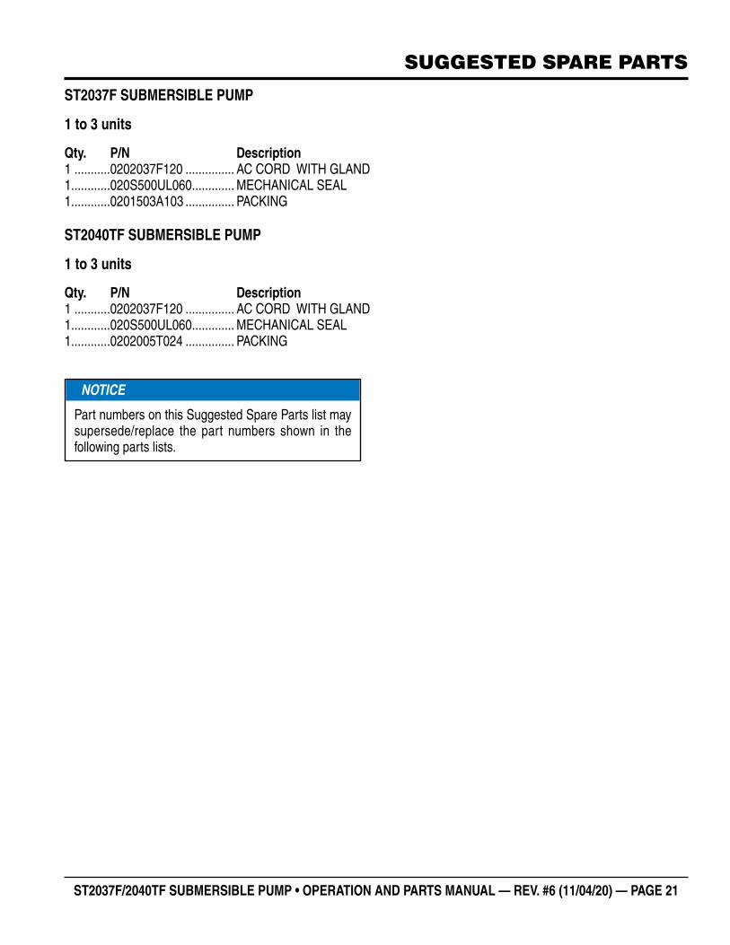
SUGGESTED SPARE PARTS
ST2037F SUBMERSIBLE PUMP
1 to 3 units
Qty. P/N Description1 ...........0202037F120 ............... AC CORD WITH GLAND1............020S500UL060 ............. MECHANICAL SEAL1............0201503A103 ............... PACKING
ST2040TF SUBMERSIBLE PUMP
1 to 3 units
Qty. P/N Description1 ...........0202037F120 ............... AC CORD WITH GLAND1............020S500UL060 ............. MECHANICAL SEAL1............0202005T024 ............... PACKING
NOTICE
Part numbers on this Suggested Spare Parts list may supersede/replace the part numbers shown in the following parts lists.

PAGE 22 — ST2037F/2040TF SUBMERSIBLE PUMP • OPERATION AND PARTS MANUAL — REV. #6 (11/04/20)
ST2037F PUMP ASSEMBLY
ST-2037F--ELECTRIC SUBMERSIBLE PUMP ASSY.
PAGE 19 — ST-2037F,ST-2040TF SUB. PUMPS — OPERATION & PARTS MANUAL — REV. #1 (05/25/15)
ST-2037F ELECTRIC SUBMERSIBLE PUMP ASSY.

ST2037F/2040TF SUBMERSIBLE PUMP • OPERATION AND PARTS MANUAL — REV. #6 (11/04/20) — PAGE 23
NO. PART NO. PART NAME QTY. REMARKS1 020S500UL001 CASING 13 020S500UL003 IMPELLER 14 020S500UL004 IMPELLER NUT 15 020S500UL005 SPRING WASHER 17 020S500UL007 CASING COVER 134 020S2037034 SCREW 353 020S500UL053 WASHER 160 020S500UL060 MECHANICAL SEAL 165 020S500UL065 PLUG 167 020S500UL067 PACKING 174 020S500UL074 PACKING 1102 0202005A102 DISCHARGE PORT 1103 0201503A103 PACKING 1119 020S2047119 MOTOR ..................................................................1............INCLUDES ITEMS W/ $120 0202037F120 AC CORD W/CORD GLAND .................................1............W/ FLOAT SWITCH121 0201503A121 CORD CLAMP .......................................................1............REPLACES P/N 0201503121121-1 0202037F1211 CORD CLAMP 1123 0202037F123 CHAIN 1125 0201503A125 SCREW ..................................................................2............REPLACES P/N 0201503125127 0202037F127 CARRYING HANDLE 1129 020S2047129 FRAME COVER 1131 020S2047131 BOLT 3145 0202037F145 SET PIECE 1146 020S500UL146 STRAINER 1157$ 020S2047157 PACKING 1170 020S500UL170 IMPELLER NUT CAP 1174 020S2037174 OUTER PIPE 1214 020S500UL214 PACKING 1224 0201503A224 PLUG .....................................................................1............REPLACES P/N 0201503224236 0202037F236 S-TIP 1238 020S500UL238 SPACER 3265 011008020 BOLT ......................................................................2............REPLACES P/N 020S500UL265299 020S500UL299 BOLT 3300 020S500UL300 WASHER 3358 020S500UL358 AC CORD BAND 1358-1 020S500UL358 FLOAT CORD BAND 1431 020S500UL431 NUT 2444 020S500UL444 SCREW 1444-1 0202037F4441 SCREW ..................................................................1............INCLUDES ITEMS W/ #445$ 020S2047445 CAPACITOR 1446$ 020S2047446 THERMAL PROTECTOR 1829 020S500UL829 WASHER 2830# NUT 1830-1# NUT 1893 020S500UL893 SEAT 1894 020S500UL894 V-RING 1895 020S500UL895 LINER 1896 020S500UL896 SCREW 3918 020S500UL918 STIRRER 1
ST2037F PUMP ASSEMBLY

PAGE 24 — ST2037F/2040TF SUBMERSIBLE PUMP • OPERATION AND PARTS MANUAL — REV. #6 (11/04/20)
ST2040TF PUMP ASSEMBLY
ST-2040TF--ELECTRIC SUBMERSIBLE PUMP ASSY.
PAGE 21 — ST-2037F,ST-2040TF SUB. PUMPS — OPERATION & PARTS MANUAL — REV. #1(05/25/15)
ST-2040TF ELECTRIC SUBMERSIBLE PUMP ASSY.

ST2037F/2040TF SUBMERSIBLE PUMP • OPERATION AND PARTS MANUAL — REV. #6 (11/04/20) — PAGE 25
NO. PART NO. PART NAME QTY. REMARKS1 020S2040T001 CASING 13 020S500UL003 IMPELLER, NITRILE RUBBER 14 020S500UL004 IMPELLER NUT 15 020S500UL005 SPRING WASHER 17 020S2040T007 CASING COVER 18 0202005T008 CASING PACKING 123 020S2040T023 COMPANION FLANGE 124 0202005T024 PACKING 134 020S2037034 SCREW 342 020S2040T042 BOLT 253 020S500UL053 WASHER 160 020S500UL060 MECHANICAL SEAL 165 020S2040T065 PLUG 174 020S500UL074 PACKING 176 020S2040T076 BOLT 3119 020S2047119 MOTOR ..................................................................1............INCLUDES ITEMS W/ $120 0202037F120 AC CORD W/ CORD GLAND ................................1............W/ FLOAT SWITCH121 0201503A121 CORD CLAMP .......................................................1............REPLACES P/N 0201503121121-1 0202037F1211 CORD CLAMP 1123 0202037F123 CHAIN 1125 0201503A125 SCREW ..................................................................2............REPLACES P/N 0201503125127 020S500UL127 CARRYING HANDLE 1129 020S2047129 FRAME COVER 1131 020S2047131 BOLT 3145 020237F145 SET PIECE 1157$ 020S2047157 PACKING 1170 020S500UL170 IMPELLER NUT CAP 1224 0201503A224 PLUG .....................................................................1............REPLACES P/N 0201503224236 02037F236 S-TIP 1265 020S2040T265 BOLT 2358 020S500UL358 AC CORD BAND 1358-1 020S500UL358 FLOAT CORD BAND 1444 020S500UL444 SCREW 1444-1 0202037F4441 SCREW ..................................................................1............INCLUDES ITEMS W/ #445$ 020S2047445 CAPACITOR 1446$ 020S2047446 THERMAL PROTECTOR 1530 0202005T530 BOTTOM PLATE 1531 011106015 BOLT ......................................................................3............REPLACES P/N 0202005T531829 020S500UL829 WASHER 2830# 0202037F441 NUT 1830-1# 0202037F441 NUT 1893 020S2040T893 SEAT WITH PACKING 1894 020S500UL894 V-RING 1918 020S500UL918 STIRRER 1
ST2040TF PUMP ASSEMBLY

OPERATION AND PARTS MANUAL
Your Local Dealer is:
HERE’S HOW TO GET HELPPLEASE HAVE THE MODEL AND SERIAL
NUMBER ON-HAND WHEN CALLING
© COPYRIGHT 2020, MULTIQUIP INC.
Multiquip Inc , the MQ logo are registered trademarks of Multiquip Inc. and may not be used, reproduced, or altered without written permission. All other trademarks are the property of their respective owners and used with permission.
This manual MUST accompany the equipment at all times. This manual is considered a permanent part of the equipment and should remain with the unit if resold.
The information and specifi cations included in this publication were in effect at the time of approval for printing. Illustrations, descriptions, references and technical data contained in this manual are for guidance only and may not be considered as binding. Multiquip Inc. reserves the right to discontinue or change specifi cations, design or the information published in this publication at any time without notice and without incurring any obligations.
UNITED STATES Multiquip Inc.
(310) 537- 3700 6141 Katella Avenue Suite 200Cypress, CA 90630 E-MAIL: [email protected]: www.multiquip.com
CANADA UNITED KINGDOM
Multiquip Multiquip (UK) Limited Head Offi ce
(450) 625-2244 4110 Industriel Boul.Laval, Quebec, Canada H7L 6V3 E-MAIL : [email protected]
0161 339 2223 Unit 2, Northpoint Industrial Estate, Globe Lane,Dukinfi eld, Cheshire SK16 4UJ E-MAIL : [email protected]