models wpsb series ii - dunkirk rev f wpsb iom.pdfwpsb-6d wpsb-6dp wpsb-7d wpsb-7dp wpsb-8d wpsb-8dp...
TRANSCRIPT
GAS-FIRED HOT WATER BOILERS
INSTALLATION, OPERATION & MAINTENANCE MANUAL
P/N 240009047, Rev. F [05/17/2017]
WPSB SERIES IIModels WPSB-3D
WPSB-3DPWPSB-4D
WPSB-4DPWPSB-5D
WPSB-5DPWPSB-6D
WPSB-6DPWPSB-7D
WPSB-7DPWPSB-8D
WPSB-8DPWPSB-9D
WPSB-9DP
Manufactured by:ECR International, Inc.
2201 Dwyer Avenue, Utica NY 13501web site: www.ecrinternational.com
Tested For 50 psi.ASME
Working Pressure
2 P/N 240009047, Rev. F [05/17/2017]
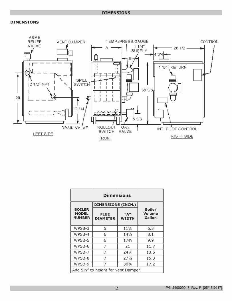
DIMENSIONS
Dimensions
BOILER MODEL
NUMBER
DIMENSIONS (INCH.)Boiler
Volume Gallon
FLUE DIAMETER
“A” WIDTH
WPSB-3 5 11¼ 6.3WPSB-4 6 14½ 8.1WPSB-5 6 17¾ 9.9WPSB-6 7 21 11.7WPSB-7 7 24¼ 13.5WPSB-8 7 27½ 15.3WPSB-9 7 30¾ 17.2
Add 5½” to height for vent Damper.
DIMENSIONS
CONTROL
3 P/N 240009047, Rev. F [05/17/2017]
BOILER RATINGS AND CAPACITIES
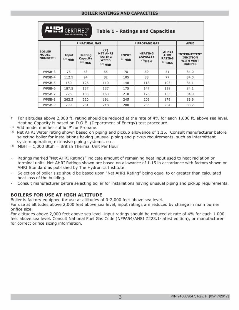
Table 1 - Ratings and Capacities
BOILER MODEL NUMBER (1)
† NATURAL GAS † PROPANE GAS AFUE
Input (3) Mbh
Heating Capacity (3) Mbh
(2) NET AHRIRATING Water, (3) Mbh
INPUT (3)Mbh
HEATING CAPACITY
(3)MBH
(2) NET AHRI
RATING (3) Mbh
INTERMITTENT IGNITION
WITH VENT DAMPER
WPSB-3 75 63 55 70 59 51 84.0
WPSB-4 112.5 94 82 105 88 77 84.0
WPSB-5 150 126 110 140 118 103 84.1
WPSB-6 187.5 157 137 175 147 128 84.1
WPSB-7 225 188 163 210 176 153 84.0
WPSB-8 262.5 220 191 245 206 179 83.9
WPSB-9 299 251 218 280 235 204 83.7
† For altitudes above 2,000 ft. rating should be reduced at the rate of 4% for each 1,000 ft. above sea level. Heating Capacity is based on D.O.E. (Department of Energy) test procedure.(1) Add model number suffix ‘P’ for Propane.(2) Net AHRI Water rating shown based on piping and pickup allowance of 1.15. Consult manufacturer before
selecting boiler for installations having unusual piping and pickup requirements, such as intermittent system operation, extensive piping systems, etc.
(3) MBH = 1,000 Btuh = British Thermal Unit Per Hour
- Ratings marked “Net AHRI Ratings” indicate amount of remaining heat input used to heat radiation or terminal units. Net AHRI Ratings shown are based on allowance of 1.15 in accordance with factors shown on AHRI Standard as published by The Hydronics Institute.
- Selection of boiler size should be based upon “Net AHRI Rating” being equal to or greater than calculated heat loss of the building.
- Consult manufacturer before selecting boiler for installations having unusual piping and pickup requirements.
BOILERS FOR USE AT HIGH ALTITUDEBoiler is factory equipped for use at altitudes of 0-2,000 feet above sea level. For use at altitudes above 2,000 feet above sea level, input ratings are reduced by change in main burner orifice size.For altitudes above 2,000 feet above sea level, input ratings should be reduced at rate of 4% for each 1,000 feet above sea level. Consult National Fuel Gas Code (NFPA54/ANSI Z223.1-latest edition), or manufacturer for correct orifice sizing information.
4
TABLE OF CONTENTS
IMPORTANT: Read the following instructions COMPLETELY before installing!!
KEEP THIS MANUAL NEAR BOILERRETAIN FOR FUTURE REFERENCE
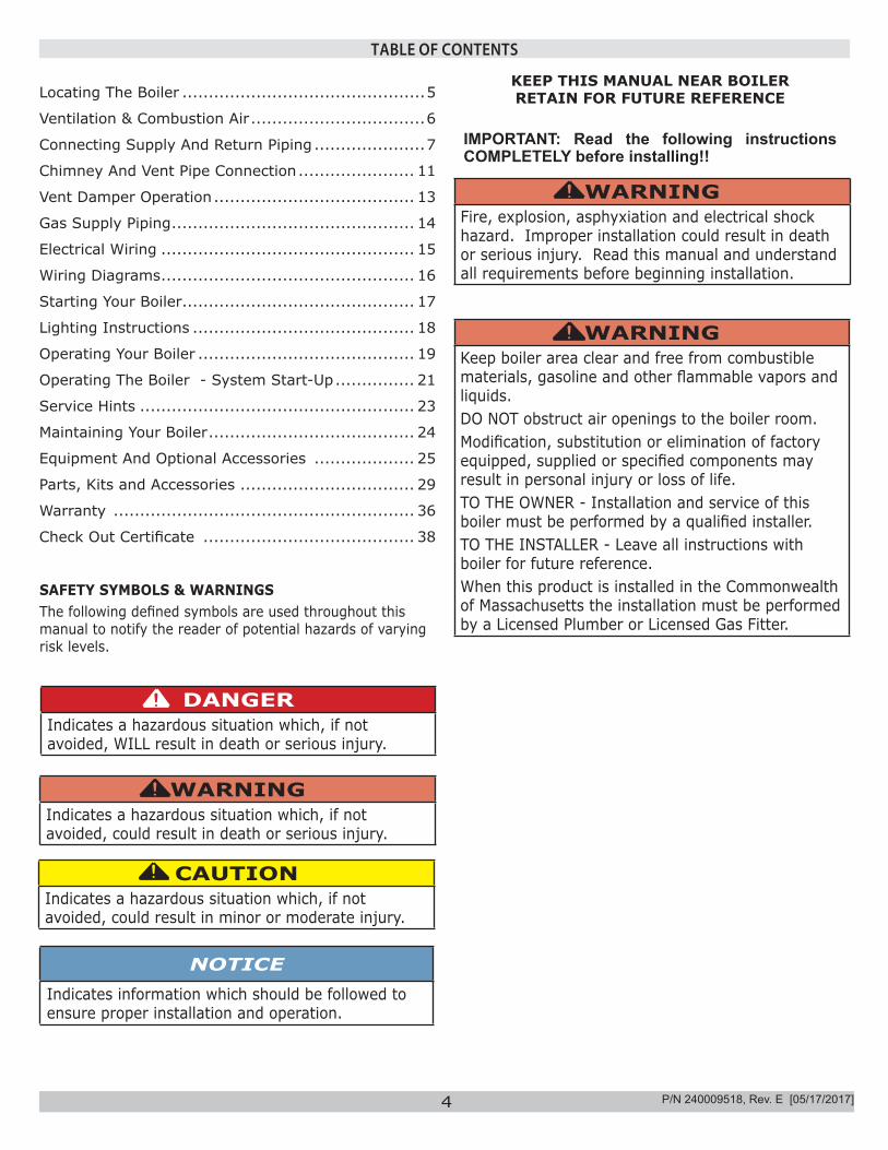
SAFETY SYMBOLS & WARNINGSThe following defined symbols are used throughout this manual to notify the reader of potential hazards of varying risk levels.
DANGERIndicates a hazardous situation which, if not avoided, WILL result in death or serious injury.
!
WARNINGIndicates a hazardous situation which, if not avoided, could result in death or serious injury.
!
CAUTIONIndicates a hazardous situation which, if not avoided, could result in minor or moderate injury.
!
NOTICEIndicates information which should be followed to ensure proper installation and operation.
WARNINGFire, explosion, asphyxiation and electrical shock hazard. Improper installation could result in death or serious injury. Read this manual and understand all requirements before beginning installation.
!
WARNINGKeep boiler area clear and free from combustible materials, gasoline and other flammable vapors and liquids.DO NOT obstruct air openings to the boiler room.Modification, substitution or elimination of factory equipped, supplied or specified components may result in personal injury or loss of life.TO THE OWNER - Installation and service of this boiler must be performed by a qualified installer.TO THE INSTALLER - Leave all instructions with boiler for future reference.When this product is installed in the Commonwealth of Massachusetts the installation must be performed by a Licensed Plumber or Licensed Gas Fitter.
!
P/N 240009518, Rev. E [05/17/2017]
Locating The Boiler ..............................................5
Ventilation & Combustion Air .................................6
Connecting Supply And Return Piping .....................7
Chimney And Vent Pipe Connection ...................... 11
Vent Damper Operation ...................................... 13
Gas Supply Piping .............................................. 14
Electrical Wiring ................................................ 15
Wiring Diagrams ................................................ 16
Starting Your Boiler ............................................ 17
Lighting Instructions .......................................... 18
Operating Your Boiler ......................................... 19
Operating The Boiler - System Start-Up ............... 21
Service Hints .................................................... 23
Maintaining Your Boiler ....................................... 24
Equipment And Optional Accessories ................... 25
Parts, Kits and Accessories ................................. 29
Warranty ......................................................... 36
Check Out Certificate ........................................ 38
5
LOCATING THE BOILER
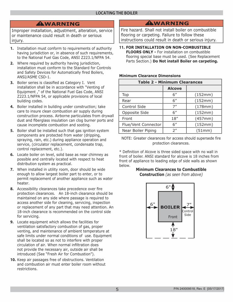
Minimum Clearance DimensionsTable 2 - Minimum Clearances
AlcoveTop 6” (152mm)Rear 6” (152mm)Control Side 7” (178mm)Opposite Side 6” (152mm)Front 18” (457mm)Flue/Vent Connector 6” (152mm)Near Boiler Piping 2” (51mm)
1. Installation must conform to requirements of authority having jurisdiction or, in absence of such requirements, to the National Fuel Gas Code, ANSI Z223.1/NFPA 54.
2. Where required by authority having jurisdiction, installation must conform to the Standard for Controls and Safety Devices for Automatically fired Boilers, ANSI/ASME CSD-1.
3. Boiler series is classified as Category I. Vent installation shall be in accordance with "Venting of Equipment ," of the National Fuel Gas Code, ANSI Z223.1/NFPA 54, or applicable provisions of local building codes.
4. Boiler installed in building under construction; take care to insure clean combustion air supply during construction process. Airborne particulates from drywall dust and fiberglass insulation can clog burner ports and cause incomplete combustion and sooting.
5. Boiler shall be installed such that gas ignition system components are protected from water (dripping, spraying, rain, etc.) during appliance operation and service, (circulator replacement, condensate trap, control replacement, etc.).
6. Locate boiler on level, solid base as near chimney as possible and centrally located with respect to heat distribution system as practical.
7. When installed in utility room, door should be wide enough to allow largest boiler part to enter, or to permit replacement of another appliance such as water heater.
8. Accessibility clearances take precedence over fire protection clearances. An 18-inch clearance should be maintained on any side where passage is required to access another side for cleaning, servicing, inspection or replacement of any part that may need attention. An 18-inch clearance is recommended on the control side for servicing.
9. Locate equipment which allows the facilities for ventilation satisfactory combustion of gas, proper venting, and maintenance of ambient temperature at safe limits under normal conditions of use. Equipment shall be located so as not to interfere with proper circulation of air. When normal infiltration does not provide the necessary air, outside air shall be introduced (See “Fresh Air for Combustion”).
10. Keep air passages free of obstructions. Ventilation and combustion air must enter boiler room without restrictions.
WARNINGFire hazard. Shall not install boiler on combustible flooring or carpeting. Failure to follow these instructions could result in death or serious injury.
!
11. FOR INSTALLATION ON NON-COMBUSTIBLE FLOORS ONLY - For installation on combustible flooring special base must be used. (See Replacement Parts Section.) Do Not install Boiler on carpeting.
NOTE: Greater clearances for access should supersede fire protection clearances.
* Definition of Alcove is three sided space with no wall in front of boiler. ANSI standard for alcove is 18 inches from front of appliance to leading edge of side walls as shown below.
Minimum Clearances to Combustible Construction (as seen from above)
7"
6"
BOILER
18"
6"
FrontControl
Side
WARNINGImproper installation, adjustment, alteration, service or maintenance could result in death or serious injury.
!
P/N 240009518, Rev. E [05/17/2017]
6
VENTILATION & COMBUSTION AIR
Provide combustion air and ventilation air in accordance with the section “Air for Combustion and Ventilation,” of the National Fuel Gas Code, ANSI Z223.1 / NFPA 54, or applicable provisions of local building codes. Provide make-up air where exhaust fans, clothes dryers, and kitchen ventilation equipment interfere with proper operation.National Fuel Gas Code recognizes several methods of obtaining adequate ventilation and combustion air. Requirements of the authority having jurisdiction may override these methods.
• Engineered Installations. Must be approved by authority having jurisdiction.
• Mechanical Air Supply. Provide minimum of 0.35 cfm per Mbh for all appliances located within space. Additional requirements where exhaust fans installed. Interlock each appliance to mechanical air supply system to prevent main burner operation when mechanical air supply system not operating.
• All Indoor Air. Calculate minimum volume for all appliances in space. Use a different method if minimum volume not available.
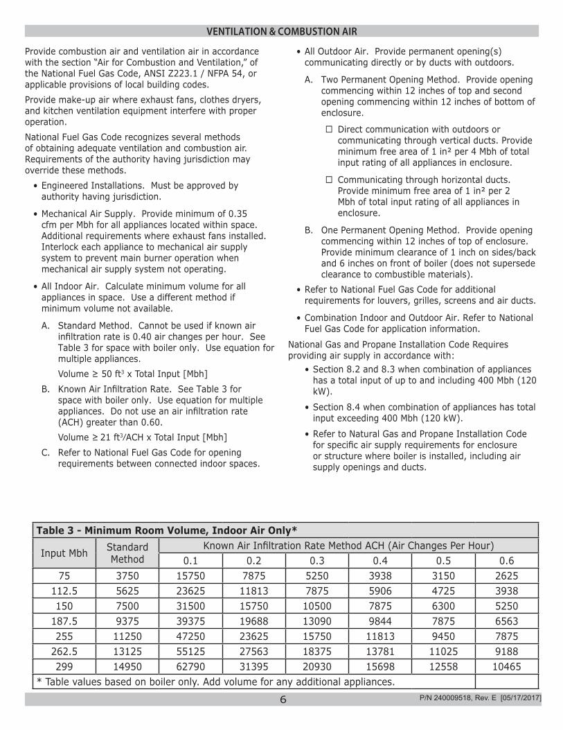
A. Standard Method. Cannot be used if known air infiltration rate is 0.40 air changes per hour. See Table 3 for space with boiler only. Use equation for multiple appliances.Volume ≥ 50 ft3 x Total Input [Mbh]
B. Known Air Infiltration Rate. See Table 3 for space with boiler only. Use equation for multiple appliances. Do not use an air infiltration rate (ACH) greater than 0.60.Volume ≥ 21 ft3⁄ACH x Total Input [Mbh]
C. Refer to National Fuel Gas Code for opening requirements between connected indoor spaces.
• All Outdoor Air. Provide permanent opening(s) communicating directly or by ducts with outdoors.
A. Two Permanent Opening Method. Provide opening commencing within 12 inches of top and second opening commencing within 12 inches of bottom of enclosure.
� Direct communication with outdoors or communicating through vertical ducts. Provide minimum free area of 1 in² per 4 Mbh of total input rating of all appliances in enclosure.
� Communicating through horizontal ducts. Provide minimum free area of 1 in² per 2 Mbh of total input rating of all appliances in enclosure.
B. One Permanent Opening Method. Provide opening commencing within 12 inches of top of enclosure. Provide minimum clearance of 1 inch on sides/back and 6 inches on front of boiler (does not supersede clearance to combustible materials).
• Refer to National Fuel Gas Code for additional requirements for louvers, grilles, screens and air ducts.
• Combination Indoor and Outdoor Air. Refer to National Fuel Gas Code for application information.
National Gas and Propane Installation Code Requires providing air supply in accordance with:
• Section 8.2 and 8.3 when combination of appliances has a total input of up to and including 400 Mbh (120 kW).
• Section 8.4 when combination of appliances has total input exceeding 400 Mbh (120 kW).
• Refer to Natural Gas and Propane Installation Code for specific air supply requirements for enclosure or structure where boiler is installed, including air supply openings and ducts.
Table 3 - Minimum Room Volume, Indoor Air Only*
Input Mbh Standard Method
Known Air Infiltration Rate Method ACH (Air Changes Per Hour)0.1 0.2 0.3 0.4 0.5 0.6
75 3750 15750 7875 5250 3938 3150 2625112.5 5625 23625 11813 7875 5906 4725 3938150 7500 31500 15750 10500 7875 6300 5250
187.5 9375 39375 19688 13090 9844 7875 6563255 11250 47250 23625 15750 11813 9450 7875
262.5 13125 55125 27563 18375 13781 11025 9188299 14950 62790 31395 20930 15698 12558 10465
* Table values based on boiler only. Add volume for any additional appliances. P/N 240009518, Rev. E [05/17/2017]
7
CONNECTING SUPPLY AND RETURN PIPING
RELIEF VALVE
DISCHARGE LINE
Check local codes for maximum distance
from floor or allowable safe point of discharge.
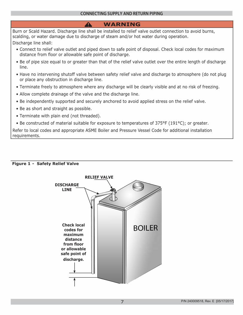
WARNINGBurn or Scald Hazard. Discharge line shall be installed to relief valve outlet connection to avoid burns, scalding, or water damage due to discharge of steam and/or hot water during operation.Discharge line shall:
• Connect to relief valve outlet and piped down to safe point of disposal. Check local codes for maximum distance from floor or allowable safe point of discharge.
• Be of pipe size equal to or greater than that of the relief valve outlet over the entire length of discharge line.
• Have no intervening shutoff valve between safety relief valve and discharge to atmosphere (do not plug or place any obstruction in discharge line.
• Terminate freely to atmosphere where any discharge will be clearly visible and at no risk of freezing.• Allow complete drainage of the valve and the discharge line.• Be independently supported and securely anchored to avoid applied stress on the relief valve.• Be as short and straight as possible.• Terminate with plain end (not threaded).• Be constructed of material suitable for exposure to temperatures of 375°F (191°C); or greater.
Refer to local codes and appropriate ASME Boiler and Pressure Vessel Code for additional installation requirements.
!
Figure 1 - Safety Relief Valve
P/N 240009518, Rev. E [05/17/2017]
8
CONNECTING SUPPLY AND RETURN PIPING
WARNINGBurn and scald hazard. Safety relief valve could discharge steam or hot water during operation. Install discharge piping per these instructions.
!
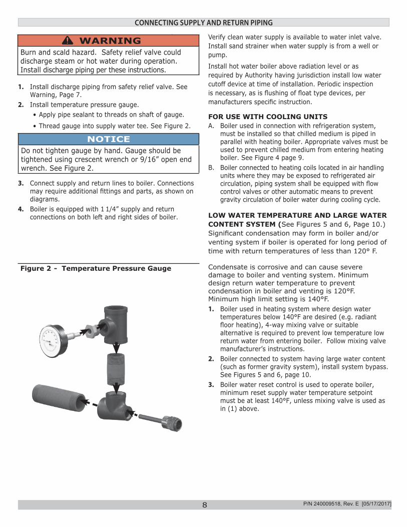
Figure 2 - Temperature Pressure Gauge
1. Install discharge piping from safety relief valve. See Warning, Page 7.
2. Install temperature pressure gauge.• Apply pipe sealant to threads on shaft of gauge.
• Thread gauge into supply water tee. See Figure 2.
NOTICEDo not tighten gauge by hand. Gauge should be tightened using crescent wrench or 9/16” open end wrench. See Figure 2.
3. Connect supply and return lines to boiler. Connections may require additional fittings and parts, as shown on diagrams.
4. Boiler is equipped with 1 1/4” supply and return connections on both left and right sides of boiler.
Verify clean water supply is available to water inlet valve. Install sand strainer when water supply is from a well or pump.
Install hot water boiler above radiation level or as required by Authority having jurisdiction install low water cutoff device at time of installation. Periodic inspection is necessary, as is flushing of float type devices, per manufacturers specific instruction.
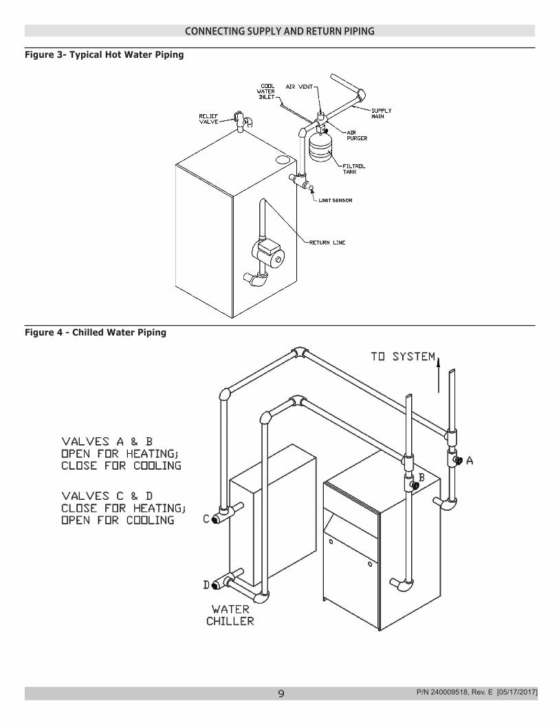
FOR USE WITH COOLING UNITSA. Boiler used in connection with refrigeration system,
must be installed so that chilled medium is piped in parallel with heating boiler. Appropriate valves must be used to prevent chilled medium from entering heating boiler. See Figure 4 page 9.
B. Boiler connected to heating coils located in air handling units where they may be exposed to refrigerated air circulation, piping system shall be equipped with flow control valves or other automatic means to prevent gravity circulation of boiler water during cooling cycle.
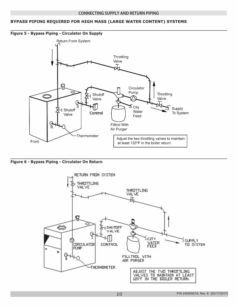
LOW WATER TEMPERATURE AND LARGE WATER CONTENT SYSTEM (See Figures 5 and 6, Page 10.)Significant condensation may form in boiler and/or venting system if boiler is operated for long period of time with return temperatures of less than 120° F.
Condensate is corrosive and can cause severe damage to boiler and venting system. Minimum design return water temperature to prevent condensation in boiler and venting is 120°F. Minimum high limit setting is 140°F.1. Boiler used in heating system where design water
temperatures below 140°F are desired (e.g. radiant floor heating), 4-way mixing valve or suitable alternative is required to prevent low temperature low return water from entering boiler. Follow mixing valve manufacturer’s instructions.
2. Boiler connected to system having large water content (such as former gravity system), install system bypass. See Figures 5 and 6, page 10.
3. Boiler water reset control is used to operate boiler, minimum reset supply water temperature setpoint must be at least 140°F, unless mixing valve is used as in (1) above.
P/N 240009518, Rev. E [05/17/2017]
9
Figure 4 - Chilled Water Piping
Figure 3- Typical Hot Water Piping
CONNECTING SUPPLY AND RETURN PIPING
P/N 240009518, Rev. E [05/17/2017]
10
Figure 5 - Bypass Piping - Circulator On Supply
BYPASS PIPING REQUIRED FOR HIGH MASS (LARGE WATER CONTENT) SYSTEMS
CONTROL
Control
CONNECTING SUPPLY AND RETURN PIPING
Figure 6 - Bypass Piping - Circulator On Return
P/N 240009518, Rev. E [05/17/2017]
11
Boilers connecting to gas vents or chimneys, vent installations shall be in accordance with “Venting of Equipment”, of the National Fuel Gas Code, ANSI Z223.1/NFPA 54, or applicable provisions of local building codes.
Check Your ChimneyIt must be clean, right size, properly constructed and in good condition.
Chimney SizingChimney sizing, and vent installation must be in accordance with the National Fuel Gas Code, ANSI Z223.1/NFPA 54, or applicable provisions of local building codes.
This is a high efficiency boiler with low stack temperature. Following recommendations are in addition to requirements of the National Fuel Gas Code.1. Type B double wall vent pipe is recommended for
vent connector. Single wall vent connectors should not be used unless following conditions are true:a) Except for basement, boiler is not installed in
unheated space.b) Total horizontal portion of vent connector, not
including elbows is less than 5 feet in length.2. Outside chimneys (i.e. chimneys exposed to
outdoors below roof line) should not be used unless they are:a) enclosed in a chase, orb) lined with type B vent pipe, or listed flexible vent liner, or other certified chimney lining system.
3. Where possible it is recommended to common vent boiler and water heater.
4. For multiple boiler installations, consult boiler manufacturer for venting recommendations.
Connecting The Vent Damper And Vent ConnectorRefer to Dimensions, page 2 for size and location of vent (flue opening).
NOTICEDamper blade on furnished vent damper has 1/2 square inch hole (approximately 3/4” diameter). Boilers equipped with intermittent ignition, hole should be plugged by using plug supplied with vent damper.
1. Position furnished vent damper on top of flue outlet collar. Fasten damper securely to flue outlet collar with sheet metal screws. Verify damper blade has clearance to operate inside of diverter. Do not modify either draft diverter or vent damper during installation.As An OptionDamper may be installed in a horizontal or vertical position, closer to flue outlet collar preferred. See Figures 7, 8 and 9, and Vent Damper Instructions.
2. Install vent damper to service only single boiler for which it is intended. Damper position indicator shall be in visible location following installation. Locate damper so it is accessible for servicing.
3. Damper must be in the open position when appliance main burners are operating.
4. Boiler is equipped with factory wired harness that plugs into vent damper.
5. Slope pipe up from boiler to chimney not less than 1/4” per foot.
6. Run pipe as directly as possible with as few elbows as possible.
7. Do not connect to fireplace flue.8. End of vent pipe must be flush with inside face of
chimney flue. Use a sealed-in thimble for chimney connection.
Sections of vent pipe should be fastened with sheet metal screws to make piping rigid. Horizontal potions of vent system must be supported to prevent sagging. Use stovepipe wires every 5’ to support pipe from above. If vent pipe must go through crawl space, double wall vent pipe should be used. Where vent pipe passes through combustible wall or partition, use ventilated metal thimble. Thimble should be 4 inches larger in diameter than vent pipe.Minimum Vent Pipe ClearanceWood and other combustible materials must not be closer than 6” from any surface of single wall metal vent pipe. Listed Type B vent pipe or other listed venting systems shall be installed in accordance with their listing.
CHIMNEY AND VENT PIPE CONNECTION
P/N 240009518, Rev. E [05/17/2017]
12
Removing Existing Boiler From Common Venting SystemWhen an existing boiler is removed from common venting system, common venting system is likely to be too large for proper venting of appliances remaining connected to it.At time of removal of existing boiler, following steps shall be followed with each appliance remaining connected to the common venting system placed in operation, while other appliances remaining connected to common venting system are not in operation.1. Seal any unused openings in the common venting
system.2. Visually inspect the venting system for proper size and
horizontal pitch and determine there is no blockage or restriction, leakage, corrosion and other deficiencies which could cause an unsafe condition.
3. Insofar as is practical, close all building doors and windows and all doors between the space in which the appliances remaining connected to the common venting system are located and other spaces of the building. Turn on clothes dryers and any appliance not connected to the common venting system. Turn on any exhaust fans, such as range hoods and bathroom exhausts, so they will operate at maximum speed. Do not operate a summer exhaust fan. Close fireplace dampers.
4. Place in operation the appliance being inspected. Follow the lighting instructions. Adjust thermostat so appliance will operate continuously.
5. Test for spillage at the draft hood relief opening after 5 minutes of main burner operation. Use the flame of a match or candle, or smoke from a cigarette, cigar or pipe.
6. After it has been determined that each appliance remaining connected to the common venting system properly vents when tested as outlined above, return doors, windows, exhaust fans, fireplace dampers and any other gas-burning appliance to their previous conditions of use.
CHIMNEY AND VENT PIPE CONNECTION
7. Any improper operation of the common venting system should be corrected so the installation conforms with the National Fuel Gas Code, ANSI Z223.1/NFPA 54. When re-sizing any portion of the common venting system, the common venting system should be re-sized to approach the minimum size as determined using the appropriate tables in Chapter 13 of the National Fuel Gas Code, ANSI Z223.1/NFPA 54.
Vent connectors serving appliances vented by natural draft shall not be connected into any portion of mechanical draft systems operating under positive pressure.
P/N 240009518, Rev. E [05/17/2017]
13
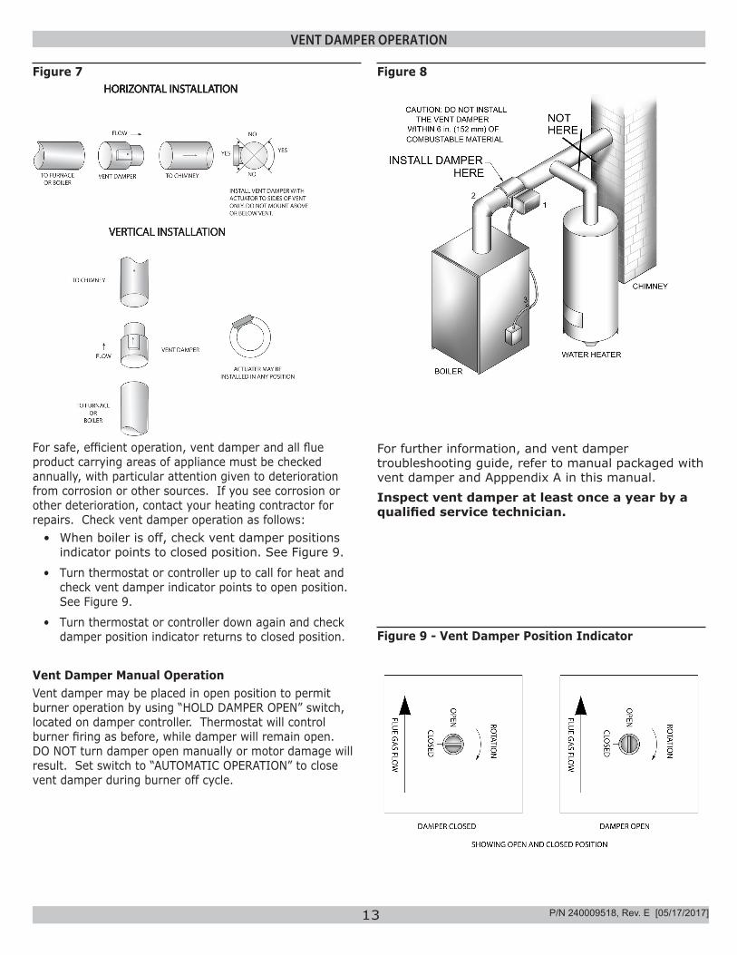
VENT DAMPER OPERATION
Figure 7 Figure 8
For safe, efficient operation, vent damper and all flue product carrying areas of appliance must be checked annually, with particular attention given to deterioration from corrosion or other sources. If you see corrosion or other deterioration, contact your heating contractor for repairs. Check vent damper operation as follows:
• When boiler is off, check vent damper positions indicator points to closed position. See Figure 9.
• Turn thermostat or controller up to call for heat and check vent damper indicator points to open position. See Figure 9.
• Turn thermostat or controller down again and check damper position indicator returns to closed position.
Vent Damper Manual OperationVent damper may be placed in open position to permit burner operation by using “HOLD DAMPER OPEN” switch, located on damper controller. Thermostat will control burner firing as before, while damper will remain open. DO NOT turn damper open manually or motor damage will result. Set switch to “AUTOMATIC OPERATION” to close vent damper during burner off cycle.
For further information, and vent damper troubleshooting guide, refer to manual packaged with vent damper and Apppendix A in this manual.Inspect vent damper at least once a year by a qualified service technician.
Figure 9 - Vent Damper Position Indicator
P/N 240009518, Rev. E [05/17/2017]
14
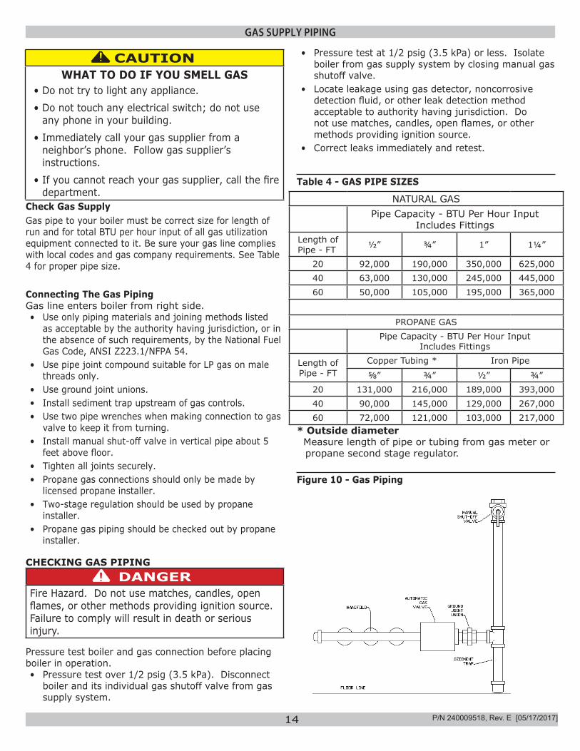
GAS SUPPLY PIPING
Check Gas SupplyGas pipe to your boiler must be correct size for length of run and for total BTU per hour input of all gas utilization equipment connected to it. Be sure your gas line complies with local codes and gas company requirements. See Table 4 for proper pipe size.
Connecting The Gas PipingGas line enters boiler from right side.• Use only piping materials and joining methods listed
as acceptable by the authority having jurisdiction, or in the absence of such requirements, by the National Fuel Gas Code, ANSI Z223.1/NFPA 54.
• Use pipe joint compound suitable for LP gas on male threads only.
• Use ground joint unions.• Install sediment trap upstream of gas controls.• Use two pipe wrenches when making connection to gas
valve to keep it from turning.• Install manual shut-off valve in vertical pipe about 5
feet above floor.• Tighten all joints securely.• Propane gas connections should only be made by
licensed propane installer.• Two-stage regulation should be used by propane
installer.• Propane gas piping should be checked out by propane
installer.
CHECKING GAS PIPINGDANGER
Fire Hazard. Do not use matches, candles, open flames, or other methods providing ignition source. Failure to comply will result in death or serious injury.
!
Pressure test boiler and gas connection before placing boiler in operation.• Pressure test over 1/2 psig (3.5 kPa). Disconnect
boiler and its individual gas shutoff valve from gas supply system.
NATURAL GASPipe Capacity - BTU Per Hour Input
Includes FittingsLength of Pipe - FT ½” ¾” 1” 1¼”
20 92,000 190,000 350,000 625,00040 63,000 130,000 245,000 445,00060 50,000 105,000 195,000 365,000
PROPANE GASPipe Capacity - BTU Per Hour Input
Includes Fittings
Length of Pipe - FT
Copper Tubing * Iron Pipe
⅝” ¾” ½” ¾”20 131,000 216,000 189,000 393,00040 90,000 145,000 129,000 267,00060 72,000 121,000 103,000 217,000
* Outside diameter Measure length of pipe or tubing from gas meter or
propane second stage regulator.
Table 4 - GAS PIPE SIZES
Figure 10 - Gas Piping
• Pressure test at 1/2 psig (3.5 kPa) or less. Isolate boiler from gas supply system by closing manual gas shutoff valve.
• Locate leakage using gas detector, noncorrosive detection fluid, or other leak detection method acceptable to authority having jurisdiction. Do not use matches, candles, open flames, or other methods providing ignition source.
• Correct leaks immediately and retest.
CAUTIONWHAT TO DO IF YOU SMELL GAS
• Do not try to light any appliance.• Do not touch any electrical switch; do not use
any phone in your building.• Immediately call your gas supplier from a
neighbor’s phone. Follow gas supplier’s instructions.
• If you cannot reach your gas supplier, call the fire department.
!
P/N 240009518, Rev. E [05/17/2017]
15
ELECTRICAL WIRING
Electrically bond boiler to ground in accordance with requirements of authority having jurisdiction. Refer to National Electrical Code, ANSI/NFPA 70.
ELECTRIC POWER SUPPLYRun separate 120 volt circuit from separate over current protective device in electrical service entrance panel. This should be a 15 ampere circuit. Locate shut-off switch at boiler. It must be turned off during any maintenance. Connect 120 volt power supply to control leads L1 (HOT) and L2.Run a 14 gauge or heavier copper wire from boiler to grounded connection in service panel or properly driven and electrically grounded ground rod.
THERMOSTAT INSTALLATION1. Thermostat should be installed on an inside wall about
four feet above the floor.2. NEVER install a thermostat on an outside wall. 3. Do not install a thermostat where it will be affected
by drafts, hot or cold pipes, sunlight, lighting fixtures, televisions, a fireplace, or a chimney.
4. Check thermostat operation by raising and lowering thermostat setting as required to start and stop the burners.
5. Instructions for the final adjustment of the thermostat are packaged with the thermostat (adjusting heating anticipator, calibration, etc.)
Set heat anticipator at .2 amps. 24 volt thermostat connects to aquastat terminals T and TV.
VENT DAMPER WIRINGBoiler is equipped with factory wired harness with 4 pin molex plug, that plugs into 4 pin molex receptacle inside vent damper operator.Vent damper must be connected for boiler to operate.
If original wire as supplied with this appliance must be replaced, replace with type 105°C thermoplastic wire or its equivalent.
WARNINGElectrical shock hazard. Turn OFF electrical power supply at service panel before making electrical connections. Failure to do so could result in death or serious injury.
!
NOTICELabel all wires prior to disconnection when servicing controls. Wiring errors can cause improper and dangerous operation. Verify proper operation after servicing.
P/N 240009518, Rev. E [05/17/2017]
16
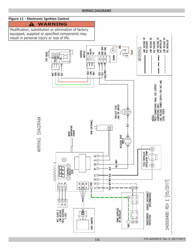
WIRING DIAGRAMS
Figure 11 - Electronic Ignition Control
WARNINGModification, substitution or elimination of factory equipped, supplied or specified components may result in personal injury or loss of life.
!
P/N 240009518, Rev. E [05/17/2017]
17
STARTING YOUR BOILER
FILLING SYSTEM WITH WATER• Close air vents on all radiation units. Open valves to
these units.
• Verify boiler and expansion tank drain valves are closed.
• Close drain fitting on air bleed screw.
• Open valve in line from boiler to expansion tank. Open water inlet to your boiler and leave it open. Start with lowest radiation unit. Open air vent on this unit. When all air has escaped and water starts to flow from vent, close it.
• Go to next radiation unit, and repeat process. Repeat until you have covered every radiation units in the system (ending up at highest unit in system).
• If your units have automatic vents, this manual venting is unnecessary but it will speed up the proper filling of your system.
• If your system is closed expansion tank system, you may leave it open to refill system automatically as needed.
• Check temperature pressure gauge. Not position of hand indicating pressure. This should be between 10 and 15 psi. Any lowering of this movable hand below 10 psi. indicates loss of water due to leakage. Automatic fill valve should compensate for this. Instructions are packaged with valve.
NOTICE
Never run water in a hot empty boiler.
P/N 240009518, Rev. E [05/17/2017]
18
LIGHTING INSTRUCTIONS
OFF
ONINLET
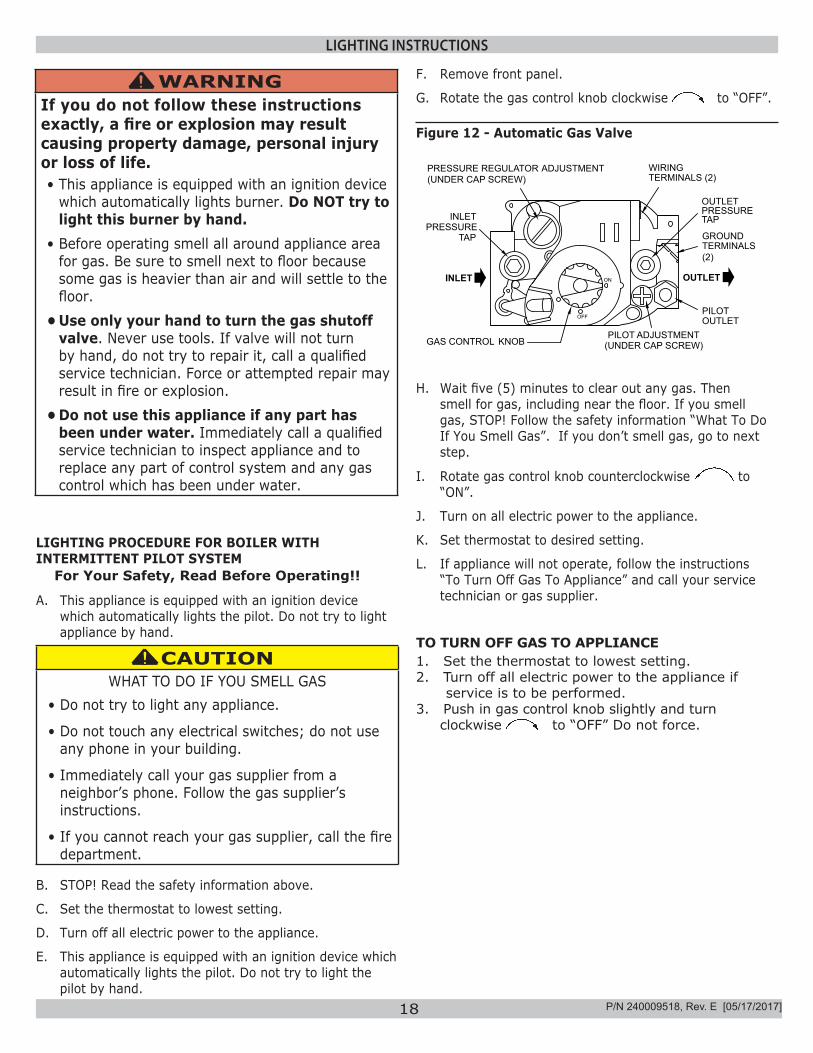
GAS CONTROL KNOBPILOT ADJUSTMENT
(UNDER CAP SCREW)
PILOT OUTLET
OUTLET
WIRINGTERMINALS (2)
INLETPRESSURE
TAPTERMINALS (2)
GROUND
PRESSURETAP
PRESSURE REGULATOR ADJUSTMENT(UNDER CAP SCREW)
OUTLET
F. Remove front panel.
G. Rotate the gas control knob clockwise to “OFF”.
TO TURN OFF GAS TO APPLIANCE 1. Set the thermostat to lowest setting.2. Turn off all electric power to the appliance if
service is to be performed.3. Push in gas control knob slightly and turn
clockwise to “OFF” Do not force.
WARNINGIf you do not follow these instructions exactly, a fire or explosion may result causing property damage, personal injury or loss of life.• This appliance is equipped with an ignition device
which automatically lights burner. Do NOT try to light this burner by hand.
• Before operating smell all around appliance area for gas. Be sure to smell next to floor because some gas is heavier than air and will settle to the floor.
• Use only your hand to turn the gas shutoff valve. Never use tools. If valve will not turn by hand, do not try to repair it, call a qualified service technician. Force or attempted repair may result in fire or explosion.
• Do not use this appliance if any part has been under water. Immediately call a qualified service technician to inspect appliance and to replace any part of control system and any gas control which has been under water.
!
LIGHTING PROCEDURE FOR BOILER WITH INTERMITTENT PILOT SYSTEM
For Your Safety, Read Before Operating!!
A. This appliance is equipped with an ignition device which automatically lights the pilot. Do not try to light appliance by hand.
CAUTIONWHAT TO DO IF YOU SMELL GAS
• Do not try to light any appliance.
• Do not touch any electrical switches; do not use any phone in your building.
• Immediately call your gas supplier from a neighbor’s phone. Follow the gas supplier’s instructions.
• If you cannot reach your gas supplier, call the fire department.
!
B. STOP! Read the safety information above.
C. Set the thermostat to lowest setting.
D. Turn off all electric power to the appliance.
E. This appliance is equipped with an ignition device which automatically lights the pilot. Do not try to light the pilot by hand.
Figure 12 - Automatic Gas Valve
H. Wait five (5) minutes to clear out any gas. Then smell for gas, including near the floor. If you smell gas, STOP! Follow the safety information “What To Do If You Smell Gas”. If you don’t smell gas, go to next step.
I. Rotate gas control knob counterclockwise to “ON”.
J. Turn on all electric power to the appliance.
K. Set thermostat to desired setting.
L. If appliance will not operate, follow the instructions “To Turn Off Gas To Appliance” and call your service technician or gas supplier.
P/N 240009518, Rev. E [05/17/2017]
19
OPERATING YOUR BOILER
AUTOMATIC GAS VALVEAutomatic Gas Valve opens or closes according to heat requirements of thermostat and temperature limit control. It closes if pilot goes out. Each individual control must be operating correctly before any gas can pass to burners. Any one control can hold gas supply from burner regardless of demand of any other control.
SAFETY PILOTSafety Pilot prevents flow of gas to burner if pilot goes out, or will not ignite.
GAS VALVE SAFETY SHUTDOWN TESTIgnition system safety shutoff device must be tested after placing boiler in operation.
RELIGHTElectric and gas shall be off for 5 minutes before relighting.
THERMOSTATKeep it set at desired room temperature. If windows are to be opened or heat is not needed, move thermostat pointer to lower setting.
NOTICEIn event of failure of any component, system will not operate or will go into safety lockout. System is completely self-checking. On every call for heat, each component must be functioning properly to permit operation. Safety lockout system has to be reset by turning thermostat to lowest setting for one minute, then back to normal setting.
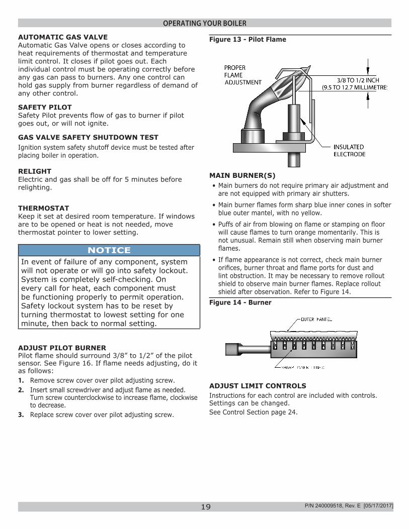
ADJUST PILOT BURNERPilot flame should surround 3/8” to 1/2” of the pilot sensor. See Figure 16. If flame needs adjusting, do it as follows:1. Remove screw cover over pilot adjusting screw.2. Insert small screwdriver and adjust flame as needed.
Turn screw counterclockwise to increase flame, clockwise to decrease.
3. Replace screw cover over pilot adjusting screw.
MAIN BURNER(S)• Main burners do not require primary air adjustment and
are not equipped with primary air shutters.
• Main burner flames form sharp blue inner cones in softer blue outer mantel, with no yellow.
• Puffs of air from blowing on flame or stamping on floor will cause flames to turn orange momentarily. This is not unusual. Remain still when observing main burner flames.
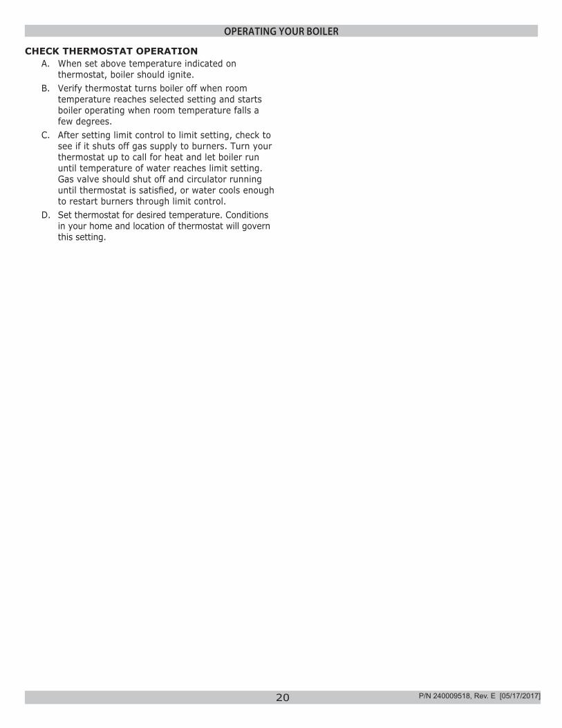
• If flame appearance is not correct, check main burner orifices, burner throat and flame ports for dust and lint obstruction. It may be necessary to remove rollout shield to observe main burner flames. Replace rollout shield after observation. Refer to Figure 14.
Figure 14 - Burner
ADJUST LIMIT CONTROLSInstructions for each control are included with controls. Settings can be changed. See Control Section page 24.
Figure 13 - Pilot Flame
P/N 240009518, Rev. E [05/17/2017]
20
OPERATING YOUR BOILER
CHECK THERMOSTAT OPERATIONA. When set above temperature indicated on
thermostat, boiler should ignite. B. Verify thermostat turns boiler off when room
temperature reaches selected setting and starts boiler operating when room temperature falls a few degrees.
C. After setting limit control to limit setting, check to see if it shuts off gas supply to burners. Turn your thermostat up to call for heat and let boiler run until temperature of water reaches limit setting. Gas valve should shut off and circulator running until thermostat is satisfied, or water cools enough to restart burners through limit control.
D. Set thermostat for desired temperature. Conditions in your home and location of thermostat will govern this setting.
P/N 240009518, Rev. E [05/17/2017]
21
OPERATING THE BOILER - SYSTEM START-UP
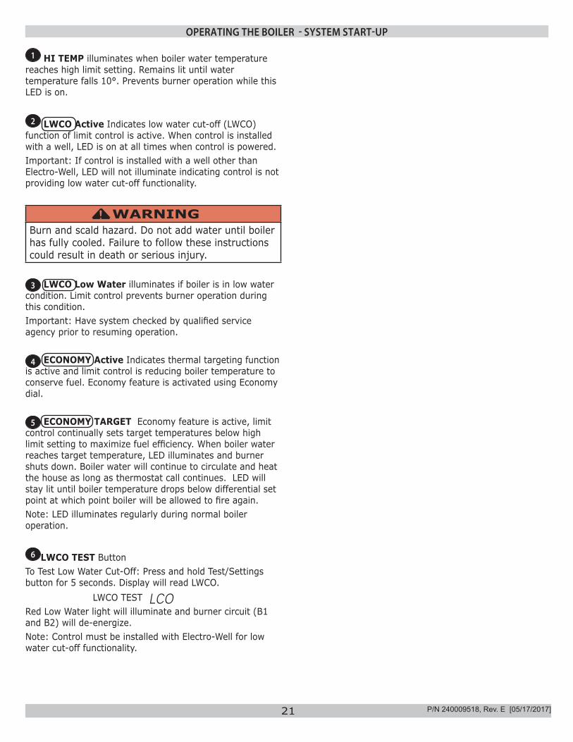
1 HI TEMP illuminates when boiler water temperature reaches high limit setting. Remains lit until water temperature falls 10°. Prevents burner operation while this LED is on.
2 LWCO Active Indicates low water cut-off (LWCO) function of limit control is active. When control is installed with a well, LED is on at all times when control is powered. Important: If control is installed with a well other than Electro-Well, LED will not illuminate indicating control is not providing low water cut-off functionality.
WARNINGBurn and scald hazard. Do not add water until boiler has fully cooled. Failure to follow these instructions could result in death or serious injury.
!
3 LWCO Low Water illuminates if boiler is in low water condition. Limit control prevents burner operation during this condition. Important: Have system checked by qualified service agency prior to resuming operation.
4 ECONOMY Active Indicates thermal targeting function is active and limit control is reducing boiler temperature to conserve fuel. Economy feature is activated using Economy dial.
5 ECONOMY TARGET Economy feature is active, limit control continually sets target temperatures below high limit setting to maximize fuel efficiency. When boiler water reaches target temperature, LED illuminates and burner shuts down. Boiler water will continue to circulate and heat the house as long as thermostat call continues. LED will stay lit until boiler temperature drops below differential set point at which point boiler will be allowed to fire again. Note: LED illuminates regularly during normal boiler operation.
6 LWCO TEST Button To Test Low Water Cut-Off: Press and hold Test/Settings button for 5 seconds. Display will read LWCO. LWCO TEST LCORed Low Water light will illuminate and burner circuit (B1 and B2) will de-energize. Note: Control must be installed with Electro-Well for low water cut-off functionality.
P/N 240009518, Rev. E [05/17/2017]
22
OPERATING THE BOILER - SYSTEM START-UP
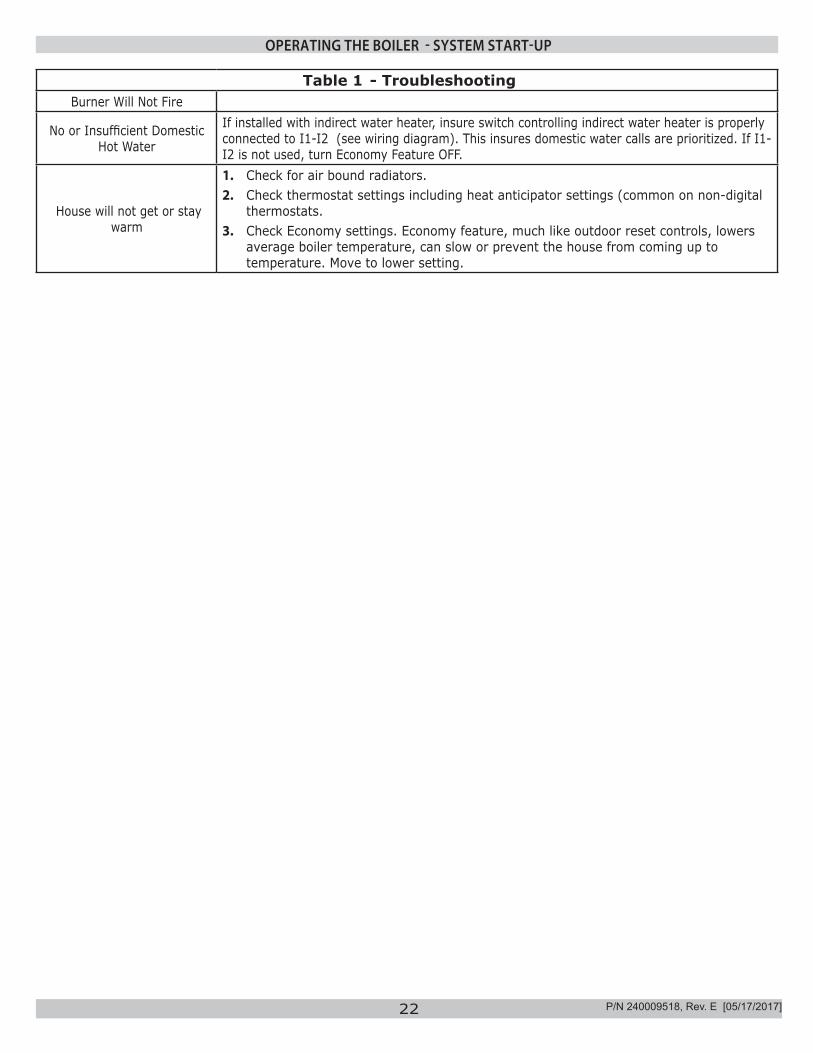
Table 1 - TroubleshootingBurner Will Not Fire
No or Insufficient Domestic Hot Water
If installed with indirect water heater, insure switch controlling indirect water heater is properly connected to I1-I2 (see wiring diagram). This insures domestic water calls are prioritized. If I1-I2 is not used, turn Economy Feature OFF.
House will not get or stay warm
1. Check for air bound radiators.2. Check thermostat settings including heat anticipator settings (common on non-digital
thermostats.3. Check Economy settings. Economy feature, much like outdoor reset controls, lowers
average boiler temperature, can slow or prevent the house from coming up to temperature. Move to lower setting.
P/N 240009518, Rev. E [05/17/2017]
23
EQUIPMENT AND OPTIONAL ACCESSORIES - WHAT THEY DOSERVICE HINTS
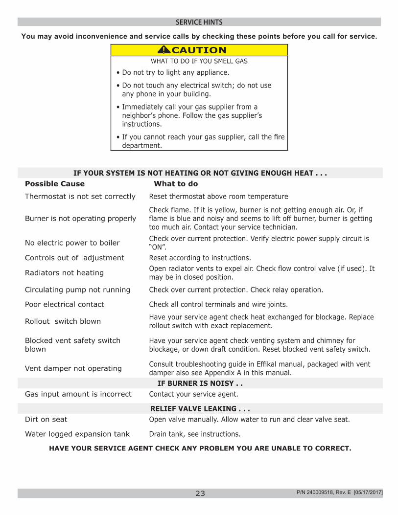
You may avoid inconvenience and service calls by checking these points before you call for service.
CAUTIONWHAT TO DO IF YOU SMELL GAS
• Do not try to light any appliance.
• Do not touch any electrical switch; do not use any phone in your building.
• Immediately call your gas supplier from a neighbor’s phone. Follow the gas supplier’s instructions.
• If you cannot reach your gas supplier, call the fire department.
!
IF YOUR SYSTEM IS NOT HEATING OR NOT GIVING ENOUGH HEAT . . .Possible Cause What to do
Thermostat is not set correctly Reset thermostat above room temperature
Burner is not operating properlyCheck flame. If it is yellow, burner is not getting enough air. Or, if flame is blue and noisy and seems to lift off burner, burner is getting too much air. Contact your service technician.
No electric power to boiler Check over current protection. Verify electric power supply circuit is “ON”.
Controls out of adjustment Reset according to instructions.
Radiators not heating Open radiator vents to expel air. Check flow control valve (if used). It may be in closed position.
Circulating pump not running Check over current protection. Check relay operation.
Poor electrical contact Check all control terminals and wire joints.
Rollout switch blown Have your service agent check heat exchanged for blockage. Replace rollout switch with exact replacement.
Blocked vent safety switch blown
Have your service agent check venting system and chimney for blockage, or down draft condition. Reset blocked vent safety switch.
Vent damper not operating Consult troubleshooting guide in Effikal manual, packaged with vent damper also see Appendix A in this manual.
IF BURNER IS NOISY . .Gas input amount is incorrect Contact your service agent.
RELIEF VALVE LEAKING . . .Dirt on seat Open valve manually. Allow water to run and clear valve seat.
Water logged expansion tank Drain tank, see instructions.
HAVE YOUR SERVICE AGENT CHECK ANY PROBLEM YOU ARE UNABLE TO CORRECT.
P/N 240009518, Rev. E [05/17/2017]
24
MAINTAINING YOUR BOILER
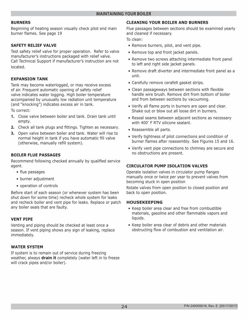
BURNERSBeginning of heating season visually check pilot end main burner flames. See page 19
SAFETY RELIEF VALVETest safety relief valve for proper operation. Refer to valve manufacturer’s instructions packaged with relief valve. Call Technical Support if manufacturer’s instruction are not located.
EXPANSION TANKTank may become waterlogged, or may receive excess of air. Frequent automatic opening of safety relief valve indicates water logging. High boiler temperature accompanied by unusually low radiation unit temperature (and “knocking”) indicates excess air in tank.To correct:1. Close valve between boiler and tank. Drain tank until
empty. 2. Check all tank plugs and fittings. Tighten as necessary. 3. Open valve between boiler and tank. Water will rise to
normal height in tank if you have automatic fill valve (otherwise, manually refill system).
BOILER FLUE PASSAGESRecommend following checked annually by qualified service agent.
• flue passages
• burner adjustment
• operation of controls
Before start of each season (or whenever system has been shut down for some time) recheck whole system for leaks and recheck boiler and vent pipe for leaks. Replace or patch any boiler seals that are faulty.
VENT PIPEVenting and piping should be checked at least once a season. If vent piping shows any sign of leaking, replace immediately.
WATER SYSTEMIf system is to remain out of service during freezing weather, always drain it completely (water left in to freeze will crack pipes and/or boiler).
CLEANING YOUR BOILER AND BURNERSFlue passages between sections should be examined yearly and cleaned if necessary. To clean: • Remove burners, pilot, and vent pipe.
• Remove top and front jacket panels.
• Remove two screws attaching intermediate front panel to left and right side jacket panels.
• Remove draft diverter and intermediate front panel as a unit.
• Carefully remove cerafelt gasket strips.
• Clean passageways between sections with flexible handle wire brush. Remove dirt from bottom of boiler and from between sections by vacuuming.
• Verify all flame ports in burners are open and clear. Shake out or blow out all loose dirt in burners.
• Reseal seams between adjacent sections as necessary with 400° F RTV silicone sealant.
• Reassemble all parts.
• Verify tightness of pilot connections and condition of burner flames after reassembly. See Figures 15 and 16.
• Verify vent pipe connections to chimney are secure and no obstructions are present.
CIRCULATOR PUMP ISOLATION VALVESOperate isolation valves in circulator pump flanges manually once or twice per year to prevent valves from becoming stuck in open position Rotate valves from open position to closed position and back to open position.
HOUSEKEEPING• Keep boiler area clear and free from combustible
materials, gasoline and other flammable vapors and liquids.
• Keep boiler area clear of debris and other materials obstructing flow of combustion and ventilation air.
P/N 240009518, Rev. E [05/17/2017]
25
EQUIPMENT AND OPTIONAL ACCESSORIES
WARNINGBurn and scald hazard. Safety relief valve could discharge steam or hot water during operation. Install discharge piping per these instructions.
!
SAFETY RELIEF VALVESafety relief valve is required on your boiler. Water expands as it is heated. If there is no place for water to expand into, water pressure will build up inside boiler and system. Should this happen, safety relief valve will automatically open at predetermined pressure. This will relieve the strain on boiler and system. Run pipe from relief valve outlet (pipe must be same size as outlet and open end must not be threaded) to open drain, tub or sink, or other suitable drainage point not subject to freezing. Failure to do so may cause water damage or injury should safety relief valve release.
EXPANSION TANKExpanding water flows into expansion tank. Tank should be correct size. Tank is filled with air. As water expands it compresses air in the tank to form air pressure cushion. This “spring-like” cushion serves to maintain correct operating water pressure regardless of water temperature. This assures “full measure” of water, even in highest radiation unit of system. It also prevents blowing off of safety relief valve. Air in tank in beginning (with system filled with cold water) is sufficient for proper operation. Tank also serves as trap for excess air in system. Air would cause gurgling in pipes and in efficient circulation in radiators if left in system.It is possible for tank to become “waterlogged” (filled with water). It can also become overfilled with air. This can happen after filling system with new water. Fittings provided on tank and in line to tank are for bleeding off excess water or air. When installing this tank, it is important: 1. Tank be higher than boiler top. 2. Pipe to tank continuously rises up to tank (so air
can “bubble” up to it).
DIAPHRAGM TYPE EXPANSION TANKDiaphragm type expansion tank takes place of conventional expansion tank. Carefully read instructions packed with your tank assembly. Tank comes with 10-12 pounds per square inch air charge. This is the same as pressure produced in system by automatic fill valve. When system is first filled, tank will contain little or no water. As water is heated its pressure increases. It expands into tank, compressing air in tank. Compressed air cushion permits water in system to expand as temperature changes. Diaphragm type tank can be mounted on air purger fitting or at any convenient place in supply or return line.
AIR ELIMINATING FITTING (AIR PURGER)Air purger is used to remove excess air from system. It is installed in supply line. It will eliminate air from water before it reaches radiators and bleed off this air.
MAIN AIR VENT FOR DOWN FLOW SYSTEMS OR DIAPHRAGM TYPE EXPANSION TANKBefore system is filled with water, there is air in pipes and radiation units. Some of it will be trapped as system is filled . It is possible to eliminate most of this air through air vent on radiation units. Main air vent will speed and simplify this. Install on highest point in supply main when all radiation is below top of boiler.
AUTOMATIC FILL VALVEFor a safe, efficient operation, hot water system must be completely filled with water. Adding new water, when needed can be done manually (by use of hand valve in water supply line). Requires regular attention to system’s needs. Automatic fill valve accomplishes this without attention. Install in supply line on hot water boilers only. Valve operates through water pressure differentials. It does not require electrical connection.
DRAIN VALVEManual valve provides means of draining all water from boiler and system. It is often installed in 3/4” tapping at bottom of end boiler section. Or it can be installed in tee where return line enters boiler.
CIRCULATING PUMPEvery forced hot-water system requires circulating pump. Separate pump or zone valve is required for each zone, if you have a two or more zone system. Pump must have capacity to provide circulation required by your system. Pump is connected into main just ahead of boiler. It is also wired to electrical system.
VENT DAMPERThis product is automatic, motorized stack damper developed to increase efficiency of heating system by reducing standby losses from heating apparatus and conditioned air space. Damper closes chimney vent when burner is off and fully opens it when combustion is required.
P/N 240009518, Rev. E [05/17/2017]
26
BLOCKED VENT SAFETY SWITCH(BLOCKED VENT SAFETY SHUTOFF)Blocked vent safety switch is manual reset disc thermostat with fixed setpoint (340°F), and normally closed contacts. It is located at relief opening of integral draft diverter. In event of chimney or venting system blockage causing products of combustion to spill out of relief opening, blocked vent safety switch disc heats up and blocked vent safety switch contacts open, shutting down flow of gas to main burners by removing power to gas valve. In event blocked vent safety switch contacts open, reset button on back of switch will pop up. Blocked vent safety switch must be reset manually, after switch has cooled off, by pushing reset button down. Check venting system and chimney for blockage when restoring system to operating condition. DO NOT operate boiler without blocked vent safety switch.
ROLLOUT SWITCH (FLAME ROLLOUT SAFETY SHUTOFF)Rollout switch is temperature-sensitive fuse link device. Located on boiler base just outside fire box. In event of heat exchanger flueway blockage causing flame to roll out of fire box, fuse does not change in appearance when blown.If rollout switch blows, it must be replaced with exact replacement. Check heat exchanger flueways for blockage when restoring system to operating condition. DO NOT operate system without rollout switch.
EQUIPMENT AND OPTIONAL ACCESSORIES
P/N 240009518, Rev. E [05/17/2017]
27
APPENDIX A - CONTROL MODULE
INTERMITTENT PILOTIgnition System Checks
STEP 1: Check ignition cable.• Verify ignition cable does not touch metal surfaces.
• Verify only factory supplied Ignition cable (or approved replacement) is used.
• Verify connections to ignition module and igniter or igniter-sensor are clean and tight.
• Verify ignition cable provides good electrical continuity.
STEP 2:Verify ignition system grounding. Nuisance shutdowns are often caused poor or erratic grounding.Common ground is required for module and pilot burner/igniter sensor.
— Check for good metal-to-metal contact between pilot burner bracket and the main burner.— Check ground lead from GND (BURNER) terminal
on module to pilot burner. Verify connections are clean and tight. If wire is damaged or deteriorated, replace with No. 14-18 gauge, moisture-resistant, thermoplastic insulated wire with 105°C [221°F] minimum rating.
— Check ceramic flame rod insulator for cracks or evidence of exposure to extreme heat, which can permit leakage to ground. Replace pilot burner/igniter sensor and provide shield if necessary.
— If flame rod or bracket is bent out of position, restore to correct position.
STEP 3: Check spark ignition circuit. Disconnect ignition cable at SPARK terminal on module.
WARNINGElectrical shock hazard. Ignition circuit generates over 10,000 volts. Turn OFF electrical power supply at service panel before making electrical connections. Failure to do so could result in death or serious injury.
!
Energize module and listen for audible sparking noise. When operating normally, there should be buzzing noise turns on and off twice per second for duration of 1–7 seconds, depending on model.
STEP 4: Verify pilot and main burner light-off.• Initiate call for heat. Turn thermostat above room
temperature. Ignition sequence may be delayed by thermal purge until boiler water temperature is below 140°F (60°C)
• Watch pilot burner during ignition sequence:
— Verify ignition spark continues after pilot is lit.— Verify pilot lights and spark stops, verify main
burner does not light.• If so, ensure adequate flame current as follows:
— Turn off boiler at circuit breaker or fuse box.— Clean flame rod with emery cloth.— Verify electrical connections are clean and tight.
Replace damaged wire..— Check for cracked ceramic insulator, which can
cause short to ground, and replace igniter-sensor if necessary.
— At gas valve, disconnect main valve wire from MV terminal.
— Turn on power and set thermostat to call for heat. Pilot should light, main burner will remain off because main valve actuator is disconnected.
— Check pilot flame. Verify it is blue, steady and envelops 3/8 to 1/2 in. [10 to 13 mm] of flame rod. See Figure 15 for possible flame problems and causes.
— If necessary, adjust pilot flame by turning pilot adjustment screw on gas control clockwise to decrease or counterclockwise to increase pilot flame. Following adjustment, always replace pilot adjustment cover screw and tighten firmly to assure proper gas control operation. Figure 12, page 18.
— Set temperature below room set-point to end call for heat.
P/N 240009518, Rev. E [05/17/2017]
28
APPENDIX A - CONTROL MODULE
• Recheck ignition sequence as follows:
— Reconnect main valve wire.— Adjust thermostat above room temperature.— Verify ignition sequence at burner.— If spark does not stop after pilot lights, replace
module.— If main burner does not light or if main burner lights
and system locks out, check module, ground wire and gas control as described in troubleshooting table. See Table 7 page 30, and Table 8 page 31.
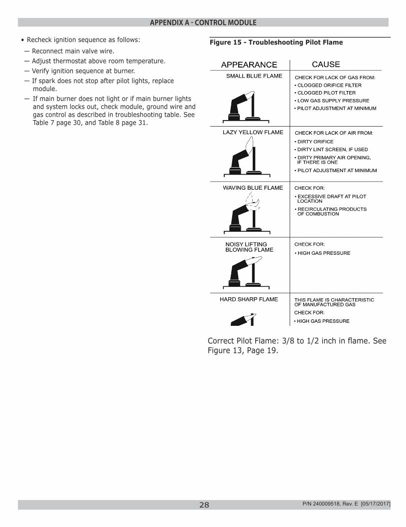
Figure 15 - Troubleshooting Pilot Flame
Correct Pilot Flame: 3/8 to 1/2 inch in flame. See Figure 13, Page 19.
P/N 240009518, Rev. E [05/17/2017]
29
APPENDIX A-1 - VENT DAMPER HARNESS
A.1 VENT DAMPER HARNESS - MOLEX PLUGS WARNING
Do Not negate the action of any existing safety orperational controls. Avoidance of these instructions could result in death or serious injury.
!
NoteWhen servicing controls, all wires must be labeled prior to disconnection. Wiring errors can cause improper and dangerous operation. Do not turn damper open manually or motor damage will result and void all warranties, use the service switch.
DO NOT CUT PLUG OFF OF DAMPER MOTOR ASSEMBLY OR WARRANTY WILL BE VOID.
Check Molex Plugs on Vent Damper Harness:
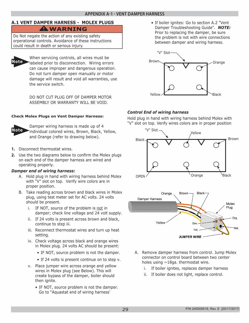
NoteDamper wiring harness is made up of 4 individual colored wires, Brown, Black, Yellow, and Orange (refer to drawing below).
1. Disconnect thermostat wires.2. Use the two diagrams below to confirm the Molex plugs
on each end of the damper harness are wired and operating properly.
Damper end of wiring harness:A. Hold plug in hand with wiring harness behind Molex
with “V” slot on top. Verify wire colors are in proper position.
B. Take reading across brown and black wires in Molex plug, using test meter set for AC volts. 24 volts should be present. i. IF NOT, source of the problem is not in
damper; check line voltage and 24 volt supply.ii. If 24 volts is present across brown and black,
continue to step iii.iii. Reconnect thermostat wires and turn up heat
setting.iv. Check voltage across black and orange wires
in Molex plug. 24 volts AC should be present:• IF NOT, source problem is not the damper.
• If 24 volts is present continue on to step v.v. Place jumper wire across orange and yellow
wires in Molex plug (see Below). This will create bypass of the damper, boiler should then ignite. • IF NOT, source problem is not the damper.
Go to “Aquastat end of wiring harness’
Brown
Yellow
Orange
Black
"V" Slot
Control End of wiring harness Hold plug in hand with wiring harness behind Molex with “V” slot on top. Verify wires colors are in proper position
OPEN
Black
"V" SlotYellow
Brown
Orange Black
A. Remove damper harness from control. Jump Molex connector on control board between two center holes using ~18ga. thermostat wire.i. If boiler ignites, replaces damper harnessii. If boiler does not light, replace control.
• If boiler ignites: Go to section A.2 "Vent Damper Troubleshooting Guide". NOTE: Prior to replacing the damper, be sure the problem is not with wire connections between damper and wiring harness.
P/N 240009518, Rev. E [05/17/2017]
30
APPENDIX A-2 - VENT DAMPER TROUBLESHOOTING
A.2 Vent Damper Troubleshooting Guide
WARNINGDo Not negate the action of any existing safety orperational controls. Avoidance of these instructions could result in death or serious injury.
!
NoteWhen servicing controls, all wires must be labeled prior to disconnection. Wiring errors can cause improper and dangerous operation. Do not turn damper open maunually or motor damage will result and void all warranties, use the service switch.
DO NOT CUT PLUG OFF OF DAMPER MOTOR ASSEMBLY OR WARRANTY WILL BE VOID.
NORMAL SEQUENCE OF OPERATION
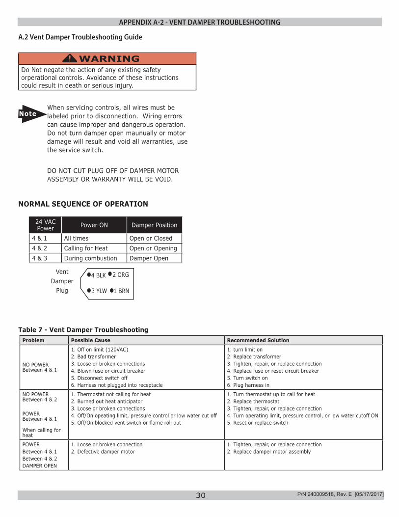
24 VAC Power Power ON Damper Position
4 & 1 All times Open or Closed4 & 2 Calling for Heat Open or Opening4 & 3 During combustion Damper Open
Vent Damper
Plug
4 BLK
3 YLW
2 ORG
1 BRN
Problem Possible Cause Recommended Solution
NO POWER Between 4 & 1
1. Off on limit (120VAC)2. Bad transformer3. Loose or broken connections4. Blown fuse or circuit breaker5. Disconnect switch off6. Harness not plugged into receptacle
1. turn limit on2. Replace transformer3. Tighten, repair, or replace connection4. Replace fuse or reset circuit breaker5. Turn switch on6. Plug harness in
NO POWERBetween 4 & 2
POWERBetween 4 & 1
When calling for heat
1. Thermostat not calling for heat2. Burned out heat anticipator3. Loose or broken connections4. Off/On opeating limit, pressure control or low water cut off5. Off/On blocked vent switch or flame roll out
1. Turn thermostat up to call for heat2. Replace thermostat3. Tighten, repair, or replace connection4. Turn operating limit, pressure control, or low water cutoff ON5. Reset or replace switch
POWERBetween 4 & 1Between 4 & 2DAMPER OPEN
1. Loose or broken connection2. Defective damper motor
1. Tighten, repair, or replace connection2. Replace damper motor assembly
Table 7 - Vent Damper Troubleshooting
P/N 240009518, Rev. E [05/17/2017]
31
APPENDIX A-2 - VENT DAMPER TROUBLESHOOTING
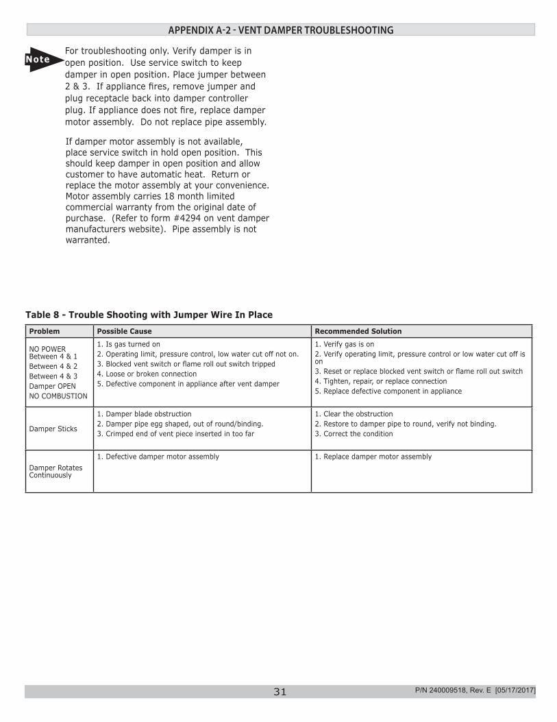
Problem Possible Cause Recommended Solution
NO POWER Between 4 & 1Between 4 & 2Between 4 & 3Damper OPENNO COMBUSTION
1. Is gas turned on2. Operating limit, pressure control, low water cut off not on.3. Blocked vent switch or flame roll out switch tripped4. Loose or broken connection5. Defective component in appliance after vent damper
1. Verify gas is on2. Verify operating limit, pressure control or low water cut off is on3. Reset or replace blocked vent switch or flame roll out switch4. Tighten, repair, or replace connection5. Replace defective component in appliance
Damper Sticks
1. Damper blade obstruction2. Damper pipe egg shaped, out of round/binding.3. Crimped end of vent piece inserted in too far
1. Clear the obstruction2. Restore to damper pipe to round, verify not binding.3. Correct the condition
Damper Rotates Continuously
1. Defective damper motor assembly 1. Replace damper motor assembly
NoteFor troubleshooting only. Verify damper is in open position. Use service switch to keep damper in open position. Place jumper between 2 & 3. If appliance fires, remove jumper and plug receptacle back into damper controller plug. If appliance does not fire, replace damper motor assembly. Do not replace pipe assembly.
If damper motor assembly is not available, place service switch in hold open position. This should keep damper in open position and allow customer to have automatic heat. Return or replace the motor assembly at your convenience. Motor assembly carries 18 month limited commercial warranty from the original date of purchase. (Refer to form #4294 on vent damper manufacturers website). Pipe assembly is not warranted.
Table 8 - Trouble Shooting with Jumper Wire In Place
P/N 240009518, Rev. E [05/17/2017]
DUNKIRK BOILERS2201 Dwyer Avenue, Utica NY 13501web site: www.ecrinternational.com
DUNKIRK BOILERS2201 Dwyer Avenue, Utica NY 13501web site: www.ecrinternational.com
IMPORTANT
In accordance with Section 325 (f) (3) of the Energy Policy and Conservation Act, this boiler is equipped with a feature that saves energy by reducing the boiler water temperature as the heating load decreases. This feature is equipped with an override
which is provided primarily to permit the use of an external energy management system that serves the same function.
THIS OVERRIDE MUST NOT BE USED UNLESS AT LEAST ONE OF THE FOLLOWING CONDITIONS IS TRUE:
• An external energy management system is installed that reduces the boiler water temperature as the heating load decreases.
• This boiler is not used for any space heating• This boiler is part of a modular or multiple boiler system having a total input of 300,000 BTU/hr or greater.• This boiler is equipped with a tankless coil.