modern blast furnace design - millennium...
TRANSCRIPT

35
IronmakIng, EnErgy and thE EnvIronmEnt
MIL
LEN
NIU
M S
TEEL
201
6
Modern blast furnace designBlast furnace operations have developed towards higher levels of pulverised coal injection and must operate on lower quality raw materials and more frequent fluctuations in production levels. These operating conditions introduce increased thermal, mechanical and chemical loading on the blast furnace lining. Modern blast furnaces should be able to cope with these increasing demands, and the target campaign life of new designs is over 20 years at an availability of over 95%. This can only be achieved if the internal profile of the blast furnace is maintained during the campaign, as any degradation will immediately have a negative effect on process stability and campaign life.
INTRODUCTIONLow-cost hot metal requires:` Low coke rate < 300kg/THM` High fuel injection rate > 200kg/THM` High availability > 95%
The blast furnace must also be able to cope with various raw material compositions of sinter, pellets and lump ore.
Determining the sizing and profiling parameters of a new blast furnace and maintaining these parameters during the campaign are critical to enable low-cost hot metal operations. These parameters include, for example, throat, belly and hearth diameter, bosh and stack angle, working height, sump depth and number of tuyeres. Blast furnace design has had many improvements in recent decades and campaigns of more than 20 years are recorded to date.
Examples of two modern blast furnace designs are illustrated in Figure 1. The difference between these designs is the use of either copper stave coolers (right) or copper plate coolers (left) in the bosh, belly and stack areas.
This article will address each section of the blast furnace design covering:1. Bottom and hearth2. Tuyere area3. Bosh, belly, lower and middle stack4. Upper stack and throat armour
BOTTOM AND HEARTHThe bottom and hearth performance is the limiting factor at many existing plants and usually determines the timing of relines or interim and partial repairs. This is due mainly to the fact that the working volume and production were increased during previous relines, while increases in hearth size were limited due to casthouse and foundation constraints. The hearth ‘productivity’ will then effectively increase, while the hearth volume is also reduced at low
Authors: Reinoud van Laar and Edo EngelDanieli Corus
r Fig 1 Modern blast furnace designs
coke rate due to a reduction in the permeability of the hearth. General hearth failure observations, which are shared in our industry, can be summarised as:
` Deformation and cracking of shell` Tuyere cooler displacement` Refractory brittle layer and cracking ` Refractory erosion, oxidation, etc.` Displacement of blocks` Break-outs
We have been monitoring and assessing the performance of various hearth designs and operations worldwide, including large block and hot-pressed brick designs, and including bottom air, water and oil cooling, as well as hearth shell spray, jacket and cast iron stave cooling.
The operating range included all-coke as well as low-coke ultra-high PCI operations, dry-hearth and single taphole operations and low-grade to high-grade raw materials (pellets, sinter, lump ore and combinations thereof). a
36
MIL
LEN
NIU
M S
TEEL
201
6
Advanced CFD modelling and two-phase flow experiments have been developed to simulate the hearth operations and process and demonstrate significant hot metal and slag flow and velocity differences depending on the geometry, tapping cycle and hearth voidage.
It is important to design a large hearth volume to support stable operations. Also, a stable casthouse practice is required to minimise liquid level fluctuations. The hearth volume can be increased by adopting conical shell segments instead of a cylindrical shell, although the hearth diameter at the tuyere level will have to be in proportion with the intended production level.
The shell and bottom seal-plate must be protected, and water cooling has demonstrated to be the most effective method if considering:` Cooling efficiency and capacity` Design redundancy and maintenance` Capital investment and operational costs
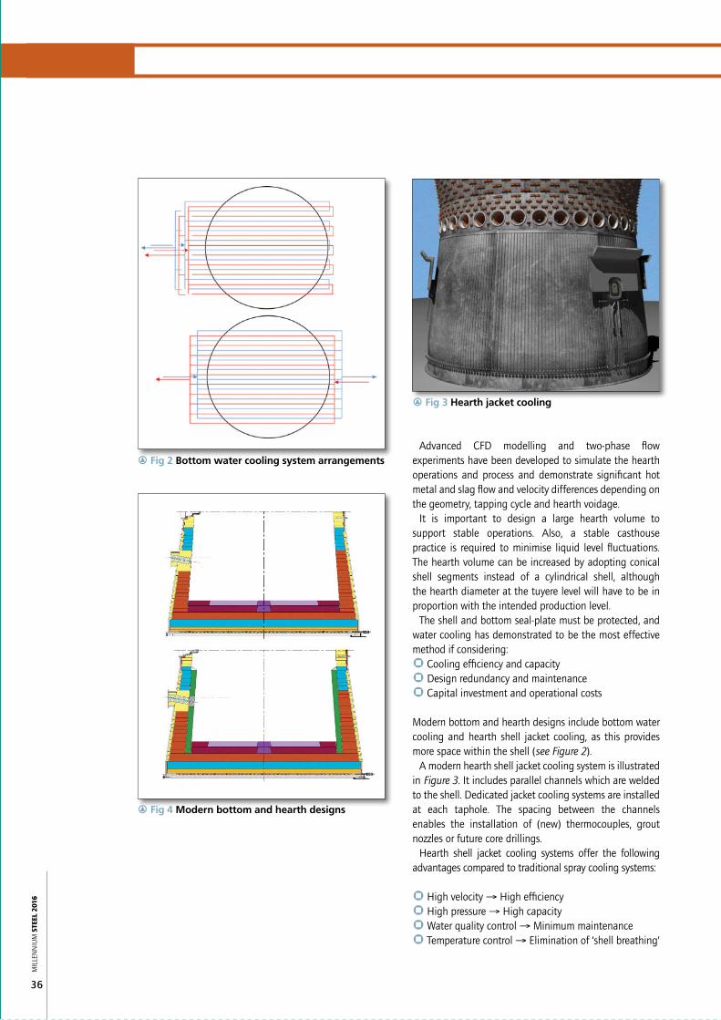
Modern bottom and hearth designs include bottom water cooling and hearth shell jacket cooling, as this provides more space within the shell (see Figure 2).
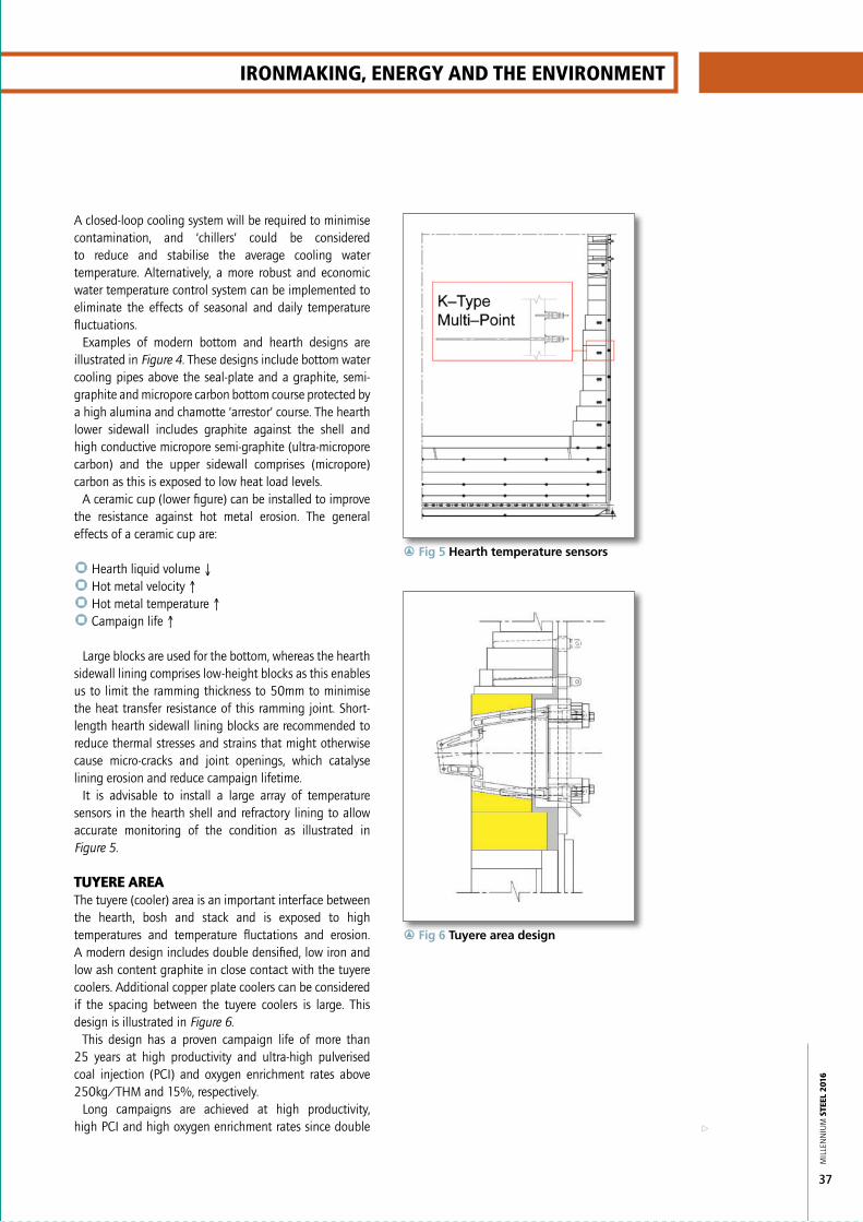
A modern hearth shell jacket cooling system is illustrated in Figure 3. It includes parallel channels which are welded to the shell. Dedicated jacket cooling systems are installed at each taphole. The spacing between the channels enables the installation of (new) thermocouples, grout nozzles or future core drillings.
Hearth shell jacket cooling systems offer the following advantages compared to traditional spray cooling systems:
` High velocity → High efficiency` High pressure → High capacity` Water quality control → Minimum maintenance` Temperature control → Elimination of ‘shell breathing’
r Fig 3 Hearth jacket cooling
r Fig 2 Bottom water cooling system arrangements
r Fig 4 Modern bottom and hearth designs
37
a
IronmakIng, EnErgy and thE EnvIronmEnt
MIL
LEN
NIU
M S
TEEL
201
6
A closed-loop cooling system will be required to minimise contamination, and ‘chillers’ could be considered to reduce and stabilise the average cooling water temperature. Alternatively, a more robust and economic water temperature control system can be implemented to eliminate the effects of seasonal and daily temperature fluctuations.
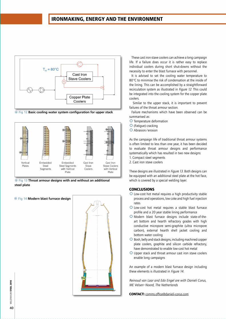
Examples of modern bottom and hearth designs are illustrated in Figure 4. These designs include bottom water cooling pipes above the seal-plate and a graphite, semi-graphite and micropore carbon bottom course protected by a high alumina and chamotte ‘arrestor’ course. The hearth lower sidewall includes graphite against the shell and high conductive micropore semi-graphite (ultra-micropore carbon) and the upper sidewall comprises (micropore) carbon as this is exposed to low heat load levels.
A ceramic cup (lower figure) can be installed to improve the resistance against hot metal erosion. The general effects of a ceramic cup are:
` Hearth liquid volume ↓` Hot metal velocity ↑` Hot metal temperature ↑` Campaign life ↑↑
Large blocks are used for the bottom, whereas the hearth sidewall lining comprises low-height blocks as this enables us to limit the ramming thickness to 50mm to minimise the heat transfer resistance of this ramming joint. Short-length hearth sidewall lining blocks are recommended to reduce thermal stresses and strains that might otherwise cause micro-cracks and joint openings, which catalyse lining erosion and reduce campaign lifetime.
It is advisable to install a large array of temperature sensors in the hearth shell and refractory lining to allow accurate monitoring of the condition as illustrated in Figure 5.
TUYERE AREAThe tuyere (cooler) area is an important interface between the hearth, bosh and stack and is exposed to high temperatures and temperature fluctations and erosion. A modern design includes double densified, low iron and low ash content graphite in close contact with the tuyere coolers. Additional copper plate coolers can be considered if the spacing between the tuyere coolers is large. This design is illustrated in Figure 6.
This design has a proven campaign life of more than 25 years at high productivity and ultra-high pulverised coal injection (PCI) and oxygen enrichment rates above 250kg/THM and 15%, respectively.
Long campaigns are achieved at high productivity, high PCI and high oxygen enrichment rates since double
r Fig 5 Hearth temperature sensors
r Fig 6 Tuyere area design

38
MIL
LEN
NIU
M S
TEEL
201
6
densified, low iron and low ash content graphite has a very high oxidation threshold temperature compared to other carbonaceous and graphite grades. Furthermore, combining high conductive graphite and high efficiency tuyere coolers and copper plate coolers will result in low hot face temperatures, as illustrated in Figure 7, thus preventing the risk of oxidation.
BOSH, BELLY, LOWER/MIDDLE STACKA blast furnace is a high-temperature, pressurised counter-current reactor. Abrasive raw materials are descending and gradually soften due to smelting, while high temperature gases are ascending through the burden, but also along the lining. The raceway flame temperature at the tuyeres is >2,000°C and the blast furnace operational pressure is 2-4 Bar(g). This can result in high thermal loadings to the lining.
The blast furnace is a continuous process, but with batch elements, such as charging and tapping. Furthermore, the process is sensitive to destabilisation due to variations in raw material quality, equipment failures, (unscheduled) shut-downs, burden slips, casting deficiencies and ‘gas-jets’. This results in dynamic process conditions.
The campaign life of traditional blast furnaces has, therefore, been limited to only a few years until modern lining designs were developed after the 1970s, including cast iron and copper stave cooling and copper plate cooling and refractory.
The performance of the designs depends on the application and local process conditions and operations.
Cast iron stave coolers cannot cope with high temperatures and high temperature fluctuations, as this will cause material degradation and cracking despite many improvements of coating, cast iron grade and refractory inserts. The application of cast iron stave coolers in the upper stack and throat armour, however, have proven to be very successful as this area is usually not exposed to high temperatures or temperature fluctuations. These areas face mainly abrasion due to the descending burden, and impact due to (incorrect) charging practice. Cast iron stave coolers and silicon carbide refractory inserts have a good resistance against abrasion/erosion and impact and are thus preferred in the upper stack and throat armour.
Copper stave coolers have been developed since the 1980s and are currently installed in many plants in high-thermal load zones such as the bosh, belly and lower stack.
In our recent history many plants have been reporting failure of copper stave coolers. Research has demonstrated that the root cause of failure is abrasion by descending burden, particularly coke. An example is shown in Figure 8.
This implies that the copper stave coolers are not adequately protected by an accretion, which contradicts classical theory.
r Fig 7 Temperature profile
r Fig 8 Wear caused by abrasion
r Fig 9 Plate–cooled Bosh

39
a
IronmakIng, EnErgy and thE EnvIronmEnt
MIL
LEN
NIU
M S
TEEL
201
6top sprays and the fact that the upper stack refractory rings can collapse in series if the interlocking of the bricks is destroyed at one location. Similar failures have been observed at many plants.
A modern upper stack design therefore includes three or four rows of cast iron stave coolers. Upper stack temperatures and temperature fluctuations are rather low if compared to bosh, belly and lower stack, and modern cast iron stave coolers can cope with these conditions. An example is shown in Figure 11. This cast iron stave cooler is fixed to the shell at the upper or lower cooling pipes and a flexible connection is provided at the other side to minimise stress levels.
It is advised to consider nodular cast iron stave coolers which have a higher ductility than traditional grey cast iron. The cast iron stave coolers include silicon carbide refractory inserts for maximum abrasion resistance and the coolers are curved for optimum burden descent.
Another modern bosh, belly and stack design includes machined copper plate coolers (see Figure 9), high conductive graphite and silicon carbide. This design provides optimum synergies between cooling and refractory and also between high conductive graphite and abrasion/erosion resistant silicon carbide refractory.
Silicon carbide is required to provide protection against erosion of the descending burden and ascending gas. Graphite surrounding the refractory in close contact with machined copper plate coolers secures low silicon carbide temperatures. This results in low stresses and strain. In addition, special shaped silicon carbide bricks and expansion provisions are used to further reduce stresses at the hot face and eliminate the risk of spalling.
It is sometimes thought that the cooling capacity of copper stave coolers is higher than that of copper plate coolers because the copper cooling surface area is higher.
When comparing the lining temperatures for similar process conditions, it is noticed that the hot face temperature of copper stave coolers is higher than that of the copper plate coolers due to the fact that the water cooling of copper plate coolers is significantly more efficient since the water cooling of copper stave coolers is limited to four or five cylindrical or oval cooling channels.
Hot face temperatures of copper stave coolers have often been reported to exceed 150°C, which requires remedial operation changes otherwise the performance is at risk. Hot face temperatures of copper plate coolers are always less than 100°C because the copper thickness is limited to 30mm. The hot face temperature of the graphite and silicon carbide refractory lining will be higher than the hot face temperature of copper stave coolers for similar process conditions.
Graphite and silicon carbide can cope with temperatures >1,000°C, hence the fact that even though the hot face temperatures may be higher, it does not have any effect on campaign life or blast furnace performance. In fact, it can be demonstrated that the cooling capacity of the copper plate coolers, graphite and silicon carbide is higher than copper stave coolers whereas simultaneously allowable maximum hot face temperatures are much higher due to the nature of the materials. Hitherto, copper plate coolers, graphite and silicon carbide enable operators more freedom to optimise the gas and burden distribution without the risk of compromising furnace lining performance.
UPPER STACK AND THROAT ARMOURThe upper stack and throat armour are critical for burden descent. Blast furnace efficiency and productivity are compromised if burden descent is affected by failure of the upper stack and throat armour. An example of such a failure is shown in Figure 10.
This particular failure was catalysed by malfunctioning
r Fig 10 Collapse of lining in upper stack
r Fig 11 Modern cast iron stave cooler
40
IronmakIng, EnErgy and thE EnvIronmEnt
MIL
LEN
NIU
M S
TEEL
201
6
These cast iron stave coolers can achieve a long campaign life. If a failure does occur it is rather easy to replace individual coolers during short shut-downs without the necessity to enter the blast furnace with personnel.
It is advised to set the cooling water temperature to 80°C to minimise the risk of condensation at the inside of the lining. This can be accomplished by a straightforward recirculation system as illustrated in Figure 12. This could be integrated into the cooling system for the copper plate coolers.
Similar to the upper stack, it is important to prevent failures of the throat armour section.
Failure mechanisms which have been observed can be summarised as:` Temperature deformation` (Fatigue) cracking` Abrasion/erosion
As the campaign life of traditional throat armour systems is often limited to less than one year, it has been decided to evaluate throat armour designs and performance systematically which has resulted in two new designs:1. Compact steel segments2. Cast iron stave coolers
These designs are illustrated in Figure 13. Both designs can be equipped with an additional steel plate at the hot face, which is covered by a special welding layer.
CONCLUSIONS` Low-cost hot metal requires a high productivity stable
process and operations, low coke and high fuel injection rates
` Low-cost hot metal requires a stable blast furnace profile and a 20 year stable lining performance
` Modern blast furnace designs include state-of-the-art bottom and hearth refractory grades with high conductive micropore semi-graphite (ultra micropore carbon), external hearth shell jacket cooling and bottom water cooling
` Bosh, belly and stack designs, including machined copper plate coolers, graphite and silicon carbide refractory, have demonstrated to enable low-cost hot metal
` Upper stack and throat armour cast iron stave coolers enable long campaigns
An example of a modern blast furnace design including these elements is illustrated in Figure 14.
Reinoud van Laar and Edo Engel are with Danieli Corus, ME Velsen–Noord, The Netherlands
CONTaCT: [email protected]
r Fig 12 Basic cooling water system configuration for upper stack
r Fig 13 Throat armour designs with and without an additional steel plate
p Fig 14 Modern blast furnace design