modification 13 car stacker management plan
TRANSCRIPT
M O D I F I C A T I O N 1 3 C A R S T A C K E R
M A N A G E M E N T P L A N
T A B L E O F C O N T E N T S
1 INTRODUCTION ............................................................................................... 3
1.1 BACKGROUND TO THE PLAN . . . . . . . . . . . . . . . . . . . . . . . . . . . . . . . . . . . . . . . . . . . . . . . . . . . . . . . . . . . . . . . . . . . . . . . . . . . . 3 1.2 OBJECTIVES OF THE PLAN . . . . . . . . . . . . . . . . . . . . . . . . . . . . . . . . . . . . . . . . . . . . . . . . . . . . . . . . . . . . . . . . . . . . . . . . . . . . . . . 3
2 CARSTACKER DESCRIPTION ......................................................................... 5
2.1 GENERAL DESCRIPTION . . . . . . . . . . . . . . . . . . . . . . . . . . . . . . . . . . . . . . . . . . . . . . . . . . . . . . . . . . . . . . . . . . . . . . . . . . . . . . . . . . . 5 2.2 ACCESS . . . . . . . . . . . . . . . . . . . . . . . . . . . . . . . . . . . . . . . . . . . . . . . . . . . . . . . . . . . . . . . . . . . . . . . . . . . . . . . . . . . . . . . . . . . . . . . . . . . . . . . . . . . 8 2.3 CAPACITY . . . . . . . . . . . . . . . . . . . . . . . . . . . . . . . . . . . . . . . . . . . . . . . . . . . . . . . . . . . . . . . . . . . . . . . . . . . . . . . . . . . . . . . . . . . . . . . . . . . . . . . . 9 2.4 PARKING IN OPERATION . . . . . . . . . . . . . . . . . . . . . . . . . . . . . . . . . . . . . . . . . . . . . . . . . . . . . . . . . . . . . . . . . . . . . . . . . . . . . . . . . . 9 2.5 PARKING OUT OPERATION . . . . . . . . . . . . . . . . . . . . . . . . . . . . . . . . . . . . . . . . . . . . . . . . . . . . . . . . . . . . . . . . . . . . . . . . . . . . . . 10 2.6 INDUCTIONS . . . . . . . . . . . . . . . . . . . . . . . . . . . . . . . . . . . . . . . . . . . . . . . . . . . . . . . . . . . . . . . . . . . . . . . . . . . . . . . . . . . . . . . . . . . . . . . . . . . 10 2.7 SECURITY ACCESS ARRANGEMENTS . . . . . . . . . . . . . . . . . . . . . . . . . . . . . . . . . . . . . . . . . . . . . . . . . . . . . . . . . . . . . . . 10 2.8 VISITOR PARKING . . . . . . . . . . . . . . . . . . . . . . . . . . . . . . . . . . . . . . . . . . . . . . . . . . . . . . . . . . . . . . . . . . . . . . . . . . . . . . . . . . . . . . . . . . . 10
3 OPERATIONAL AND MANAGEMENT STRATEGIES .................................... 11
3.1 COORDINATION W ITH THE B2 SERVICE ROAD AND LOADING DOCK . . . . . . . . . . . . . . . . . . 11 3.2 QUEUING . . . . . . . . . . . . . . . . . . . . . . . . . . . . . . . . . . . . . . . . . . . . . . . . . . . . . . . . . . . . . . . . . . . . . . . . . . . . . . . . . . . . . . . . . . . . . . . . . . . . . . . . 11 3.3 ALTERNATE PARKING LOCATIONS . . . . . . . . . . . . . . . . . . . . . . . . . . . . . . . . . . . . . . . . . . . . . . . . . . . . . . . . . . . . . . . . . . . 11 3.4 MALFUNCTION AND INCIDENT MANAGEMENT . . . . . . . . . . . . . . . . . . . . . . . . . . . . . . . . . . . . . . . . . . . . . . . . . . . 11

1.1 B A C K G R O U N D T O T H E P L A N
The Ritz Carlton Hotel and Residences tower includes a car stacker system under the footprint of the new Tower.
Given the spatial restrictions imposed by a comparatively small footprint, a 221-space automated car stacker solution
has been proposed as the most suitable car parking solution for the tower. The system will be accessed via the service
road under The Star building off Pirrama Road. The stacker entry is located on the eastern side of the service road
immediately south of the Star Events loading dock.
In simplified terms, users park their car into an entry room, turn off their car, gather their belongings, and then leave the
room to either walk via a bollard protected passage to the hotel area or a private lift, stair and corridor system dedicated
to residents which connects into the Jones Bay Rd residential lobby at L00.
1.2 O B J E C T I V E S O F T H E P L A N
The Car Stacker Management Plan is a live document which will be updated with the progression of the project.
The Management Plan includes the following
Overall description of the car stacker system.
Technical description of the access and capacity of the system.
Description of the parking in, parking out and other operations of the car stacker.
Description of the operational management of the car stacker in relation in the Service Road, and The Loading
dock.
Figure 1 – Car stacker system proposed for the Tower project
1 I N T R O D U C T I O N

Future revisions of this Management Plan will include the following:
More detailed technical description of the system as the design development progresses.
Commercial terms licence/ leasing arrangement terms of the apartment sales
Details of the Body Corporate structure between the Hotel, Residences and the existing Star Complex which
will govern the ownership, asset management, operations and maintenance of the car stacker.
Further details of the operational management of the system especially with other aspects of the Residences,
Hotel, Loading Dock and the Service Road.
2.1 G E N E R A L D E S C R I P T I O N
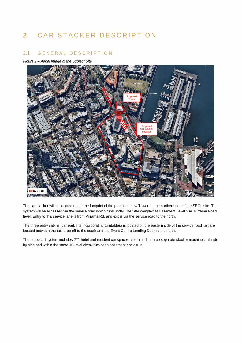
Figure 2 – Aerial Image of the Subject Site
The car stacker will be located under the footprint of the proposed new Tower, at the northern end of the SEGL site. The
system will be accessed via the service road which runs under The Star complex at Basement Level 2 ie. Pirrama Road
level. Entry to this service lane is from Pirrama Rd, and exit is via the service road to the north.
The three entry cabins (car park lifts incorporating turntables) is located on the eastern side of the service road just are
located between the taxi drop off to the south and the Event Centre Loading Dock to the north.
The proposed system includes 221 hotel and resident car spaces, contained in three separate stacker machines, all side
by side and within the same 10-level circa-25m-deep basement enclosure.
2 C A R S T A C K E R D E S C R I P T I O N
Proposed Tower
Proposed Car Stacker
Location
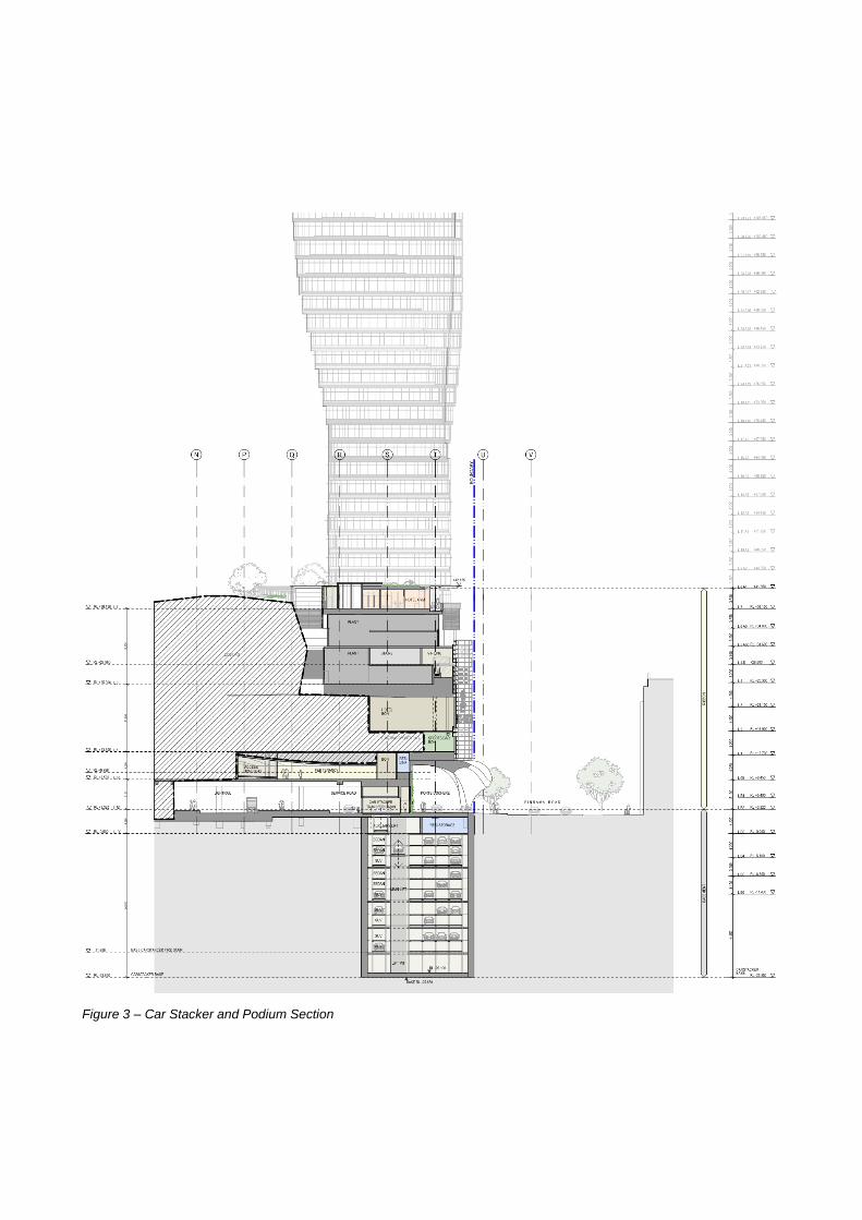
Figure 3 – Car Stacker and Podium Section

Figure 4 – Basement Level 2 – Car Stacker entry cabins and turntables
Figure 5 – Basement Level 3 – Car Stacker transfer level
Figure 6 – Basement Level 5 – Car Stacker typical level
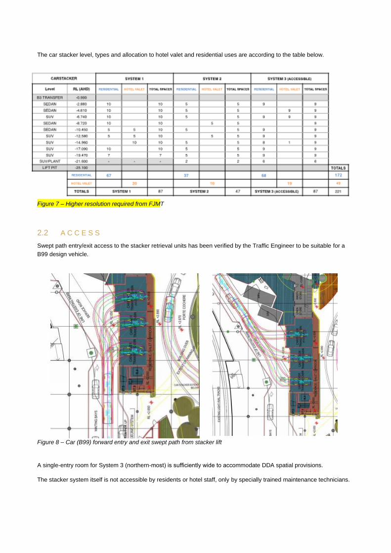
The car stacker level, types and allocation to hotel valet and residential uses are according to the table below.
Figure 7 – Higher resolution required from FJMT
2.2 A C C E S S
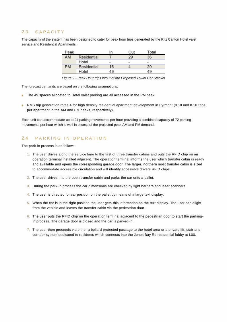
Swept path entry/exit access to the stacker retrieval units has been verified by the Traffic Engineer to be suitable for a
B99 design vehicle.
Figure 8 – Car (B99) forward entry and exit swept path from stacker lift
A single-entry room for System 3 (northern-most) is sufficiently wide to accommodate DDA spatial provisions.
The stacker system itself is not accessible by residents or hotel staff, only by specially trained maintenance technicians.
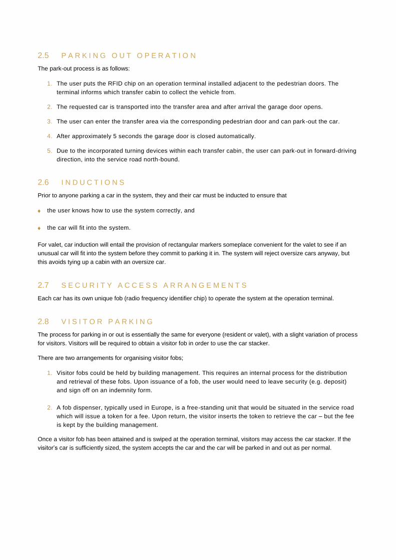
2.3 C A P A C I T Y
The capacity of the system has been designed to cater for peak hour trips generated by the Ritz Carlton Hotel valet
service and Residential Apartments.
Figure 9 - Peak Hour trips in/out of the Proposed Tower Car Stacker
The forecast demands are based on the following assumptions:
The 49 spaces allocated to Hotel valet parking are all accessed in the PM peak.
RMS trip generation rates 4 for high density residential apartment development in Pyrmont (0.18 and 0.10 trips
per apartment in the AM and PM peaks, respectively).
Each unit can accommodate up to 24 parking movements per hour providing a combined capacity of 72 parking
movements per hour which is well in excess of the projected peak AM and PM demand.
2.4 P A R K I N G I N O P E R A T I O N
The park-in process is as follows:
1. The user drives along the service lane to the first of three transfer cabins and puts the RFID chip on an
operation terminal installed adjacent. The operation terminal informs the user which transfer cabin i s ready
and available and opens the corresponding garage door. The larger, northern most transfer cabin is sized
to accommodate accessible circulation and will identify accessible drivers RFID chips.
2. The user drives into the open transfer cabin and parks the car onto a pallet.
3. During the park-in process the car dimensions are checked by light barriers and laser scanners.
4. The user is directed for car position on the pallet by means of a large text display.
5. When the car is in the right position the user gets this information on the text display. The user can alight
from the vehicle and leaves the transfer cabin via the pedestrian door.
6. The user puts the RFID chip on the operation terminal adjacent to the pedestrian door to start the parking-
in process. The garage door is closed and the car is parked-in.
7. The user then proceeds via either a bollard protected passage to the hotel area or a private lift, stair and
corridor system dedicated to residents which connects into the Jones Bay Rd residential lobby at L00.
2.5 P A R K I N G O U T O P E R A T I O N
The park-out process is as follows:
1. The user puts the RFID chip on an operation terminal installed adjacent to the pedestrian doors. The
terminal informs which transfer cabin to collect the vehicle from.
2. The requested car is transported into the transfer area and after arrival the garage door opens.
3. The user can enter the transfer area via the corresponding pedestrian door and can park-out the car.
4. After approximately 5 seconds the garage door is closed automatically.
5. Due to the incorporated turning devices within each transfer cabin, the user can park-out in forward-driving
direction, into the service road north-bound.
2.6 I N D U C T I O N S
Prior to anyone parking a car in the system, they and their car must be inducted to ensure that
the user knows how to use the system correctly, and
the car will fit into the system.
For valet, car induction will entail the provision of rectangular markers someplace convenient for the valet to see if an
unusual car will fit into the system before they commit to parking it in. The system will reject oversize cars anyway, but
this avoids tying up a cabin with an oversize car.
2.7 S E C U R I T Y A C C E S S A R R A N G E M E N T S
Each car has its own unique fob (radio frequency identifier chip) to operate the system at the operation terminal.
2.8 V I S I T O R P A R K I N G
The process for parking in or out is essentially the same for everyone (resident or valet), with a slight variation of process
for visitors. Visitors will be required to obtain a visitor fob in order to use the car stacker.
There are two arrangements for organising visitor fobs;
1. Visitor fobs could be held by building management. This requires an internal process for the distribution
and retrieval of these fobs. Upon issuance of a fob, the user would need to leave security (e.g. deposit)
and sign off on an indemnity form.
2. A fob dispenser, typically used in Europe, is a free-standing unit that would be situated in the service road
which will issue a token for a fee. Upon return, the visitor inserts the token to retrieve the car – but the fee
is kept by the building management.
Once a visitor fob has been attained and is swiped at the operation terminal, visitors may access the car stacker. If the
visitor’s car is sufficiently sized, the system accepts the car and the car will be parked in and out as per normal.
3.1 C O O R D I N A T I O N W I T H T H E B 2 S E R V I C E R O A D A N D L O A D I N G D O C K
The service road is one way and all three car stacker transfer cabins are located before the loading dock. All three
transfer cabins include a turntable so parking cars can indicate and drive straight in to transfer cabins from the service
lane. There is no overlap or conflict between parking cars and loading dock vehicles.
Departing stacker vehicles also drive straight out, and will be required to observe loading dock movements as per any
vehicle presently departing via the service road by the existing loading dock.
3.2 Q U E U I N G
Management of queueing along the service road because of high demand or malfunction of one or more of the car-
stacker retrieval units
There are three independent car stacker systems fed by three independent transfer cabins on B2; one transfer cabin per
stacker system. In the event of a system malfunction, there are still 2 operational systems. For periods outside of peak
parking traffic periods, 2 systems will adequately service demand.
Four “Waiting bays” have been included on the western edge of the Service Road before the transfer cabins in the event
of a system failure during peak parking traffic periods.
3.3 A L T E R N A T E P A R K I N G L O C A T I O N S
As discussed in Section 2.3, the car stacker has high capacity due to its 3 lifts – 3 machine configuration. The likelihood
of extensive queueing in the service road is low. In any case, the Ritz Carlton loading dock manager is the manager of
the logistics of the northern end of the Service road at the Tower zone. He will be authorised to direct any car in the car
stacker queues to temporarily wait at the Star bus lane which is immediately adjacent and south of the car stacker
waiting lane.
A further fall-back position is for the waiting cars to be directed to the Star basement parking.
3.4 M A L F U N C T I O N A N D I N C I D E N T M A N A G E M E N T
The Ritz Carlton loading dock manager has oversight over incidents in the service road and at the retrieval units or
loading bays.
3 O P E R A T I O N A L A N D M A N A G E M E N T
S T R A T E G I E S