modification in freyssinet prestressing system to reduce
TRANSCRIPT

© 2018 JETIR November 2018, Volume 5, Issue 11 www.jetir.org (ISSN-2349-5162)
JETIRK006080 Journal of Emerging Technologies and Innovative Research (JETIR) www.jetir.org 549
Modification in freyssinet prestressing system to
reduce stress concentration Priyank Kadecha
Research scholar, M.Tech in
Structural engineering.
BVM Engineering College.
VVNagar, Gujarat, India
Dr. Vishal A. Arekar
Assistant professor, Structural
engineering.
BVM Engineering College.
VVNagar, Gujarat, India
Prof. Elizabth George
Assosiate professor,Structural
engineering.
BVM Engineering College.
VVNagar, Gujarat, India
Abstract –
Prestressed concrete plays a major role in modern construction. The basic idea behind prestress is to provide counter bending to the
concrete element so that the final bending stress at service could be reduced. Prestressing is the allocation of the stresses to the concrete
element prior to the external loading. The prestressing in reinforced cement concrete is practiced by stretching the high strength steel
and locking it by one or another way, and hence stress is transfered to the concrete. Prestressing can be done in two ways: pre-tensioning
and post tensioning. In the present study,the post tension prestressing has been focused. The post tension is carried out after casting and
hardening of the concrete by elongating the prestressing steel and anchored it at the ends, (with help of hydraulic jack).In this process
the concrete element is subjected to high concentrated stresses at the end. These strsses are directly proportional to the prestressing
force applied to the prestressing steel. This paper describes modified procedurre to reduce the end block stresses in prestressed concrete
element.
Keywords: Post tension, modified prestressing system, end block stress.
I. INTRODUCTION
A prestressed concrete structure is different from a conventional reinforced concrete structure due to the application of an initial
load on the structure prior to its use [1]. Prestressing is carried out by two ways; pretension and post tension [1]. In pretension, steel
is stressed first and then concrete is casted, when the concrete is getting hardened then the steel is cut from the ends.The stress is
transfered mainly through the friction i.e. bond between the steel and concrete.Whereas in post tension the the reinforcement steel
is laid in predefined profile surrounded by a duct and then concrete is casted. When the concrete is hardened then the steel is
stretched with help of hydraulic jack and this stressed steel is anchored at the ends [2]. The stress is transfered directly to the concrete
at the ends. The concentration of the end stresses is very high in post tension member [2].
Recently, many advances are carried out in prestressed concrete technology [4].The high amount of the stresses at the end is due to
the concentration of the high amount of the prestressing force [5],[6]. In this study the modification is done in the existing Freyssinet
prestressing system which is one of available out of twelve to thirteen prestressing systems which are used worldwide. In this study
application of the prestressing force is distributed to achieve distribution of the stress.
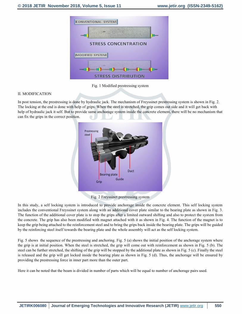
The conceptual idea of how the modification will be carried out can be understood by Fig. 1. In Post tension, anchorage is provided
at the end. If it is managed to provide the same anchorage inside the concrete element then the prestressing force can be distributed
and, hence, there will be the distribution of the stresses.
The focussed stresses are bearing stress and bursting tension developed due to the end anchorages [2].
© 2018 JETIR November 2018, Volume 5, Issue 11 www.jetir.org (ISSN-2349-5162)
JETIRK006080 Journal of Emerging Technologies and Innovative Research (JETIR) www.jetir.org 550
Fig. 1 Modified prestressing system
II. MODIFICATION
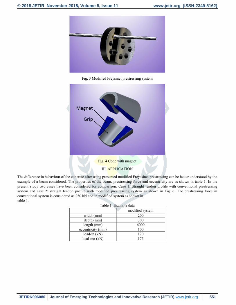
In post tension, the prestressing is done by hydraulic jack. The mechanism of Freyssinet prestressing system is shown in Fig. 2.
The locking at the end is done with help of grips. When the steel is stretched, the grip comes out side and it will get back with
help of hydraulic jack it self. But to provide same anchorage system inside the concrete element, there will be no mechanism that
can fix the grips in the correct position.
Fig. 2 Freyssinet prestressing system
In this study, a self locking system is introduced to provide anchorage inside the concrete element. This self locking system
includes the conventional Freyssinet system along with an additional cover plate similar to the bearing plate as shown in Fig. 3.
The function of the additional cover plate is to stop the grips after a limited outward shifting and also to protect the system from
the concrete. The grip has also been modified with magnet attached with it as shown in Fig. 4. The function of the magnet is to
keep the grip being attached to the reinforcement steel and to bring the grips back inside the bearing plate. The grips will be guided
by the reinforcing steel itself towards the bearing plate and the whole assembly will act as the self locking system.
Fig. 5 shows the sequence of the prestressing and anchoring. Fig. 5 (a) shows the initial position of the anchorage system where
the grip is at initial position. When the steel is stretched, the grip will come out with reinforcement as shown in Fig. 5 (b). The
steel can be further stretched, the shifting of the grip will be stopped by the additional plate as shown in Fig. 5 (c). Finally the steel
is released and the grip will get locked inside the bearing plate as shown in Fig. 5 (d). Thus, the anchorage will be ensured by
providing the prestressing force in inner part more than the outer part.
Here it can be noted that the beam is divided in number of parts which will be equal to number of anchorage pairs used.
© 2018 JETIR November 2018, Volume 5, Issue 11 www.jetir.org (ISSN-2349-5162)
JETIRK006080 Journal of Emerging Technologies and Innovative Research (JETIR) www.jetir.org 551
Fig. 3 Modified Freysinet prestressing system
Fig. 4 Cone with magnet
III. APPLICATION
The difference in behaviour of the concrete after using presented modified Freyssinet prestressing can be better understood by the
example of a beam considered. The properties of the beam, prestressing force and eccentricity are as shown in table 1. In the
present study two cases have been considered for comparison. Case 1: Straight tendon profile with conventional prestressing
system and case 2: straight tendon profile with modified prestressing system as shown in Fig. 6. The prestressing force in
conventional system is considered as 250 kN and in modified system as shown in table 1.
Table 1: Example data
modified system
width (mm) 200 depth (mm) 300 length (mm) 6000
eccentricity (mm) 100 load-in (kN) 120
load-out (kN) 175

© 2018 JETIR November 2018, Volume 5, Issue 11 www.jetir.org (ISSN-2349-5162)
JETIRK006080 Journal of Emerging Technologies and Innovative Research (JETIR) www.jetir.org 552
(a) Initial position of grip (b) Grip gets out with steel (c) Further stretching of steel (d) Locking after releasing the steel
Fig. 5 Modified prestressing
The deflection of the beam is taken as the base of the comparison. The formulae used for the deflection of the beam are as shown
in Fig. 7. In that P=prestressing force,e=inner eccentricity, EI=flexural rigidity of the concrete(standard prestressed concrete).
IV. RESULTS
When compared to the conventional prestressing system it is found that the same deflcetion with the same external load can not
be obtained because it depends on the square of the length between two anchorages. To get same deflection either prestressing
force or eccentricity must be increased.In the proposed example the force is increased as shown in Table 1 and eccentricity is kept
with minimum total load in inner part with same deflection,as shown in Table 1.
Table 2 shows the difference in bending stresses, Table 3 shows the difference in bursting tension with straight tendon profile in
conventional prestressing system and modified system. Negative sign indicates reduction.
The bending stress is calculated by below formula:
stress = 𝑃𝐴
+ 𝑃𝑒𝑍
The bursting force is calculated by below formula:
(a) IS code method Fbst
Fbst = Pk [ 0.32 − 0.3 𝑌𝑝𝑜
𝑌𝑜 ]
(b) Zeilinski-Rowe method
Fbst = Pk [ 0.48 − 0.4 𝑌𝑝𝑜
𝑌𝑜 ]
Table 2 : Bending stress
Straight Modified Difference
Straight
Stress-Out 10.41
5 - 51.9 %
Stress-In 22.05 52.8 %
Comp Stress-In 4.16
7.35 76.7 %
Comp Stress-Out 3.18 - 23.5 %
© 2018 JETIR November 2018, Volume 5, Issue 11 www.jetir.org (ISSN-2349-5162)
JETIRK006080 Journal of Emerging Technologies and Innovative Research (JETIR) www.jetir.org 553
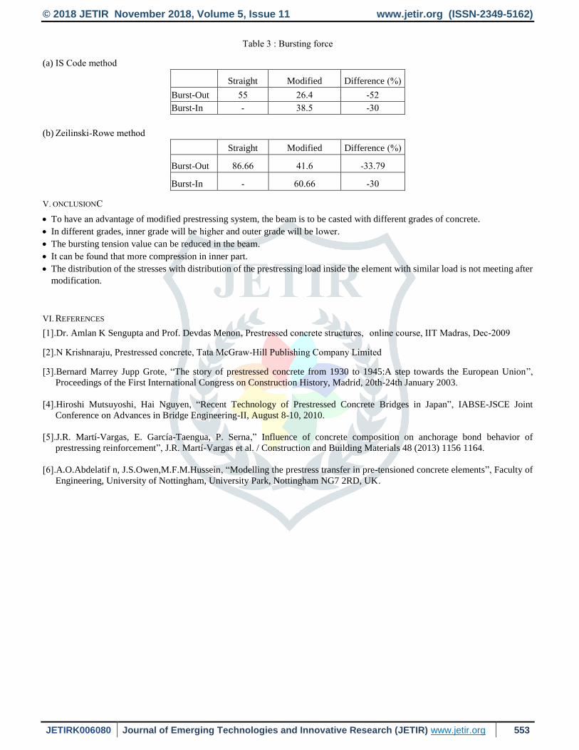
Table 3 : Bursting force
(a) IS Code method
Straight Modified Difference (%)
Burst-Out 55 26.4 -52
Burst-In - 38.5 -30
(b) Zeilinski-Rowe method
Straight Modified Difference (%)
Burst-Out 86.66 41.6 -33.79
Burst-In - 60.66 -30
V. CONCLUSION
To have an advantage of modified prestressing system, the beam is to be casted with different grades of concrete.
In different grades, inner grade will be higher and outer grade will be lower.
The bursting tension value can be reduced in the beam.
It can be found that more compression in inner part.
The distribution of the stresses with distribution of the prestressing load inside the element with similar load is not meeting after
modification.
VI. REFERENCES
[1].Dr. Amlan K Sengupta and Prof. Devdas Menon, Prestressed concrete structures, online course, IIT Madras, Dec-2009
[2].N Krishnaraju, Prestressed concrete, Tata McGraw-Hill Publishing Company Limited
[3].Bernard Marrey Jupp Grote, “The story of prestressed concrete from 1930 to 1945:A step towards the European Union”,
Proceedings of the First International Congress on Construction History, Madrid, 20th-24th January 2003.
[4].Hiroshi Mutsuyoshi, Hai Nguyen, “Recent Technology of Prestressed Concrete Bridges in Japan”, IABSE-JSCE Joint
Conference on Advances in Bridge Engineering-II, August 8-10, 2010.
[5].J.R. Martí-Vargas, E. García-Taengua, P. Serna,” Influence of concrete composition on anchorage bond behavior of
prestressing reinforcement”, J.R. Martí-Vargas et al. / Construction and Building Materials 48 (2013) 1156 1164.
[6].A.O.Abdelatif n, J.S.Owen,M.F.M.Hussein, “Modelling the prestress transfer in pre-tensioned concrete elements”, Faculty of
Engineering, University of Nottingham, University Park, Nottingham NG7 2RD, UK.