modified midwest guardrail system (mmgs)...sep 04, 2018 · modified midwest guardrail system...
TRANSCRIPT

Modified Midwest Guardrail System (MMGS)
M30 P1 Passive Barrier System
This guardrail system is intended to provide a cost-effective means for establishing passive barriers on military installations. The MMGS design is based on five primary principles:
Give consideration to occupant safety.
Meet ASTM F2656-15 M30 P1 criteria.
Exist as a non-proprietary design that is not owned or patented.
Utilize “standard hardware” which is defined as readily-available, off-the-shelf, and/or prefabricated structural sections.
Reduce costs for DOD installations. Based on a 1.0 area cost adjustment factor, system costs are
estimated at $15,700 for two anchor sections plus $61 per linear foot for the guardrail run. The MMGS is based off the Midwest Guardrail System design, with the following modifications:
Replaces the 10-gauge thrie beam with nested 12-gauge thrie beam (i.e., 2x rails per rail segment). The increased number of plies of rail will resist splice bolt pullout, increase total cross-sectional area of the rail (and thus rail tensile capacity at splices and non-splices), and reduce bearing failure at splices. NOTE: At rail splices, maintain rail nesting such that two outer plies overlap both two inner plies. At post locations, bolt through both plies of rail. At the end anchorages, place both plies of thrie beam between the outer and inner thrie end connectors.
Substitutes the standard-grade, 5/8” diameter guardrail bolts at splices for ASTM F3125 or A449, 5/8” diameter, heavy hex head bolts and nuts and ASTM F844 washers on both sides of the rail.
Reduces the soil embedment depth by 6 inches to 45 inches.
This guardrail system was approved on 01 May 2018 by the USACE - Protective Design Center for use as a passive barrier on DOD installations. SDDCTEA requests that installations email construction costs for the MMGS as projects get awarded. EMAIL: [email protected]

12/8/2017
DATE:
1 of 16
SHEET
System Layout Overview
180 DEGREES.
OF THE COMPONENTS BEING ROTATED
DESIGNS ARE IDENTICAL WITH THE EXCEPTION
ARE FOR REFERENCING ONLY. THE ANCHOR
THE TERMS UPSTREAM AND DOWNSTREAM
Note: (1) The impact location is the vehicle centerline impacting at the midspan
between post nos. 15 and 16.
(2) Impact tolerance is +/- 1 ft [305] of nominal location.
(3) Simple splicing used according to normal traffic conventions; no sandwiching
within system. At thrie terminal connection splices, the nested thrie beam was
sandwiched between terminal connectors.
96638"
a1
Nested
a1
Nested
a1
Nested
a1
Nested
a1
Nested
a1
Nested
a1
Nested
a1
Nested
a1
Nested
a1
Nested
a1
Nested
a1
Nested
a1
Nested
442014’-6"
3048120"
442014’-6"
129551"
a3
Nested
ELEVATION VIEW
2-a22-a2
AASHTO M147-65 Grading B Strong Soil
A
A
90°
(TYP)
190575"
95337 1/2"
18296’-0"
61024"
335311’-0"
61024"
54115177’-6 1/2"
52591172’-6 1/2"
PLAN VIEW
1 2 3 4 5 6 7 8 9 10 11 12 13 14 15 16 17 18 19 20 21 22 23 24 25 26 27 28
AASHTO M147-65 Grading B Strong Soil
29
Vehicle Impact
Anchor
DownstreamUpstream Anchor
Transportation Engineering Agency
Distribution Command
and
Military Surface Deployment
Guardrail System
Modified Midwest
UNITS:
in[mm]
Rating: M30 P1

12/8/2017
DATE:
Post and Splice Details
2 of 16
SHEET
75 [1905]
Ground
Line
SPLICE DETAIL
BACKSIDE
Post No. 16 Post No. 15
Note: (1) Guardrail bolts (part f5) on the upstream side of the
web.
(2) A drift pin may be used to attach nested rails. If
galvanization is damaged, galvanizing spray may be used
to ensure proper rust protection.
(3) Washers (part f7) used on front and back of splice
bolts.
B
f6
39 [991]
45 [1143]
38 [966]
SECTION A-A
e2
f5
e1
Ground
Line
a1
Nested
DETAIL B
f7
f5
Transportation Engineering Agency
Distribution Command
and
Military Surface Deployment
Guardrail System
Modified Midwest
UNITS:
in[mm]
Rating: M30 P1
12/8/2017
DATE:
3 of 16
SHEET
Anchorage Overview
ARE FOR REFERENCING ONLY (SEE SHEET 1).
THE TERMS UPSTREAM AND DOWNSTREAM
COMPONENTS BEING ROTATED 180 DEGREES.
DESIGN WITH THE EXCEPTION OF THE
DOWNSTREAM ANCHOR IS THE SAME
ANCHOR AS THE EXAMPLE. THE
THIS DRAWING SHOWS THE UPSTREAM
Notes: (1) Two thrie terminal connectors (part a2) needed per end anchorage.
(2) A drift pin may be used to attach nested rails. If galvanization is
damaged, galvanizing spray may be used to ensure proper rust protection.
37 1/2 [953] 76 1/4 [1937]
6 [152]
Ground
Line
ELEVATION VIEW
Anchor Post
Assembly Support Post
Assembly
2-a2
a1
f4
Post No. 3
See Note 1
Nested
C
27 [686]
38 [966]
PROFILE VIEW
f6
2-a2
Support Post
Assembly
f4
f8
f8
Concrete Anchor Assembly
Concrete Anchor Assembly
Transportation Engineering Agency
Distribution Command
and
Military Surface Deployment
Guardrail System
Modified Midwest
UNITS:
in[mm]
Rating: M30 P1
12/8/2017
DATE:
4 of 16
SHEET
Detail C
Anchor Attachment Note: (1) Threaded rods (Part f1) anchored to concrete anchorage using
Powers Fasteners AC100+ Gold epoxy or an equivalent epoxy with a
minimum bond strength of 1,305 psi [9.0 MPa].
8 [203] 8 [203]
5 [127] 5 [127]
16 [407] 8 [203] 7 3/4 [197]
9 [229]
DETAIL C
f1
f2
f3
20 1/4 [514]
Transportation Engineering Agency
Distribution Command
and
Military Surface Deployment
Guardrail System
Modified Midwest
UNITS:
in[mm]
Rating: M30 P1

12/8/2017
DATE:
5 of 16
SHEET
Concrete Anchor Details
Upstream Anchor
=96 [2438]
@ 6"[152]
16 Spaces
14 3/4 [375]
6 3/16 [157]
102 [2591]
18 [457]
ELEVATION VIEW
b5
b4
14 3/4 [375]
6 3/16 [157]
78 [1981]
Ø36 [Ø914]
PLAN VIEW
b4
b5
b6
b1
(TYP)
12 [305]
54 [1372]
PROFILE VIEW
b6
b3
b2
b1
b4
b5
(TYP)
CLR
2 [51]
10 1/2 [266]
(TYP)
1 1/2 [38]
CLR
CLR (TYP)
2 [51]
5 [127]
(TYP)
CLR
2 [51]
(TYP)
10 1/2 [266]
CLR (TYP)
2 [51]
2 1/2 [64]
CLR
Note: (1) Anchor is rotated 180 for downstream configuration.
Transportation Engineering Agency
Distribution Command
and
Military Surface Deployment
Guardrail System
Modified Midwest
UNITS:
in[mm]
Rating: M30 P1
12/8/2017
DATE:
6 of 16
SHEET
Concrete Anchor Details
Downstream Anchor
CLR (TYP)
2 [51]
14 3/4 [375]
6 3/16 [157]
=96 [2438]
@ 6"[152]
16 Spaces
102 [2591]
18 [457]
ELEVATION VIEW
b5
b4
78 [1981]
14 3/4 [375]
6 3/16 [157]
Ø36 [Ø914]
PLAN VIEW
b4
b5b6
b1
54 [1372]
(TYP)
12 [305]
PROFILE VIEW
b6
b3
b2
b1
b4
b5
2 [51]
CLR
(TYP)
10 1/2 [266]
(TYP)
2 [51]
CLR (TYP)
5 [127]
(TYP)
1 1/2 [38]
CLR
10 1/2 [266]
(TYP)
2 1/2 [64]
CLR
Note: (1) Anchor is rotated 180 for upstream configuration.
Transportation Engineering Agency
Distribution Command
and
Military Surface Deployment
Guardrail System
Modified Midwest
UNITS:
in[mm]
Rating: M30 P1

12/8/2017
DATE:
7 of 16
SHEET
Rebar Details
Concrete Anchor
Bill of Bars
ITEM NO. QTY BAR SIZE UNBENT LENGTH MATERIAL SPEC
b3 32 #8 [25] 114" [2,896] ASTM A615 Gr. 60
b4 16 #5 [16] 140 3/4" [3,575] ASTM A615 Gr. 60
b5 24 #5 [16] 74" [1,880] ASTM A615 Gr. 60
b6 34 #4 [13] 122" [3,099] ASTM A615 Gr. 60
LAP
18"[457]
Ø32 [Ø813]
Bar b6
114 [2896]
Bar b3
(TYP)
Ø2 1/2 [Ø64]
50 [1270]
14 [356]
LAP
18 [457]
Bar b4
74 [1880]
Bar b5
Transportation Engineering Agency
Distribution Command
and
Military Surface Deployment
Guardrail System
Modified Midwest
UNITS:
in[mm]
Rating: M30 P1
12/8/2017
DATE:
8 of 16
SHEET
Anchor Post Assembly
55°1 [25]
1 [25]
1/4 [6]
c2
c1
c5
ELEVATION VIEW
Weep Hole on Front
and Back Faces
c4c3
Weep Hole on Front
and Back Faces
1/4"[6]E70xx
5/16"[8]E70xx
1/4"E70xx
4 [102]
4 [102]4 [102]
4 [102]
c4
c3
PLAN VIEW
c1
c5
c2
1/4"[6]E70xx
5/16"[8]E70xx
1/4"E70xx
3/4 [19]
3/4 [19]
1/4 [6]1/4 [6]
PROFILE VIEW
c5
c2
c1
4 5/16 [110]
4 5/16 [110]
1/4 [6]
Transportation Engineering Agency
Distribution Command
and
Military Surface Deployment
Guardrail System
Modified Midwest
UNITS:
in[mm]
Rating: M30 P1

12/8/2017
DATE:
9 of 16
SHEET
Anchor Post Components
[356]
14
[241]
9 1/2
[76]
3
[203]
8
(TYP)
[Ø29]
Ø1 1/8
PLAN VIEW
[292]
11 1/2
[140]
5 1/2
PROFILE VIEW
[356]
14
ELEVATION VIEW
Part c3
[305]
12
[76]
3 [127]
5
[57]
2 1/4
[191]
7 1/2
[127]
5
(TYP)
[Ø29]
Ø1 1/8
PLAN VIEW
[406]
16
ELEVATION VIEW
Part c4
[13]
1/2
ELEVATION VIEW
Part c5
[978]
38 1/2
[84]
3 5/16
[51]
2 [102]
4
[194]
7 5/8
[194]
7 5/8 [194]
7 5/8
[152]
6
(TYP)
[Ø25]
Ø1
[102]
4
[181]
7 1/8
ELEVATION VIEW
Part c1
[152]
6
[305]
12
[6]
1/4
PLAN VIEW
55°
[1168]
46
35°
[218]
8 9/16
[76]
3
ELEVATION VIEW
Part c2
[102]
4
[152]
6
[8]
5/16
PLAN VIEW
Weep Hole
R5/16
33 1/4 [844]
4 3/16 [107]
2 1/8 [53]
Weep Hole
R5/16 [8]
1/2 [13]1/2 [13]
2 1/4 [57]
Transportation Engineering Agency
Distribution Command
and
Military Surface Deployment
Guardrail System
Modified Midwest
UNITS:
in[mm]
Rating: M30 P1

12/8/2017
DATE:
10 of 16
SHEET
Post Assembly
Anchor Support
60°
ELEVATION VIEW
d1
d3
d2
d4
Thru Weep Hole
[152]
6
[178]
7
[178]
7
PLAN VIEW
d4
d3
d1d2
PROFILE VIEW
d2
d11/4 [6]
1 7/8 [48]
1/4 [6]
3 3/4 [94]
3 7/8 [99] 1 7/8 [48]
1/4 [6]
1/4 [6]
1/4 [6]
Transportation Engineering Agency
Distribution Command
and
Military Surface Deployment
Guardrail System
Modified Midwest
UNITS:
in[mm]
Rating: M30 P1
12/8/2017
DATE:
11 of 16
SHEET
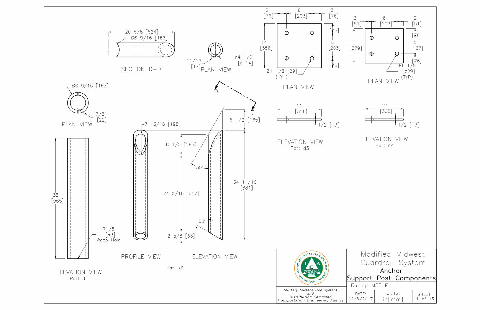
Support Post Components
Anchor
[356]
14
ELEVATION VIEW
Part d3
[356]
14
[76]
3
[203]
8
[76]
3
[76]
3
[203]
8
[76]
3
PLAN VIEW
[305]
12
ELEVATION VIEW
Part d4
[279]
11
[51]
2
[203]
8
[51]
2
[76]
3
[127]
5
[76]
3
(TYP)
[Ø29]
Ø1 1/8
PLAN VIEW
Weep Hole
[R3]
R1/8
[965]
38
ELEVATION VIEW
Part d1
[22]
7/8
PLAN VIEW
30°
[881]
34 11/16
60°
ELEVATION VIEW
D
D
SECTION D-D
[Ø114]
Ø4 1/2
[17]
11/16
PLAN VIEW
PROFILE VIEW
Part d2
Ø6 9/16 [167]
20 5/8 [524]
Ø6 9/16 [167]
(TYP)
Ø1 1/8 [29]
1/2 [13]1/2 [13]
6 1/2 [165]7 13/16 [198]
6 1/2 [165]
24 5/16 [617]
2 5/8 [66]
Transportation Engineering Agency
Distribution Command
and
Military Surface Deployment
Guardrail System
Modified Midwest
UNITS:
in[mm]
Rating: M30 P1

12/8/2017
DATE:
12 of 16
SHEET
Post Nos. 3 thru 26
[181]
7 1/8
[19]
3/4
ELEVATION VIEWPart e1
[100]
3 15/16
PLAN VIEW
[2134]
84
PROFILE VIEW
[152]
6
[44]
1 3/4
[181]
7 1/8
ELEVATION VIEW
[114]
4 1/2
[19]
3/4
PLAN VIEW
[559]
22
[203]
8
PROFILE VIEW
Ø3/4 [19]
5 7/8 [150]
Ø3/4 [19]
3/8 [10]
Part e2
Transportation Engineering Agency
Distribution Command
and
Military Surface Deployment
Guardrail System
Modified Midwest
UNITS:
in[mm]
Rating: M30 P1

12/8/2017
DATE:
13 of 16
SHEET
Rail Details
Note: (1) A drift pin may be used to attach nested rails. If galvanization is damaged,
galvanizing spray may be used to ensure propper rust protection.
[1111]
43 3/4
[159]
6 1/4
ELEVATION VIEW
Part a1
F
[216]
8 1/2
[51]
2
[159]
6 1/4
PROFILE VIEW
[76]
3
[216]
8 1/2
[762]
30
(TYP)
[R25]
R1
[507]
20
[51]
2
[102]
4
[102]
4E
E
10-gauge[3.4]
(TYP)
[952]
37 1/2 [2223]
87 1/2
ELEVATION VIEW
Part a3 PROFILE VIEW
162 1/2 [4128]
[19x64] Slot (TYP)
2 3/8 [60]
3 13/16 [97]
3 13/16 [97]
3 13/16 [97]
3 13/16 [97]
Ø3/4 [19]
(TYP)
[19x64] Slot
7 1/4 [184]
[19]
Ø3/4
(TYP)
[22x44] Slot
(TYP)
Ø1 [25]
(TYP)
3/4 x2 1/2
[19x64] Slot
12-gauge[2.7]
(TYP)
37 1/2 [953]
12-gauge[2.7]
DETAIL FSECTION E-E
ELEVATION VIEW
Part a2
Transportation Engineering Agency
Distribution Command
and
Military Surface Deployment
Guardrail System
Modified Midwest
UNITS:
in[mm]
Rating: M30 P1

12/8/2017
DATE:
14 of 16
SHEET
Hardware
[254]
10
[102]
4
Part f5
[279]
11
Part f1
[25]
1
Part f2
[203]
8
[57]
2 1/4
Part f4
Part f3
Part f8
[3]
1/8
[44]
1 3/4
[32]
1 1/4
Part f6
Part f7
5/8-11 UNC
1-8 UNC
7/8-9 UNC
5/8-11 UNC
5/8 [16]
1/8 [3]Ø1 3/4 [44]
Ø11/16 [17]
Ø1 3/4 [44]
Ø15/16 [24]
9/16 [14]
7/8 [22]
3/16 [4]Ø2 [51]
Ø1 1/16 [27]
Transportation Engineering Agency
Distribution Command
and
Military Surface Deployment
Guardrail System
Modified Midwest
UNITS:
in[mm]
Rating: M30 P1

12/8/2017
DATE:
15 of 16
SHEET
Bill of Materials
* Galvanize after welding
ItemNo.
QTY. Description Material Specification Treatment SpecificationHardware
Guide
a1 26 12’-6" [3,810] 12-gauge [2.7] Thrie BeamSection, Half Post Spacing
AASHTO M180 ASTM A123 or A653-
a2 4 10-gauge [3.4] Thrie Beam Terminal Connector
AASHTO M180Min. tensile strength = 70 ksi
[482.6 Mpa]
ASTM A123 or A653 RTE01b
a3 2 6’-3" [1,905] 12-gauge [2.7] Thrie BeamSection, Half Post Spacing
AASHTO M180 ASTM A123 or A653-
b1 2 78"x54"x18" [1,981x1,372x457] ReinforcedConcrete Anchor Block Min. f’c = 4,000 psi [27.6 MPa]
- -
b2 2 36" [914] Dia. Concrete Anchor, 102" [2,591]Long Min. f’c = 4,000 psi [27.6 MPa]
- -
b3 32 #8 [25] Straight Rebar, 114" [2,896] Long ASTM A615 Gr. 60 Epoxy Coated (ASTM A775 or A934)-
b4 16 #5 [16] Anchorage Stirrup, 140 3/4" [3,575]Long Unbent
ASTM A615 Gr. 60 Epoxy Coated (ASTM A775 or A934)-
b5 24 #5 [16] Straight Rebar, 74" [1,880] Long ASTM A615 Gr. 60 Epoxy Coated (ASTM A775 or A934)-
b6 34 #4 [13] Anchor Hoop Rebar with 32" [813] Dia.,122" [3,099] Long Unbent
ASTM A615 Gr. 60 Epoxy Coated (ASTM A775 or A934)-
c1 2 HSS 6"x12"x1/4" [152x305x6] Tube, 38 1/2"[978] Long
ASTM A500 Gr. B ASTM A123*-
c2 2 HSS 6"x4"x5/16" [152x102x8] Tube, 46" [1,168]Long
ASTM A500 Gr. B ASTM A123*-
c3 2 14"x14"x1/2" [356x356x13] Steel Plate ASTM A36 or A572 Gr. 50 ASTM A123*-
c4 2 16"x12"x1/2" [406x305x13] Steel Plate ASTM A36 or A572 Gr. 50 ASTM A123*-
c5 2 11 1/2"x5 1/2"x1/2" [292x140x13] Steel Plate ASTM A36 or A572 Gr. 50 ASTM A123*-
d1 2 Pipe 6 [152] xx-Stong Pipe, 38" [965] Long ASTM A53 Gr. B ASTM A123*-
d2 2 Pipe 4 [102] xx-Stong Pipe, 34 11/16" [881]Long
ASTM A53 Gr. B ASTM A123*-
d3 2 14"x14"x1/2" [356x356x13] Steel Plate ASTM A36 or A572 Gr. 50 ASTM A123*-
d4 2 12"x11"x1/2" [305x279x13] Steel Plate ASTM A36 or A572 Gr. 50 ASTM A123*-
e1 25 W6x9 [W152x13.4], 84" [2,134] Long Steel Post ASTM A992 ASTM A123-
e2 25 6"x8"x22" [152x203x559] Timber Blockout SYP Grade No. 1 or better- -
Transportation Engineering Agency
Distribution Command
and
Military Surface Deployment
Guardrail System
Modified Midwest
UNITS:
in[mm]
Rating: M30 P1

12/8/2017
DATE:
16 of 16
SHEET
Bill of Materials
ItemNo.
QTY. Description Material Specification Treatment SpecificationHardware
Guide
f1 36 1" [25] Dia. UNC, 11" [279] Long Threaded RodASTM A449 or A354 Gr. BC or A193
Gr. B7ASTM A153 or B633 or B695 Class 55 or
F1941 or F2329FRR24b
f2 36 1" [25] Dia. Heavy Hex Nut ASTM A563DH or A194 Gr. 2HASTM A153 or B633 or B695 Class 55 or
F1941 or F2329FNX24b
f3 36 1" [25] Dia. Hardened Flat Washer ASTM F436ASTM A153 or B695 Class 55 or F1136
Gr. 3 or F2329FWC24b
f4 14 7/8" [22] Dia., 8" [203] Long Heavy Hex HeadBolt
Bolt - ASTM F3125 Gr. A325 Type 1Nut - ASTM A563DH
ASTM A153 or B695 Class 55 or F1136Gr. 3 or F2329 or F2833 Gr. 1
FBX22b
f5 25 5/8" [16] Dia. UNC, 10" [254] Long GuardrailBolt and Nut
Bolt - ASTM A307 Gr. ANut - ASTM A563A
ASTM A153 or B695 Class 55 or F2329 FBB03
f6 180 5/8" [16] Dia. UNC, 1 3/4" [44] Long HeavyHex Bolt and Nut
Bolt - ASTM F3125 Gr. A325 Type 1Nut - ASTM A563DH
ASTM A153 or B695 Class 55 or F1136Gr. 3 or F2329 or F2833 Gr. 1
FBX16b
f7 360 5/8" [16] Dia. Plain Round Washer ASTM F844 ASTM A123 or A153 or F2329 FWC16a
f8 14 7/8" [22] Dia. Hardened Flat Washer ASTM F436ASTM A153 or B695 Class 55 or F1136
Gr. 3 or F2329FWC22b
- -Epoxy Adhesive Min. Bond Strength = 1,305 psi [9.0
MPa]
- -
Transportation Engineering Agency
Distribution Command
and
Military Surface Deployment
Guardrail System
Modified Midwest
UNITS:
in[mm]
Rating: M30 P1