modified mono multi moulder - mono equip manuals/fg129 12 inch... · operating and maintenance...
TRANSCRIPT

FG129- 12”MOULDER 03-04-17 Rev A17 1
OPERATING AND MAINTENANCE MANUAL
MONO MULTI MOULDER
Enter Serial No. here._____________________________________
In the event of an enquiry please quote this serial number.
www.monoequip.com
FG129- 12”MOULDER 03-04-17 Rev A17 2
FG129- 12”MOULDER 03-04-17 Rev A17 3
MODIFIED MONO MULTI MOULDER
Current MONO Multi Moulders are fitted with an additional safety interlock on the top cleaning cover. The moulder will not start unless this guard is properly located and the safety interlock is correctly engaged. An additional emergency stop button has been fitted at the front of the machine. If the emergency stop button is used the moulder will not restart until the stop button is released by pushing and turning.
IMPORTANT
FG129- 12”MOULDER 03-04-17 Rev A17 4
INDEX
1.0 Introduction 2.0 Dimensions 3.0 Specifications 4.0 Safety 5.0 Installation 6.0 Isolation 7.0 Cleaning Instructions 8.0 Operating conditions 9.0 General remarks – machine moulding of dough 10.0 OPERATING INSTRUCTIONS
Primary adjustments Sheeting gap Moulding pressure Starting 11.0 Maintenance 12.0 MOULDER WILL NOT START 13.0 Service 14.0 Spares 15.0 Electrical diagrams
FG129- 12”MOULDER 03-04-17 Rev A17 5
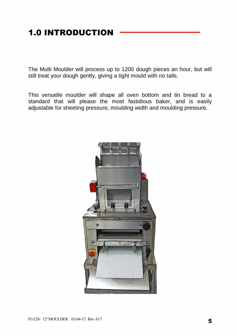
1.0 INTRODUCTION
The Multi Moulder will process up to 1200 dough pieces an hour, but will still treat your dough gently, giving a tight mould with no tails. This versatile moulder will shape all oven bottom and tin bread to a standard that will please the most fastidious baker, and is easily adjustable for sheeting pressure, moulding width and moulding pressure.
FG129- 12”MOULDER 03-04-17 Rev A17 6
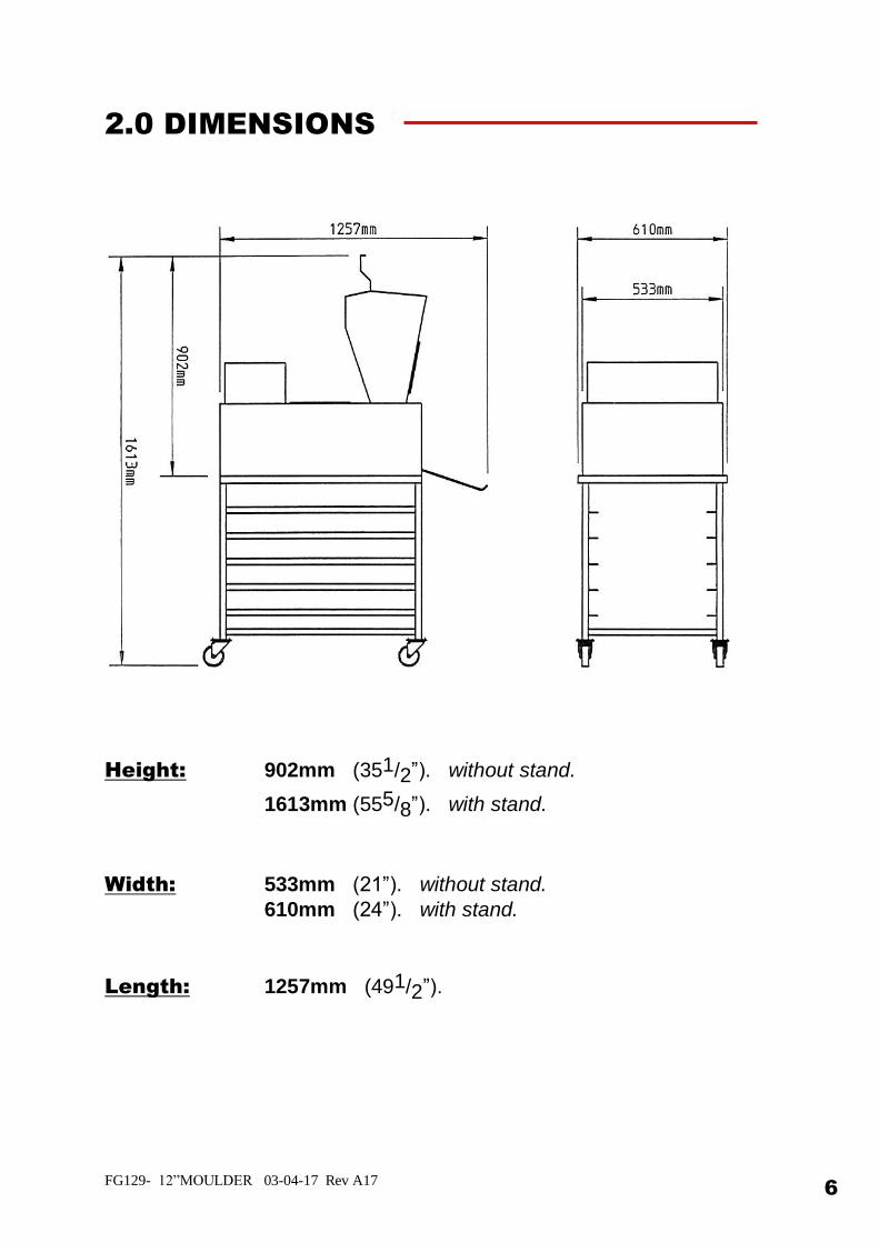
2.0 DIMENSIONS
Height: 902mm (351/2”). without stand.
1613mm (555/8”). with stand.
Width: 533mm (21”). without stand.
610mm (24”). with stand.
Length: 1257mm (491/2”).
FG129- 12”MOULDER 03-04-17 Rev A17 7
3.0 SPECIFICATIONS
Electric: 380v / 415v ,3 phase ,neutral and earth,50/60 Hz
1.7 Amps per phase , 0.55kW.
OR
230v/240v , 1 phase/ 50 Hz 4 Amps / 0.75kW.
Weight: 170kg (375lb).
Noise Level: Less Than 85 dB.
Output: up to 1200 dough pieces an hour
FG129- 12”MOULDER 03-04-17 Rev A17 8
4.0 SAFETY
1 Never use a machine in a faulty condition and always report any damage.
2 No-one under the age of 16 may operate this machine. 3 No-one under the age of 18 may clean this machine under any circumstances.
4 Only trained personnel may remove any part from this machine that
requires a tool to do so. 5 Always ensure hands are dry before touching any electrical appliance (including cable, switch and plug). 6 All operatives must be fully trained. 7 People undergoing training on the machine must be under direct supervision.
8 Do not operate the machine with any panels removed.
9 All guards must be fixed in place with bolts or screws unless protected by a safety switch.
10 No loose clothing or jewellery to be worn while operating the machine.
11 Switch off power at the mains isolator when machine is not in use and before carrying out any cleaning or maintenance. ALL CLEANING AND MAINTENANCE OPERATIONS MUST BE MADE WITH MACHINE DISCONNECTED FROM THE POWER SUPPLY
12 The Bakery Manager or the Bakery Supervisor must carry out daily safety
checks on the machine.
FG129- 12”MOULDER 03-04-17 Rev A17 9
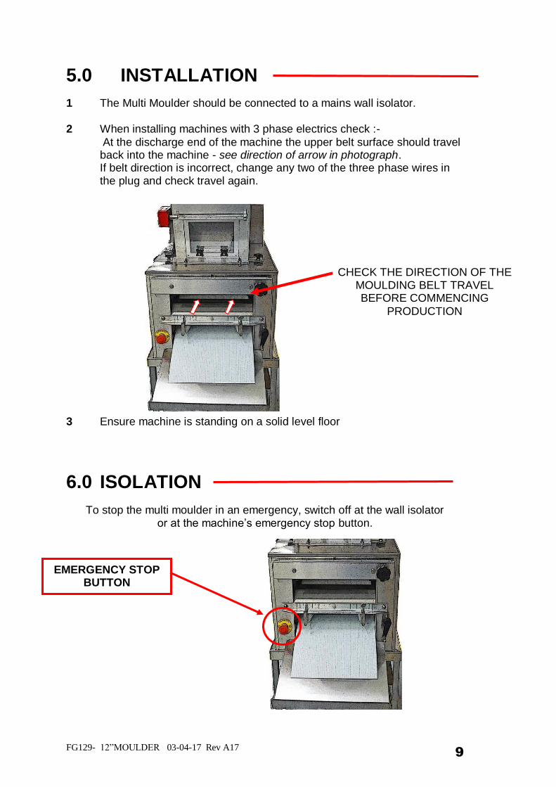
5.0 INSTALLATION
1 The Multi Moulder should be connected to a mains wall isolator.
2 When installing machines with 3 phase electrics check :-
At the discharge end of the machine the upper belt surface should travel back into the machine - see direction of arrow in photograph. If belt direction is incorrect, change any two of the three phase wires in the plug and check travel again.
3 Ensure machine is standing on a solid level floor
6.0 ISOLATION
To stop the multi moulder in an emergency, switch off at the wall isolator or at the machine’s emergency stop button.
EMERGENCY STOP BUTTON
CHECK THE DIRECTION OF THE MOULDING BELT TRAVEL BEFORE COMMENCING
PRODUCTION
FG129- 12”MOULDER 03-04-17 Rev A17 10
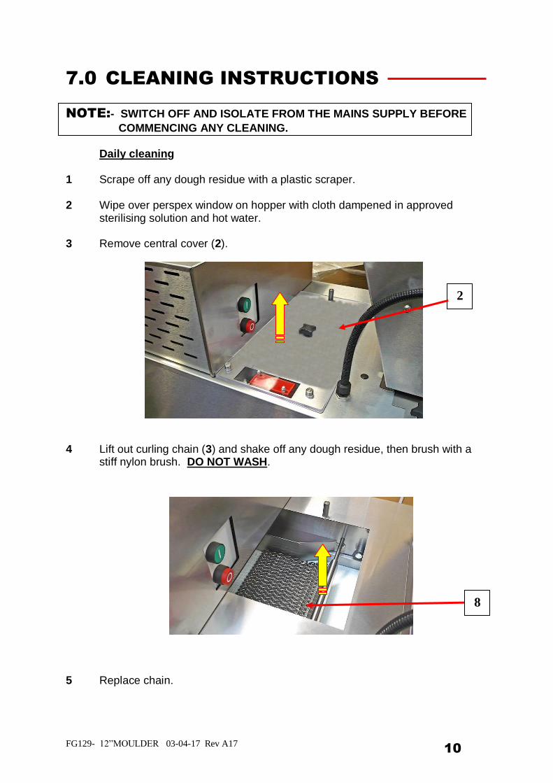
7.0 CLEANING INSTRUCTIONS
NOTE:- SWITCH OFF AND ISOLATE FROM THE MAINS SUPPLY BEFORE
COMMENCING ANY CLEANING. Daily cleaning 1 Scrape off any dough residue with a plastic scraper. 2 Wipe over perspex window on hopper with cloth dampened in approved sterilising solution and hot water. 3 Remove central cover (2).
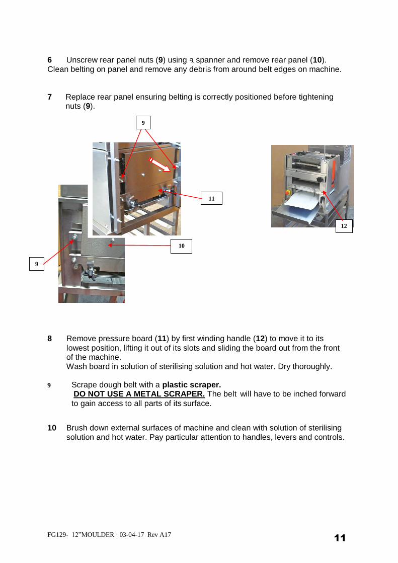
4 Lift out curling chain (3) and shake off any dough residue, then brush with a
stiff nylon brush. DO NOT WASH.
5 Replace chain.
2
8
FG129- 12”MOULDER 03-04-17 Rev A17 11
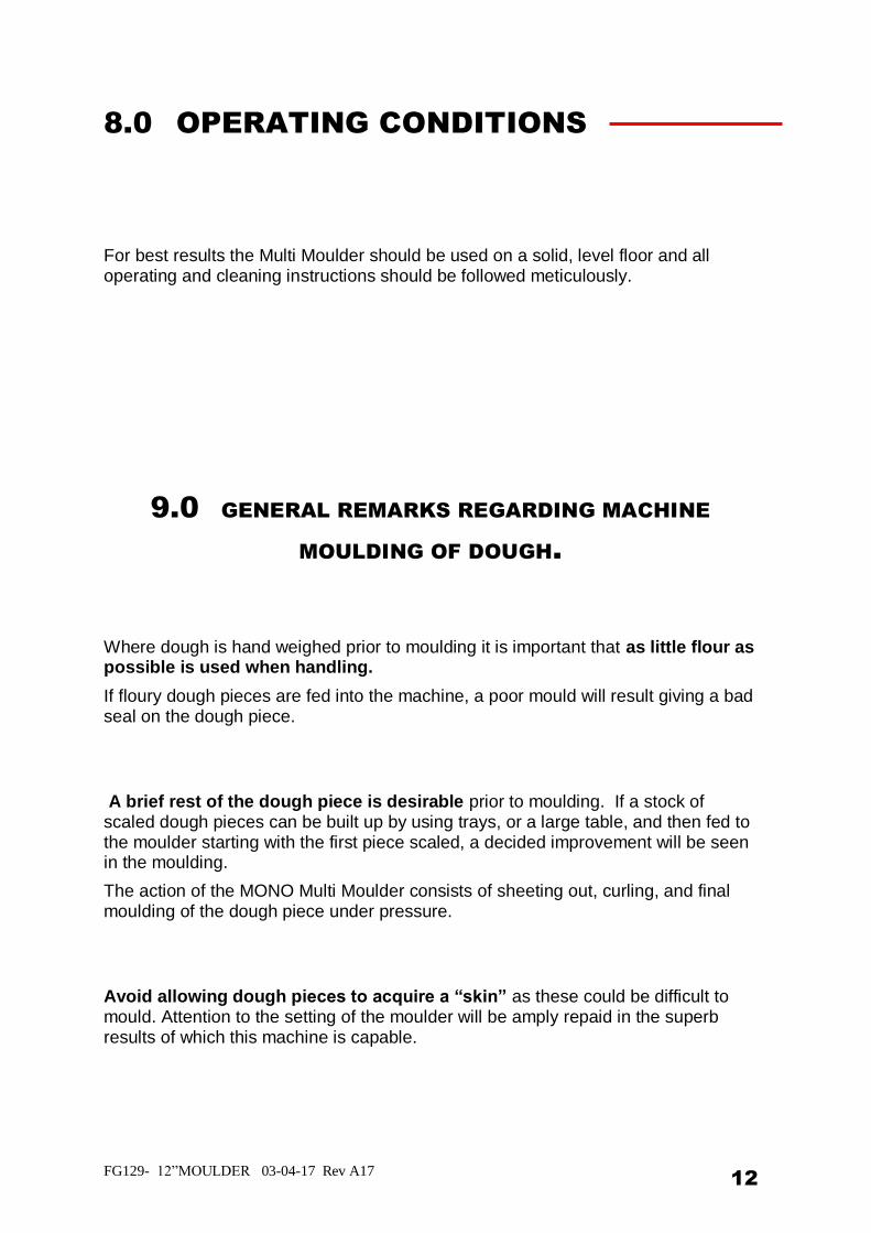
6 Unscrew rear panel nuts (9) using a spanner and remove rear panel (10). Clean belting on panel and remove any debris from around belt edges on machine. 7 Replace rear panel ensuring belting is correctly positioned before tightening
nuts (9).
8 Remove pressure board (11) by first winding handle (12) to move it to its
lowest position, lifting it out of its slots and sliding the board out from the front of the machine.
Wash board in solution of sterilising solution and hot water. Dry thoroughly. 9 Scrape dough belt with a plastic scraper.
DO NOT USE A METAL SCRAPER. The belt will have to be inched forward
to gain access to all parts of its surface.
10 Brush down external surfaces of machine and clean with solution of sterilising solution and hot water. Pay particular attention to handles, levers and controls.
9
10
11
12
9
FG129- 12”MOULDER 03-04-17 Rev A17 12
8.0 OPERATING CONDITIONS
For best results the Multi Moulder should be used on a solid, level floor and all operating and cleaning instructions should be followed meticulously.
9.0 GENERAL REMARKS REGARDING MACHINE
MOULDING OF DOUGH.
Where dough is hand weighed prior to moulding it is important that as little flour as possible is used when handling.
If floury dough pieces are fed into the machine, a poor mould will result giving a bad seal on the dough piece.
A brief rest of the dough piece is desirable prior to moulding. If a stock of scaled dough pieces can be built up by using trays, or a large table, and then fed to the moulder starting with the first piece scaled, a decided improvement will be seen in the moulding.
The action of the MONO Multi Moulder consists of sheeting out, curling, and final moulding of the dough piece under pressure.
Avoid allowing dough pieces to acquire a “skin” as these could be difficult to mould. Attention to the setting of the moulder will be amply repaid in the superb results of which this machine is capable.
FG129- 12”MOULDER 03-04-17 Rev A17 13
10.0 OPERATING INSTRUCTIONS
A. Primary Adjustments B. Sheeting Gap C. Moulding pressure D. Starting
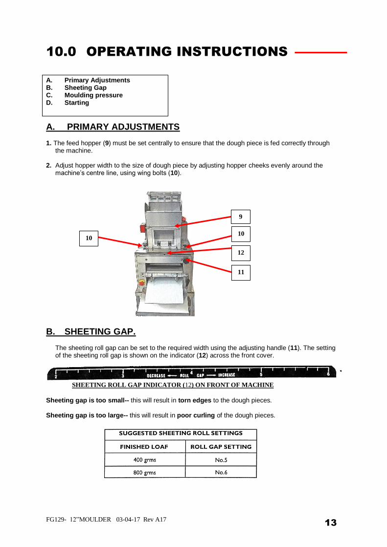
A. PRIMARY ADJUSTMENTS 1. The feed hopper (9) must be set centrally to ensure that the dough piece is fed correctly through
the machine. 2. Adjust hopper width to the size of dough piece by adjusting hopper cheeks evenly around the
machine’s centre line, using wing bolts (10).
B. SHEETING GAP.
The sheeting roll gap can be set to the required width using the adjusting handle (11). The setting of the sheeting roll gap is shown on the indicator (12) across the front cover.
Sheeting gap is too small-- this will result in torn edges to the dough pieces. Sheeting gap is too large-- this will result in poor curling of the dough pieces.
SHEETING ROLL GAP INDICATOR (12) ON FRONT OF MACHINE
9
10 10
12
11
FG129- 12”MOULDER 03-04-17 Rev A17 14
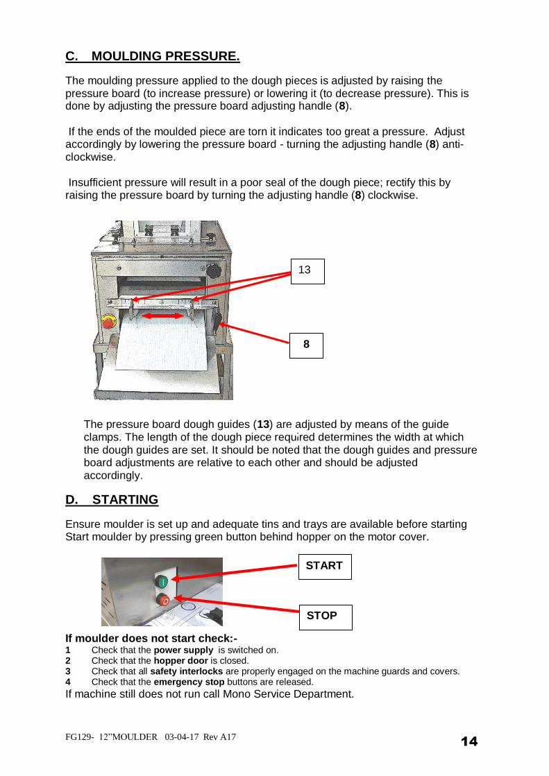
C. MOULDING PRESSURE.
The moulding pressure applied to the dough pieces is adjusted by raising the pressure board (to increase pressure) or lowering it (to decrease pressure). This is done by adjusting the pressure board adjusting handle (8).
If the ends of the moulded piece are torn it indicates too great a pressure. Adjust accordingly by lowering the pressure board - turning the adjusting handle (8) anti-clockwise. Insufficient pressure will result in a poor seal of the dough piece; rectify this by raising the pressure board by turning the adjusting handle (8) clockwise.
The pressure board dough guides (13) are adjusted by means of the guide clamps. The length of the dough piece required determines the width at which the dough guides are set. It should be noted that the dough guides and pressure board adjustments are relative to each other and should be adjusted accordingly.
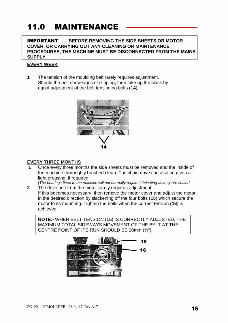
D. STARTING
Ensure moulder is set up and adequate tins and trays are available before starting Start moulder by pressing green button behind hopper on the motor cover. If moulder does not start check:- 1 Check that the power supply is switched on. 2 Check that the hopper door is closed. 3 Check that all safety interlocks are properly engaged on the machine guards and covers. 4 Check that the emergency stop buttons are released.
If machine still does not run call Mono Service Department.
STOP
START
13
8
FG129- 12”MOULDER 03-04-17 Rev A17 15
11.0 MAINTENANCE
IMPORTANT BEFORE REMOVING THE SIDE SHEETS OR MOTOR
COVER, OR CARRYING OUT ANY CLEANING OR MAINTENANCE PROCEDURES, THE MACHINE MUST BE DISCONNECTED FROM THE MAINS SUPPLY.
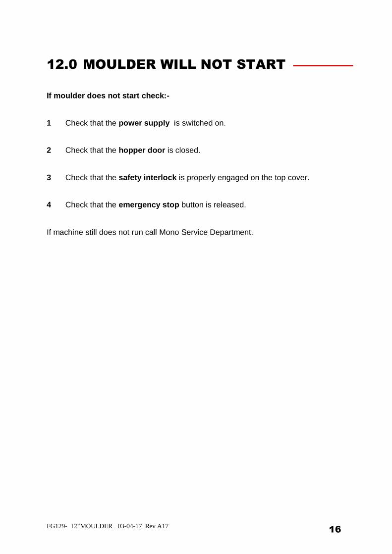
EVERY WEEK
1 The tension of the moulding belt rarely requires adjustment. Should the belt show signs of slipping, then take up the slack by equal adjustment of the belt tensioning bolts (14). EVERY THREE MONTHS 1 Once every three months the side sheets must be removed and the inside of
the machine thoroughly brushed clean. The chain drive can also be given a light greasing, if required. (The bearings fitted to the machine will not normally require lubricating as they are sealed.
2 The drive belt from the motor rarely requires adjustment. If this becomes necessary, then remove the motor cover and adjust the motor in the desired direction by slackening off the four bolts (15) which secure the motor to its mounting. Tighten the bolts when the correct tension (16) is
achieved.
NOTE:- WHEN BELT TENSION (15) IS CORRECTLY ADJUSTED, THE MAXIMUM TOTAL SIDEWAYS MOVEMENT OF THE BELT AT THE CENTRE POINT OF ITS RUN SHOULD BE 20mm (¾").
14
16
15
FG129- 12”MOULDER 03-04-17 Rev A17 16
12.0 MOULDER WILL NOT START
If moulder does not start check:-
1 Check that the power supply is switched on. 2 Check that the hopper door is closed.
3 Check that the safety interlock is properly engaged on the top cover. 4 Check that the emergency stop button is released.
If machine still does not run call Mono Service Department.

FG129- 12”MOULDER 03-04-17 Rev A17 17
13.0 SERVICE
If a fault arises, please do not hesitate to contact the
Customer Service Department, quoting the machine serial number
on the silver information plate of the machine and on the front cover of this
manual
.
MONO Queensway
Swansea West Industrial Estate Swansea. SA5 4EB
UK
email:[email protected] Spares Tel. +44(0)1792 564039
Web site: www.monoequip.com
Main Tel. 01792 561234
Fax. 01792 561016
FG129- 12”MOULDER 03-04-17 Rev A17 18
14.0 SPARES
GENERAL SPARES PART NUMBER TO ORDER RETURN FLAP 129K03P03700 MOULDING BELT A900-22-041 PRESSURE BOARD FELT A900-22-025 SWING PLATE HANDLE P700-07-011 SWING PLATE INDICATOR ASSEMBLY 007-04-02600 (MATCHED PAIR OF SCREWS AND NUTS) 12 TOOTH SPROCKET 129K08D01600 18 TOOTH SPROCKET 129K08D01500 CONVEYOR AND TRANSMISSION BEARING A900-06-023 SHEETING ROLLER BEARINGS A900-06-023 DRIVE CHAIN (SHEETING ROLL) 129K08P02000 DRIVE CHAIN A900-08-007 JOIN LINK A900-08-011 DRIVE CHAIN TENSIONER 007K08-D01100 DRIVE BELT A900-21-025 SHEETING ROLL SCRAPERS:- FRONT 129K05D04200 REAR 129K05D04000 MOULDING FELT CLAMP 129K05D02500 MOULDING FELT HOOK 129K05D02600 OFFTAKE TRAY 169-02D04000 OFFTAKE TRAY SUPPORT PILLAR P700-09-012
Continued on next page
FG129- 12”MOULDER 03-04-17 Rev A17 19
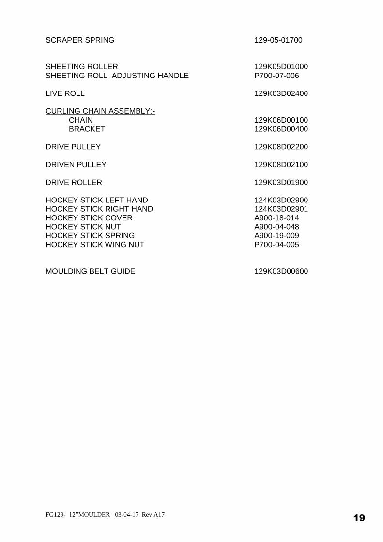
SCRAPER SPRING 129-05-01700 SHEETING ROLLER 129K05D01000 SHEETING ROLL ADJUSTING HANDLE P700-07-006 LIVE ROLL 129K03D02400 CURLING CHAIN ASSEMBLY:- CHAIN 129K06D00100 BRACKET 129K06D00400 DRIVE PULLEY 129K08D02200 DRIVEN PULLEY 129K08D02100 DRIVE ROLLER 129K03D01900 HOCKEY STICK LEFT HAND 124K03D02900 HOCKEY STICK RIGHT HAND 124K03D02901 HOCKEY STICK COVER A900-18-014 HOCKEY STICK NUT A900-04-048 HOCKEY STICK SPRING A900-19-009 HOCKEY STICK WING NUT P700-04-005 MOULDING BELT GUIDE 129K03D00600
15.0 ELECTRICS
FG129- 12”MOULDER 03-04-17 Rev A17 21
FG129- 12”MOULDER 03-04-17 Rev A17 22
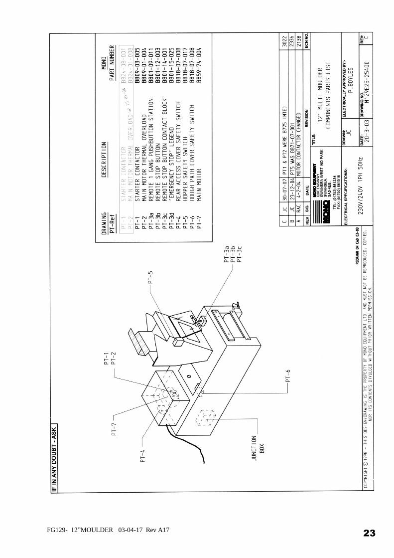
FG129- 12”MOULDER 03-04-17 Rev A17 23
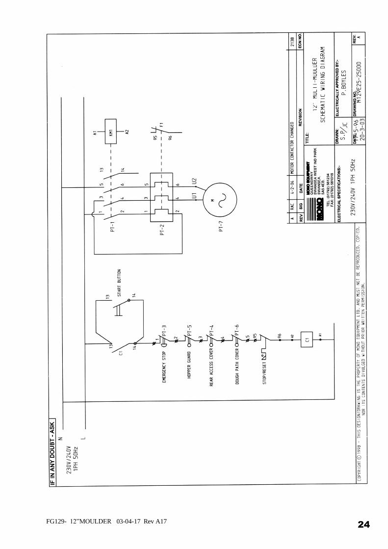
FG129- 12”MOULDER 03-04-17 Rev A17 24
FG129- 12”MOULDER 03-04-17 Rev A17 25
MONO Equipment
Queensway, Swansea West Industrial Park,
Swansea, SA5 4EB
UK
Tel. +44(0)1792 561234 Fax. 01792 561016
Spares Tel. +44(0)1792 564039
Email:[email protected]
www.monoequip.com
As it is our policy to improve our machines continuously, we reserve the right to change specifications without prior notice.
DISPOSAL CARE SHOULD BE TAKEN WHEN THE MACHINE COMES TO THE END OF ITS WORKING LIFE. ALL PARTS SHOULD BE DISPOSED OF IN THE APPROPRIATE PLACE, EITHER BY RECYCLING OR OTHER MEANS OF DISPOSAL THAT COMPLIES WITH LOCAL REGULATIONS.
(IN UK, ENVIRONMENTAL PROTECTION ACT 1990 APPLIES)