modular compact remote power panel - pdicorp.com filemodular compact remote power panel 2 thank you...
TRANSCRIPT

Modular Compact
Remote Power Panel
Installation and Operation
Ctrl Nr: PM375115
Revision: 002

Modular Compact Remote Power Panel
2
Thank you for your recent purchase of a Modular Compact Remote Power Panel from Power
Distribution, Inc.
For safety reasons as well as to ensure optimal performance of your Modular Compact Remote
Power Panel, please carefully read the instructions before trying to install, operate, service, or
maintain the system.
For any questions regarding the installation, operation, service or maintenance of your Modular
Compact Remote Power Panel, please contact us:
Power Distribution, Inc. | 4200 Oakleys Court | Richmond, VA 23223
+1 804 737 9880 | +1 800 225 4838
pdicorp.com | [email protected]
Modular Compact Remote Power Panel
Installation and Operation
Ctrl Nr: PM375115 Rev 002
© 2017 by Power Distribution, Inc. All rights reserved.
Release Date: February 2017
Cover Photo: Modular Compact Remote Power Panel
PDI, WaveStar, JCOMM, Powercube, QUAD-WYE, QUIKSWITCH, and DynaCool On-demand
Cooling System are registered trademarks of Power Distribution, Inc. Other trademarks are held by
their respective owners.
Power Distribution, Inc. (PDI)
Power Distribution, Inc. (PDI) designs, manufactures, and services mission critical power distribution,
static switching, and power monitoring equipment for corporate data centers, alternative energy,
industrial and commercial customers around the world. For over 35 years, PDI has served the data
center and alternative energy markets providing flexible solutions with the widest range of products in
the industry.

Contents
3
Contents
Safety ............................................................................................... 5
1 Installation Planning ................................................................ 6
1.1 Modular Compact RPP Summary .............................................................. 6
1.2 Modular Compact RPP Internal Feature Configurations ................................ 6
1.3 Modular Compact RPP Specification .......................................................... 7
1.4 Installing Modular Compact RPP Cabinets .................................................. 7
1.1 External Cabinet Configurations ............................................................... 7
1.1.1 Single Unit .................................................................................. 7
1.1.2 Cluster Configurations .................................................................. 9
1.2 Modular Compact RPP Electrical Configurations ........................................ 11
2 Installation ............................................................................ 12
2.1 Receiving and Unpacking Unit(s) ............................................................ 12
2.2 Move the Unit to the Installation Location ................................................ 13
2.3 Installing Modular Compact RPP Cabinets ................................................ 13
2.4 Power Wiring ....................................................................................... 15
2.4.1 Cable Entry/Exit ........................................................................ 15
2.4.2 Input Power Connections ............................................................ 16
2.4.3 Output Power Connections .......................................................... 18
3 Initial Startup ........................................................................ 19
3.1 Pre-Startup Inspection .......................................................................... 19
3.2 Startup ............................................................................................... 19
4 Operating Procedures ............................................................ 21
4.1 Initial System Startup ........................................................................... 21
4.2 Normal System Startup ......................................................................... 21
4.3 Normal Shutdown ................................................................................ 21
4.4 Mission Critical Modular Compact RPP Dual Input Transfer Procedures ........ 21
4.4.1 Normal Operation ...................................................................... 22
4.4.2 Transfer from Primary Source to Alternate Source.......................... 22
4.4.3 Transfer from Alternate Source to Primary Source.......................... 22
5 Monitoring .............................................................................. 23
5.1 BCMS ................................................................................................. 23
5.2 Color Monitor and Protocols ................................................................... 23
5.3 Customer Network Connections ............................................................. 24

Modular Compact Remote Power Panel
4
5.3.1 Modbus Connections .................................................................. 24
5.3.2 Ethernet Upstream Cables........................................................... 24
5.4 Networking Modular Compact RPPs Together ........................................... 24
5.5 Modbus Addressing .............................................................................. 26
5.6 Network Connections Details ................................................................. 26
5.6.1 Color Monitor Network Connections .............................................. 26
5.6.2 Modbus RTU Ports ...................................................................... 27
5.6.3 Modbus RTU 2-Wire vs. 4-Wire Configuration ................................ 28
5.6.4 Modbus RTU Upstream Cable Specification .................................... 28
5.6.5 Modbus RTU Cable Biasing and Termination .................................. 28
Figures
Figure 1 Modular Compact RPP Sections with Features Summary ............................................................. 6 Figure 2 Single Modular Compact RPP Outline Drawing ............................................................................. 8 Figure 3 Modular Compact RPP Side-by-Side Configurations ..................................................................... 9 Figure 4 Back-to-Back and Back-to-Back with Sides Clusters ................................................................... 10 Figure 5 Modular Compact RPP Electrical Configurations with Square D NQ Panelboards ..................... 11 Figure 6 Shipping: Bolt and Wood Screw Locations ................................................................................... 14 Figure 7 Top and Bottom Cable Entry/Exit ................................................................................................. 15 Figure 8 Modular Compact RPP Component Layouts with 42-Pole and 84-Pole Panelboards ................. 17 Figure 9 Mission Critical Transfer Controls ................................................................................................. 22 Figure 10 Modbus Terminal Block in Display/Control Compartment .......................................................... 24 Figure 11 Modbus Wiring in a Modular Cluster........................................................................................... 25 Figure 12 BCMS PCB Modbus Connection in Display/Control Section ..................................................... 25 Figure 13 Modbus Addressing .................................................................................................................... 26 Figure 14 Color Monitor Backpanel Network Connections ......................................................................... 27
Tables
Table 1 Modular Compact RPP Location Planning Information ................................................................... 7 Table 2 Pin-Out for Modbus Headers ......................................................................................................... 27

Safety
5
Safety
Please pay special attention to the use of “Danger” symbols throughout this manual indicating electrical or
other safety hazards. Following these safety instructions is extremely important to avoid possible injury or
death.
DANGER!
This symbol is used throughout this manual to indicate the presence of high
voltages, representing a hazard for electric shock, burn or explosion. Follow the
instructions carefully to avoid serious or fatal injury.
Follow safe electrical work practices:
Electrical equipment should be installed, operated, serviced, and maintained only by qualified
personnel and in accordance with all local safety codes. Power Distribution, Inc. assumes no
responsibility for any consequences arising out of the use of this manual. This document should
not be viewed as sufficient by otherwise non-qualified personnel to operate, service, or maintain
the equipment discussed.
Disconnect and lock-out all power supplying equipment before working on or installing Modular
Compact Remote Power Panel components. Use a properly rated voltage sensing device to
confirm power is OFF.
Electrical equipment should be installed, operated, serviced, and maintained only by qualified
personnel and in accordance with all local safety codes. Power Distribution, Inc. assumes no
responsibility for any consequences arising out of the use of this manual. This document should
not be viewed as sufficient by otherwise non-qualified personnel to operate, service, or maintain
the equipment discussed.
Read, understand, and follow the instructions before installing this product.
Install device in an appropriate electrical enclosure per local regulations.
ESD sensitive equipment. Ground yourself, discharge any static charge and ensure that the
device is effectively grounded before handling the unit.
An installed Modular Compact Remote Power Panel must be securely fastened to a leveled floor or a
plumbed wall.
Modular Compact Remote Power Panel
6
1 Installation Planning
1.1 Modular Compact RPP Summary
The Modular Compact Remote Power Panel (RPP) is a versatile RPP with a small footprint:
Two units can fit on a standard 24" x 24" floor tile.
Any unit can be floor mounted or wall mounted.
All units are front-access only for normal maintenance.
Cabinets can be installed together in various combinations, as single units or in side-by-side,
back-to-back, or back-to-back-plus-side(s) modular clusters. Internal unit features do not restrict
cabinet combinations.
Internal feature sets can be selected and combined for nearly any RPP application.
A single WaveStar® Color Monitor can display Branch Circuit Monitoring System (BCMS) power
monitoring information for up to seven (7) units with up to fourteen (14) panelboards. An
alternative Square D monitoring system is also available.
Certifications are pending through ETL for these standards: UL 60950, UL 891, and CS 22.2.
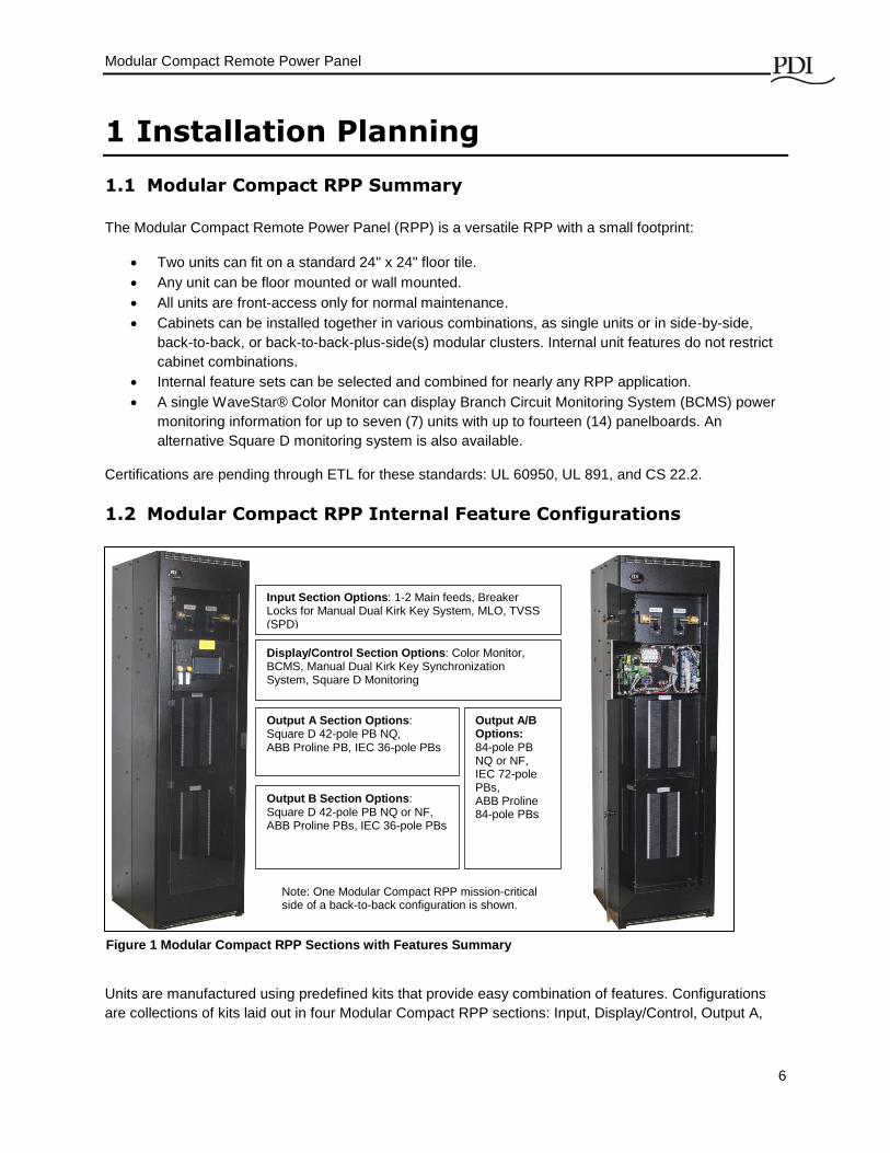
1.2 Modular Compact RPP Internal Feature Configurations
Units are manufactured using predefined kits that provide easy combination of features. Configurations
are collections of kits laid out in four Modular Compact RPP sections: Input, Display/Control, Output A,
Input Section Options: 1-2 Main feeds, Breaker Locks for Manual Dual Kirk Key System, MLO, TVSS (SPD)
Display/Control Section Options: Color Monitor, BCMS, Manual Dual Kirk Key Synchronization System, Square D Monitoring
Output A Section Options: Square D 42-pole PB NQ, ABB Proline PB, IEC 36-pole PBs
Output B Section Options: Square D 42-pole PB NQ or NF, ABB Proline PBs, IEC 36-pole PBs
Output A/B Options: 84-pole PB NQ or NF, IEC 72-pole PBs, ABB Proline 84-pole PBs
Note: One Modular Compact RPP mission-critical side of a back-to-back configuration is shown.
Figure 1 Modular Compact RPP Sections with Features Summary
Modular Compact RPP Installation Planning
7
and Output B. Internal features and electrical configurations are independent of the way the unit is
mounted or clustered with other units.
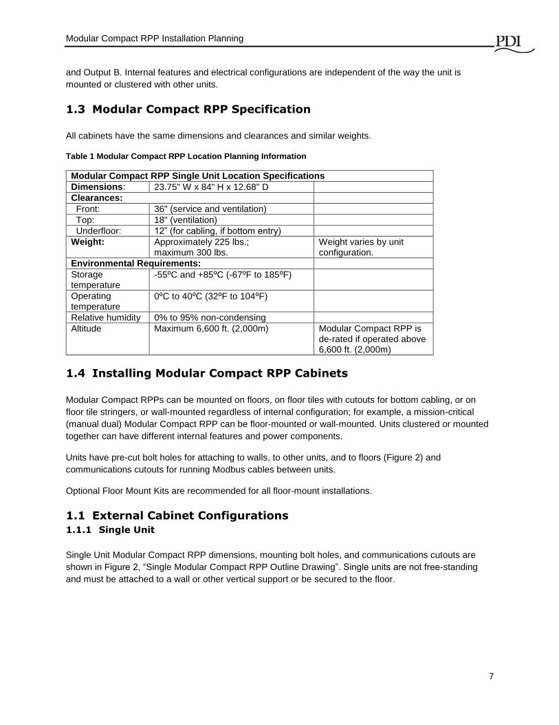
1.3 Modular Compact RPP Specification
All cabinets have the same dimensions and clearances and similar weights.
Table 1 Modular Compact RPP Location Planning Information
Modular Compact RPP Single Unit Location Specifications
Dimensions: 23.75" W x 84" H x 12.68" D
Clearances:
Front: 36" (service and ventilation)
Top: 18" (ventilation)
Underfloor: 12” (for cabling, if bottom entry)
Weight: Approximately 225 lbs.; maximum 300 lbs.
Weight varies by unit configuration.
Environmental Requirements:
Storage temperature
-55⁰C and +85⁰C (-67⁰F to 185⁰F)
Operating temperature
0⁰C to 40⁰C (32⁰F to 104⁰F)
Relative humidity 0% to 95% non-condensing
Altitude Maximum 6,600 ft. (2,000m) Modular Compact RPP is de-rated if operated above 6,600 ft. (2,000m)
1.4 Installing Modular Compact RPP Cabinets
Modular Compact RPPs can be mounted on floors, on floor tiles with cutouts for bottom cabling, or on
floor tile stringers, or wall-mounted regardless of internal configuration; for example, a mission-critical
(manual dual) Modular Compact RPP can be floor-mounted or wall-mounted. Units clustered or mounted
together can have different internal features and power components.
Units have pre-cut bolt holes for attaching to walls, to other units, and to floors (Figure 2) and
communications cutouts for running Modbus cables between units.
Optional Floor Mount Kits are recommended for all floor-mount installations.
1.1 External Cabinet Configurations
1.1.1 Single Unit
Single Unit Modular Compact RPP dimensions, mounting bolt holes, and communications cutouts are
shown in Figure 2, “Single Modular Compact RPP Outline Drawing”. Single units are not free-standing
and must be attached to a wall or other vertical support or be secured to the floor.

Modular Compact Remote Power Panel
8
Back-to-Back Configuration Overhead View
Top solid plate and bottom pre-punched conduit plate are interchangeable.
Bolt holes for attaching units to vertical supports or to each other are 0.44 inches.
Communications cutouts for running Modbus cables between units are 1.09 inches.
Figure 2 Single Modular Compact RPP Outline Drawing
Modular Compact RPP Installation Planning
9
1.1.2 Cluster Configurations
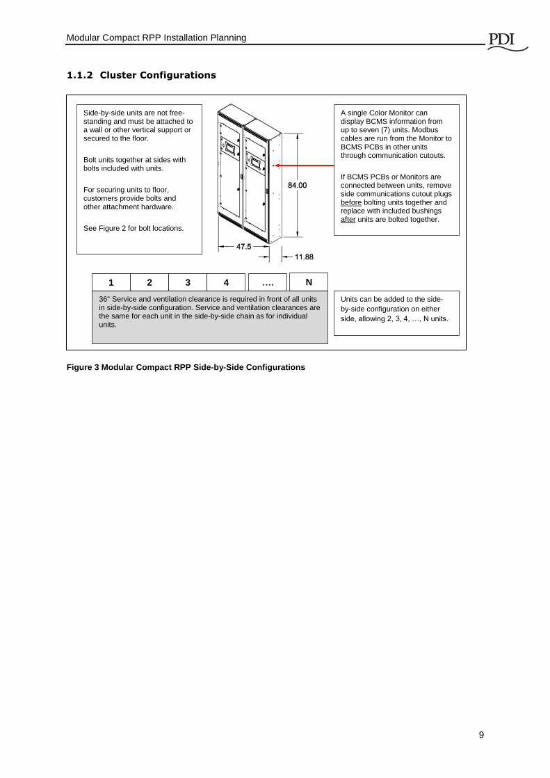
Figure 3 Modular Compact RPP Side-by-Side Configurations
Side-by-side units are not free-standing and must be attached to a wall or other vertical support or secured to the floor.
Bolt units together at sides with bolts included with units.
For securing units to floor, customers provide bolts and other attachment hardware.
See Figure 2 for bolt locations.
A single Color Monitor can display BCMS information from up to seven (7) units. Modbus cables are run from the Monitor to BCMS PCBs in other units through communication cutouts.
If BCMS PCBs or Monitors are connected between units, remove side communications cutout plugs before bolting units together and replace with included bushings after units are bolted together.
1 2 3 4
36" Service and ventilation clearance is required in front of all units in side-by-side configuration. Service and ventilation clearances are the same for each unit in the side-by-side chain as for individual units.
N ….
Units can be added to the side-
by-side configuration on either
side, allowing 2, 3, 4, …, N units.
Modular Compact Remote Power Panel
10
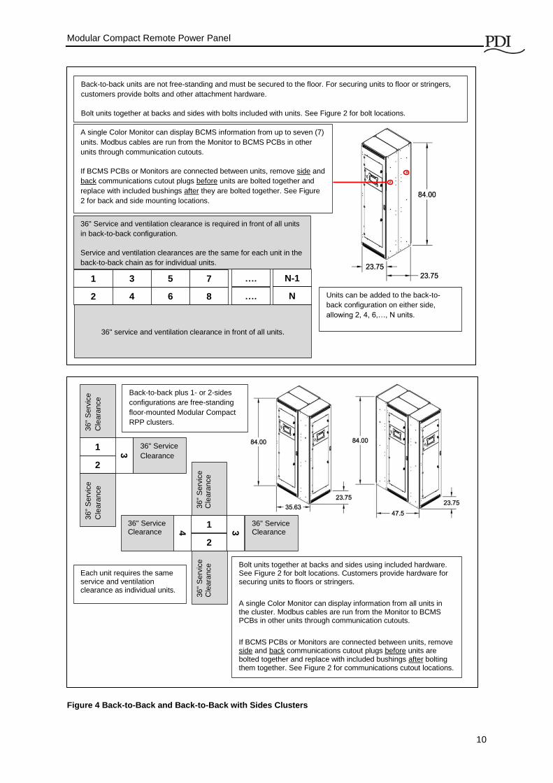
Figure 4 Back-to-Back and Back-to-Back with Sides Clusters
Units can be added to the back-to-
back configuration on either side,
allowing 2, 4, 6,…, N units.
1
2
3
4
5
6
7
8
N-1
N
….
….
36" Service and ventilation clearance is required in front of all units
in back-to-back configuration.
Service and ventilation clearances are the same for each unit in the
back-to-back chain as for individual units.
36" service and ventilation clearance in front of all units.
Back-to-back units are not free-standing and must be secured to the floor. For securing units to floor or stringers,
customers provide bolts and other attachment hardware.
Bolt units together at backs and sides with bolts included with units. See Figure 2 for bolt locations.
A single Color Monitor can display BCMS information from up to seven (7)
units. Modbus cables are run from the Monitor to BCMS PCBs in other
units through communication cutouts.
If BCMS PCBs or Monitors are connected between units, remove side and
back communications cutout plugs before units are bolted together and
replace with included bushings after they are bolted together. See Figure
2 for back and side mounting locations.
36" Service
Clearance 1
2
3
36"
Serv
ice
Cle
ara
nce
36"
Serv
ice
Cle
ara
nce
Each unit requires the same service and ventilation clearance as individual units.
Bolt units together at backs and sides using included hardware. See Figure 2 for bolt locations. Customers provide hardware for securing units to floors or stringers.
A single Color Monitor can display information from all units in the cluster. Modbus cables are run from the Monitor to BCMS PCBs in other units through communication cutouts.
If BCMS PCBs or Monitors are connected between units, remove side and back communications cutout plugs before units are bolted together and replace with included bushings after bolting them together. See Figure 2 for communications cutout locations.
36" Service Clearance
1
2
3
4
36" Service Clearance
36"
Serv
ice
Cle
ara
nce
36"
Serv
ice
Cle
ara
nce
Back-to-back plus 1- or 2-sides
configurations are free-standing
floor-mounted Modular Compact
RPP clusters.

Modular Compact RPP Installation Planning
11
1.2 Modular Compact RPP Electrical Configurations
Modular Compact RPPs can have a variety of power configurations. The configurations below are
created using Square D NQ-frame panelboards. Other configurations are available using Square D
NF, IEC (SEA), and ABB Proline panelboards. Amperages and voltages vary by configurations.
Consult your PDI sales representative for configuration options. PDI Application Engineering can
assist you in creating Modular Compact RPP configurations suitable to your applications.
Figure 5 Modular Compact RPP Electrical Configurations with Square D NQ Panelboards
Dual Input Sources
400A Max Input per
Feed/
(2) NQ Panelboards
(42) poles each
225A Max Input per
Feed/
(2) NQ Panelboards
(42) poles each
400A Max. Input
(1) 400A Circuit
Breaker
(1) NQ Panelboard
(84) Poles
450A Max. Input/
(2) 225A or 400A
Circuit Breakers/
(2) NQ Panelboards
(42) Poles each
Single Input Source
Note 2: All Modular Compact RPPs with NQ panelboards allow maximum 240VAC.
Note 3: When installed on dual input systems, the Color Monitor has a relay to obtain power from the other power source when one source loses power.
Note 1: External
junction box may be
required with 400A
panelboard circuit
breakers in this
configuration.
Mission Critical Modular Compact RPPs are created by adding the Kirk-Key feature to dual input source Modular Compact RPPs.
Mission Critical Modular Compact RPPs

Modular Compact Remote Power Panel
12
2 Installation
2.1 Receiving and Unpacking Unit(s)
Modular Compact RPPs are shipped standing upright bolted together in pairs in a back-to-back
configuration and attached to pallets with wood screws. When an order has an odd number of units,
one unit is shipped standing upright alone. Units can also be shipped singly at customer request.
Upon receiving a Modular Compact RPP pallet and before removing packaging, inspect packaging for
visible damage that could affect the Modular Compact RPP(s). If damage is evident notify PDI and the
shipping company (see below).
Carefully cut retaining bands and remove packaging from units, but leave units attached to their
pallets. Use care to not puncture or scratch the Modular Compact RPP cabinets with cutting tools.
Retaining bands are under tension; cut them carefully. Wear eye protection
and protective clothing when cutting bands.
After removing packaging, check units again for damage, such as scratches, dents, or cracks.
NOTE: If any damage is evident during unpacking, notify the shipping company and PDI. Claims
should be filed with the shipping company at time of delivery. Damage must be noted on the bill of
lading. Failure to properly document damage may void the warranty.
Notify PDI Service Department at
Power Distribution Inc.
4200 Oakleys Court
Richmond, Virginia 23223
(800)-225-4838
DANGER!
A licensed electrician must install each unit. Startup by a PDI certified technician is also required to validate the warranty.
Severe or fatal injury can result from electrical shock during contact with high voltage conductors, monitoring PCBs, or similar equipment.
Disconnect power before drilling holes, attaching cables or conduit, or connecting PDUs to other power distribution equipment.
Use Lock Out/Tag Out procedures.
Wear suitable personal protective clothing and use protective equipment for performing mechanical and electrical installations.
Leave ample space for attaching and routing wires.

Installation
13
2.2 Move the Unit to the Installation Location
Before moving a unit, plan the path from the receiving area to its installation location. Review
obstacles, floor weight capacity, corners, etc.
Using a fork lift or pallet jack, move the unit(s) (still secured to their shipping pallet) as close to the
installation location as possible over your pre-planned route.
2.3 Installing Modular Compact RPP Cabinets
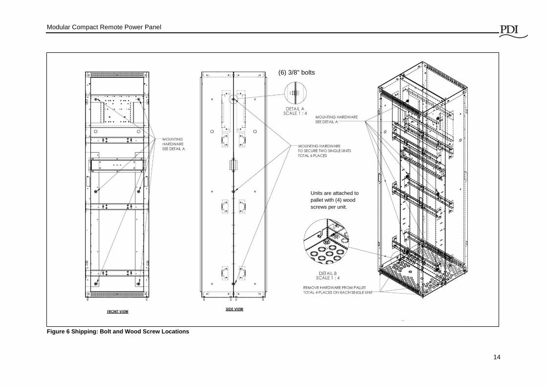
Most units are shipped bolted together back-to-back with (6) 3/8" bolts. See Figure 6 for bolt locations.
If units are to be installed in a back-to-back configuration, leave them bolted together as shipped.
Otherwise, remove bolts and nuts and save.
Remove the wood screws attaching the unit(s) to the pallet (Figure 6). Make sure units do not tip over.
Slide or lift each unit or bolted-together pair carefully off the pallet onto the correct predetermined
location. Individual units can usually be lifted by three or four persons. (Check the weight of your
unit(s) given in your submittal package.) Take care not to scratch or damage the unit(s). Units do not
have casters and cannot be rolled.
If mounting on a floor tile, the floor tile cutout should be made in advance.
If mounting on floor tile stringers, units should be left bolted together in a back-to-back
configuration and secured to the stringers. Single units are not stable and must be secured to
the floor or wall.
If mounting to a wall or vertical support, place the unit in the correct position and bolt to the
support.
Once each RPP is in its final position, inspect for loose connections or displacement caused by
shipping. Ensure all lug connections in ground bus, neutral bus, terminal blocks, etc. are tight and
secured.
Check the main input feeder connections at the main breaker to be sure vibration has not loosened
the terminal screws. Check the feeders from the load side of the main breaker to the primary side of
the panels.
Important: Customers are responsible for securing units to vertical supports or to the floor.
Refer to installation planning information in Chapter 1 for physical configurations and mounting
information.
Bolts for bolting units together in a modular cluster are shipped with units. Customers must supply
their own hardware for attaching units to the floor, stringers, or a wall.
Bolt holes and communications cutouts are shipped with plugs installed.
Remove bolt-hole plugs and replace with provided bolts for when bolting units together. 3/8-in
bolts for attaching cabinets to each other are included in the BOM for the unit.
Communications cutouts allow you to run Modbus cables between units. Replace plugs in
communication cutouts with bushings, included in each unit’s BOM. For communications
cutouts you intend to use, remove plugs before you bolt units together and replace with
bushings after bolting them together.
Modular Compact Remote Power Panel
14
Figure 6 Shipping: Bolt and Wood Screw Locations
Units are attached to
pallet with (4) wood
screws per unit.
(6) 3/8" bolts

Modular Compact Remote Power Panel
15
2.4 Power Wiring
Power wiring must comply with NEC and applicable local codes and should be wired by licensed
electricians. Reference your submittal package for 1-line drawings specific to your Modular Compact
RPP configuration.
2.4.1 Cable Entry/Exit
Cable entry/exit can be from top and/or bottom. Top and bottom plates can be interchanged according
to customer cabling requirements.
The bottom plate has pre-punched knockouts for 1/2" and 3/4" conduit.
o 60 knockouts for 1/2" conduit (0.88" dia.)
o 24 double knockouts for 3/4" conduit (1.09 dia.) and 1/2" (0.88" dia.) conduit.
o 2 x main-feed conduit knockouts; (2) conduit knockouts can be enlarged up to 4".
The top plate can be used for cutouts.
Open or remove door and execute knockouts for an appropriate number of conduits for intended
cable connections.
Figure 7 Top and Bottom Cable Entry/Exit
(Bottom) Plate with pre-punched knockouts
(2) Knockouts for conduits for main feed wires can be enlarged to maximum 4".
Top Plate

Modular Compact Remote Power Panel
16
2.4.2 Input Power Connections
Figure 8 shows component locations for both 84-pole and 42-pole panelboards and neutral and
ground busbar connections.
Refer to NEC (2014) 310.16 and your local codes for wiring standards for phase and neutral wiring.
Customer-supplied cable connections should be 75⁰C copper wire.
Refer to NEC (2014) 250.122 and your local codes for ground wiring standards.
Maximum cable sizes: 250 kcmil (MCM) Copper.
Minimum recommended wire sizes:
o Main feed input:
225A main feed input: 4/0 wire (rated for 230A @75⁰ C) for each phase
400A or 450A main feed input: (2) x 4/0 (rated for 450A @75⁰ C), (2) cables
per phase.
o Neutral Busbar, neutrals are sized at 200% phase cables and need double-sized
wires :
225A (2) x 250 kcmil (MCM) or (2) x 4/0 wire (rated for 230A @75⁰ C)
400A: (4) x 250 kcmil (MCM) or (4) x 4/0 wire (rated for 450A @75⁰ C)
o Ground Busbar:
225A: #4 AWG Copper or #2 AWG Aluminum
400A: #3 AWG Copper or #1 AWG Aluminum
o Isolated Ground (optional): Use same wire size as ground.
Maximum main feed conduit size: (2) conduits, 4-in. maximum, sized for (6)-wires
3P + 2N + 1G (Oversized neutral requires (2) cables.)
Pull input power conduit through knockouts.
Pull cables through units to main breaker lugs. Connect input cables to main circuit breaker lugs and
torque lugs to circuit breaker manufacturer’s specification.
Important!
Grounding for this equipment must comply with NEC and local building and electrical codes.

Modular Compact Remote Power Panel
17
Figure 8 Modular Compact RPP Component Layouts with 42-Pole and 84-Pole Panelboards

Installation
18
2.4.3 Output Power Connections
Modular Compact RPPs are usually shipped without installed panelboard circuit breakers. Customers
are responsible for installing panelboard circuit breakers, running single phase wires through CT
strips, and connecting circuit breakers to ground strips, neutral strips, and optional isolated ground
strips. Locations are shown on Figure 8.
The output panel boards should have all the output loads balanced at the panelboards in order to
place equivalent current wave forms and magnitude on each output. Distributing the 3-pole breakers
by ampacity evenly across matched panelboards provides optimum balancing. Single phase loads
with high third harmonics should also be evenly balanced across the panelboards. Follow these steps
to properly balance circuits.
1. Divide all output into three (3) categories by breaker pole position (1, 2, 3 pole).
2. Subdivide the three categories by breaker size (ampacity).
3. Assign the largest 3-pole breaker to panelboard #1.
4. If there is an even number of the larger 3-pole breakers, assign them evenly between the
panel boards. If you are unable to assign them evenly, then assign smaller 3 pole
breakers to the panel having fewer breakers.
5. Repeat steps 3 and 4 until all 3-pole breakers are installed.
When determining distribution cable length between panelboard circuit breakers and load equipment,
provide sufficient cable length to avoid stress at the connection point between panelboard breakers
and distribution cables.
When cabling, do not block access to ground and neutral terminals.

Modular Compact Remote Power Panel
19
3 Initial Startup
DANGER!
Do not perform inspection or startup alone. A second qualified person should
be present to provide emergency assistance.
Before applying utility power to the unit, the installing electrician and/or a
factory authorized representative should be present to verify that the
following steps have been performed properly.
3.1 Pre-Startup Inspection
1. Before applying power to the Modular Compact RPP, inspect wiring and connections. Incoming
power to main feeds or MLO lugs should be de-energized and locked out before making this
inspection.
2. Inspect wiring, components, and cabinet for damage.
3. Inspect all power connections for tight connections:
3.1. Ensure that all power lug connections in ground bus, neutral bus, and terminal blocks are
tight and secured.
3.2. Check main feed terminal screws.
3.3. Check the main feed connections from the load side of the main breaker to the primary side
of the panels.
3.4. Torque connections as follows:
3.4.1. For circuit breakers use manufacturer’s recommendations.
3.4.2. For other connections, see the torque table on a label on the inside door of the unit.
4. Inspect unit for debris or foreign objects and remove if present.
5. Check that ventilation openings are clean.
6. Check that service and ventilation clearances satisfy code requirements.
3.2 Startup
Before turning on power to the unit:
1. Confirm that the RPP main feed circuit breaker(s) are in the OFF position. (If a breaker has been
tripped, reset the breaker to the OFF position.)
2. Lock out input power to the unit (PDU, UPS, or building power).
3. Ensure that all of the RPP output circuit breakers are in the OFF position.
4. Visual voltage label check: Verify that the input voltage to the unit matches the input voltage rating
of the unit as identified on the system’s legend label affixed to the interior of the front door.
Check input power:
1. Turn ON input power to one main breaker. (Note: if a main breaker trips to OFF when energized,
it may indicate a fault in the unit. Contact PDI Service at (800)-225-4838.)
2. Measure and record voltages at input to the main feed(s): A-to-B, B-to-C, C-to-A. Incoming
voltage should be + 5% to -10% of the unit’s nominal rating.
3. Check for clockwise phase rotation and voltage at the input main feed circuit breaker(s).
4. Repeat steps 1-3 for second main feed breaker if present.

Modular Compact Remote Power Panel
20
Check monitoring:
1. The Color Monitor should turn on when power is applied to the main feed from which it receives
power. Display panelboard screens for your configuration, but without load, most readings will be
zero. Note: On dual input systems, the Color Monitor has a relay to obtain power from the
second power source, when its primary source loses power or is not enabled.
Sequentially energize loads by turning ON individual panelboards circuit breakers.
Operating Procedures
21
4 Operating Procedures
4.1 Initial System Startup
Perform initial system startup as described in Section 3, Initial Startup,
after an Modular Compact RPP is first installed, or
after an Modular Compact RPP has been subsequently relocated, or
after an Modular Compact RPP has been upgraded or had maintenance performed, or
after an Modular Compact RPP has been de-energized for a significant period of time.
Perform all checklist steps in Section 3.
4.2 Normal System Startup
Verify that all Modular Compact RPP circuit breakers are turned OFF, both main feeds and
panelboard circuit breakers.
Turn ON main feed circuit breaker(s).
If a main feed circuit breaker has been tripped OFF, first reset the breaker by turning it OFF
then ON.
If a main feed circuit breaker trips OFF when energized, a fault may be present in the unit.
Contact PDI Service at (800)-225-4838.
Turn ON power to loads by sequentially turning ON panelboard circuit breakers.
Follow manufacturers’ startup recommendations for load equipment.
4.3 Normal Shutdown
The normal shutdown procedure for an RPP is to first shut down the Modular Compact RPP’s load
equipment according the equipment manufacturers’ instructions. For example, shut down the
operating system on a server, including powering down the server.
Then, turn OFF the associated panelboard circuit breakers on the Modular Compact RPP.
After all panelboard breakers have been turned OFF, turn OFF the main feeds(s) to the Modular
Compact RPP panelboard(s).
If the Modular Compact RPP is to be moved or upgraded, also turn OFF PDU or building power to the
main feeds and lock out power to the Modular Compact RPP.
4.4 Mission Critical Modular Compact RPP Dual Input Transfer
Procedures
A Mission-Critical Modular Compact RPP has dual voltage inputs, but only one at a time supplies
power to the RPP. Voltage can be continuously supplied to the load while one main feed and
panelboard are effectively offline. The dual inputs are switched manually using Kirk Keys with a
Solenoid Key Release (transfer initiate switch). See Figure 9.
Circuit breaker Main 1 is for the Primary Source (1).

Modular Compact Remote Power Panel
22
Circuit breaker Main 2 is for the Alternate Source (2).
Figure 9 Mission Critical Transfer Controls
4.4.1 Normal Operation
The normal status for voltage input is as follows:
1. The Primary Source (1) is supplying power to the critical load.
2. Circuit Breaker Main 1 (Primary Source) is closed and its key is trapped.
3. Circuit Breaker Main 2 (Alternate Source) is locked open with no key trapped.
4. Solenoid Key Interlock is DE-ENERGIZED and the interlock key is trapped.
When the Solenoid Key Release button is lighted, the two sources are synchronized and power can
be transferred from one source to another.
4.4.2 Transfer from Primary Source to Alternate Source
To transfer power input from the Primary Source to the Alternate Source:
1. Depress the Solenoid Key Release (transfer initiate switch). Unlock and remove the key from
the Solenoid Key Interlock.
2. Insert the key into Main 2. Unlock and close Main 2.
3. Open circuit breaker Main 1 and lock open. Remove the key from Main 1.
4. Insert the key into the key interlock and turn to lock.
4.4.3 Transfer from Alternate Source to Primary Source
To transfer power input from the Alternate Source to the Primary Source:
1. Depress the Solenoid Key Release (transfer initiate switch). Unlock and remove the key from
the Solenoid Key Interlock.
2. Insert the key into the Main 1 lock. Unlock and close circuit breaker Main 1.
3. Open circuit breaker Main 2 and lock open. Remove the key from Main 2.
4. Insert the key into the key interlock and turn to lock.
Main 2 Key
Source 2/
Main 2 Circuit Breaker
Main 1 Key
Source 1/
Main 1 Circuit Breaker
Solenoid Key Release
(Transfer Initiate Switch)
Solenoid Key Interlock

Modular Compact Remote Power Panel
23
5 Monitoring
Modular Compact RPPs have several monitoring options:
WaveStar® Monitoring with Color Monitor and Branch Circuit Monitoring System (BCMS).
BCMS only
Square D monitoring
No monitoring
WaveStar monitoring components—the Color Monitor and BCMS —should be ordered with the unit
and installed at the factory.
5.1 BCMS
Each Modular Compact RPP can have one (1) BCMS PCB, which can monitor up to 2 x 42-pole
panelboards or 1 x 84-pole panelboard with their main feeds.
Each panelboard with its associated main feed is represented by a points list. A 42-pole panelboard is
represented by a single panelboard points list. An 84-pole panelboard is represented by two (2)
panelboard points lists.
Points lists are loaded onto BCMS PCBs at the factory. Several points lists are available:
BCMS Normal panelboard points list allows customization of circuit breaker alarms and
warnings for each panelboard circuit.
BCMS KWH points list provides accumulated KWH measurements and other detailed power
information for each panelboard circuit.
BCMS IEC panelboard points list is for IEC format panelboards with 36 or 72 1P circuits.
See the Bibliography for information on downloading points lists from the PDI website.
5.2 Color Monitor and Protocols
When Modular Compact RPPs are combined in a modular cluster, a single Color Monitor can display
power information for up to (7) Modular Compact RPP units or up to (14) panelboards.
The Color Monitor supports several protocols, which can all be used simultaneously.
Downstream Protocol The downstream device network has fixed parameters of Modbus RTU, 9600
baud, EVEN parity.
Upstream Protocols The Monitor has separate upstream ports for Modbus RTU and Ethernet,
supporting these protocols:
Modbus RTU
Ethernet port
o TCP/IP, used by the Color Monitor’s web page server
o Modbus TCP/IP
o SNMP Version 1
For in-depth information on the Color Monitor, including setup, networking, commands and replies,
screens, and web pages, see WaveStar® Color Monitor, Setup and Operation, PM375103.

Modular Compact Remote Power Panel
24
5.3 Customer Network Connections
5.3.1 Modbus Connections
Each Modular Compact RPP with an installed Color Monitor has a terminal block in the
Display/Control section for connecting Modbus RTU wiring. The Color Monitor is connected via
Modbus RTU to the terminal block, allowing customers to make upstream connections without
touching a BCMS PCM or Color Monitor backpanel. A label is attached next to the terminal block
showing Modbus connections.
Figure 10 Modbus Terminal Block in Display/Control Compartment
5.3.2 Ethernet Upstream Cables
The customer network Ethernet cable must be connected directly to the Color Monitor backpanel
(Figure 14). The customer’s choice of Ethernet cable determines the maximum length of Ethernet
cable.
5.4 Networking Modular Compact RPPs Together
A Color Monitor can display power information for up to (7) Modular Compact RPP units or up to (14)
panelboard “devices”. The points lists representing the panelboards on these Modular Compact RPPs
are downstream devices to the Color Monitor. Downstream devices use Modbus RTU protocol.
Each Modular Compact RPP has (1) BCMS PCB that can monitor (2) panelboards. The BCMS PCB
is wired to the Modbus terminal block on its Modular Compact RPP unit (Figure 10).
BCMS PCBs downstream of the Color Monitor should be wired in a Modbus RTU daisy-chain to the
Monitor (Figure 11).
BCMS PCBs have a single Modbus RTU connector for wiring Modbus RTU upstream or downstream
of the PCB (Figure 12).
BCMS PCB
Label mapping the Modbus terminal block will be fixed next to the terminal block.
Each Modular Compact RPP with an installed Color Monitor has a terminal block for Modbus connections in the Display/Control section.

Monitoring
25
Figure 11 Modbus Wiring in a Modular Cluster
Figure 12 BCMS PCB Modbus Connection in Display/Control Section
To Modbus RTU master device (BMS, DCIM, etc.)
TB
Color
Monitor
BCMS PCB BCMS PCB BCMS PCB Ethernet link: Modbus TCP, etc.
In a Modular Cluster, up to (7) units can be monitored through (1) Color Monitor. BCMS PCBs in each unit can be daisy-chained through Modbus RTU links to the Monitor, which is wired to a terminal block (TB).
Modbus RTU
Downstream from Monitor: Modbus RTU Daisy Chain
Upstream from Monitor: Various Protocols Allowed.
BCMS PCB Modbus Terminal Block
Color Monitor Backpanel
Modbus
Connector

Modular Compact Remote Power Panel
26
5.5 Modbus Addressing
Refer to Figure 13, “Modbus Addressing,” with the following bullet points:
The Monitor is a Modbus master to its downstream devices. The upstream Modbus
master cannot directly address these devices, but rather addresses them through the
Monitor. Upstream and downstream are separate Modbus segments.
The Monitor’s upstream address can be set to from 1 to 255, but you must leave enough
addressing capacity for downstream devices. The monitor will not respond to a command
sent to address 0. The address is set during Monitor Setup.
The Monitor’s downstream devices must be assigned consecutive addresses starting at
address 1. Modbus addresses must be assigned in BCMS setup and will be done initially
at the factory. Modbus addresses cannot be assigned by, for example, the BMS.
For upstream addressing these device addresses are remapped as successor addresses
to the Monitor. If the Monitor has upstream address 30, the downstream addresses 1, 2,
3, 4 are remapped to 31, 32, 33, 34 as seen from the BMS or other Modbus Master.
Modbus addressing is the same for Modbus RTU and Modbus TCP/IP.
5.6 Network Connections Details
5.6.1 Color Monitor Network Connections
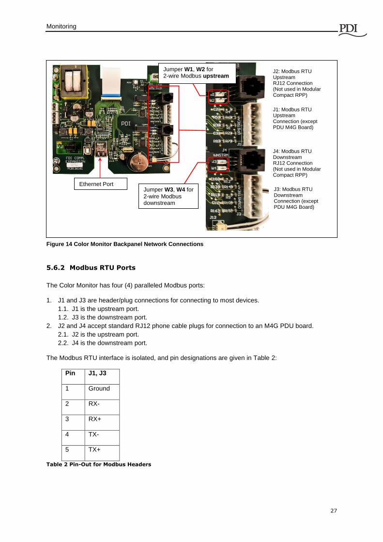
The Color Monitor’s backpanel has Modbus RTU and Ethernet ports (Figure 13).
Modbus RTU backpanel connections are typically made in manufacturing and extended to a terminal
block or external panel for convenient customer access. The customer’s Ethernet cable is connected
directly to the Monitor’s Ethernet port.
1 2 3 4
Downstream Modbus addresses must be assigned sequentially from 1.
BCMS BCMS
PB1 PB2 PB3 PB4
Figure 13 Modbus Addressing
30 = Monitor’s assigned upstream address.
These addresses are visible from the upstream Modbus master: 31 32 33 34
Downstream Modbus addresses are adjusted by the Monitor’s upstream address.
30
To upstream Modbus master (BMS, DCIM, etc.)
Modular Compact RPP1
30
Monitor’s Upstream Modbus Segment Monitor’s Downstream Modbus Segment
Modular Compact RPP2
Monitoring
27
5.6.2 Modbus RTU Ports
The Color Monitor has four (4) paralleled Modbus ports:
1. J1 and J3 are header/plug connections for connecting to most devices.
1.1. J1 is the upstream port.
1.2. J3 is the downstream port.
2. J2 and J4 accept standard RJ12 phone cable plugs for connection to an M4G PDU board.
2.1. J2 is the upstream port.
2.2. J4 is the downstream port.
The Modbus RTU interface is isolated, and pin designations are given in Table 2:
Pin J1, J3
1 Ground
2 RX-
3 RX+
4 TX-
5 TX+
Table 2 Pin-Out for Modbus Headers
J2: Modbus RTU Upstream RJ12 Connection (Not used in Modular Compact RPP)
J4: Modbus RTU Downstream RJ12 Connection (Not used in Modular Compact RPP)
J1: Modbus RTU Upstream Connection (except PDU M4G Board)
J3: Modbus RTU Downstream Connection (except PDU M4G Board)
Ethernet Port
Jumper W1, W2 for 2-wire Modbus upstream
Jumper W3, W4 for
2-wire Modbus downstream
Figure 14 Color Monitor Backpanel Network Connections
Modular Compact Remote Power Panel
28
5.6.3 Modbus RTU 2-Wire vs. 4-Wire Configuration
PDI devices have two (2) jumpers near their Modbus ports for configuring 2-wire vs. 4-wire Modbus
RTU (see Figure 14). The Monitor’s 2-wire configuration jumpers are W1 and W2 (upstream) and W3
and W4 (downstream). Upstream and downstream chains can be differently configured.
For 2-wire configuration:
At least one device in a device chain must have both jumpers jumped on its Modbus
connection. If any device in the chain has jumpers installed for 2-wire, all of the device chain
is 2-wire. To avoid confusion when troubleshooting, all of the devices in the chain should be
jumped in the same way.
TX+ or RX+ on the Monitor (either one, because the on-board 2-wire jumpers short them
together) wires to TX+ or RX+ on downstream devices.
TX- or RX- on the Monitor wires to TX- or RX- on downstream devices.
The + and - signal wires should comprise of a (twisted) wire pair residing in the same shield.
For 4-wire configuration:
All of these jumpers must be removed from every device in the chain.
TX+ on the first device PCB wires to RX+ on a second PCB.
TX- from the first device PCB wires to RX- of the second PCB.
A second pair of wires connects the other pair of TX+ / RX+ & TX- / RX-.
The TX+ & TX- going to the RX+ & RX- should be in the same shield. Do not run the +'s in
one shield and the -'s in another. Doing so may lead to sporadic communication.
Run a dedicated ground wire with the signal wires and only ground the shield at one end.
5.6.4 Modbus RTU Upstream Cable Specification
RS485/RS422 cable length can be up to 4000 ft. if you use the proper cable:
1. The cable resistance should be ≤ 27 ohms/1000ft @ 1 kHz and the mutual capacitance should be
≤ 14 pf/ft. @ 1 kHz.
2. 4-wire cabling:
2.1. RS422 is typically 4-wire.
2.2. Use a shielded cable with two (2) twisted pairs and a shield/ground wire.
2.3. The two transmit lines must be in one twisted pair and the two receive lines in the other
twisted pair.
3. 2-wire cabling:
3.1. RS485 is typically 2-wire and is slower than RS422.
3.2. Use a shielded cable with one (1) twisted pair and a shield/ground wire.
5.6.5 Modbus RTU Cable Biasing and Termination
PDI devices have soft biasing (27K pull-up and pull-down resistors) on the + and – transmit and
receive lines. Therefore, if the customer’s Master device allows for control, PDI recommends that the
user turn on biasing and turn off termination, which may “fight” the biasing. Biasing the Master
device’s lines is not critical because the Color Monitor is already biasing the lines. If termination is
needed because of an extremely long cable run, PDI recommends that a small capacitor be put in
series with the terminating resistor.
Modular Compact Remote Power Panel
29
Bibliography
Points Lists
Points lists for RPPs can be downloaded from the PDI website. Go to Service Software Downloads:
http://www.pdicorp.com/brands/pdi/services/customer-service/service-software-downloads
For BCMS points lists, download BCMS II Customer CD Info, a zip file. Unzip the file
and open the directory \Points List for BCMS Version to find the following points
lists and use the latest revision given:
o BCMS Normal panelboard points list is “BCMSII points list”.
o BCMS KWH panelboard points list is “BCMSII plus points list Power KWH”.
o BCMS IEC panelboard points list (for IEC format panelboards with 36 or 72 1P
circuits) is “72 BCMSII plus points list Europe KWH”.
Manuals for Related Products
In-depth information on Color Monitor setup, networking, and screens:
WaveStar® Color Monitor, Setup and Operation, PM375103
The Modular Compact RPP can be also used with BCMS Hubs:
WaveStar BCMS Hub Installation and Operation PM375108

Modular Compact Remote Power Panel
30