modular electronics learning (model) project' · the analysis of series-parallel resistor...
TRANSCRIPT

Modular Electronics Learning (ModEL)project
v1 1 0 dc 12
v2 2 1 dc 15
r1 2 3 4700
r2 3 0 7100
.end
* SPICE ckt
V = I R
.dc v1 12 12 1
.print dc v(2,3)
.print dc i(v2)
Series-Parallel Circuits
c© 2016-2020 by Tony R. Kuphaldt – under the terms and conditions of theCreative Commons Attribution 4.0 International Public License
Last update = 29 January 2020
This is a copyrighted work, but licensed under the Creative Commons Attribution 4.0 InternationalPublic License. A copy of this license is found in the last Appendix of this document. Alternatively,you may visit http://creativecommons.org/licenses/by/4.0/ or send a letter to CreativeCommons: 171 Second Street, Suite 300, San Francisco, California, 94105, USA. The terms andconditions of this license allow for free copying, distribution, and/or modification of all licensedworks by the general public.

ii

Contents
1 Introduction 3
2 Case Tutorial 7
2.1 Example: Battery, lamps, jumper wires, and meters . . . . . . . . . . . . . . . . . . 82.2 Example: Battery and three resistors . . . . . . . . . . . . . . . . . . . . . . . . . . . 122.3 Example: Current source and four resistors . . . . . . . . . . . . . . . . . . . . . . . 15
3 Simplified Tutorial 17
4 Full Tutorial 23
5 Programming References 43
5.1 Programming in C++ . . . . . . . . . . . . . . . . . . . . . . . . . . . . . . . . . . . 445.2 Programming in Python . . . . . . . . . . . . . . . . . . . . . . . . . . . . . . . . . . 485.3 Modeling a series-parallel circuit using C++ . . . . . . . . . . . . . . . . . . . . . . . 52
6 Questions 57
6.1 Conceptual reasoning . . . . . . . . . . . . . . . . . . . . . . . . . . . . . . . . . . . . 616.1.1 Reading outline and reflections . . . . . . . . . . . . . . . . . . . . . . . . . . 626.1.2 Foundational concepts . . . . . . . . . . . . . . . . . . . . . . . . . . . . . . . 636.1.3 Electric lamp arrays . . . . . . . . . . . . . . . . . . . . . . . . . . . . . . . . 656.1.4 Identifying series and parallel sub-networks . . . . . . . . . . . . . . . . . . . 666.1.5 Series and parallel sub-networks with a movable source . . . . . . . . . . . . 676.1.6 Extension cord . . . . . . . . . . . . . . . . . . . . . . . . . . . . . . . . . . . 686.1.7 6-Volt to 12-Volt automotive conversion . . . . . . . . . . . . . . . . . . . . . 696.1.8 Explaining the meaning of calculations . . . . . . . . . . . . . . . . . . . . . . 706.1.9 Bridge networks . . . . . . . . . . . . . . . . . . . . . . . . . . . . . . . . . . 72
6.2 Quantitative reasoning . . . . . . . . . . . . . . . . . . . . . . . . . . . . . . . . . . . 736.2.1 Miscellaneous physical constants . . . . . . . . . . . . . . . . . . . . . . . . . 746.2.2 Introduction to spreadsheets . . . . . . . . . . . . . . . . . . . . . . . . . . . 756.2.3 Problem-solving example: mixed-source circuit . . . . . . . . . . . . . . . . . 786.2.4 Building a custom resistance value . . . . . . . . . . . . . . . . . . . . . . . . 836.2.5 Two different LED circuits . . . . . . . . . . . . . . . . . . . . . . . . . . . . 846.2.6 Four-resistor circuit . . . . . . . . . . . . . . . . . . . . . . . . . . . . . . . . 85
iii

CONTENTS 1
6.2.7 Five-resistor circuit . . . . . . . . . . . . . . . . . . . . . . . . . . . . . . . . . 866.2.8 Terminal-block resistor circuit . . . . . . . . . . . . . . . . . . . . . . . . . . . 876.2.9 Mixed-source circuits . . . . . . . . . . . . . . . . . . . . . . . . . . . . . . . . 906.2.10 More mixed-source circuits . . . . . . . . . . . . . . . . . . . . . . . . . . . . 946.2.11 Circuit with unknown source value . . . . . . . . . . . . . . . . . . . . . . . . 976.2.12 Incorrect voltmeter readings . . . . . . . . . . . . . . . . . . . . . . . . . . . . 986.2.13 Interpreting a SPICE analysis . . . . . . . . . . . . . . . . . . . . . . . . . . . 99
6.3 Diagnostic reasoning . . . . . . . . . . . . . . . . . . . . . . . . . . . . . . . . . . . . 1026.3.1 Fault in a solderless breadboard circuit . . . . . . . . . . . . . . . . . . . . . 1036.3.2 Faults in a printed circuit . . . . . . . . . . . . . . . . . . . . . . . . . . . . . 1046.3.3 Faulty electric lamp array . . . . . . . . . . . . . . . . . . . . . . . . . . . . . 105
7 Projects and Experiments 107
7.1 Recommended practices . . . . . . . . . . . . . . . . . . . . . . . . . . . . . . . . . . 1077.1.1 Safety first! . . . . . . . . . . . . . . . . . . . . . . . . . . . . . . . . . . . . . 1087.1.2 Other helpful tips . . . . . . . . . . . . . . . . . . . . . . . . . . . . . . . . . 1107.1.3 Terminal blocks for circuit construction . . . . . . . . . . . . . . . . . . . . . 1117.1.4 Conducting experiments . . . . . . . . . . . . . . . . . . . . . . . . . . . . . . 1147.1.5 Constructing projects . . . . . . . . . . . . . . . . . . . . . . . . . . . . . . . 118
7.2 Experiment: voltmeter resistance . . . . . . . . . . . . . . . . . . . . . . . . . . . . . 1197.3 Experiment: SPICE modeling of a series-parallel circuit . . . . . . . . . . . . . . . . 1217.4 Experiment: demonstrate KVL in a series-parallel circuit . . . . . . . . . . . . . . . 1237.5 Experiment: demonstrate KCL in a series-parallel circuit . . . . . . . . . . . . . . . 125
A Problem-Solving Strategies 127
B Instructional philosophy 129
C Tools used 135
D Creative Commons License 139
E Version history 147
Index 148

2 CONTENTS

Chapter 1
Introduction
The analysis of series-parallel resistor circuits naturally relies on a firm understanding of both seriesnetworks and of parallel networks. For this reason, this tutorial begins with a review of bothnetwork types. Kirchhoff’s Laws are also very useful, and in some cases indispensable, for series-parallel analysis and so are reviewed at the start of the tutorial as well. Simply put, series-parallelcircuit analysis brings many principles together for the first time.
To review, series-connected components share the same current while parallel-connectedcomponents share the same voltage. Kirchhoff’s Voltage Law states that the sum of all voltagerises and voltage drops in any closed path must equal zero. Kirchhoff’s Current Law states that thesum of all currents entering and exiting a node must equal zero. Steady-state power dissipationssum to equal total source power input to any circuit. All of these properties and principles areexpressions of fundamental conservation laws (e.g. Conservation of Energy and Conservation ofElectric Charge), and all of them find application in series-parallel networks.
Series-parallel networks may be analyzed by collapsing each of the series sub-networks into anequivalent resistance, and each of the parallel sub-networks into an equivalent resistance. As thesecondensations are made, they must often be repeated, until the entire network is reduced to a singleequivalent (“total”) resistance and the source(s). Once voltage or current for the total resistanceis computed (using Ohm’s Law), the circuit is then “expanded” step by step into its original form,transferring calculated values of voltage and current to each expanded section based on the propertiesof series and parallel networks. When all is done, every resistance in the circuit will bear a knownvoltage and a known current.
Another major topic discussed in the full tutorial is how to check the veracity of mathematicalsolutions. A common tendency among students is to simply repeat their original steps to see if theyobtain the same values again. This is a poor strategy, because certain types of mistakes are easilyrepeated. In the examples shown in this tutorial, students are encouraged to check their solutions byapplying those solution values to different principles (i.e. principles and procedures different fromthose used to generate the solutions). With this strategy, it is highly unlikely that an incorrectsolution will “check” good because that would require complementary errors in both the solutionand the solution check.
3

4 CHAPTER 1. INTRODUCTION
Series-parallel circuit analysis marks one of the first major hurdles students must clear in theirinitial studies of electric circuits, being a culmination of several important circuit principles. Series-only and parallel-only circuit analyses tend to pose much less trouble, because the rules of eachare static and dependable. When both types of network are combined in the same circuit, however,students are required to carefully decide which rules to apply, and where. In other words, the analysisof series-parallel circuits necessitates the contextual application of general principles whereas series-only and parallel-only circuits are less cognitively demanding.
A strong tendency among the students I’ve taught is a bias toward rote proceduralization:students are quite comfortable memorizing a sequence of steps which they then apply, almost withoutthinking, to every subsequent problem at hand. I lay the blame for this low level of cognitionfirmly at the feet of teachers who are more than happy to simply present mathematical solutionsto problems without comprehensively explaining why and how that math works. If you are aninstructor, recognize that it is your responsibility to buck this trend, and build within your classesa culture of deeper thinking where students are expected to defend the reasons for their analyticalsteps.
When teaching students these concepts, listen very closely to the questions they ask and theirexplanations of analytical reasoning. If you hear a student say something like “voltage flows in this
direction”, you immediately know that student has a poor grasp of what voltage is1. If you see astudent attempt to define a parallel connection based solely on the fact that current splits at a node,you immediately know that student has a false definition of what a parallel connection is2.
You will note while reading the tutorial that much emphasis is given to review of thesefoundational concepts, with consistent emphasis on the “first principles” of physical Conservationlaws. The importance of these first principles to the correct understanding of electric circuits cannotbe overstated.
1This is one of those resilient misconceptions I encounter when teaching electricity and electronics to students. I liketo tell instructors and students alike that voltage is the most challenging concept in all of electricity and electronics,and it is very commonly misrepresented in textbooks as a “motive force” or an absolute quantity (i.e. existing at asingle point). Rather, voltage is a relative quantity existing between two points. Voltage is the amount of potentialenergy gained or lost by a unit electrical charge between two locations, and like all expressions of potential energy itis relative between two different states.
2Although most parallel connections provide multiple pathways for current to “split”, some parallel connectionsdo no such thing. A good counter-example is a set of three switches (all in the “open” state) connected in parallel:so long as those switches are all open current can move nowhere, but the non-existence of current in no way negatesthe parallel nature of those switches’ connection to each other! Another counter-example is that of parallel sets ofpoints along a two-conductor cable. Point-pairs belonging to the respective conductors of that cable are parallel toeach other (and therefore experience the same voltage) even though no “nodes” exist for current to split. It should beemphasized that these are not academic distinctions, but rather are critically important foundational concepts thatif mastered will alleviate many future problems in circuit analysis comprehension. Failing to teach these principlescorrectly sows the seeds of future confusion.

5
Difficult concepts for students include the following:
• Using Ohm’s Law in context. When applying Ohm’s Law (V = IR ; I = VR
; R = VI) to
circuits containing multiple resistances, students often mix contexts of voltage, current, andresistance. Whenever applying any equation describing a physical phenomenon, it is importantto ensure each variable of that equation relates to the proper real-life value within the problem.For example, when calculating the voltage drop across resistor R2, one must be sure that thevalues for current and resistance are appropriate for that resistor and not some other resistorin the circuit. When calculating VR2
using the Ohm’s Law equation V = IR, one must usethe value of that resistor’s current (IR2
) and that resistor’s resistance (R2), not some othercurrent and/or resistance value(s). Some students have an unfortunate tendency to overlookcontext when seeking values to substitute in place of variables in Ohm’s Law problems, andthis leads to incorrect results.
• Voltage being relative between two points. Unlike current, which may be measured at asingle point in a circuit, voltage is fundamentally relative: it only exists as a difference betweentwo points. In other words, there is no such thing as voltage existing at a single location.Therefore, while we speak of current going through a component in a circuit, we speak ofvoltage being across a component, measured between two terminals on that component. Aneffective strategy for combating this misconception is to continually apply the correct definitionfor voltage: the amount of energy difference between an electric charge carrier at one location
versus an identical electric charge carrier at another location. This concept also reinforces(and is reinforced by) the concept of electric circuit components behaving as sources (infusingcharge carriers with energy) or loads (depleting charge carriers of energy).
• Kirchhoff’s Voltage Law. Some difficulties with the use of KVL stem from a poor graspof voltage itself. Unlike current, which may be measured at a single point in a circuit, voltageis fundamentally relative: it only exists as a difference between two points. Other difficultiesstem from the false notion embraced by some that KVL only applies to a loop including thecircuit’s source, when in fact KVL applies to any closed path traced through any set of electricalcomponents.
• Respective rules for series versus parallel circuits. By themselves, series circuitsand parallel circuits are relatively easy to analyze, as each has its own set of discreteproperties. Things become much more complicated when series and parallel sub-networksbecome combined into a larger network, as this requires switching from one rule set to theother.
• Qualitative circuit analysis. Most students find qualitative analysis of electric circuitsmuch more difficult than quantitative analysis. In other words, it is easier to use a calculatorto compute how much current goes through a particular resistor in a circuit than it is to figureout if that current will increase, decrease, or remain the same given a certain change in thecircuit. What this requires is a “feel” for how variables in Ohm’s Law and Kirchhoff’s Lawsrelate to each other, which is a very different skill than numerical calculation. A good way tobuild this skill is to practice qualitative analysis at every opportunity.

6 CHAPTER 1. INTRODUCTION

Chapter 2
Case Tutorial
The idea behind a Case Tutorial is to explore new concepts by way of example. In this chapter youwill read very little of theory, but by close observation and comparison of the given examples beable to discern patterns and principles much the same way as a scientific experimenter. Hopefullyyou will find these cases illuminating, and a good supplement to text-based tutorials.
These examples also serve well as challenges following your reading of the other Tutorial(s) inthis module – can you explain why the circuits behave as they do?
Each of the following examples provides approximate results as obtained in real experimentalcircuits. Be aware that similar circuits you build may behave similarly to these, but probably notexactly as these due to unavoidable variations in components and connections. Pay especially closeattention to example circuits where undesirable effects occur! Recognizing the error(s) in theseexamples will help you avoid trouble when building and testing real circuits.
7

8 CHAPTER 2. CASE TUTORIAL
2.1 Example: Battery, lamps, jumper wires, and meters
Here, a large 12 Volt battery and three 12 Volt-rated lamps are provided for experimentation, alongwith “jumper” wires consisting of plastic-clad stranded copper conductors terminated with spring-loaded “alligator” clip jaws at either end. A simple voltmeter and magnetic ammeter stand readyto take measurements:
Large battery
Jumper wires
Lamp
Socket
VoltsAmperes Ammeter(magnetic)
Voltmeter
Lamp
Socket
Lamp
Socket
Current is the flow of subatomic particles called “electric charge carriers” through electricallyconductive materials such as copper metal. We measure current in the metric unit of the Ampere,one Ampere (1 A) being 6.2415 × 10¹⁸ individual charge carriers moving past a point in one second oftime. Our ammeter senses current by the magnetic field produced around the conductor, a positiveindication meaning charge carriers moving (as interpreted by the “conventional flow” standard) withthe arrow and a negative indication meaning motion in the opposite direction.
Voltage is the difference in energy for an electric charge carrier experienced at two differentlocations. We measure voltage in the metric unit of the Volt, one Volt (1 V) being one Joule ofenergy difference per 6.2415 × 10¹⁸ individual charge carriers. Our voltmeter’s two copper-wire test
leads will be touched to the two locations of interest, a positive indication meaning charge carriers atthe red test lead have more energy than charge carriers at the black test lead; a negative indicationmeans the opposite.
Resistance is the extraction of energy from moving electric charge carriers. We measure resistancein the metric unit of the Ohm, one Ohm (1 Ω) being one Volt of “drop” per Ampere of current.

2.1. EXAMPLE: BATTERY, LAMPS, JUMPER WIRES, AND METERS 9
Connecting two of the three lamps in series with each other results in each lamp glowing dimmerthan it ordinarily would if connected to the battery by itself. The measured current in the circuit isalso less than expected for a single lamp, and each lamp drops one-half of the battery’s 12 Volts:
Volts
Amperes(dim)
(dim)

10 CHAPTER 2. CASE TUTORIAL
Next, the third lamp is connected in parallel to the lower of the two series-connected lamps. Theresult of this addition is that both lower lamps glow dimmer, and the upper lamp glows brighter.None of the lamps, however, glow as brightly as would be expected when connected to the batteryalone:
Volts
Amperes
(dimmer) (dimmer)
(brighter)
The upper lamp now drops 8.00 Volts, while each of the lower lamps drops only 4.00 Volts.Current measured near the battery’s positive terminal is greater than it was before, but still not ashigh as would be expected with the battery powering just a single lamp.
Disconnecting the third lamp returns the circuit to its previous state (with just two lampsconnected in series): both lamp voltages return to 6.00 Volts, and current returns to 1.04 Amperes.

2.1. EXAMPLE: BATTERY, LAMPS, JUMPER WIRES, AND METERS 11
Connecting the third lamp in parallel with the upper of the two series-connected lamps resultsin the two upper lamps dropping 4.00 Volts and the lower lamp dropping 8.00 Volts, and currentreturning to 1.39 Amperes.
Volts
Amperes
(dimmer) (dimmer)
(brighter)
As before, the paralleled lamps are dimmest, while the remaining lamp is brighter.

12 CHAPTER 2. CASE TUTORIAL
2.2 Example: Battery and three resistors
In this scenario we will use terminal blocks to neatly organize all wire connections between a batteryand three resistors:
A
B
C
D
R1 R2
R3
3.3 kΩ 1 kΩ12 V
E
2.2 kΩ
Rather than visually show the placement of test equipment in the diagram, measurements willbe documented in text form as V and I values1. With the circuit constructed as shown in the aboveillustration, we obtain the following measurements:
• VAB = 0.00 Volts
• VBC = −3.10 Volts
• VCD = 0.00 Volts
• VDE = −8.90 Volts
• VDB = 3.10 Volts
• VCA = 3.10 Volts
• VEA = 12.00 Volts
• IA = 4.04 milliAmperes (conventional flow right to left)
• IE = 4.04 milliAmperes (conventional flow left to right)
1Double-lettered subscripts for V denote the placement of voltmeter test leads, with the first and second lettersalways representing the red and black test leads respectively. For example, VBC means the voltage measured betweenterminals B and C with the red test lead touching B and the black test lead touching C. Single-lettered subscripts forV represent the voltmeter’s red test lead, with the black test lead touching a defined “ground” point in the circuit.Current measurements (I) imply measurements made at a single location, and so there will only ever be single-letteredsubscripts for I. Conventional flow notation will be used to specify current direction.

2.2. EXAMPLE: BATTERY AND THREE RESISTORS 13
Severing the wire connecting terminals C and D affects most of the measured values:
A
B
C
D
R1 R2
R3
3.3 kΩ 1 kΩ12 V
E
2.2 kΩbreak!
• VAB = 0.00 Volts
• VBC = 0.00 Volts
• VCD = −12.00 Volts
• VDE = 0.00 Volts
• VDB = 12.00 Volts
• VCA = 0.00 Volts
• VEA = 12.00 Volts
• IA = 0.00 milliAmperes
• IE = 0.00 milliAmperes
14 CHAPTER 2. CASE TUTORIAL
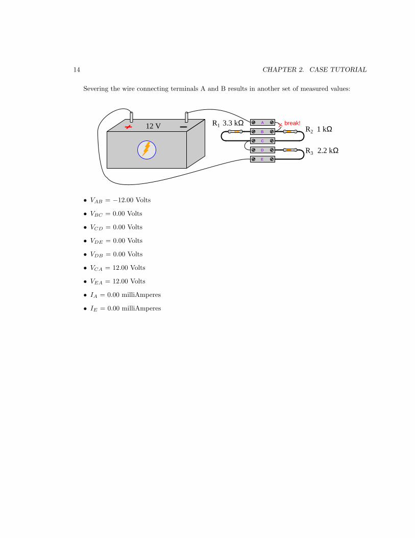
Severing the wire connecting terminals A and B results in another set of measured values:
A
B
C
D
R1R2
R3
3.3 kΩ1 kΩ12 V
E
2.2 kΩ
break!
• VAB = −12.00 Volts
• VBC = 0.00 Volts
• VCD = 0.00 Volts
• VDE = 0.00 Volts
• VDB = 0.00 Volts
• VCA = 12.00 Volts
• VEA = 12.00 Volts
• IA = 0.00 milliAmperes
• IE = 0.00 milliAmperes

2.3. EXAMPLE: CURRENT SOURCE AND FOUR RESISTORS 15
2.3 Example: Current source and four resistors
Here, an electronic current source2, a set of terminal blocks, and several resistors are provided forexperimentation. In this case, the current source is configured to output 150 milliAmperes of current.
Electroniccurrent source
R1 = 47 Ω
R2 = 10 Ω
R3 = 120 Ω
R4 = 63 Ω
A
B
C
D
E
F
G
H
Rather than visually show the placement of test equipment in the diagram, measurements willbe documented in text form as V and I values3. With the circuit constructed as shown in the aboveillustration, we obtain the following measurements:
• VAD = 8.55 Volts
• VEA = −8.55 Volts
• VGE = 0.00 Volts
• VDH = 6.20 Volts
• VGA = −8.55 Volts
• VBC = 0.00 Volts
• VDF = 6.20 Volts
• IA = 150.0 milliAmperes (conventional flow left to right)
• IC = 150.0 milliAmperes (conventional flow left to right)
• ID = 150.0 milliAmperes (conventional flow right to left)
• IH (at resistor lead) = 98.36 milliAmperes (conventional flow right to left)
2Unlike electrochemical batteries which tend to maintain a nearly constant voltage between their terminals over awide range of current values, a current source maintains a nearly constant current over a wide range of voltages.
3Double-lettered subscripts for V denote the placement of voltmeter test leads, with the first and second lettersalways representing the red and black test leads respectively. For example, VBC means the voltage measured betweenterminals B and C with the red test lead touching B and the black test lead touching C. Single-lettered subscripts forV represent the voltmeter’s red test lead, with the black test lead touching a defined “ground” point in the circuit.Current measurements (I) imply measurements made at a single location, and so there will only ever be single-letteredsubscripts for I. Conventional flow notation will be used to specify current direction.

16 CHAPTER 2. CASE TUTORIAL
Severing the wire connecting terminals D and E affects most of the measured values:
Electroniccurrent source
R1 = 47 Ω
R2 = 10 Ω
R3 = 120 Ω
R4 = 63 Ω
A
B
C
D
E
F
G
H
break!
• VAD = 0.00 Volts
• VEA = − (Maximum) Volts
• VGE = 0.00 Volts
• VDH = + (Maximum) Volts
• VGA = − (Maximum) Volts
• VBC = 0.00 Volts
• VDF = + (Maximum) Volts
• IA = 0.00 milliAmperes
• IC = 0.00 milliAmperes
• ID = 0.00 milliAmperes
• IH (at resistor lead) = 0.00 milliAmperes
Note: “Maximum” voltage refers to the compliance voltage of the electronic current source: themaximum amount of voltage it is able to muster between its terminals when faced with an opencircuit. For most electronic current sources, this will be some modest limit such as 15 Volts or 30Volts. However, for some high-energy current sources such as current transformers used in electricpower systems, the maximum open-circuit voltage could actually reach hazardous levels: hundreds
or even thousands of Volts!

Chapter 3
Simplified Tutorial
A series-parallel circuit is one containing both series and parallel networks. A “series” network isdefined by its components being connected in such a way as to form a single path for current (i.e. allcomponents connected in a row). A “parallel” component is defined by its components sharing thesame two sets of electrically common points. Both network types are shown here for comparison:
Series-connected components
Only one path exists for current
Parallel-connected componentsThese points are electrically common
These points are electrically common
A universal property of series networks is that their components share the same
amount of continuous current. This is due to the Law of Electric Charge Conservation: electriccharge carriers can neither be created nor destroyed, but must always be accounted. The only wayfor the amount of current entering any point to differ from the amount of current exiting that samepoint is if charges were to somehow either vanish or come into existence at that point. Since a seriescircuit is nothing more than a back-to-back collection of points, this principle extends to the seriescircuit in its entirety.
A universal property of parallel networks is that their components share the same
amount of voltage. This is due to the Law of Energy Conservation: energy can neither be creatednor destroyed, but must always be accounted. The electrical commonality between connectedterminals of parallel components ensures those connected points form equipotential surfaces. Bydefinition, charge carriers are free to move along a set of equipotential points without gaining orlosing any energy, and therefore any difference in energy between a charge at any point along thatequipotential surface and an identical charge at any point along a different equipotential surfacemust be the same.
A common application of these guarantees is in the connection of electrical meters to measurecurrent and voltage. If we desire to measure current through some component, we must connect ourammeter in series with that component to ensure the meter experiences the exact same current as
17

18 CHAPTER 3. SIMPLIFIED TUTORIAL
the component. Likewise, if we desire to measure voltage across some component, we must connectour voltmeter in parallel with that component to ensure the meter experiences the same voltage asthe component.
For any network operating under continuous (i.e. steady-state)1 conditions, be it series, parallel,or a combination of series and parallel, the total power dissipated by the circuit must be equal to thesum of the individual component power dissipations. This is due to the Law of Energy Conservationas well: the continuous flow of energy into any system must equal the continuous flow of energy outof any system.
Kirchhoff’s Laws of voltage and current are important principles for analyzing series-parallelcircuits as well. Kirchhoff’s Voltage Law (KVL) states that the algebraic sum of all voltage risesand drops in any loop must be equal to zero. This “loop” may or may not happen to trace anactual path for current in a circuit, as KVL is true regardless of path. KVL is based on the Lawof Energy Conservation: when any “test charge” is moved from location to location and eventuallyback to its starting point, its net energy gain/loss must be zero. This is analogous to a hikerclimbing up and down a mountain, gaining potential energy when climbing and losing potentialenergy when descending: when the hiker returns to their starting altitude, their net total potentialenergy gain/loss will be zero.
The following example shows KVL applied to a loop formed by test points D-E-F-G-D in acircuit. VDE (0 Volts) plus VFE (−6.6 Volts) plus VGF (+10 Volts) plus VDG (−3.4 Volts) equalszero:
+−
A B
C
D
EF
R1
R2
R3
1 kΩ
3.3 kΩ
4.7 kΩ
+−V1
V2 8 V
10 V
G
V Ω
COMA
V Ω
COMA
V Ω
CO
MA
V Ω
CO
MA
V Ω
COM A
V Ω
COM A
V Ω
COM A
V Ω
COMA
Loop D-E-F-G-D
VAG
VGF
VFE
VED
VDC
VCB
VBA
VDG
1The qualification of “steady state” is important to note, because it is actually possible to have temporary conditionsof Pin 6= Pout, such as in circuits containing energy-storing/releasing components such as capacitors, inductors, orsecondary-cell batteries.

19
Kirchhoff’s Current Law (KCL) states that the algebraic sum of all currents entering and exitinga point (node) in a circuit must be equal to zero. KCL is based on the Law of Electric ChargeConservation: all charges entering must eventually exit.
The following example shows KCL applied to a node in a circuit. By convention, currentsentering a node are positive and currents exiting a node are negative, and the ammeter connectionsare oriented to reflect this standard. I1 (+18 milliAmperes) plus I2 (−6 milliAmperes) plus I3 (−12milliAmperes) equals zero:
+ −
PointI3
I1 I2
R1
R2V1
12 V
1 kΩ
2 kΩ
V Ω
COMA
V Ω
COM A
V Ω
CO
MA
mA
mA
mA

20 CHAPTER 3. SIMPLIFIED TUTORIAL
Mastery of these concepts is foundational to successful series-parallel circuit analysis, whichconsists of representing every series and parallel resistance sub-network in a circuit as equivalentresistances, then repeating this process until the circuit is reduced to a single equivalent resistance.This basic strategy is shown in the following illustration, showing how a five-component series-parallel circuit may be reduced to a single equivalent component in a succession of reducing steps:
1
2 3
4 5S
1
S
S
4||5
2--3
Series
ParallelParallel
1||(2--3)
4||5S
[1||(2--3)]--[4||5]
Series
Reducing a series-parallel networkone sub-network at a time
Single equivalent component
The same reduction process is applied to multiple sources, if they exist in the circuit too. Atthat point, Ohm’s Law may be applied to that single equivalent resistance and to the single sourceto calculate either voltage or current. Once that is done, the equivalent circuit may be “expanded”step-by-step, transferring all voltage and current values from the simpler version as the propertiesof series and parallel networks dictate, re-applying various laws (Ohm’s, KVL, KCL) as needed tocalculate any unknown voltages or currents. When complete, the all voltages and currents in thecircuit’s original form should be known.
An excellent habit to develop when solving any problem is to check your work, with the variousproperties and laws you’ve learned about circuits being great tools for this purpose. For example,after “collapsing” and then “expanding” a series-parallel circuit to calculate all component voltagesand currents, it is a good idea to apply KVL and KCL to the final result as a check of your work:no matter where you apply KVL and/or KCL, all the final results for voltage and current shouldcorrectly check.

21
Series-parallel networks consisting of identical components are relatively easy to analyze. Seriesnetworks of identical components exhibit a total resistance equal to one component’s resistance timesthe number of components; identical sources connected in series (aiding) yield a total voltage equal toone source’s voltage times the number of sources. Likewise, parallel networks of identical componentsexhibit a total resistance equal to one component’s resistance divided by the number of components;identical sources connected in parallel (aiding) yield a total current equal to one source’s currenttimes the number of sources. When stacked in a series-parallel fashion, these resistance, voltage, andcurrent values compound the same: stacking parallel sub-networks in series with each other yieldsmore resistance and more voltage; stacking series sub-networks in parallel with each other yields lessresistance and more current.
This “stacking” technique is commonly employed to construct large arrays of energy sources andenergy-storage devices such photovoltaic solar cells and battery banks.
Voltage divider circuits are series networks, and current divider circuits are parallel networks.When any external load component is connected to either type of divider circuit, the output of thatdivider circuit will necessarily decrease as a result of that added load. This is due to the fact thatadding a load to any simple divider circuit transforms that circuit from a simple-series or simple-parallel network into a series-parallel combination network. The resistance of the connected loadcombines with the resistance of the divider component connected to the load terminal(s) to form anew equivalent resistance, and this new equivalent resistance value reduces the division ratio thatexisted prior to the load’s connection.
Connecting a meter to a circuit likewise creates either a series (ammeter) or parallel (voltmeter)sub-network that did not previously exist in the circuit, and “loads” that circuit by extracting asmall amount of energy from it. If this newly-formed network converts what was once a simple seriesor parallel circuit into a series-parallel combination circuit (e.g. connecting a voltmeter in parallelwith one component in a series circuit), the result will be that the meter reads slightly less thanthe true value when unconnected. Voltmeters exhibit very high (but not infinite) resistance, whileammeters exhibit very low (but not zero) resistance, and this means the loading effect should beslight. In either case, the finite resistance of a meter is called its insertion resistance.

22 CHAPTER 3. SIMPLIFIED TUTORIAL

Chapter 4
Full Tutorial
First, a review of foundational circuit principles.
Three fundamental measures of electricity are voltage (V ), current (I), and resistance (R).Voltage is defined as the amount of energy either gained or lost by electric charge carriers betweentwo different locations. Current is defined as the rate of charge carrier flow. Resistance is defined asthe amount of voltage drop (i.e. energy lost per charge carrier) for a given amount of current (flow).Ohm’s Law relates these three variables mathematically:
V = IR I =V
RR =
V
I
The combination of voltage and current is power (P ): the amount of energy either gained orlost per charge carrier multiplied by the number of charge carriers passing through over time equalsthe rate of energy gained or lost over time. Joule’s Law mathematically relates power to voltage,current, and resistance:
P = IV P = I2R P =V 2
R
Electrical components designed to boost the energy level of charge carriers passing through arereferred to as sources. Components extracting energy from passing charge carriers are called loads.The identity of any component as either a source or a load is evident by comparing the voltagepolarity marks versus direction of current. If current enters a component on the “−” side and exitson the “+” side, it means the charge carriers enter at a lower energy level and exit at a higher energylevel, which makes that component a source. If current enters a component on the “+” side andexits on the “−” side, it means the charge carriers enter at a higher energy level and exit at a lowerenergy level, which makes that component a load.
When electrical components are connected together, they form an electrical network. Connectionsbetween electrical components may be broadly divided into two categories: series and parallel.Each of these network types exhibits unique properties, and must be thoroughly understood beforeattempting to understand more complex types of electrical networks.
23

24 CHAPTER 4. FULL TUTORIAL
When electrical components are connected together such that they form a chain providing onlyone path for current, they are said to be connected in series with each other:
Component #1 Component #2 Component #3
wire wire wire wire
I I I I. . . . . .
With only one path for charge carriers to flow through each component, any continuous flowof electric charge carriers (i.e. current, I) through each component must be equal due to the Lawof Electric Charge Conservation (electric charges can neither be created nor destroyed). Similarly,the Law of Energy Conservation – which states that energy can neither be created or destroyed –informs us that the energy gains or losses of electric charge carriers moving through each componentaccumulate to equal the total gain or loss in energy for the series network; that is to say, voltagesacross a set of series-connected components algebraically add to equal the series network’s totalvoltage. For the same reason, the total resistance (R) of a series network (defined as the amountof energy lost per charge carrier for a given rate of flow) is equal to the sum of all the individualcomponent and wire resistances. Mathematically stating each of these series network properties:
Itotal = I1 = I2 · · · = In
Vtotal = V1 + V2 · · · + Vn
Rtotal = R1 + R2 · · · + Rn
Series connections are used in the measurement of electric current, to ensure the instrumentdesigned to measure electric current (an ammeter) will sense the exact same amount of current asthe component being tested. A series connection between an ammeter and the component undertest guarantees this equality of current:
I II
I. . . . . .A
Ammeter connected in series, so as to experiencethe exact same current as the other components
Note that multiple locations are possible for the ammeter – any location that is in-line with allcomponents will yield the same measurement of current which is the value of current common to allcomponents in this series network.

25
When electrical components are connected together such that they share the same two setsof electrically common points (i.e. their respective terminals are made equipotential by directconnection), they are said to be connected in parallel with each other:
Component #1
Component #2
Component #3
wire. . . . . .
wire
V
V
V
electrically common electrically common
The term equipotential means no energy is lost or gained by electric charge carriers movingbetween those connected points. Points connected together by a conductor of negligible resistancewill be equipotential by virtue of that conductor’s low resistance. In the parallel network shownabove, charge carriers on all the left-hand wires of the network exist at the same potential energylevel, as do charge carriers on all the right-hand wires. Therefore, any difference of potentialbetween the left and right wires must be the same. Therefore every component in a parallel networkexperiences the same potential difference (i.e. same voltage, V ). In this example, any chargecarriers moving from left to right through any of the components will lose the same amount ofenergy, regardless of which component they happen to pass through.
Current values through each component in a parallel network, however, may differ substantially.In fact, Ohm’s Law (I = V
R) guarantees this will be the case if the components in question happen
to have differing resistance values (R) but all share the same voltage value (V ). Given the Law ofCharge Conservation, we may conclude that the total current for a parallel network must be equalto the algebraic sum of all component (“branch”) currents. Another property of parallel networks isthat their total resistance is less than that of the lowest-resistance branch. Mathematically statingeach of these parallel network properties:
Vtotal = V1 = V2 · · · = Vn
Itotal = I1 + I2 · · · + In
Rtotal =1
1R1
+ 1R2
· · · + 1Rn
Parallel connections are used in the measurement of voltage, to ensure the instrument designedto measure voltage (a voltmeter) will sense the exact same amount of voltage as the componentbeing tested. A parallel connection between a voltmeter and the component under test guaranteesthis equality of voltage.

26 CHAPTER 4. FULL TUTORIAL
wire. . . . . .
wire
V
V
V
VV
Voltmeter connected in parallel,so as to experience the exactsame voltage as the othercomponents
electrically common electrically common
Note that multiple locations are possible for the voltmeter – touching the voltmeter’s left-handtest lead to any point on the left-hand equipotential zone, and touching the voltmeter’s right-handtest lead to any point on the right-hand equipotential zone, will yield the same measurement ofvoltage which is the value of voltage common to all components in this parallel network.
A property common to all networks, series and parallel alike, is that total (i.e. source) poweris equal to the sum of all load powers in a circuit. This is just an extension of the Law of EnergyConservation (that energy cannot be created or destroyed and so must be accounted for in all cases),because power is nothing more than energy transfer per unit time:
Ptotal = P1 + P2 · · · + Pn
This holds true for all circuits operating under steady-state1 conditions, regardless of shape,because the Law of Energy Conservation is universal.
1By “steady-state” we mean the quantities of voltage, current, and power remain constant over substantial periodsof time. This caveat is based on the fact that energy is always and forever conserved, but power is not necessarilyso. Imagine a scenario where a weight is slowly hoisted up to some elevation, and then released so that it falls tothe ground: the amount of energy invested in the weight’s ascent is exactly equal to the amount of energy releasedby the weight as it falls (in the forms of air friction heating, and also energy delivered to the ground upon impact).However, the amount of power expended in slowly hoisting the weight far less than the amount of power deliveredby the weight as it slams into the ground, simply due to the disparity in time intervals: the former happens over along time interval, while the latter occurs over a very brief time interval. An analogous electrical scenario is that ofa capacitor slowly energizing to some high voltage level, then rapidly de-energizing into a low-resistance load: theamount of energy invested in the capacitor is precisely equal to the amount of energy later delivered to that load,but the rates of power are quite unequal due to the timespan over which each action takes place. So, when analyzingany circuit operating under steady-state conditions we may regard power as a conserved quantity because everythingoccurs over the same span of time, but know that it is really energy that is conserved. If the circuit does not operateunder steady-state conditions, source power and load power may in fact differ greatly.

27
Kirchhoff’s Voltage Law (KVL) states that the net change in energy for any charge movedaround in a loop – i.e. moved from point to point, returning to the same location where it started– will always be zero. That is to say, as an electric charge gains and loses energy moving betweenthese different points, it must always return to its original energy level after returning to its originallocation. Since energy gains and losses for electric charges is the definition of voltage, we may expressKVL by saying that the algebraic sum of all voltages in a loop equals zero.
If we label points within a loop by letter (e.g. A, B, C, etc.) and denote each voltage within thatloop by a letter subscript pair (e.g. VXY , the amount of energy gained or lost by a charge movingfrom Y to X), KVL becomes evident just by the subscripts. If we move a “test charge” from point Ato point B and note the voltage (VBA), then from point B to point C (VCB), then all the way aroundthe loop until we return to point A, the sum of those voltages must be the same as the amount ofvoltage moving from point A to point A (VAA) – i.e. the amount of voltage between identical points.Of course, this must be equal to zero:
VBA + VCB + VnC · · · + VAn = VAA = 0
KVL is true regardless of the path taken by the charge, as it is an expression of the Law ofEnergy Conservation (i.e. that energy cannot be created or destroyed, and therefore the amount ofenergy carried by an electric charge cannot simply appear or vanish, but must be accounted for inevery step of that charge’s travels). The path traced need not be in the direction of real current inthe circuit, and in fact need not follow any circuit conductors at all. It is perfectly permissible totrace a KVL loop that “jumps” between disconnected points in a circuit. In fact, this is what weoften do when applying KVL to the calculation of voltage between points not directly spanned byone component.
Kirchhoff’s Voltage Law (KVL) is useful for calculating unknown voltage values between pointsin a circuit, if all the other voltage values between points in a loop happen to be known.
Kirchhoff’s Current Law (KCL) states that charge carriers entering a point must exit that point,which is a consequence of the Law of Electric Charge Conservation (i.e. that electric charges cannotbe created or destroyed, but must be accounted for in all cases). That is to say, the total amount ofcurrent entering a point (or “node”) in a circuit must be the same as the total amount of currentexiting that same point. This is true regardless of the number of conductive paths connecting atthat point. We may express KCL by saying that the algebraic sum of all currents at a node equalszero:
I1 + I2 + I3 · · · + In = 0
Kirchhoff’s Current Law (KCL) is useful for calculating unknown currents in a circuit, if all theother currents entering and/or exiting a points in the circuit happen to be known.

28 CHAPTER 4. FULL TUTORIAL
Now that we have reviewed series and parallel circuits, as well as Kirchhoff’s Laws, let us moveon to the topic at hand: series-parallel circuits. As the name implies, these circuits are a blend ofseries and parallel sections. Consider the following four-resistor circuit which is neither purely seriesnor purely parallel:
+−
R1
V1
R2
R3
R4
10 V
1.2 kΩ
2.7 kΩ
2.2 kΩ
790 Ω
Original circuit:
An effective method for analyzing any series-parallel resistor circuit consists of applying theprinciples of series networks and of parallel networks to those portions of the circuit that are2 seriesand parallel, respectively, then using the results of those analyses to derive an equivalent of theoriginal circuit using fewer resistors. This process is repeated until the circuit has been condensedto a single resistor representing that circuit’s total resistance. Series and parallel connections willbe represented in text form by the symbols ↔ (series) and ‖ (parallel).
After condensing the original resistor network down to a single equivalent resistor, we may applyOhm’s Law to the calculation of current and/or voltage (depending on the nature of the source).Once those values have been determined, we may “expand” the single-resistor circuit back to itsprevious equivalent and apply those calculated values there. After that, we apply Ohm’s Law againto the calculation of voltage and/or current and then transfer those values to the next “expansion”of the circuit and so on until we arrive back at the original circuit configuration with all voltagesand currents solved.
If this process sounds tedious to you, know that it certainly can be. However, there are worseproblems in life than tedium. Unsolvable problems are certainly worse, and that is what this series-parallel circuit certainly appears to be without analyzing it stage by stage. You should know thata great many analytical problem-solving techniques are nothing more than substitutions of tedium
for complexity. By methodically analyzing this series-parallel circuit one sub-network at a time, weexchange its original complexity for a long sequence of relatively simple steps, and that makes itsolvable. Effective problem-solvers are patient above all else!
2While this problem-solving technique is presented here specifically for series-parallel resistor circuits, it is anexpression of a more general problem-solving strategy: solve what you can. A common tendency of students new toany analytical subject is to give up when presented with a problem that they don’t see a complete solution for fromthe start. Instead, what one should do when presented with a complicated problem is begin by solving what you do
know how, even if it is not clear to you how that solution might help you attain a final solution to the problem athand. As you will see here, applying simple series and simple parallel analysis to portions of the original circuit hasthe effect of simplifying that circuit, and so with each step the original problem becomes less and less daunting.

29
We will begin our analysis of this series-parallel circuit by noting which sections (i.e. sub-networks) of it are series and which are parallel, if any3. Here we see that R1 and R2 are connectedin parallel with each other, as are R3 and R4. Knowing that parallel-connected resistances result ina diminished total resistance according to the formula Rparallel = (R−1
1 +R−12 )−1, we may calculate
the equivalent resistance value for R1 ‖ R2 and for R3 ‖ R4:
(R1 ‖ R2) =1
11200 Ω + 1
2700 Ω
= 830.77 Ω
(R3 ‖ R4) =1
12200 Ω + 1
790 Ω
= 581.27 Ω
+−V1
10 V
R1 || R2 R3 || R4
581.27 Ω830.77 Ω
Parallel equivalents:
Once we re-draw the circuit to show each of the parallel sub-networks as single equivalentresistances, the circuit now appears to be a simple series network, much simpler to analyze thanbefore. It should come as no surprise that we should be able to apply this same technique again:identify portions of the circuit that are either simply series or simply parallel and reduce thosesub-networks to single equivalent resistors.
3It is imperative that you have a solid grasp on the definitions of series and parallel networks, so that you may readilyrecognize series-connected and parallel-connected components within a larger network. Recall that the definition of aseries network is one where only a single path exists for current, and that the definition of a parallel network is onewhere the components connect between the same two points.

30 CHAPTER 4. FULL TUTORIAL
Reducing it one more step, knowing that series-connected resistances result in an additive totalaccording to the formula Rseries = R1 + R2:
R(R1‖R2)↔(R3‖R4) = 830.77 Ω + 581.27 Ω = 1412.04 Ω
+−
V1
10 V
(R1 || R2) ↔ (R3 || R4)
1412.04 Ω
Series equivalent:
This single-resistor circuit is obviously not identical to the original four-resistor circuit, but it isequivalent in terms of total resistance. And, if the total resistance is the same, then the total currentpredicted by Ohm’s Law must be the same as well:
Itotal =V1
Rtotal
=10 V
1412.04 Ω= 7.082 mA
It is always a good idea during circuit analysis to annotate your schematic diagrams withcalculated values, to provide clear context for those numerical values. Here, we will sketch anarrow showing the calculated total current value of 7.082 mA as well as the 10 Volts impressedacross the single equivalent resistor:
+−
V1
10 V
(R1 || R2) ↔ (R3 || R4)
1412.04 Ω
Series equivalent:
7.082 mA
10 V

31
Now, working our way back to the original circuit configuration, we will examine the equivalentcircuit prior to this one to see which values transfer. The previous equivalent circuit was a series
configuration, and we know that it is current which is shared among series-connected components.Therefore, it is the 7.082 mA current value we just calculated that may be applied to the previousequivalent circuit:
+−
V1
10 V
R1 || R2 R3 || R4
581.27 Ω830.77 Ω
Parallel equivalents:
7.082 mA
Ohm’s Law may be applied here to calculate the voltage dropped by each of the two equivalentresistors:
VR1‖R2= I(R1 ‖ R2) = (7.082 mA)(830.77 Ω) = 5.883 V
VR3‖R4= I(R3 ‖ R4) = (7.082 mA)(581.27 Ω) = 4.117 V
Annotating our diagram with these values:
+−
V1
10 V
R1 || R2 R3 || R4
581.27 Ω830.77 Ω
Parallel equivalents:
7.082 mA
4.117 V5.883 V

32 CHAPTER 4. FULL TUTORIAL
Still working our way back to the original circuit configuration, we examine it to see which of thecalculated values from this last analysis will transfer. The original circuit (just one step removedfrom the last equivalent circuit shown) is a parallel expansion of this circuit’s two resistances. Weknow that it is voltage which is shared among parallel-connected components, and so we will transferthe 5.883 Volt and 4.117 Volt values to the original circuit:
+−
R1
V1
R2
R3
R4
10 V
1.2 kΩ
2.7 kΩ
2.2 kΩ
790 Ω
Original circuit:
5.883 V 4.117 V
5.883 V 4.117 V
7.082 mA
Ohm’s Law may be applied again, this time to calculate current through each individual resistor.Note how we are careful to keep all values in proper context4 with each other, calculating the currentthrough each resistor by dividing that resistor’s voltage by that resistor’s resistance:
IR1 =VR1
R1=
5.883 V
1200 Ω= 4.903 mA
IR2 =VR2
R2=
5.883 V
2700 Ω= 2.179 mA
IR3 =VR3
R3=
4.117 V
2200 Ω= 1.871 mA
IR4 =VR4
R4=
4.117 V
790 Ω= 5.211 mA
4Mixing contexts is a common way in which students fail to calculate correct results when applying mathematicalformulae to physical problems. It is imperative you understand what each and every numerical value means in acircuit, and where it fits. This is the main reason I recommend annotating schematic diagrams with calculated values:to help remind you of those values’ contexts.

33
Annotating the original schematic diagram with all current values:
+−
R1
V1
R2
R3
R4
10 V
1.2 kΩ
2.7 kΩ
2.2 kΩ
790 Ω
Original circuit:
5.883 V 4.117 V
5.883 V 4.117 V
4.903 mA
2.179 mA
7.082 mA
1.871 mA
5.211 mA
A wise habit to adopt is checking your solutions, and that is best done by analyzing the resultsin a different manner than the one by which they were obtained5. In this case, our calculated valuesconsist of resistor voltage drops and resistor currents. In order to rigorously check these values, weneed to apply some principles using voltages and currents other than Ohm’s Law.
Kirchhoff’s Laws provide an excellent means of checking these solutions. We know fromKirchhoff’s Voltage Law (KVL) that the algebraic sum of all voltages in a loop must equal zero.Applying KVL to our analysis by imagining a “test charge” starting at the left-hand conductor ofthe circuit and progressing around it in a counter-clockwise direction, we will check to see that allthe potential gains and losses indeed sum to zero:
(+5.883 V) + (+4.117 V) + (−10 V) = 0 V
We know from Kirchhoff’s Current Law (KCL) that the algebraic sum of all currents enteringand exiting a node must equal zero. Applying KCL to any of the nodes at the parallel sub-networks,for example at the right-hand node of R1 ‖ R2 where 7.082 mA enters, 4.903 mA exits, and 2.179mA also exits:
(+7.082 mA) + (−4.903 mA) + (−2.179 mA) = 0 mA
The only analysis left to do at this point is calculate resistor power dissipations, and that may be
done in three different ways (P = IV , P = I2R, or P = V 2
R). For this example I will leave this as an
exercise for the reader. Once all resistor power dissipations are calculated, they may be checked bycalculating source power (P = 7.082 mA × 10 V) and verifying that the sum of all resistor powersequals this source power, according to the Conservation of Energy.
5The novice may see nothing wrong with repeating a set of calculations to ensure none of them were incorrectlycomputed. However, this naturally leads to a repeat of the same mistakes, if there were any mistakes made. Whenthe checking is done by some means other than the one taken to obtain the original results, common mistakes suchas calculator keystroke errors, procedural errors, and other errors prone to repetition are avoided.

34 CHAPTER 4. FULL TUTORIAL
Let us analyze a more complex series-parallel circuit in order to see how these same principlesmay be applied. In this analysis I will omit detailed explanations of every step, and just show thecircuit being condensed step-by-step into a single-source and single-resistor equivalent, then expandit step-by-step back to its original form. Each schematic diagram will be fully annotated to showthe context of all calculated values.
Here is the original circuit, consisting of two voltage sources and six resistors:
+−
+ −
R1
R2
R3
R4
R5
R6V1
V2
150 Ω
220 Ω
100 Ω
330 Ω
130 Ω
470 Ω9 V
5 V
It should be evident that R1 and R2 are in parallel with each other, and R4 and R5 are in serieswith each other.

35
First equivalent circuit, condensing resistors R1 and R2 into a parallel equivalent, and resistors R4
and R5 into a series equivalent:
+−
+ −
R3
R6V1
V2
150 Ω
470 Ω9 V
5 V
R1 || R2
68.75 Ω
R4 ↔ R5 460 Ω
Now we see that R4 ↔ R5 is in parallel with R6.

36 CHAPTER 4. FULL TUTORIAL
Second equivalent circuit, condensing resistors R4, R5, and R6 into a single equivalent:
+−
+ −
R3
V1
V2
150 Ω
9 V
5 V
R1 || R2
68.75 Ω
(R4 ↔ R5) || R6 232.47 Ω
Now it is clear to see that all components are in series with each other, because there is only onepath for current between them all. This means we may condense the three resistors into a singleequivalent resistor, and the two sources into a single equivalent source.
Our final equivalent circuit will condense all resistors into a single equivalent and both voltage sourcesinto a single source. The two voltage sources are opposing each other, and so the combination of themwill be a single source with the stronger source’s polarity and a magnitude equal to the differencein voltage between the two original sources:
+−
4 VV1 ↔ V2
R3 ↔ [(R4 ↔ R5) || R6] ↔ (R1 || R2)451.22 Ω
At this point we are ready to apply Ohm’s Law to the calculation of current, and later to thecalculation of individual resistor voltages and currents.
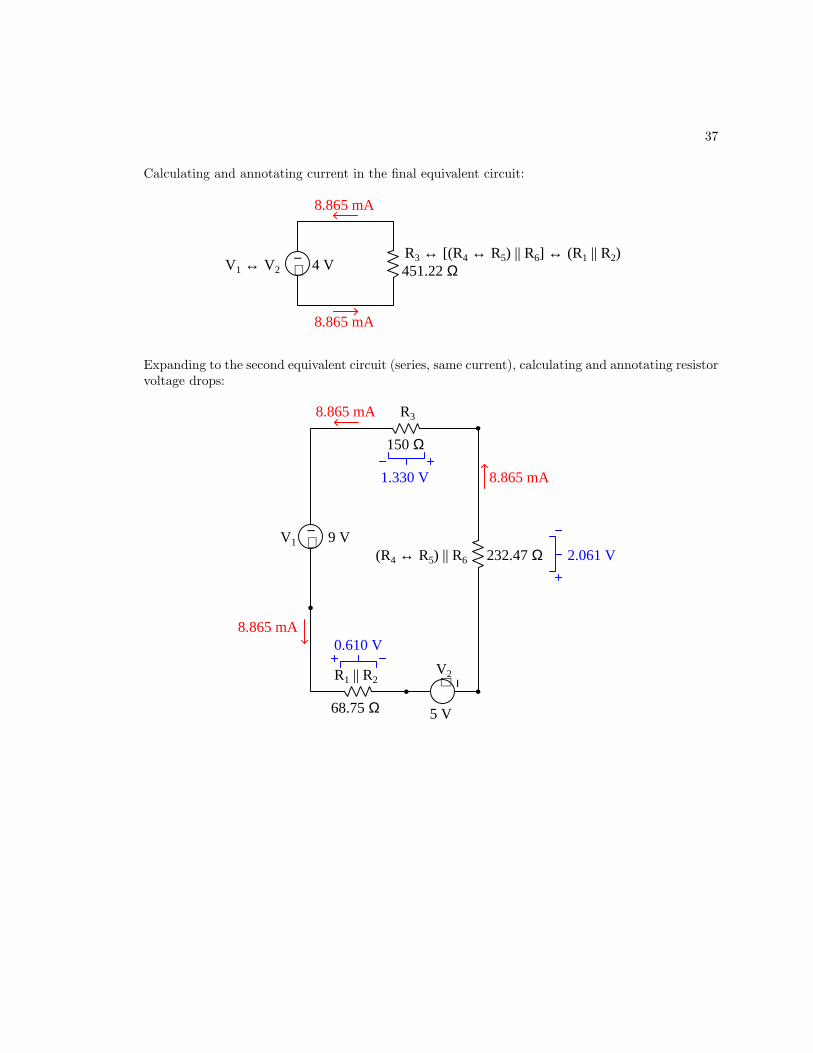
37
Calculating and annotating current in the final equivalent circuit:
+−
4 VV1 ↔ V2
R3 ↔ [(R4 ↔ R5) || R6] ↔ (R1 || R2)451.22 Ω
8.865 mA
8.865 mA
Expanding to the second equivalent circuit (series, same current), calculating and annotating resistorvoltage drops:
+−
+ −
R3
V1
V2
150 Ω
9 V
5 V
R1 || R2
68.75 Ω
(R4 ↔ R5) || R6 232.47 Ω
8.865 mA
8.865 mA
8.865 mA
1.330 V
2.061 V
0.610 V
38 CHAPTER 4. FULL TUTORIAL
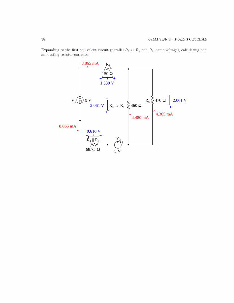
Expanding to the first equivalent circuit (parallel R4 ↔ R5 and R6, same voltage), calculating andannotating resistor currents:
+−
+ −
R3
R6V1
V2
150 Ω
470 Ω9 V
5 V
R1 || R2
68.75 Ω
R4 ↔ R5 460 Ω
8.865 mA
1.330 V
2.061 V2.061 V
4.385 mA
8.865 mA
4.480 mA
0.610 V

39
Expanding to the original circuit, calculating and annotating resistor currents:
+−
+ −
R3
R6V1
V2
150 Ω
470 Ω9 V
5 V
R4 ↔ R5 460 Ω
8.865 mA
1.330 V
2.061 V2.061 V
4.385 mA8.865 mA
4.480 mA
100 Ω
R2
R1
220 Ω
6.095 mA
2.770 mA
0.610 V
As usual, KVL and KCL offer ways for us to check6 our work. Here, we may apply KVL to theouter-most loop of the circuit beginning at the upper-left corner and proceeding counter-clockwise.KCL will be applied at both the node below the 9 Volt source and the node to the right of R3.Where and how we apply Kirchhoff’s Laws really doesn’t matter, so long as our application verifiesall calculated values of voltage and current:
KVL, outer loop: (+9 V) + (−0.610 V) + (−5 V) + (−2.061 V) + (−1.330 V) = 0 V
KCL @ V1 node: (8.865 mA) + (−2.770 mA) + (−6.095 mA) = 0 mA
KCL @ R3 node: (4.480 mA) + (4.385 mA) + (−8.865 mA) = 0 mA
Resistor power dissipations may be calculated by applying Joule’s Law in any manner desired
(P = IV , P = I2R, and/or P = V 2
R). As a final check, the sum of all resistor power values must
equal the total source power (treating the two sources as a single7 4 Volt source carrying 8.865mA) because the Conservation of Energy in any steady-state scenario means that power must beconserved as well.
6You will notice that the voltage values shown in the KVL check don’t exact add up to zero, but that is dueto rounding. If these voltage values are retained in your calculator’s memory rather than written and re-typed intruncated form, the sum ends up being exactly equal to zero as it should be.
7Alternatively, one could calculate power sourced by V1 and treat V2 as a load, since you will note current is beingforced “backward” through V2.

40 CHAPTER 4. FULL TUTORIAL
Some series-parallel networks are much easier to analyze than the examples previously given. Ifall components in the series and parallel sub-networks are equal in value, the task of calculatingequivalent components in the condensed versions of the circuit becomes almost trivial. Take forinstance this series-parallel network of batteries for an energy-storage system:
If each of the batteries outputs 12.6 Volts, and each one has a maximum output current of 35Amperes, then the array as a whole outputs 37.8 Volts (12.6 Volts times three in series) and maydeliver up to 175 Amperes of current to a load (35 Amperes times five in parallel).
A series-parallel resistor “bank” comprised of identical resistors likewise condenses very easilyinto a single equivalent resistance:
If each of these resistors is rated at 100 Ω and 2 Watts, then the combination of three in seriesyields 300 Ω for each parallel branch, and the combination of four parallel branches diminishesthat by a factor of four for a total of 75 Ω. Power ratings simply add up to a total of 24 Watts(12 resistors times 2 Watts each), regardless of the series-parallel configuration, due to the Law ofEnergy Conservation which stands regardless of circuit shape.

41
Series-parallel networks may be formed when new components are connected to existing (series-or parallel-only) circuits. One such example is that of loaded voltage divider circuits. As you recall,a “voltage divider” is a network of series-connected resistors intended to divide an applied voltageinto smaller proportions. A common application for voltage dividers is to reduce the voltage from asource, down to some level more suitable for a load. A problem faced with such usage of a voltagedivider is that once the load is connected to the divider circuit, its voltage division ratio changes byvirtue of the load creating a series-parallel network where only a series network existed before.
Take the following voltage divider as an example. With no load connected, its two resistorsdivide the source voltage into two-thirds and one-third portion, with the lowest third constitutingthe “output” of the voltage divider. Once a load is connected to the output terminal, though, theoutput voltage “sags” to a value less than the desired 1
3 proportion under the loading effect:
+−24 V
Voltage divider
8 V
(Unloaded) (Loaded)
22 kΩ 6.14 V10 kΩ
20 kΩ
Voltage divider
10 kΩ
20 kΩ
+−24 V
Vout Vout
Rload
Perfect 1:3 ratio
If this voltage divider network is to provide a precise 13 voltage-division ratio to a load, its resistor
values must be selected in anticipation of that load resistance. Only then will the division ratio becorrect for the series-parallel network that is formed when the load is attached.
Applying this design strategy to the voltage divider just shown, we could replace the 20 kΩresistor with a lower-valued resistor, equal to twice the resistance of the 10 kΩ ‖ Rload parallel sub-
network. When calculated, 2(
(10 kΩ)−1 + (20 kΩ)−1)−1
= 13.75 kΩ. With this new upper resistorin place, the voltage divider will supply the desired 1
3 ratio (8 Volts from a 24 Volt source) whenloaded, but of course will output more than that when unloaded:
+−24 V
Voltage divider(Unloaded) (Loaded)
22 kΩ10 kΩ
Voltage divider
10 kΩ
+−24 V
Vout Vout
Rload
13.75 kΩ 13.75 kΩ
8 V10.11 V
Perfect 1:3 ratio
It should be noted that the re-designed voltage divider only provides the 13 voltage division ratio
when the load resistance is precisely 22 kΩ. A new load resistance will require another re-design.
Current divider circuits face similar challenges maintaining a desired division ratio when loaded.Just as with voltage dividers, the addition of a load resistance converts what was once a simple(series or parallel) network into a more complex series-parallel network.

42 CHAPTER 4. FULL TUTORIAL
This same “loading” problem can occur simply by connecting a meter to a circuit to measurevoltage or current. Recall that an ideal voltmeter possesses infinite internal resistance, and thatan ideal ammeter possesses zero internal resistance. The purpose of these ideal resistance valuesis to minimize the amount of energy extracted from the circuit by the meter, because extractingenergy alters the operation of the circuit and will yield a measured value different than the truevalue with the meter absent. In practice it is impossible to measure any quantity without affectingthat quantity in any way, but we can minimize the impact any measurement of ours may have.
For example, a voltmeter should have infinite resistance so that no current will pass through itwhile sensing a voltage. If no charge carriers pass through a voltmeter, none of them will move froma position of higher energy to a position of lower energy, which means no energy will be released bycharge carriers to the voltmeter – the voltmeter will simply sense the potential between two pointswithout actually converting any of that potential energy into work.
Likewise, an ammeter should have zero resistance so that current passing through it will not dropany voltage. If no voltage drop occurs, it means charge carriers will have passed through withoutlosing any of their energy – the ammeter will simply sense the flow of charge carriers without forcingthem to do any work.
Real voltmeters and ammeters, though, possess finite amounts of resistance called insertion
resistance. Digital multimeters in voltage-sensing mode typically exhibit millions of Ohms betweentheir test leads, and DMMs in current-sensing mode typically exhibit just a small fraction ofone Ohm. The following resistor network (source omitted) shows the expected loading effects ofconnected meters:
. . . . . .
R1
R2
R3 R4
R5
R6
OFF
COMA
V A
V A
OFF
COMA
V A
V A
Ivoltmeter
Vammeter
VR3↔R4 is less than normalwith the voltmeter connected
IR2 is less than normalwith the ammeter connected
Rvoltmeter ≈ MΩ
Rammeter < 1 Ω
The voltmeter connected in parallel with R3 ↔ R4 forms a new series-parallel sub-network,Rvoltmeter ‖ (R3 ↔ R4) having slightly less resistance and therefore dropping slightly less voltagethan R3 ↔ R4 would on their own. The ammeter connected in series with R2 forms a new series-parallel sub-network, R1 ‖ (R2 ↔) having slightly greater resistance in the R2 branch which divertsmore current through R1 and therefore passes slightly less current than R2 would on its own. Ineither case, the meter’s loading effect results in a measurement that is falsely low.

Chapter 5
Programming References
A powerful tool for mathematical modeling is text-based computer programming. This is whereyou type coded commands in text form which the computer is able to interpret. Many differenttext-based languages exist for this purpose, but we will focus here on just two of them, C++ andPython.
43

44 CHAPTER 5. PROGRAMMING REFERENCES
5.1 Programming in C++
One of the more popular text-based computer programming languages is called C++. This is acompiled language, which means you must create a plain-text file containing C++ code using aprogram called a text editor, then execute a software application called a compiler to translate your“source code” into instructions directly understandable to the computer. Here is an example of“source code” for a very simple C++ program intended to perform some basic arithmetic operationsand print the results to the computer’s console:
#include <iostream>
using namespace std;
int main (void)
float x, y;
x = 200;
y = -560.5;
cout << "This simple program performs basic arithmetic on" << endl;
cout << "the two numbers " << x << " and " << y << " and then" << endl;
cout << "displays the results on the computer’s console." << endl;
cout << endl;
cout << "Sum = " << x + y << endl;
cout << "Difference = " << x - y << endl;
cout << "Product = " << x * y << endl;
cout << "Quotient of " << x / y << endl;
return 0;
Computer languages such as C++ are designed to make sense when read by human programmers.The general order of execution is left-to-right, top-to-bottom just the same as reading any textdocument written in English. Blank lines, indentation, and other “whitespace” is largely irrelevantin C++ code, and is included only to make the code more pleasing1 to view.
1Although not included in this example, comments preceded by double-forward slash characters (//) may be addedto source code as well to provide explanations of what the code is supposed to do, for the benefit of anyone readingit. The compiler application will ignore all comments.

5.1. PROGRAMMING IN C++ 45
Let’s examine the C++ source code to explain what it means:
• #include <iostream> and using namespace std; are set-up instructions to the compilergiving it some context in which to interpret your code. The code specific to your task is locatedbetween the brace symbols ( and , often referred to as “curly-braces”).
• int main (void) labels the “Main” function for the computer: the instructions within thisfunction (lying between the and symbols) it will be commanded to execute. Every completeC++ program contains a main function at minimum, and often additional functions as well,but the main function is where execution always begins. The int declares this function willreturn an integer number value when complete, which helps to explain the purpose of thereturn 0; statement at the end of the main function: providing a numerical value of zero atthe program’s completion as promised by int. This returned value is rather incidental to ourpurpose here, but it is fairly standard practice in C++ programming.
• Grouping symbols such as (parentheses) and braces abound in C, C++, and other languages(e.g. Java). Parentheses typically group data to be processed by a function, called arguments
to that function. Braces surround lines of executable code belonging to a particular function.
• The float declaration reserves places in the computer’s memory for two floating-point
variables, in this case the variables’ names being x and y. In most text-based programminglanguages, variables may be named by single letters or by combinations of letters (e.g. xyz
would be a single variable).
• The next two lines assign numerical values to the two variables. Note how each line terminateswith a semicolon character (;) and how this pattern holds true for most of the lines in thisprogram. In C++ semicolons are analogous to periods at the ends of English sentences. Thisdemarcation of each line’s end is necessary because C++ ignores whitespace on the page anddoesn’t “know” otherwise where one line ends and another begins.
• All the other instructions take the form of a cout command which prints characters tothe “standard output” stream of the computer, which in this case will be text displayedon the console. The double-less-than symbols (<<) show data being sent toward the cout
command. Note how verbatim text is enclosed in quotation marks, while variables such as x
or mathematical expressions such as x - y are not enclosed in quotations because we wantthe computer to display the numerical values represented, not the literal text.
• Standard arithmetic operations (add, subtract, multiply, divide) are represented as +, -, *,and /, respectively.
• The endl found at the end of every cout statement marks the end of a line of text printedto the computer’s console display. If not for these endl inclusions, the displayed text wouldresemble a run-on sentence rather than a paragraph. Note the cout << endl; line, whichdoes nothing but create a blank line on the screen, for no reason other than esthetics.

46 CHAPTER 5. PROGRAMMING REFERENCES
After saving this source code text to a file with its own name (e.g. myprogram.cpp), you wouldthen compile the source code into an executable file which the computer may then run. If you areusing a console-based compiler such as GCC (very popular within variants of the Unix operatingsystem2, such as Linux and Apple’s OS X), you would type the following command and press theEnter key:
g++ -o myprogram.exe myprogram.cpp
This command instructs the GCC compiler to take your source code (myprogram.cpp) and createwith it an executable file named myprogram.exe. Simply typing ./myprogram.exe at the command-line will then execute your program:
./myprogram.exe
If you are using a graphic-based C++ development system such as Microsoft Visual Studio3, youmay simply create a new console application “project” using this software, then paste or type yourcode into the example template appearing in the editor window, and finally run your application totest its output.
As this program runs, it displays the following text to the console:
This simple program performs basic arithmetic on
the two numbers 200 and -560.5 and then
displays the results on the computer’s console.
Sum = -360.5
Difference = 760.5
Product = -112100
Quotient of -0.356824
As crude as this example program is, it serves the purpose of showing how easy it is to write andexecute simple programs in a computer using the C++ language. As you encounter C++ exampleprograms (shown as source code) in any of these modules, feel free to directly copy-and-paste thesource code text into a text editor’s screen, then follow the rest of the instructions given here (i.e.save to a file, compile, and finally run your program). You will find that it is generally easier to
2A very functional option for users of Microsoft Windows is called Cygwin, which provides a Unix-like consoleenvironment complete with all the customary utility applications such as GCC!
3Using Microsoft Visual Studio community version 2017 at the time of this writing to test this example, here arethe steps I needed to follow in order to successfully compile and run a simple program such as this: (1) Start upVisual Studio and select the option to create a New Project; (2) Select the Windows Console Application template,as this will perform necessary set-up steps to generate a console-based program which will save you time and effortas well as avoid simple errors of omission; (3) When the editing screen appears, type or paste the C++ code withinthe main() function provided in the template, deleting the “Hello World” cout line that came with the template; (4)Type or paste any preprocessor directives (e.g. #include statements, namespace statements) necessary for your codethat did not come with the template; (5) Lastly, under the Debug drop-down menu choose either Start Debugging(F5 hot-key) or Start Without Debugging (Ctrl-F5 hotkeys) to compile (“Build”) and run your new program. Uponexecution a console window will appear showing the output of your program.

5.1. PROGRAMMING IN C++ 47
learn computer programming by closely examining others’ example programs and modifying themthan it is to write your own programs starting from a blank screen.

48 CHAPTER 5. PROGRAMMING REFERENCES
5.2 Programming in Python
Another text-based computer programming language called Python allows you to type instructionsat a terminal prompt and receive immediate results without having to compile that code. Thisis because Python is an interpreted language: a software application called an interpreter readsyour source code, translates it into computer-understandable instructions, and then executes thoseinstructions in one step.
The following shows what happens on my personal computer when I start up the Pythoninterpreter on my personal computer, by typing python34 and pressing the Enter key:
Python 3.7.2 (default, Feb 19 2019, 18:15:18)
[GCC 4.1.2] on linux
Type "help", "copyright", "credits" or "license" for more information.
>>>
The >>> symbols represent the prompt within the Python interpreter “shell”, signifying readinessto accept Python commands entered by the user.
Shown here is an example of the same arithmetic operations performed on the same quantities,using a Python interpreter. All lines shown preceded by the >>> prompt are entries typed by thehuman programmer, and all lines shown without the >>> prompt are responses from the Pythoninterpreter software:
>>> x = 200
>>> y = -560.5
>>> x + y
-360.5
>>> x - y
760.5
>>> x * y
-112100.0
>>> x / y
-0.35682426404995538
>>> quit()
4Using version 3 of Python, which is the latest at the time of this writing.

5.2. PROGRAMMING IN PYTHON 49
More advanced mathematical functions are accessible in Python by first entering the linefrom math import * which “imports” these functions from Python’s math library (with functionsidentical to those available for the C programming language, and included on any computer withPython installed). Some examples show some of these functions in use, demonstrating how thePython interpreter may be used as a scientific calculator:
>>> from math import *
>>> sin(30.0)
-0.98803162409286183
>>> sin(radians(30.0))
0.49999999999999994
>>> pow(2.0, 5.0)
32.0
>>> log10(10000.0)
4.0
>>> e
2.7182818284590451
>>> pi
3.1415926535897931
>>> log(pow(e,6.0))
6.0
>>> asin(0.7071068)
0.78539819000368838
>>> degrees(asin(0.7071068))
45.000001524425265
>>> quit()
Note how trigonometric functions assume angles expressed in radians rather than degrees, andhow Python provides convenient functions for translating between the two. Logarithms assume abase of e unless otherwise stated (e.g. the log10 function for common logarithms).
The interpreted (versus compiled) nature of Python, as well as its relatively simple syntax, makesit a good choice as a person’s first programming language. For complex applications, interpretedlanguages such as Python execute slower than compiled languages such as C++, but for the verysimple examples used in these learning modules speed is not a concern.

50 CHAPTER 5. PROGRAMMING REFERENCES
Another Python math library is cmath, giving Python the ability to perform arithmetic oncomplex numbers. This is very useful for AC circuit analysis using phasors5 as shown in the followingexample. Here we see Python’s interpreter used as a scientific calculator to show series and parallelimpedances of a resistor, capacitor, and inductor in a 60 Hz AC circuit:
>>> from math import *
>>> from cmath import *
>>> r = complex(400,0)
>>> f = 60.0
>>> xc = 1/(2 * pi * f * 4.7e-6)
>>> zc = complex(0,-xc)
>>> xl = 2 * pi * f * 1.0
>>> zl = complex(0,xl)
>>> r + zc + zl
(400-187.38811239154882j)
>>> 1/(1/r + 1/zc + 1/zl)
(355.837695813625+125.35793777619385j)
>>> polar(r + zc + zl)
(441.717448903332, -0.4381072059213295)
>>> abs(r + zc + zl)
441.717448903332
>>> phase(r + zc + zl)
-0.4381072059213295
>>> degrees(phase(r + zc + zl))
-25.10169387356105
Note how Python defaults to rectangular form for complex quantities. Here we defined a 400Ohm resistance as a complex value in rectangular form (400 +j0 Ω), then computed capacitive andinductive reactances at 60 Hz and defined each of those as complex (phasor) values (0− jXc Ω and0+ jXl Ω, respectively). After that we computed total impedance in series, then total impedance inparallel. Polar-form representation was then shown for the series impedance (441.717 Ω 6 −25.102o).Note the use of different functions to show the polar-form series impedance value: polar() takesthe complex quantity and returns its polar magnitude and phase angle in radians; abs() returnsjust the polar magnitude; phase() returns just the polar angle, once again in radians. To find thepolar phase angle in degrees, we nest the degrees() and phase() functions together.
The utility of Python’s interpreter environment as a scientific calculator should be clear fromthese examples. Not only does it offer a powerful array of mathematical functions, but also unlimitedassignment of variables as well as a convenient text record6 of all calculations performed which maybe easily copied and pasted into a text document for archival.
5A “phasor” is a voltage, current, or impedance represented as a complex number, either in rectangular or polarform.
6Like many command-line computing environments, Python’s interpreter supports “up-arrow” recall of previousentries. This allows quick recall of previously typed commands for editing and re-evaluation.

5.2. PROGRAMMING IN PYTHON 51
It is also possible to save a set of Python commands to a text file using a text editor application,and then instruct the Python interpreter to execute it at once rather than having to type it line-by-line in the interpreter’s shell. For example, consider the following Python program, saved under thefilename myprogram.py:
x = 200
y = -560.5
print("Sum")
print(x + y)
print("Difference")
print(x - y)
print("Product")
print(x * y)
print("Quotient")
print(x / y)
As with C++, the interpreter will read this source code from left-to-right, top-to-bottom, just thesame as you or I would read a document written in English. Interestingly, whitespace is significantin the Python language (unlike C++), but this simple example program makes no use of that.
To execute this Python program, I would need to type python myprogram.py and then press theEnter key at my computer console’s prompt, at which point it would display the following result:
Sum
-360.5
Difference
760.5
Product
-112100.0
Quotient
-0.35682426405
As you can see, syntax within the Python programming language is simpler than C++, whichis one reason why it is often a preferred language for beginning programmers.
If you are interested in learning more about computer programming in any language, you willfind a wide variety of books and free tutorials available on those subjects. Otherwise, feel free tolearn by the examples presented in these modules.

52 CHAPTER 5. PROGRAMMING REFERENCES
5.3 Modeling a series-parallel circuit using C++
Here is an example C++ program intended to display a crude representation of a three-resistorseries-parallel circuit and then calculate all relevant voltages, currents, and powers:
#include <iostream>
#include <cmath>
using namespace std;
int main (void)
float v1, r1, r2, r3, r23, rtotal, ir1, ir2, ir3, vr1, vr2, vr3;
float pr1, pr2, pr3, ptotal;
v1 = 240.00;
r1 = 1.8e3;
r2 = 2.2e3;
r3 = 3.3e3;
cout << "+---V1---R1---+---R2---+ " << endl;
cout << "| | | " << endl;
cout << "| +---R3---+ " << endl;
cout << "| | " << endl;
cout << "+----------------------+ " << endl;
cout << "V1 = " << v1 << " Volts" << endl;
cout << "R1 = " << r1 << " Ohms" << endl;
cout << "R2 = " << r2 << " Ohms" << endl;
cout << "R3 = " << r3 << " Ohms" << endl;
r23 = 1 / ((1 / r2) + (1 / r3));
rtotal = r1 + r23;
ir1 = v1 / rtotal;
vr1 = ir1 * r1;
vr2 = v1 - vr1;
vr3 = v1 - vr1;
ir2 = vr2 / r2;
ir3 = vr3 / r3;
cout << "VR1 = " << vr1 << " Volts" << endl;
cout << "VR2 = " << vr2 << " Volts" << endl;

5.3. MODELING A SERIES-PARALLEL CIRCUIT USING C++ 53
cout << "VR3 = " << vr3 << " Volts" << endl;
cout << "IR1 = " << ir1 << " Amperes" << endl;
cout << "IR2 = " << ir2 << " Amperes" << endl;
cout << "IR3 = " << ir3 << " Amperes" << endl;
pr1 = pow(vr1,2) / r1;
pr2 = pow(vr2,2) / r2;
pr3 = pow(vr3,2) / r3;
ptotal = pr1 + pr2 + pr3;
cout << "PR1 = " << pr1 << " Watts" << endl;
cout << "PR2 = " << pr2 << " Watts" << endl;
cout << "PR3 = " << pr3 << " Watts" << endl;
cout << "PTOTAL = " << ptotal << " Watts" << endl;
return 0;
When compiled and executed, this program generates the following output:
+---V1---R1---+---R2---+
| | |
| +---R3---+
| |
+----------------------+
V1 = 240 Volts
R1 = 1800 Ohms
R2 = 2200 Ohms
R3 = 3300 Ohms
VR1 = 138.462 Volts
VR2 = 101.538 Volts
VR3 = 101.538 Volts
IR1 = 0.0769231 Amperes
IR2 = 0.0461538 Amperes
IR3 = 0.0307692 Amperes
PR1 = 10.6509 Watts
PR2 = 4.68639 Watts
PR3 = 3.12426 Watts
PTOTAL = 18.4615 Watts

54 CHAPTER 5. PROGRAMMING REFERENCES
Let’s explore the design of this program in detail, during which we will elaborate on the followingprogramming principles:
• Reading/execution order
• Preprocessor directives (#include)
• The main function
• Arguments
• Delimiter characters (e.g. ;)
• Variable declarations
• float and int data types
• Variable names
• Variable initialization
• The cout instruction
• Assignment (e.g. =)
• Basic arithmetic (+, -, *, /)
• Mathematical functions (e.g. pow)
• Return
Generally speaking text-based computer programming languages are read and executed in thesame order as English documents: character by character left-to-right, and line by line top-to-bottom.
The #include statements are called preprocessor directives, and simply tell the compiler softwareto read the contents of certain standardized files included as part of the C++ compiler installationon your computer, in this case the iostream cmath class templates and code libraries. Withoutthese in place, your code would have to be much longer and much more complicated because youwould have to define for the compiler what certain functions like cout are supposed to do.
Following the #include statements is a line declaring which namespace this program will use.Namespaces are one of those concepts distinguishing C++ from its predecessor language C, and forthe scope of this discussion all you need to know is that this line instructs the compiler to use thestandard (std) definitions of C++ functions such as cout.
Our simulation code must be encapsulated inside the main function. Every C and C++ programhas a main function where execution begins. In simple programs such as this, there is only onefunction, and that is the main function. In more complicated programs there will be one main
function as well as other functions of different names.The “int” preceding main tells the computer to expect an integer number value produced by
the function upon completion. This is not strictly necessary, but it is considered good programming

5.3. MODELING A SERIES-PARALLEL CIRCUIT USING C++ 55
practice to have every function “return” some value such as this, which might be read by otherportions of the program as a positive indication of that function’s completion.
The parentheses “()” immediately following main exist to contain arguments to the function,i.e. data “passed” to the function for it to process. In this case there are no arguments at all to bepassed to main and so the parentheses contain the word void.
Boundaries for the main function are defined by the placement of characters, called braces orsometimes curly braces. Indentation of code lines helps the reader see where each pair of braces islocated in the page(s) of code, but this indentation is not strictly necessary in C or C++. It is thebraces, akin to parentheses for mathematical functions, which define how much code is containedwithin any function.
Immediately following the opening brace of the main function we find our first custom linesof code. Up front are two lines, each beginning with float and each ending with a semicolon (;).These lines declare variables we will use in our program, analogous to variables we might used in amathematical formula (x, y, z). Many programming languages require you to “declare” each of thevariables you intend to use before you actually use them. This gives the computer opportunity toreserve right-sized locations in its memory to store the variable data. The term float is short forfloating-point which is a form of binary notation useful for expressing numerical values in scientificnotation. Floating-point variables are good for expressing numbers ranging from very small to verylarge, and they are necessary for expressing fractional (i.e. between integer) values. Integer datatypes are also offered within C and C++, the most common being called int.
Unlike mathematics where variables are customarily denoted by single characters, in computerprogramming variable names are spelled out as words. We are allowed to make up any variablenames we wish using English alphanumeric characters, with no spaces between the characters.
After the variable declaration lines, we have some lines initializing some of these variables withnumerical values. Like the declarations, each of these lines ends with a semicolon character, whichtells the compiler where the line ends (and therefore where the next line may begin). C and C++ arelanguages where blank space (“whitespace”) is ignored, which is why we need braces and semicolonsas delimiters. Some languages (e.g. Python) don’t use these special characters, instead relyingon indentation and end-of-line characters. Programmers new to C/C++ will often find themselvesaccidently omitting braces and/or semicolons as they try to write functioning programs, not beingaccustomed to writing text like that.
There are ways to write code which will prompt the user to enter numerical values at run-timerather than having variables’ values set in code as they are here. For the writing a simpler programwe have chosen to initialize our variables in-code rather than have the user do it.
You will notice multiple lines in this program starting with cout, containing double-less-thansymbols (<<), and of course ending with semicolons (;). These instruct the computer to send textcharacters to standard output, which will be a text “console” appearing on the computer’s screenwhen this program runs. Anything enclosed in quotation marks (" ") will be printed to the screenverbatim, while any other “arguments” to cout are interpreted as variables, the result being thevalues of those variables displayed rather than their literal names. For example, cout << "x"; willprint the letter x to the screen, while cout << x; will print the numerical value of the variable x tothe screen.
In addition to literal text (enclosed in quotes) and variables, other arguments may be passed on
56 CHAPTER 5. PROGRAMMING REFERENCES
to the cout instruction. An important one is endl (end-line), which tells the computer to end thatline of text when printing to the console’s “standard output”. Without these endl inclusions, thetext output by our program would be a messy run-on statement with no breaks between lines.
Perhaps the best way to understand what how cout works is to compare the code with theoutput generated by the program as it executes. Both have been included in this example for youredification.
Any line of code containing a single “equals” character (=) assigns a value to some variable.Whatever is on the left-hand side of the = gets assigned the value of whatever is on the right-handside of the =. This is how we instruct the computer to perform arithmetic. For example, thestatement y = 4 + x; would tell the computer to add 4 to the value stored in x, and then assignthe resulting sum to y. If we were to include the statement x = 4 + x; in a C or C++ program, itwould increment the value stored in x by 4 and then save this new value back into x.
All the basic arithmetic functions (addition, subtraction, multiplication, division) are availableto you in the iostream class. Addition and subtraction use the same symbols as in a mathematicalformula (+ and -), while multiplication uses a “star” symbol (*) and division uses a forward-slashsymbol (/). Parentheses are used just as in mathematical formulae to force groups of terms.
Some mathematical functions such as “power” (pow) require the cmath class in order for thecompiler to know how to interpret them. Mathematical functions in C and C++ resemble functionnotation in standard mathematics f(x) which is clearly evident in the pow() function used here.For example, pow(x,2) means x2, the first argument being x and the second being 2.
Finally, the last line of code within the main function returns an integer number value. This isin agreement with the int predecing main near the top of the code listing: we told the compilerthat the main function would generate an integer-number value upon completion, and the return
line is where this happens. As mentioned earlier, this is not strictly necessary, but it is consideredgood programming practice to have every function, main included, return some sort of data uponcompletion.

Chapter 6
Questions
This learning module, along with all others in the ModEL collection, is designed to be used in aninverted instructional environment where students independently read1 the tutorials and attemptto answer questions on their own prior to the instructor’s interaction with them. In place oflecture2, the instructor engages with students in Socratic-style dialogue, probing and challengingtheir understanding of the subject matter through inquiry.
Answers are not provided for questions within this chapter, and this is by design. Solved problemsmay be found in the Tutorial and Derivation chapters, instead. The goal here is independence, andthis requires students to be challenged in ways where others cannot think for them. Rememberthat you always have the tools of experimentation and computer simulation (e.g. SPICE) to exploreconcepts!
The following lists contain ideas for Socratic-style questions and challenges. Upon inspection,one will notice a strong theme of metacognition within these statements: they are designed to fostera regular habit of examining one’s own thoughts as a means toward clearer thinking. As such thesesample questions are useful both for instructor-led discussions as well as for self-study.
1Technical reading is an essential academic skill for any technical practitioner to possess for the simple reasonthat the most comprehensive, accurate, and useful information to be found for developing technical competence is intextual form. Technical careers in general are characterized by the need for continuous learning to remain currentwith standards and technology, and therefore any technical practitioner who cannot read well is handicapped intheir professional development. An excellent resource for educators on improving students’ reading prowess throughintentional effort and strategy is the book textitReading For Understanding – How Reading Apprenticeship ImprovesDisciplinary Learning in Secondary and College Classrooms by Ruth Schoenbach, Cynthia Greenleaf, and LynnMurphy.
2Lecture is popular as a teaching method because it is easy to implement: any reasonably articulate subject matterexpert can talk to students, even with little preparation. However, it is also quite problematic. A good lecture alwaysmakes complicated concepts seem easier than they are, which is bad for students because it instills a false sense ofconfidence in their own understanding; reading and re-articulation requires more cognitive effort and serves to verifycomprehension. A culture of teaching-by-lecture fosters a debilitating dependence upon direct personal instruction,whereas the challenges of modern life demand independent and critical thought made possible only by gatheringinformation and perspectives from afar. Information presented in a lecture is ephemeral, easily lost to failures ofmemory and dictation; text is forever, and may be referenced at any time.
57

58 CHAPTER 6. QUESTIONS
General challenges following tutorial reading
• Summarize as much of the text as you can in one paragraph of your own words. A helpfulstrategy is to explain ideas as you would for an intelligent child: as simple as you can withoutcompromising too much accuracy.
• Simplify a particular section of the text, for example a paragraph or even a single sentence, soas to capture the same fundamental idea in fewer words.
• Where did the text make the most sense to you? What was it about the text’s presentationthat made it clear?
• Identify where it might be easy for someone to misunderstand the text, and explain why youthink it could be confusing.
• Identify any new concept(s) presented in the text, and explain in your own words.
• Identify any familiar concept(s) such as physical laws or principles applied or referenced in thetext.
• Devise a proof of concept experiment demonstrating an important principle, physical law, ortechnical innovation represented in the text.
• Devise an experiment to disprove a plausible misconception.
• Did the text reveal any misconceptions you might have harbored? If so, describe themisconception(s) and the reason(s) why you now know them to be incorrect.
• Describe any useful problem-solving strategies applied in the text.
• Devise a question of your own to challenge a reader’s comprehension of the text.

59
General follow-up challenges for assigned problems
• Identify where any fundamental laws or principles apply to the solution of this problem,especially before applying any mathematical techniques.
• Devise a thought experiment to explore the characteristics of the problem scenario, applyingknown laws and principles to mentally model its behavior.
• Describe in detail your own strategy for solving this problem. How did you identify andorganized the given information? Did you sketch any diagrams to help frame the problem?
• Is there more than one way to solve this problem? Which method seems best to you?
• Show the work you did in solving this problem, even if the solution is incomplete or incorrect.
• What would you say was the most challenging part of this problem, and why was it so?
• Was any important information missing from the problem which you had to research or recall?
• Was there any extraneous information presented within this problem? If so, what was it andwhy did it not matter?
• Examine someone else’s solution to identify where they applied fundamental laws or principles.
• Simplify the problem from its given form and show how to solve this simpler version of it.Examples include eliminating certain variables or conditions, altering values to simpler (usuallywhole) numbers, applying a limiting case (i.e. altering a variable to some extreme or ultimatevalue).
• For quantitative problems, identify the real-world meaning of all intermediate calculations:their units of measurement, where they fit into the scenario at hand. Annotate any diagramsor illustrations with these calculated values.
• For quantitative problems, try approaching it qualitatively instead, thinking in terms of“increase” and “decrease” rather than definite values.
• For qualitative problems, try approaching it quantitatively instead, proposing simple numericalvalues for the variables.
• Were there any assumptions you made while solving this problem? Would your solution changeif one of those assumptions were altered?
• Identify where it would be easy for someone to go astray in attempting to solve this problem.
• Formulate your own problem based on what you learned solving this one.
General follow-up challenges for experiments or projects
• In what way(s) was this experiment or project easy to complete?
• Identify some of the challenges you faced in completing this experiment or project.

60 CHAPTER 6. QUESTIONS
• Show how thorough documentation assisted in the completion of this experiment or project.
• Which fundamental laws or principles are key to this system’s function?
• Identify any way(s) in which one might obtain false or otherwise misleading measurementsfrom test equipment in this system.
• What will happen if (component X) fails (open/shorted/etc.)?
• What would have to occur to make this system unsafe?

6.1. CONCEPTUAL REASONING 61
6.1 Conceptual reasoning
These questions are designed to stimulate your analytic and synthetic thinking3. In a Socraticdiscussion with your instructor, the goal is for these questions to prompt an extended dialoguewhere assumptions are revealed, conclusions are tested, and understanding is sharpened. Yourinstructor may also pose additional questions based on those assigned, in order to further probe andrefine your conceptual understanding.
Questions that follow are presented to challenge and probe your understanding of various conceptspresented in the tutorial. These questions are intended to serve as a guide for the Socratic dialoguebetween yourself and the instructor. Your instructor’s task is to ensure you have a sound grasp ofthese concepts, and the questions contained in this document are merely a means to this end. Yourinstructor may, at his or her discretion, alter or substitute questions for the benefit of tailoring thediscussion to each student’s needs. The only absolute requirement is that each student is challengedand assessed at a level equal to or greater than that represented by the documented questions.
It is far more important that you convey your reasoning than it is to simply convey a correctanswer. For this reason, you should refrain from researching other information sources to answerquestions. What matters here is that you are doing the thinking. If the answer is incorrect, yourinstructor will work with you to correct it through proper reasoning. A correct answer without anadequate explanation of how you derived that answer is unacceptable, as it does not aid the learningor assessment process.
You will note a conspicuous lack of answers given for these conceptual questions. Unlike standardtextbooks where answers to every other question are given somewhere toward the back of the book,here in these learning modules students must rely on other means to check their work. The best wayby far is to debate the answers with fellow students and also with the instructor during the Socraticdialogue sessions intended to be used with these learning modules. Reasoning through challengingquestions with other people is an excellent tool for developing strong reasoning skills.
Another means of checking your conceptual answers, where applicable, is to use circuit simulationsoftware to explore the effects of changes made to circuits. For example, if one of these conceptualquestions challenges you to predict the effects of altering some component parameter in a circuit,you may check the validity of your work by simulating that same parameter change within softwareand seeing if the results agree.
3Analytical thinking involves the “disassembly” of an idea into its constituent parts, analogous to dissection.Synthetic thinking involves the “assembly” of a new idea comprised of multiple concepts, analogous to construction.Both activities are high-level cognitive skills, extremely important for effective problem-solving, necessitating frequentchallenge and regular practice to fully develop.

62 CHAPTER 6. QUESTIONS
6.1.1 Reading outline and reflections
“Reading maketh a full man; conference a ready man; and writing an exact man” – Francis Bacon
Francis Bacon’s advice is a blueprint for effective education: reading provides the learner withknowledge, writing focuses the learner’s thoughts, and critical dialogue equips the learner toconfidently communicate and apply their learning. Independent acquisition and application ofknowledge is a powerful skill, well worth the effort to cultivate. To this end, students shouldread these educational resources closely, write their own outline and reflections on the reading, anddiscuss in detail their findings with classmates and instructor(s). You should be able to do all of thefollowing after reading any instructional text:
√Briefly OUTLINE THE TEXT, as though you were writing a detailed Table of Contents. Feel
free to rearrange the order if it makes more sense that way. Prepare to articulate these points indetail and to answer questions from your classmates and instructor. Outlining is a good self-test ofthorough reading because you cannot outline what you have not read or do not comprehend.
√Demonstrate ACTIVE READING STRATEGIES, including verbalizing your impressions as
you read, simplifying long passages to convey the same ideas using fewer words, annotating textand illustrations with your own interpretations, working through mathematical examples shown inthe text, cross-referencing passages with relevant illustrations and/or other passages, identifyingproblem-solving strategies applied by the author, etc. Technical reading is a special case of problem-solving, and so these strategies work precisely because they help solve any problem: paying attentionto your own thoughts (metacognition), eliminating unnecessary complexities, identifying what makessense, paying close attention to details, drawing connections between separated facts, and notingthe successful strategies of others.
√Identify IMPORTANT THEMES, especially GENERAL LAWS and PRINCIPLES, expounded
in the text and express them in the simplest of terms as though you were teaching an intelligentchild. This emphasizes connections between related topics and develops your ability to communicatecomplex ideas to anyone.
√Form YOUR OWN QUESTIONS based on the reading, and then pose them to your instructor
and classmates for their consideration. Anticipate both correct and incorrect answers, the incorrectanswer(s) assuming one or more plausible misconceptions. This helps you view the subject fromdifferent perspectives to grasp it more fully.
√Devise EXPERIMENTS to test claims presented in the reading, or to disprove misconceptions.
Predict possible outcomes of these experiments, and evaluate their meanings: what result(s) wouldconfirm, and what would constitute disproof? Running mental simulations and evaluating results isessential to scientific and diagnostic reasoning.
√Specifically identify any points you found CONFUSING. The reason for doing this is to help
diagnose misconceptions and overcome barriers to learning.

6.1. CONCEPTUAL REASONING 63
6.1.2 Foundational concepts
Correct analysis and diagnosis of electric circuits begins with a proper understanding of some basicconcepts. The following is a list of some important concepts referenced in this module’s full tutorial.Define each of them in your own words, and be prepared to illustrate each of these concepts with adescription of a practical example and/or a live demonstration.
Energy
Conservation of Energy
Conservation of Electric Charge
Voltage
Current
Resistance
Electrical source
Electrical load
Equipotential points
Electrically common points
Ohm’s Law
Joule’s Law

64 CHAPTER 6. QUESTIONS
Properties of series circuits
Properties of parallel circuits
Kirchhoff’s Voltage Law
Kirchhoff’s Current Law
Series-parallel circuit
Strategy for analyzing a series-parallel resistor circuit
Strategies for checking your work
Voltage divider loading
Current divider loading
Voltmeter resistance and loading effect
Ammeter resistance and loading effect

6.1. CONCEPTUAL REASONING 65
6.1.3 Electric lamp arrays
Rank these five electric lamp assemblies according to their total electrical resistance (in order fromleast to greatest), assuming each of the lamps is the same type and rating. Be sure to explain yourmethod of solving this problem:
A
B
C
D
E
Challenges
• Identify how the two lamps in assembly C could be joined in parallel with just the addition ofone wire.
• Which assembly(ies) will result in the brightest-glowing lamp(s), assuming all are powered bya voltage source of the same value, connected to the two wire ends.
• Identify the brightest-glowing lamp(s) within the three-lamp assemblies D and E.

66 CHAPTER 6. QUESTIONS
6.1.4 Identifying series and parallel sub-networks
Examine the following series-parallel resistor circuit and identify components that are connected inseries with each other as well as components that are connected in parallel with each other:
+− R1
R2
R3
R4
R5
R6
R7
Vsupply
Write an expression using series (↔) and parallel (‖) symbols representing the total resistanceof this circuit as seen from the perspective of the voltage source.
Challenges
• Re-write the total resistance expression for a condition where R4 is failed shorted.
• Assuming all resistors are of equal value, which resistor(s) experience the greatest voltagedrop?
• Assuming all resistors are of equal value, which resistor(s) experience the least voltage drop?
• Identify at least one resistor fault that would cause current to halt through R6.

6.1. CONCEPTUAL REASONING 67
6.1.5 Series and parallel sub-networks with a movable source
The series- or parallel-connectedness of components may change depending on how a power sourceis connected to the network. Take this for example:
R1 R2 R3 R1 R2 R3
Source SourceR2 ↔ R3
R1 || (R2 ↔ R3)
R1 ↔ R2
R3 || (R1 ↔ R2)
In the left-hand circuit, resistors R2 and R3 are connected in series with each other as one sub-network, while resistor R1 is in parallel with that series sub-network. In the right-hand circuit,resistors R1 and R2 are connected in series with each other as one sub-network, while resistor R3 isin parallel with that series sub-network.
Write an expression using series (↔) and parallel (‖) symbols representing the total resistanceof this circuit as seen from the perspective of the voltage source, for each of the following scenarios:
R1 R2 R3
R4 R5
R6A B C
D E F
• Source connected across points A and E =
• Source connected across points F and C =
• Source connected across points D and F =
Challenges
• A very useful problem-solving technique in analyzing series-parallel circuits is to re-draw eachcircuit with all resistors arranged in the same orientation (i.e. either all horizontal or allvertical). Apply this technique to any of the scenarios described in this problem.
• Explain how it is possible for a pair of resistors to be connected in series with one power supplyconfiguration, and then for those same two resistors to no longer be in series with each othersimply by virtue of having moved the power supply and not moving the resistors at all.

68 CHAPTER 6. QUESTIONS
6.1.6 Extension cord
A construction crew is working in the basement of a new home, installing insulation, drywall, andother materials necessary to make the basement suitable for habitation. This basement is darkbecause electric power service has not yet been connected to the home. An engine-driven generatorsituated in the front yard supplies electricity for temporary lights and power tools used by theconstruction workers.
This generator has several 120 Volt AC receptacles, into which several extension cords areplugged. At the other end of each cord, multiple receptacles exist for plugging in lights and powertool cords. One of the workers happens to notice that whenever he pulls the trigger on the electricdrill he’s using, the portable light next to him (plugged into the same extension cord) dims slightly.
First, draw an equivalent schematic diagram of this circuit, showing the generator as a voltagesource, the extension cord as two wires (each one possessing some electrical resistance), and the twoloads (portable light and electric drill) connected in parallel with each other:
Next, explain why the work light dims whenever the drill is turned on.
Challenges
• Assuming that the generator outputs a constant 120 Volts (AC) under all load conditions, willa work light plugged into a different extension cord also dim when the drill is turned on?
• On a real construction site, every load plugged into the same generator will experience somevoltage “sag” whenever the drill is turned on, but some more than others. Explain why thisis, and identify which load(s) will experience the greatest voltage sag when the drill energizes.

6.1. CONCEPTUAL REASONING 69
6.1.7 6-Volt to 12-Volt automotive conversion
Antique American automobiles often used 6 Volt electrical systems instead of the 12 Volt componentsfound in more modern cars and trucks. People who restore these old vehicles may have difficultyfinding old 6-Volt generators and batteries to replace the defective, original units. An easy solution isto update the vehicle’s generator and battery with modern (12 Volt) components, but then anotherproblem arises.
A 12 Volt generator and 12 Volt battery will overpower the old 6 Volt headlights, brake lights,and other electrical loads in the vehicle. A common solution used by some antique automobilerestorers is to connect resistors between the 12-Volt generator system and the 6-Volt loads, like this:
Headlight #1
Headlight #2
Gen
Fusible link
Battery
Generator
Brakelights
Brake pedal switch
AAmmeter
Light switch
12 volts12 volts
6 volts
6 volts
6 volts 6 volts
Explain why this solution works, and also discuss some of the disadvantages of using resistors toadapt the new (12 volt) to the old (6 volt) components.
Next, devise a way to re-wire the electrical system of this old automobile so as to not requireresistors between the loads and the generator/battery portion of the circuit.
Challenges
• Suppose someone mistakenly wired a resistor in series with the fusible link. What ill effect(s)might this cause?
• As it so happens, 6 Volt incandescent lamps are more rugged than 12 Volt incandescent lamps,all other factors being equal. Explain why this is so.
• Explain why using a single resistor rather than one resistor per switch would be a poor circuitdesign.
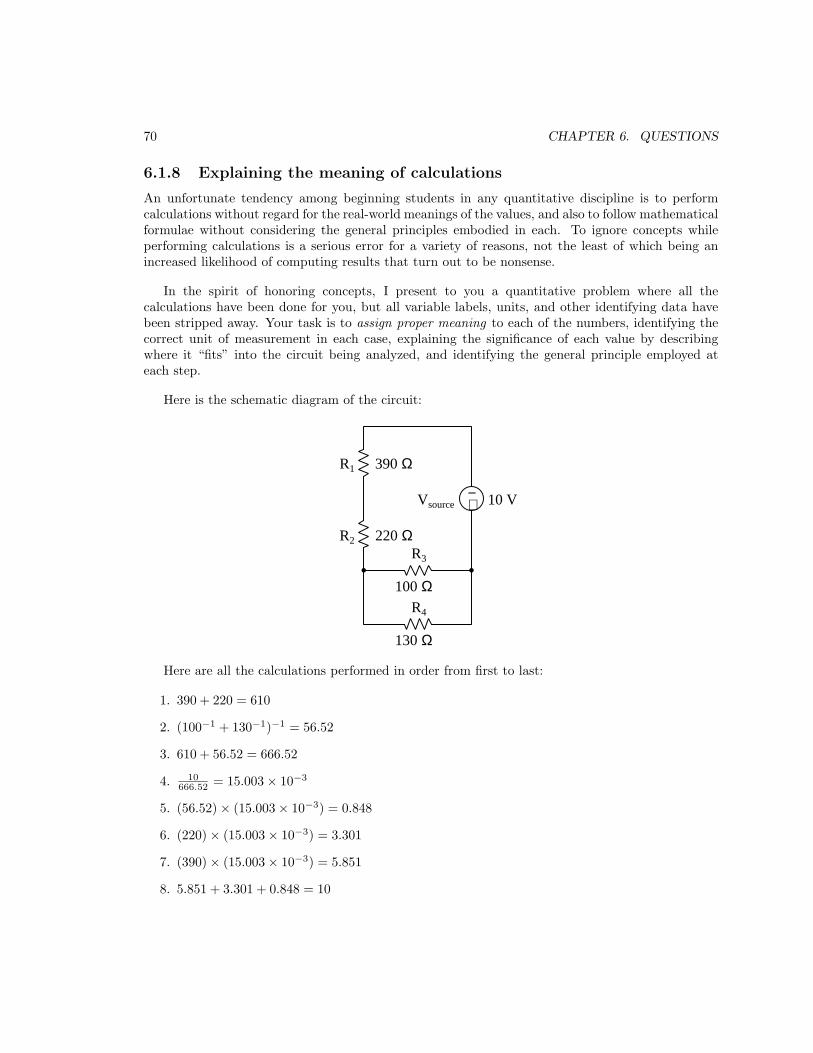
70 CHAPTER 6. QUESTIONS
6.1.8 Explaining the meaning of calculations
An unfortunate tendency among beginning students in any quantitative discipline is to performcalculations without regard for the real-world meanings of the values, and also to follow mathematicalformulae without considering the general principles embodied in each. To ignore concepts whileperforming calculations is a serious error for a variety of reasons, not the least of which being anincreased likelihood of computing results that turn out to be nonsense.
In the spirit of honoring concepts, I present to you a quantitative problem where all thecalculations have been done for you, but all variable labels, units, and other identifying data havebeen stripped away. Your task is to assign proper meaning to each of the numbers, identifying thecorrect unit of measurement in each case, explaining the significance of each value by describingwhere it “fits” into the circuit being analyzed, and identifying the general principle employed ateach step.
Here is the schematic diagram of the circuit:
+−
R1
R2
390 Ω
220 Ω
Vsource 10 V
R3
100 ΩR4
130 Ω
Here are all the calculations performed in order from first to last:
1. 390 + 220 = 610
2. (100−1 + 130−1)−1 = 56.52
3. 610 + 56.52 = 666.52
4. 10666.52 = 15.003 × 10⁻³
5. (56.52) × (15.003 × 10−3) = 0.848
6. (220) × (15.003 × 10−3) = 3.301
7. (390) × (15.003 × 10−3) = 5.851
8. 5.851 + 3.301 + 0.848 = 10

6.1. CONCEPTUAL REASONING 71
9. 0.848100 = 8.480 × 10⁻³
10. 0.848130 = 6.523 × 10⁻³
11. (8.480 × 10⁻³) + (6.523 × 10⁻³) = 15.003 × 10⁻³
12. 5.8512
390 = 87.79 × 10⁻³
13. 3.3012
220 = 49.52 × 10⁻³
14. 0.8482
100 = 7.191 × 10⁻³
15. 0.8482
130 = 5.532 × 10⁻³
16. 10 × (15.003 × 10−3) = 150.033 × 10⁻³
17. (87.79 × 10⁻³) + (49.52 × 10⁻³) + (7.191 × 10⁻³) + (5.532 × 10⁻³) = 150.033 × 10⁻³
Explain what each value means in the circuit, identify its unit of measurement, and identify thegeneral principle used to compute it!
Challenges
• Explain how you can check your own thinking as you solve quantitative problems, to avoid thedilemma of just “crunching numbers” to get an answer.
• For each calculated step shown, identify the physical Law or electric circuit principle beingapplied.
• Identify any of the calculations shown above whose order could be changed. In other words,can this problem be solved in a different order?
• Identify any of the calculations shown above that are not strictly necessary to the completeanalysis of the circuit, explaining why it has any merit at all.
• Do you see any alternative paths to a solution, involving specific calculations not shown above?

72 CHAPTER 6. QUESTIONS
6.1.9 Bridge networks
Which of these resistor network’s total resistance may be calculated using the analytical toolsexplained in this module’s full tutorial, and which network is impossible for us to analyze at thisstage of our learning?
5 Ω
13 Ω
9 Ω
4 Ω 3 Ω
Rtotal
5 Ω
13 Ω
9 Ω
4 Ω 3 Ω
Rtotal
For the network you can analyze, explain the steps you would take to compute its total resistance.For the network you cannot analyze, explain why it defies simplification.
Challenges
• Devise an experiment to empirically determine the total resistance of each resistor network.

6.2. QUANTITATIVE REASONING 73
6.2 Quantitative reasoning
These questions are designed to stimulate your computational thinking. In a Socratic discussion withyour instructor, the goal is for these questions to reveal your mathematical approach(es) to problem-solving so that good technique and sound reasoning may be reinforced. Your instructor may also poseadditional questions based on those assigned, in order to observe your problem-solving firsthand.
Mental arithmetic and estimations are strongly encouraged for all calculations, because withoutthese abilities you will be unable to readily detect errors caused by calculator misuse (e.g. keystrokeerrors).
You will note a conspicuous lack of answers given for these quantitative questions. Unlikestandard textbooks where answers to every other question are given somewhere toward the backof the book, here in these learning modules students must rely on other means to check their work.My advice is to use circuit simulation software such as SPICE to check the correctness of quantitativeanswers. Refer to those learning modules within this collection focusing on SPICE to see workedexamples which you may use directly as practice problems for your own study, and/or as templatesyou may modify to run your own analyses and generate your own practice problems.
Completely worked example problems found in the Tutorial may also serve as “test cases4” forgaining proficiency in the use of circuit simulation software, and then once that proficiency is gainedyou will never need to rely5 on an answer key!
4In other words, set up the circuit simulation software to analyze the same circuit examples found in the Tutorial.If the simulated results match the answers shown in the Tutorial, it confirms the simulation has properly run. Ifthe simulated results disagree with the Tutorial’s answers, something has been set up incorrectly in the simulationsoftware. Using every Tutorial as practice in this way will quickly develop proficiency in the use of circuit simulationsoftware.
5This approach is perfectly in keeping with the instructional philosophy of these learning modules: teaching students
to be self-sufficient thinkers. Answer keys can be useful, but it is even more useful to your long-term success to havea set of tools on hand for checking your own work, because once you have left school and are on your own, there willno longer be “answer keys” available for the problems you will have to solve.

74 CHAPTER 6. QUESTIONS
6.2.1 Miscellaneous physical constants
Note: constants shown in bold type are exact, not approximations. Parentheses show onestandard deviation (σ) of uncertainty in the final digits: for example, Avogadro’s number given as6.02214179(30) × 1023 means the center value (6.02214179× 10²³) plus or minus 0.00000030× 10²³.
Avogadro’s number (NA) = 6.02214179(30) × 1023 per mole (mol−1)
Boltzmann’s constant (k) = 1.3806504(24) × 10−23 Joules per Kelvin (J/K)
Electronic charge (e) = 1.602176487(40) × 10−19 Coulomb (C)
Faraday constant (F ) = 9.64853399(24) × 104 Coulombs per mole (C/mol)
Gravitational constant (G) = 6.67428(67) × 10−11 cubic meters per kilogram-seconds squared(m3/kg-s2)
Molar gas constant (R) = 8.314472(15) Joules per mole-Kelvin (J/mol-K) = 0.08205746(14) liters-atmospheres per mole-Kelvin
Planck constant (h) = 6.62606896(33) × 10−34 joule-seconds (J-s)
Stefan-Boltzmann constant (σ) = 5.670400(40) × 10−8 Watts per square meter-Kelvin4 (W/m2·K4)
Speed of light in a vacuum (c) = 299792458 meters per second (m/s) = 186282.4 miles persecond (mi/s)
Note: All constants taken from NIST data “Fundamental Physical Constants – Extensive Listing”,from http://physics.nist.gov/constants, National Institute of Standards and Technology(NIST), 2006.

6.2. QUANTITATIVE REASONING 75
6.2.2 Introduction to spreadsheets
A powerful computational tool you are encouraged to use in your work is a spreadsheet. Availableon most personal computers (e.g. Microsoft Excel), spreadsheet software performs numericalcalculations based on number values and formulae entered into cells of a grid. This grid istypically arranged as lettered columns and numbered rows, with each cell of the grid identifiedby its column/row coordinates (e.g. cell B3, cell A8). Each cell may contain a string of text, anumber value, or a mathematical formula. The spreadsheet automatically updates the results of allmathematical formulae whenever the entered number values are changed. This means it is possibleto set up a spreadsheet to perform a series of calculations on entered data, and those calculationswill be re-done by the computer any time the data points are edited in any way.
For example, the following spreadsheet calculates average speed based on entered values ofdistance traveled and time elapsed:
1
2
3
4
5
A B C
Distance traveled
Time elapsed
Kilometers
Hours
Average speed km/h
D
46.9
1.18
= B1 / B2
Text labels contained in cells A1 through A3 and cells C1 through C3 exist solely for readabilityand are not involved in any calculations. Cell B1 contains a sample distance value while cell B2contains a sample time value. The formula for computing speed is contained in cell B3. Note howthis formula begins with an “equals” symbol (=), references the values for distance and speed bylettered column and numbered row coordinates (B1 and B2), and uses a forward slash symbol fordivision (/). The coordinates B1 and B2 function as variables6 would in an algebraic formula.
When this spreadsheet is executed, the numerical value 39.74576 will appear in cell B3 ratherthan the formula = B1 / B2, because 39.74576 is the computed speed value given 46.9 kilometerstraveled over a period of 1.18 hours. If a different numerical value for distance is entered into cellB1 or a different value for time is entered into cell B2, cell B3’s value will automatically update. Allyou need to do is set up the given values and any formulae into the spreadsheet, and the computerwill do all the calculations for you.
Cell B3 may be referenced by other formulae in the spreadsheet if desired, since it is a variablejust like the given values contained in B1 and B2. This means it is possible to set up an entire chainof calculations, one dependent on the result of another, in order to arrive at a final value. Thearrangement of the given data and formulae need not follow any pattern on the grid, which meansyou may place them anywhere.
6Spreadsheets may also provide means to attach text labels to cells for use as variable names (Microsoft Excelsimply calls these labels “names”), but for simple spreadsheets such as those shown here it’s usually easier just to usethe standard coordinate naming for each cell.

76 CHAPTER 6. QUESTIONS
Common7 arithmetic operations available for your use in a spreadsheet include the following:
• Addition (+)
• Subtraction (-)
• Multiplication (*)
• Division (/)
• Powers (^)
• Square roots (sqrt())
• Logarithms (ln() , log10())
Parentheses may be used to ensure8 proper order of operations within a complex formula.Consider this example of a spreadsheet implementing the quadratic formula, used to solve for rootsof a polynomial expression in the form of ax2 + bx + c:
x =−b ±
√b2 − 4ac
2a
1
2
3
4
5
A B
5
-2
x_1
x_2
a =
b =
c =
9
= (-B4 - sqrt((B4^2) - (4*B3*B5))) / (2*B3)
= (-B4 + sqrt((B4^2) - (4*B3*B5))) / (2*B3)
This example is configured to compute roots9 of the polynomial 9x2 + 5x− 2 because the valuesof 9, 5, and −2 have been inserted into cells B3, B4, and B5, respectively. Once this spreadsheet hasbeen built, though, it may be used to calculate the roots of any second-degree polynomial expressionsimply by entering the new a, b, and c coefficients into cells B3 through B5. The numerical valuesappearing in cells B1 and B2 will be automatically updated by the computer immediately followingany changes made to the coefficients.
7Modern spreadsheet software offers a bewildering array of mathematical functions you may use in yourcomputations. I recommend you consult the documentation for your particular spreadsheet for information onoperations other than those listed here.
8Spreadsheet programs, like text-based programming languages, are designed to follow standard order of operationsby default. However, my personal preference is to use parentheses even where strictly unnecessary just to make itclear to any other person viewing the formula what the intended order of operations is.
9Reviewing some algebra here, a root is a value for x that yields an overall value of zero for the polynomial. Forthis polynomial (9x
2 +5x−2) the two roots happen to be x = 0.269381 and x = −0.82494, with these values displayedin cells B1 and B2, respectively upon execution of the spreadsheet.

6.2. QUANTITATIVE REASONING 77
Alternatively, one could break up the long quadratic formula into smaller pieces like this:
y =√
b2 − 4ac z = 2a
x =−b ± y
z
1
2
3
4
5
A B
5
-2
x_1
x_2
a =
b =
c =
9
C
= sqrt((B4^2) - (4*B3*B5))
= 2*B3
= (-B4 + C1) / C2
= (-B4 - C1) / C2
Note how the square-root term (y) is calculated in cell C1, and the denominator term (z) in cellC2. This makes the two final formulae (in cells B1 and B2) simpler to interpret. The positioning ofall these cells on the grid is completely arbitrary10 – all that matters is that they properly referenceeach other in the formulae.
Spreadsheets are particularly useful for situations where the same set of calculations representinga circuit or other system must be repeated for different initial conditions. The power of a spreadsheetis that it automates what would otherwise be a tedious set of calculations. One specific applicationof this is to simulate the effects of various components within a circuit failing with abnormal values(e.g. a shorted resistor simulated by making its value nearly zero; an open resistor simulated bymaking its value extremely large). Another application is analyzing the behavior of a circuit designgiven new components that are out of specification, and/or aging components experiencing driftover time.
10My personal preference is to locate all the “given” data in the upper-left cells of the spreadsheet grid (each datapoint flanked by a sensible name in the cell to the left and units of measurement in the cell to the right as illustratedin the first distance/time spreadsheet example), sometimes coloring them in order to clearly distinguish which cellscontain entered data versus which cells contain computed results from formulae. I like to place all formulae in cellsbelow the given data, and try to arrange them in logical order so that anyone examining my spreadsheet will be ableto figure out how I constructed a solution. This is a general principle I believe all computer programmers shouldfollow: document and arrange your code to make it easy for other people to learn from it.

78 CHAPTER 6. QUESTIONS
6.2.3 Problem-solving example: mixed-source circuit
An excellent type of quantitative problem for students learning to apply Ohm’s Law, Joule’s Law,Kirchhoff’s Laws, and the properties of series and parallel networks is where voltage and currentsources coexist within the same circuit, in such a way that all currents are easily defined by thosesources. This type of analytical problem forces the problem-solver to carefully consider thosefundamental Laws to see where each one fits.
Take for example the following circuit, containing two constant-current elements11 and twoconstant-voltage elements. Our task is to calculate all voltages and currents not specified by thecomponent ratings, as well as to determine directions of current, polarities of voltage, and theidentity of each component as being either an electrical source or an electrical load:
+ −
+ −
4 A
3 A
12 V
9 V5 Ω
2 Ω
3 Ω
11I hesitate to use the term “source” to describe each, since we often discover one or more of them behaving asloads!
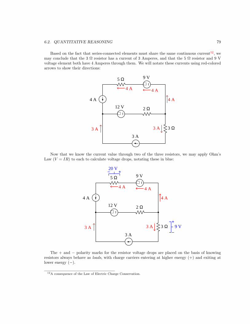
6.2. QUANTITATIVE REASONING 79
Based on the fact that series-connected elements must share the same continuous current12, wemay conclude that the 3 Ω resistor has a current of 3 Amperes, and that the 5 Ω resistor and 9 Vvoltage element both have 4 Amperes through them. We will notate these currents using red-coloredarrows to show their directions:
+ −
+ −
4 A
3 A
12 V
9 V5 Ω
2 Ω
3 Ω
4 A 4 A
4 A
3 A3 A
Now that we know the current value through two of the three resistors, we may apply Ohm’sLaw (V = IR) to each to calculate voltage drops, notating these in blue:
+ −
+ −
4 A
3 A
12 V
9 V5 Ω
2 Ω
3 Ω
4 A 4 A
4 A
3 A3 A
20 V
9 V
The + and − polarity marks for the resistor voltage drops are placed on the basis of knowingresistors always behave as loads, with charge carriers entering at higher energy (+) and exiting atlower energy (−).
12A consequence of the Law of Electric Charge Conservation.

80 CHAPTER 6. QUESTIONS
Next, we see an application of Kirchhoff’s Current Law13 at the left-hand node, where the 3Ampere and 4 Ampere currents merge. This results in 7 Amperes of current from left to rightthrough the 12 Volt element and the 2 Ω resistor. Applying Ohm’s Law again to that resistor(V = IR), we calculate its voltage drop to be 14 Volts:
+ −
+ −
4 A
3 A
12 V
9 V5 Ω
2 Ω
3 Ω
4 A 4 A
4 A
3 A3 A
20 V
9 V
7 A 7 A
14 V
We do not yet know the voltage across each constant-current element, but we may determinethis by using Kirchhoff’s Voltage Law14. Stepping around each of the two “loops” in this circuit andsumming all the known voltages to determine the unknown voltage necessary to bring that sum tozero:
Lower loop, stepping clockwise starting from lower-left corner:
0 V − 12 V − 14 V − 9 V + V3A = 0
V3A = 35 V
Upper loop, stepping counter-clockwise starting from lower-left corner:
−12 V − 14 V + 0 V + 9 V − 20 V + V4A = 0
V4A = 37 V
13Another consequence of the Law of Electric Charge Conservation.14A consequence of the Law of Energy Conservation, that electric charge carriers flowing around a circuit must gain
exactly as much energy as they lose.
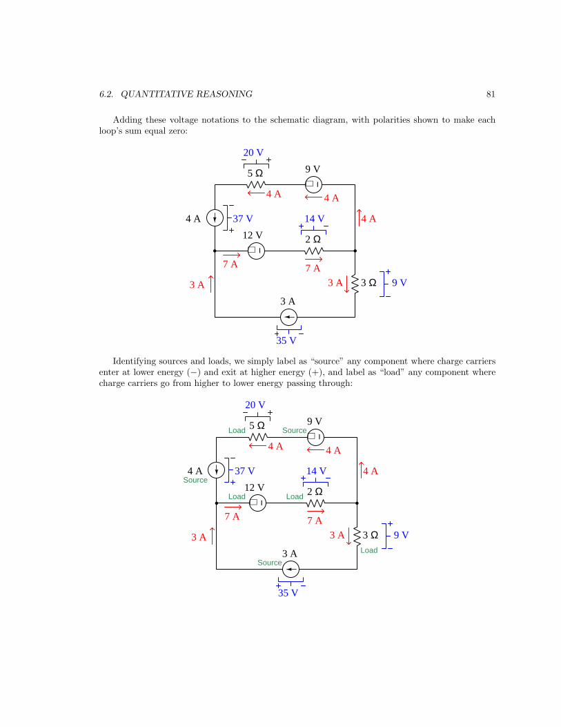
6.2. QUANTITATIVE REASONING 81
Adding these voltage notations to the schematic diagram, with polarities shown to make eachloop’s sum equal zero:
+ −
+ −
4 A
3 A
12 V
9 V5 Ω
2 Ω
3 Ω
4 A 4 A
4 A
3 A3 A
20 V
9 V
7 A 7 A
14 V
35 V
37 V
Identifying sources and loads, we simply label as “source” any component where charge carriersenter at lower energy (−) and exit at higher energy (+), and label as “load” any component wherecharge carriers go from higher to lower energy passing through:
+ −
+ −
4 A
3 A
12 V
9 V5 Ω
2 Ω
3 Ω
4 A 4 A
4 A
3 A3 A
20 V
9 V
7 A 7 A
14 V
35 V
37 VSource
Load
Source
Source
LoadLoad
Load

82 CHAPTER 6. QUESTIONS
Lastly, we may calculate power for each component using Joule’s Law (P = IV ):
+ −
+ −
4 A
3 A
12 V
9 V5 Ω
2 Ω
3 Ω
4 A 4 A
4 A
3 A3 A
20 V
9 V
7 A 7 A
14 V
35 V
37 VSource
Load
Source
Source
LoadLoad
Load
80 W36 W
148 W
84 W
98 W
27 W105 W
A good check of our work is to verify that the sum of all source powers equals the sum of all loadpowers:
148 W + 105 W + 36 W = 80 W + 84 W + 98 W + 27 W
289 W = 289 W
Although one may argue that circuits such as this are unrealistic, they provide an excellentpractice opportunity to apply all the fundamental laws and properties of circuits: Ohm’s Law,Joule’s Law, Kirchhoff’s Laws, and series/parallel network properties. The basic problem-solvingstrategy, regardless of circuit shape, is to see where any of these laws or properties apply and thenannotate the results of that application, repeating the process until all parameters are solved.
It is worth noting that when students struggle with circuit analysis and/or circuit fault diagnosis,the root cause is more often than not a failure to master these foundational principles. If yourcomprehension of any of these laws or principles is weak, you will invariably struggle later on, sotake the time to absolutely master these!

6.2. QUANTITATIVE REASONING 83
6.2.4 Building a custom resistance value
Suppose you have a large assortment of fixed-value resistors, with the following resistance valuesavailable: 100 Ω, 220 Ω, 270 Ω, 330 Ω, 390 Ω, 470 Ω, 510 Ω, 830 Ω, 1 kΩ. However, what youactually need for a particular project is a 350 Ω resistance.
Describe how you could connect some of the resistors together from your assortment to create asingle resistance of 350 Ω.
Challenges
• If each of these resistors is rated at 14 Watt power dissipation, determine the maximum amount
of power your proposed network will be able to dissipate without damage.
• Assuming individual resistor tolerances of ± 5%, calculate the highest and lowest possibleresistance values for your network.

84 CHAPTER 6. QUESTIONS
6.2.5 Two different LED circuits
Suppose we wish to power three light-emitting diodes (LEDs), each one rated at 1.6 Volts and 20milliAmperes, with a single 6 Volt battery. We have two different ways of doing this, one wayconnecting the three LEDs in series and the other connecting the three LEDs in parallel with eachother:
6 V
R1
6 V
R2
Calculate the necessary resistor value for each of these circuits to limit each LED’s current to 20mA:
R1 =
R2 =
Which of these two circuits will be the most energy-efficient, making the best use of the battery’senergy to produce light, and wasting the least amount of energy in the form of heat?
Challenges
• Calculate the power dissipated by each resistor.
• Suppose one of the LEDs fails open in each of the circuits. Predict the effect of this fault ineach of the circuit configurations.
• Suppose one of the LEDs fails shorted in each of the circuits. Predict the effect of this faultin each of the circuit configurations.

6.2. QUANTITATIVE REASONING 85
6.2.6 Four-resistor circuit
Calculate all voltages and currents in this circuit, given only the resistor values and the source value:
1 kΩ R1R2
R3
R4
11 V
500 Ω
150 Ω
450 Ω
R1 R2 R3 R4 Source
V
I
Challenges
• Apply Kirchhoff’s Voltage Law to the R1-R2-Source loop of the circuit, proving the sum ofthose voltages equals zero.
• Apply Kirchhoff’s Voltage Law to the R3-R4-Source-R2 loop of the circuit, proving the sumof those voltages equals zero.
• Apply Kirchhoff’s Current Law to the node below the source, proving the sum of currentsentering and exiting the node equals zero.

86 CHAPTER 6. QUESTIONS
6.2.7 Five-resistor circuit
Calculate all voltages and currents in this circuit, given only the resistor values and the source value:
R2
R3
R1 R4
R5
32 V
1 kΩ
2.2 kΩ790 Ω
8.6 kΩ
630 Ω
R1 R2 R3 R4 R5 Source
V
I
Challenges
• Apply Kirchhoff’s Voltage Law to the R1-R2-Source loop of the circuit, proving the sum ofthose voltages equals zero.
• Apply Kirchhoff’s Voltage Law to the R2-R3-Source loop of the circuit, proving the sum ofthose voltages equals zero.
• Apply Kirchhoff’s Current Law to the node lower-left, proving the sum of currents enteringand exiting the node equals zero.
• Explain what would happen if the diagonal wire were severed.

6.2. QUANTITATIVE REASONING 87
6.2.8 Terminal-block resistor circuit
Terminal blocks are mechanical assemblies using screws or spring-clips to secure connections to metalwires and component leads, commonly used in industrial circuit to organize wire connections andfacilitate quick alterations of circuit connections. The following photograph shows a typical terminalblock installation in an industrial wiring panel:
Note how each of the terminal blocks is uniquely numbered, and how many of the wires enteringthe left-hand side of each block bears a label identifying which terminal it should be connected to(e.g. “TB1-4” means terminal number 4 of terminal block assembly TB1). Another photographshows a different style of terminal block, using spring clips rather than screws to clamp wire-endsto the metal bar inside of each terminal block:

88 CHAPTER 6. QUESTIONS
In this next image, we see five resistors attached to ten terminal blocks, the left-hand side ofeach terminal block ready to receive “jumper” wires to connect these resistors to each other to forma network:
R1
R2
R3
R4
R5
1
2
3
4
5
6
7
8
9
0
Terminalblocks
+-
6 V
Write a list of necessary “jumper” wire connections to make between these numbered terminalblocks in order to create the following series-parallel circuit, then calculate all resistor voltage dropsassuming each resistor is 1000 Ω in value:
R1
R2
R3
R4
R56 V
Next, apply Kirchhoff’s Voltage Law to the voltages within the loop represented by the terminalsequence 0-2-5-4-0. In other words, tally the voltage gains and losses as an imaginary “test charge”is moved from terminal 0 to terminal 2 to terminal 5 to terminal 4 to terminal 0 in this resistornetwork.
Lastly, determine V7−1 following the convention that the voltmeter’s red test lead contacts thefirst subscripted test point and the black test lead contacts the second.

6.2. QUANTITATIVE REASONING 89
Challenges
• A useful problem-solving technique when designing circuits to be constructed on a terminalblock is to label the components in a schematic diagram with terminal numbers. Do thatfor this problem, and show how this step simplifies the process of identifying where to placeconnecting “jumper” wires.
• Identify a single resistor fault that will make VR1 = 0 Volts.
• Identify a single resistor fault that will make VR3 = 6 Volts.

90 CHAPTER 6. QUESTIONS
6.2.9 Mixed-source circuits
The following circuits contain a combination of constant-voltage and constant-current components.Constant-voltage components, of course, maintain the same voltage for all current conditions whileconstant-current components maintain the same current for all voltage conditions. While theseconstant-parameter components are commonly referred to as sources, it should be realized that theymay in fact behave as loads if overpowered by another source.
Based on this knowledge, as well as Ohm’s Law, Kirchhoff’s Laws, and other foundationalprinciples of electric circuits, determine all component voltages and component currents in thefollowing circuits, being sure to specify the polarity (+, −) of each voltage and the direction(conventional flow notation) of each current. Also, explain how you used your knowledge offundamental circuit principles to determine each of these parameters:
Circuit #1
I1+−V1 R1
R2
2 Ω
4 Ω
6 V 5 A
• IV 1 =
• VR1 =
• IR1 =
• VR2 =
• IR2 =
• VI1 =
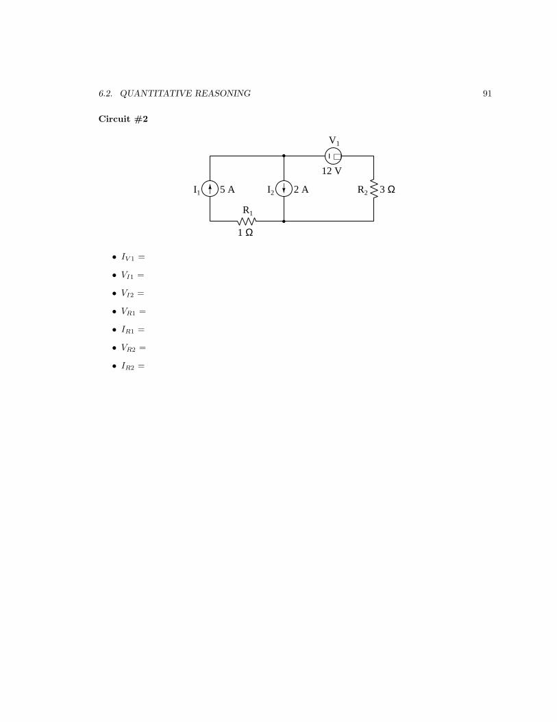
6.2. QUANTITATIVE REASONING 91
Circuit #2
+−
R1
R2I1 I2
V1
5 A 2 A
12 V
3 Ω
1 Ω
• IV 1 =
• VI1 =
• VI2 =
• VR1 =
• IR1 =
• VR2 =
• IR2 =

92 CHAPTER 6. QUESTIONS
Circuit #3
+ −
R1
R2I1 I2
V1
2 A 3 Ω
10 V
2 Ω
3 A
• IV 1 =
• VI1 =
• VI2 =
• VR1 =
• IR1 =
• VR2 =
• IR2 =

6.2. QUANTITATIVE REASONING 93
Circuit #4
+−
R1
R2I1
I2V1
2 Ω
6 A
+−
5 A
2 Ω
+−8 V
V2 3 V V3 6 V
• IV 1 =
• IV 2 =
• IV 3 =
• VI1 =
• VI2 =
• VR1 =
• VR2 =
• IR1 =
• IR2 =
Challenges
• What would happen if two voltage sources of differing voltage ratings were connected directlyin parallel with each other, with matching polarities?
• What would happen if two current sources of differing current ratings were connected directlyin series with each other, with matching current directions?

94 CHAPTER 6. QUESTIONS
6.2.10 More mixed-source circuits
The following circuits contain a combination of constant-voltage and constant-current components.Constant-voltage components, of course, maintain the same voltage for all current conditions whileconstant-current components maintain the same current for all voltage conditions. While theseconstant-parameter components are commonly referred to as sources, it should be realized that theymay in fact behave as loads if overpowered by another source.
Based on this knowledge, as well as Ohm’s Law, Kirchhoff’s Laws, and other foundationalprinciples of electric circuits, determine all component voltages and component currents in thefollowing circuits, being sure to specify the polarity (+, −) of each voltage and the direction(conventional flow notation) of each current. Use this information to determine whether eachcomponent functions as a source or as a load. Also, explain how you used your knowledge offundamental circuit principles to to determine each of these parameters:
Circuit #1
+−
+ −6 V
10 V
3 A
1 A
2 A
2 Ω
5 Ω
7 Ω
• Current through 10 V component =
• Current through 6 V component =
• Voltage across 3 A component =
• Voltage across 2 A component =
• Voltage across 1 A component =
• Current through 7 Ω resistor =
• Current through 5 Ω resistor =
• Current through 2 Ω resistor =
• Voltage across 7 Ω resistor =

6.2. QUANTITATIVE REASONING 95
• Voltage across 5 Ω resistor =
• Voltage across 2 Ω resistor =

96 CHAPTER 6. QUESTIONS
Circuit #2
+−
+−
+−
+−
7 Ω 5 V
3 Ω
5 Ω3 A8 V 1 Ω 10 V
4 A
2 A
2 V
• Current through 10 V component =
• Current through 8 V component =
• Current through 5 V component =
• Current through 2 V component =
• Voltage across 4 A component =
• Voltage across 3 A component =
• Voltage across 2 A component =
• Current through 7 Ω resistor =
• Current through 5 Ω resistor =
• Current through 3 Ω resistor =
• Current through 1 Ω resistor =
• Voltage across 7 Ω resistor =
• Voltage across 5 Ω resistor =
• Voltage across 3 Ω resistor =
• Voltage across 1 Ω resistor =
Challenges
• What does it mean for a constant-voltage or constant-current component to behave as a source?

6.2. QUANTITATIVE REASONING 97
• What does it mean for a constant-voltage or constant-current component to behave as a load?
• Modify any single component value and determine the effect(s) of that change on all voltages,currents, and source/load determinations.
6.2.11 Circuit with unknown source value
Calculate all voltages and currents in this circuit, given only the resistor values and one of thecurrent values:
R1
R2
R3 R4
R5V1
16 mA
2.2 kΩ 1.2 kΩ
4.7 kΩ
1 kΩ 330 Ω
R1 R2 R3 R4 R5 Source
V
I
Challenges
• Identify the effect on IR2 if resistor R3 happens to fail open.
• Identify the effect on VR1 if resistor R4 happens to fail shorted.
• Identify the effect on VR1 if resistor R5 happens to fail open.
• Identify the effect on VR4 if resistor R5 happens to fail shorted.
• Demonstrate how to apply Kirchhoff’s Voltage Law in this circuit, once you have obtainedvalues for all voltages and currents.
• Demonstrate how to apply Kirchhoff’s Current Law in this circuit, once you have obtainedvalues for all voltages and currents.

98 CHAPTER 6. QUESTIONS
6.2.12 Incorrect voltmeter readings
Suppose you constructed a simple two-resistor voltage divider using identical 1 MΩ resistors, poweredby a source voltage of exactly 15 Volts. Measuring voltage across each resistor using a digitalmultimeter (DMM), one at a time, you obtain equal measurements of 7.200 Volts.
This, of course, is less than the perfect 7.500 Volts one would expect across each resistor of sucha simple voltage divider. Explain why the voltmeter gives less-than-perfect measurements of resistorvoltage, and calculate the voltmeter’s internal resistance based on this measurement.
Challenges
• How can we tell that the 7.200 Volt reading was not due to imperfections in the resistors?

6.2. QUANTITATIVE REASONING 99
6.2.13 Interpreting a SPICE analysis
A computer program called SPICE was developed in the early 1970’s, whereby a text-baseddescription of an electric circuit (called a netlist) could be entered into a computer, and thencomputer would be directed to apply fundamental laws of electric circuits to the netlist circuitdescription according to algorithms coded in SPICE.
A netlist specifying the circuit to SPICE is shown here, followed by a schematic diagram (forillustrative purposes only, not for the computer running SPICE) showing all the numbered “nodes”which SPICE uses to define connection points between components:
* Five-resistor series-parallel DC circuit
v1 1 0 dc 7
r1 1 2 4700
r2 2 3 3300
r3 3 5 2700
r4 3 4 2200
r5 4 6 1000
vamm1 5 0
vamm2 6 0
.dc v1 7 7 1
.print dc v(1,2) v(2,3) v(3,4)
.print dc v(3,5) v(4,6) i(v1)
.print dc i(vamm1) i(vamm2)
.end
+−v1
1 2
3
0
r1
r2
r3
4.7 kΩ
3.3 kΩ
2.2 kΩ
4
7 V
r4r5
1 kΩ
2.7 kΩ0
+−+−
vamm1
vamm2
0 V
0 V
5
6
Note: this schematic diagram isshown only for your benefit. Thecomputer running SPICE softwareneeds only a text "netlist" to describe the circuit, not a graphicalimage!
Note the inclusion of zero-voltage sources vamm1 and vamm2, used in this netlist as ammeters forthe purpose of measuring current through R3 and R4 ↔ R5, respectively. Legacy versions of SPICE

100 CHAPTER 6. QUESTIONS
could only analyze currents through voltage sources, and so if one needed an ammeter placed ina SPICE circuit, the solution was to insert a zero-voltage source to prompt SPICE to report theamount of current through it.
Identify how each component’s connecting nodes and essential parameters (i.e. values) arespecified in the netlist. Based on the what you can identify in this netlist, perform your owncalculations using Ohm’s Law to predict all other values in this circuit.
When SPICE (software version 2G6) processes the contents of this “netlist” file, it outputs atext description of the analysis. The following text has been edited for clarity (e.g. blank lines,extraneous characters, and statistical data removed):
v1 v(1,2) v(2,3) v(3,4)
7.000E+00 3.476E+00 2.441E+00 7.446E-01
v1 v(3,5) v(4,6) i(v1)
7.000E+00 1.083E+00 3.385E-01 -7.396E-04
v1 i(vamm1) i(vamm2)
7.000E+00 4.011E-04 3.385E-04
The same netlist processed by a more modern version of SPICE (NGSPICE version 26) producesthe following analysis:
--------------------------------------------------------------------
Index v-sweep v(1)-v(2) v(2)-v(3) v(3)-v(4)
--------------------------------------------------------------------
0 7.000000e+00 3.476182e+00 2.440723e+00 7.446275e-01
--------------------------------------------------------------------
Index v-sweep v(3)-v(5) v(4)-v(6) v1#branch
--------------------------------------------------------------------
0 7.000000e+00 1.083095e+00 3.384670e-01 -7.39613e-04
--------------------------------------------------------------------
Index v-sweep vamm1#branch vamm2#branch
--------------------------------------------------------------------
0 7.000000e+00 4.011461e-04 3.384670e-04
Interpret the output of SPICE to the best of your ability. Identify all parameters that you can,and see if the results of the computer’s analysis agree with your own calculations.
Once you become familiar with the analysis data format of SPICE, you will be able to usethe “Gallery” of SPICE simulations found in the “SPICE Modeling of Resistor Circuits” moduleas practice problems for developing your own circuit analysis skills. If you become proficient withcreating your own netlists and running SPICE simulations, your freedom to create practice problemscomplete with answers will be unlimited!

6.2. QUANTITATIVE REASONING 101
Challenges
• SPICE utilizes power-of-ten notation for small and large values. The standard representationof this in a plain-text format is a capital letter E followed by the power value. Identify anysuch figures in the SPICE output listing, and express them in regular decimal notation.
• Modify this SPICE netlist to utilize a voltage source with a value of 16 Volts instead of 7 Volts.
• Modify this SPICE netlist to specify resistor R1’s resistance using scientific (power-of-ten)notation.
• Modify this SPICE netlist to specify resistor R1’s resistance using metric prefix (“kilo”)notation.
• Explain why i(v1) registers as a negative value while both i(vamm1) and i(vamm2) registeras positive values.
• Apply Kirchhoff’s Current Law to current values in this circuit.

102 CHAPTER 6. QUESTIONS
6.3 Diagnostic reasoning
These questions are designed to stimulate your deductive and inductive thinking, where you mustapply general principles to specific scenarios (deductive) and also derive conclusions about the failedcircuit from specific details (inductive). In a Socratic discussion with your instructor, the goal is forthese questions to reinforce your recall and use of general circuit principles and also challenge yourability to integrate multiple symptoms into a sensible explanation of what’s wrong in a circuit. Yourinstructor may also pose additional questions based on those assigned, in order to further challengeand sharpen your diagnostic abilities.
As always, your goal is to fully explain your analysis of each problem. Simply obtaining acorrect answer is not good enough – you must also demonstrate sound reasoning in order tosuccessfully complete the assignment. Your instructor’s responsibility is to probe and challengeyour understanding of the relevant principles and analytical processes in order to ensure you have astrong foundation upon which to build further understanding.
You will note a conspicuous lack of answers given for these diagnostic questions. Unlike standardtextbooks where answers to every other question are given somewhere toward the back of the book,here in these learning modules students must rely on other means to check their work. The best wayby far is to debate the answers with fellow students and also with the instructor during the Socraticdialogue sessions intended to be used with these learning modules. Reasoning through challengingquestions with other people is an excellent tool for developing strong reasoning skills.
Another means of checking your diagnostic answers, where applicable, is to use circuit simulationsoftware to explore the effects of faults placed in circuits. For example, if one of these diagnosticquestions requires that you predict the effect of an open or a short in a circuit, you may check thevalidity of your work by simulating that same fault (substituting a very high resistance in place ofthat component for an open, and substituting a very low resistance for a short) within software andseeing if the results agree.

6.3. DIAGNOSTIC REASONING 103
6.3.1 Fault in a solderless breadboard circuit
A student built this resistor circuit on a solderless breadboard, but made a mistake positioningresistor R3. It should be located one hole to the left instead of where it is right now:
+-
R5
R1R
2
R3
R4
Determine the amount of voltage dropped across each resistor in this faulty circuit configuration,assuming the battery outputs 9 Volts:
• R1 = 2 kΩ VR1 =
• R2 = 1 kΩ VR2 =
• R3 = 3.3 kΩ VR3 =
• R4 = 4.7 kΩ VR4 =
• R5 = 4.7 kΩ VR5 =
Suppose the student realizes there is a mistake, and in an attempt to correct the mistake decidesto move the battery’s positive (+) wire one hole to the right on the breadboard in order to alignwith resistor R3. If this is the only change made to the circuit, what will be the result?
Challenges
• Identify how the student could have determined a problem existed in the circuit prior toconnecting a battery to power it.

104 CHAPTER 6. QUESTIONS
6.3.2 Faults in a printed circuit
Predict the effects of the following faults in this circuit, one fault at a time, assuming the powersupply is a fixed-voltage unit:
Printed circuit board withsurface-mount resistors
R1
R2
R3
R4
+ -
Powersupply
• If R1 fails open . . .
• If R2 fails open . . .
• If R3 fails open . . .
• If R4 fails open . . .
• If R1 fails shorted . . .
• If R2 fails shorted . . .
• If R3 fails shorted . . .
• If R4 fails shorted . . .
Challenges
• Components soldered to circuit boards cannot be easily removed, as de-soldering is required.This makes it difficult to test for current through any component, as there is no convenientway to break the circuit so as to insert an ammeter. Describe how it may be possible to infercurrent through certain circuit board components using only a voltmeter.

6.3. DIAGNOSTIC REASONING 105
6.3.3 Faulty electric lamp array
Something has failed in this array of electric lamps, because only the middle and bottom strings areilluminating. None of the lamps in the upper string emit any light. A technician takes a voltagemeasurement (as shown):
OFF
COMA
V A
V A
36 V
Identify at least two individual faults, either one independently capable of accounting for thesymptoms of this circuit.
Challenges
• Suppose the voltmeter registered 36 Volts instead of 0 Volts in this failed circuit. Identify atleast two independent faults which could explain all symptoms.
• Suppose nothing was failed in this circuit. How much voltage should the voltmeter registerwhen connected as shown?
• Suppose nothing was failed in this circuit. What would happen if the DMM were connectedto the circuit in the same place, but configured to be an ammeter rather than a voltmeter?

106 CHAPTER 6. QUESTIONS

Chapter 7
Projects and Experiments
The following project and experiment descriptions outline things you can build to help youunderstand circuits. With any real-world project or experiment there exists the potential for physicalharm. Electricity can be very dangerous in certain circumstances, and you should follow proper safety
precautions at all times!
7.1 Recommended practices
This section outlines some recommended practices for all circuits you design and construct.
107
108 CHAPTER 7. PROJECTS AND EXPERIMENTS
7.1.1 Safety first!
Electricity, when passed through the human body, causes uncomfortable sensations and in largeenough measures1 will cause muscles to involuntarily contract. The overriding of your nervoussystem by the passage of electrical current through your body is particularly dangerous in regardto your heart, which is a vital muscle. Very large amounts of current can produce serious internalburns in addition to all the other effects.
Cardio-pulmonary resuscitation (CPR) is the standard first-aid for any victim of electrical shock.This is a very good skill to acquire if you intend to work with others on dangerous electrical circuits.You should never perform tests or work on such circuits unless someone else is present who isproficient in CPR.
As a general rule, any voltage in excess of 30 Volts poses a definitive electric shock hazard, becausebeyond this level human skin does not have enough resistance to safely limit current through thebody. “Live” work of any kind with circuits over 30 volts should be avoided, and if unavoidableshould only be done using electrically insulated tools and other protective equipment (e.g. insulatingshoes and gloves). If you are unsure of the hazards, or feel unsafe at any time, stop all work anddistance yourself from the circuit!
A policy I strongly recommend for students learning about electricity is to never come into
electrical contact2 with an energized conductor, no matter what the circuit’s voltage3 level! Enforcingthis policy may seem ridiculous when the circuit in question is powered by a single battery smallerthan the palm of your hand, but it is precisely this instilled habit which will save a person frombodily harm when working with more dangerous circuits. Experience has taught me that studentswho learn early on to be careless with safe circuits have a tendency to be careless later with dangerouscircuits!
In addition to the electrical hazards of shock and burns, the construction of projects and runningof experiments often poses other hazards such as working with hand and power tools, potential
1Professor Charles Dalziel published a research paper in 1961 called “The Deleterious Effects of Electric Shock”detailing the results of electric shock experiments with both human and animal subjects. The threshold of perceptionfor human subjects holding a conductor in their hand was in the range of 1 milliampere of current (less than thisfor alternating current, and generally less for female subjects than for male). Loss of muscular control was exhibitedby half of Dalziel’s subjects at less than 10 milliamperes alternating current. Extreme pain, difficulty breathing,and loss of all muscular control occurred for over 99% of his subjects at direct currents less than 100 milliamperesand alternating currents less than 30 milliamperes. In summary, it doesn’t require much electric current to inducepainful and even life-threatening effects in the human body! Your first and best protection against electric shock ismaintaining an insulating barrier between your body and the circuit in question, such that current from that circuitwill be unable to flow through your body.
2By “electrical contact” I mean either directly touching an energized conductor with any part of your body, orindirectly touching it through a conductive tool. The only physical contact you should ever make with an energizedconductor is via an electrically insulated tool, for example a screwdriver with an electrically insulated handle, or aninsulated test probe for some instrument.
3Another reason for consistently enforcing this policy, even on low-voltage circuits, is due to the dangers that evensome low-voltage circuits harbor. A single 12 Volt automobile battery, for example, can cause a surprising amount ofdamage if short-circuited simply due to the high current levels (i.e. very low internal resistance) it is capable of, eventhough the voltage level is too low to cause a shock through the skin. Mechanics wearing metal rings, for example,are at risk from severe burns if their rings happen to short-circuit such a battery! Furthermore, even when working oncircuits that are simply too low-power (low voltage and low current) to cause any bodily harm, touching them whileenergized can pose a threat to the circuit components themselves. In summary, it generally wise (and always a goodhabit to build) to “power down” any circuit before making contact between it and your body.

7.1. RECOMMENDED PRACTICES 109
contact with high temperatures, potential chemical exposure, etc. You should never proceed with aproject or experiment if you are unaware of proper tool use or lack basic protective measures (e.g.personal protective equipment such as safety glasses) against such hazards.
Some other safety-related practices should be followed as well:
• All power conductors extending outward from the project must be firmly strain-relieved (e.g.“cord grips” used on line power cords), so that an accidental tug or drop will not compromisecircuit integrity.
• All electrical connections must be sound and appropriately made (e.g. soldered wire jointsrather than twisted-and-taped; terminal blocks rather than solderless breadboards for high-current or high-voltage circuits). Use “touch-safe” terminal connections with recessed metalparts to minimize risk of accidental contact.
• Always provide overcurrent protection in any circuit you build. Always. This may be in theform of a fuse, a circuit breaker, and/or an electronically current-limited power supply.
• Always ensure circuit conductors are rated for more current than the overcurrent protectionlimit. Always. A fuse does no good if the wire or printed circuit board trace will “blow” beforeit does!
• Always bond metal enclosures to Earth ground for any line-powered circuit. Always. Ensuringan equipotential state between the enclosure and Earth by making the enclosure electricallycommon with Earth ground ensures no electric shock can occur simply by one’s body bridgingbetween the Earth and the enclosure.
• Avoid building a high-energy circuit when a low-energy circuit will suffice. For example,I always recommend beginning students power their first DC resistor circuits using smallbatteries rather than with line-powered DC power supplies. The intrinsic energy limitationsof a dry-cell battery make accidents highly unlikely.
• Use line power receptacles that are GFCI (Ground Fault Current Interrupting) to help avoidelectric shock from making accidental contact with a “hot” line conductor.
• Always wear eye protection when working with tools or live systems having the potential toeject material into the air. Examples of such activities include soldering, drilling, grinding,cutting, wire stripping, working on or near energized circuits, etc.
• Always use a step-stool or stepladder to reach high places. Never stand on something notdesigned to support a human load.
• When in doubt, ask an expert. If anything even seems remotely unsafe to you, do not proceedwithout consulting a trusted person fully knowledgeable in electrical safety.

110 CHAPTER 7. PROJECTS AND EXPERIMENTS
7.1.2 Other helpful tips
Experience has shown the following practices to be very helpful, especially when students make theirown component selections, to ensure the circuits will be well-behaved:
• Avoid resistor values less than 1 kΩ or greater than 100 kΩ, unless such values are definitelynecessary4. Resistances below 1 kΩ may draw excessive current if directly connected toa voltage source of significant magnitude, and may also complicate the task of accuratelymeasuring current since any ammeter’s non-zero resistance inserted in series with a low-valuecircuit resistor will significantly alter the total resistance and thereby skew the measurement.Resistances above 100 kΩ may complicate the task of measuring voltage since any voltmeter’sfinite resistance connected in parallel with a high-value circuit resistor will significantly alterthe total resistance and thereby skew the measurement. Similarly, AC circuit impedance valuesshould be between 1 kΩ and 100 kΩ, and for all the same reasons.
• Ensure all electrical connections are low-resistance and physically rugged. For this reason, oneshould avoid compression splices (e.g. “butt” connectors), solderless breadboards5, and wiresthat are simply twisted together.
• Build your circuit with testing in mind. For example, provide convenient connection pointsfor test equipment (e.g. multimeters, oscilloscopes, signal generators, logic probes).
• Design permanent projects with maintenance in mind. The more convenient you makemaintenance tasks, the more likely they will get done.
• Always document and save your work. Circuits lacking schematic diagrams are moredifficult to troubleshoot than documented circuits. Similarly, circuit construction is simplerwhen a schematic diagram precedes construction. Experimental results are easier to interpretwhen comprehensively recorded. Consider modern videorecording technology for this purposewhere appropriate.
• Record your steps when troubleshooting. Talk to yourself when solving problems. Thesesimple steps clarify thought and simplify identification of errors.
4An example of a necessary resistor value much less than 1 kΩ is a shunt resistor used to produce a small voltagedrop for the purpose of sensing current in a circuit. Such shunt resistors must be low-value in order not to imposean undue load on the rest of the circuit. An example of a necessary resistor value much greater than 100 kΩ is anelectrostatic drain resistor used to dissipate stored electric charges from body capacitance for the sake of preventingdamage to sensitive semiconductor components, while also preventing a path for current that could be dangerous tothe person (i.e. shock).
5Admittedly, solderless breadboards are very useful for constructing complex electronic circuits with manycomponents, especially DIP-style integrated circuits (ICs), but they tend to give trouble with connection integrity afterfrequent use. An alternative for projects using low counts of ICs is to solder IC sockets into prototype printed circuitboards (PCBs) and run wires from the soldered pins of the IC sockets to terminal blocks where reliable temporaryconnections may be made.

7.1. RECOMMENDED PRACTICES 111
7.1.3 Terminal blocks for circuit construction
Terminal blocks are the standard means for making electric circuit connections in industrial systems.They are also quite useful as a learning tool, and so I highly recommend their use in lieu ofsolderless breadboards6. Terminal blocks provide highly reliable connections capable of withstandingsignificant voltage and current magnitudes, and they force the builder to think very carefully aboutcomponent layout which is an important mental practice. Terminal blocks that mount on standard35 mm DIN rail7 are made in a wide range of types and sizes, some with built-in disconnectingswitches, some with built-in components such as rectifying diodes and fuseholders, all of whichfacilitate practical circuit construction.
I recommend every student of electricity build their own terminal block array for use inconstructing experimental circuits, consisting of several terminal blocks where each block has atleast 4 connection points all electrically common to each other8 and at least one terminal blockthat is a fuse holder for overcurrent protection. A pair of anchoring blocks hold all terminal blockssecurely on the DIN rail, preventing them from sliding off the rail. Each of the terminals shouldbear a number, starting from 0. An example is shown in the following photograph and illustration:
Fuse
Anchor block
Anchor block
DIN rail end
DIN rail end
Fuseholder block4-terminal block4-terminal block4-terminal block4-terminal block4-terminal block4-terminal block4-terminal block4-terminal block4-terminal block4-terminal block4-terminal block
Electrically commonpoints shown in blue
(typical for all terminal blocks)
1
54
678910
4-terminal block0
2
1112
3
Screwless terminal blocks (using internal spring clips to clamp wire and component lead ends) arepreferred over screw-based terminal blocks, as they reduce assembly and disassembly time, and alsominimize repetitive wrist stress from twisting screwdrivers. Some screwless terminal blocks requirethe use of a special tool to release the spring clip, while others provide buttons9 for this task whichmay be pressed using the tip of any suitable tool.
6Solderless breadboard are preferable for complicated electronic circuits with multiple integrated “chip”components, but for simpler circuits I find terminal blocks much more practical. An alternative to solderlessbreadboards for “chip” circuits is to solder chip sockets onto a PCB and then use wires to connect the socket pins toterminal blocks. This also accommodates surface-mount components, which solderless breadboards do not.
7DIN rail is a metal rail designed to serve as a mounting point for a wide range of electrical and electronic devicessuch as terminal blocks, fuses, circuit breakers, relay sockets, power supplies, data acquisition hardware, etc.
8Sometimes referred to as equipotential, same-potential, or potential distribution terminal blocks.9The small orange-colored squares seen in the above photograph are buttons for this purpose, and may be actuated
by pressing with any tool of suitable size.

112 CHAPTER 7. PROJECTS AND EXPERIMENTS
The following example shows how such a terminal block array might be used to construct aseries-parallel resistor circuit consisting of four resistors and a battery:
Fuse1
54
678910
0
2
1112
3 +-
Pictorial diagramSchematic diagram
R1
R2
R3
R4
Fuse
R1
R2
R3
R4
6 V
6 V
2.2 kΩ
3.3 kΩ
4.7 kΩ
7.1 kΩ
7.1 kΩ
2.2 kΩ
3.3 kΩ
4.7 kΩ
Numbering on the terminal blocks provides a very natural translation to SPICE10 netlists, wherecomponent connections are identified by terminal number:
* Series-parallel resistor circuit
v1 1 0 dc 6
r1 2 5 7100
r2 5 8 2200
r3 2 8 3300
r4 8 11 4700
rjmp1 1 2 0.01
rjmp2 0 11 0.01
.op
.end
Note the use of “jumper” resistances rjmp1 and rjmp2 to describe the wire connections betweenterminals 1 and 2 and between terminals 0 and 11, respectively. Being resistances, SPICE requiresa resistance value for each, and here we see they have both been set to an arbitrarily low value of0.01 Ohm realistic for short pieces of wire.
Listing all components and wires along with their numbered terminals happens to be a usefuldocumentation method for any circuit built on terminal blocks, independent of SPICE. Such a“wiring sequence” may be thought of as a non-graphical description of an electric circuit, and isexceptionally easy to follow.
10SPICE is computer software designed to analyze electrical and electronic circuits. Circuits are described for thecomputer in the form of netlists which are text files listing each component type, connection node numbers, andcomponent values.

7.1. RECOMMENDED PRACTICES 113
An example of a more elaborate terminal block array is shown in the following photograph,with terminal blocks and “ice-cube” style electromechanical relays mounted to DIN rail, which isturn mounted to a perforated subpanel11. This “terminal block board” hosts an array of thirty fiveundedicated terminal block sections, four SPDT toggle switches, four DPDT “ice-cube” relays, astep-down control power transformer, bridge rectifier and filtering capacitor, and several fuses forovercurrent protection:
Four plastic-bottomed “feet” support the subpanel above the benchtop surface, and an unusedsection of DIN rail stands ready to accept other components. Safety features include electricalbonding of the AC line power cord’s ground to the metal subpanel (and all metal DIN rails),mechanical strain relief for the power cord to isolate any cord tension from wire connections,clear plastic finger guards covering the transformer’s screw terminals, as well as fused overcurrentprotection for the 120 Volt AC line power and the transformer’s 12 Volt AC output. The perforatedholes happen to be on 1
4 inch centers with a diameter suitable for tapping with 6-32 machine screwthreads, their presence making it very easy to attach other sections of DIN rail, printed circuit boards,or specialized electrical components directly to the grounded metal subpanel. Such a “terminal blockboard” is an inexpensive12 yet highly flexible means to construct physically robust circuits usingindustrial wiring practices.
11An electrical subpanel is a thin metal plate intended for mounting inside an electrical enclosure. Components areattached to the subpanel, and the subpanel in turn bolts inside the enclosure. Subpanels allow circuit constructionoutside the confines of the enclosure, which speeds assembly. In this particular usage there is no enclosure, as thesubpanel is intended to be used as an open platform for the convenient construction of circuits on a benchtop bystudents. In essence, this is a modern version of the traditional breadboard which was literally a wooden board suchas might be used for cutting loaves of bread, but which early electrical and electronic hobbyists used as platforms forthe construction of circuits.
12At the time of this writing (2019) the cost to build this board is approximately $250 US dollars.

114 CHAPTER 7. PROJECTS AND EXPERIMENTS
7.1.4 Conducting experiments
An experiment is an exploratory act, a test performed for the purpose of assessing some propositionor principle. Experiments are the foundation of the scientific method, a process by which carefulobservation helps guard against errors of speculation. All good experiments begin with an hypothesis,defined by the American Heritage Dictionary of the English Language as:
An assertion subject to verification or proof, as (a) A proposition stated as a basis forargument or reasoning. (b) A premise from which a conclusion is drawn. (c) A conjecturethat accounts, within a theory or ideational framework, for a set of facts and that canbe used as a basis for further investigation.
Stated plainly, an hypothesis is an educated guess about cause and effect. The correctness of thisinitial guess matters little, because any well-designed experiment will reveal the truth of the matter.In fact, incorrect hypotheses are often the most valuable because the experiments they engenderlead us to surprising discoveries. One of the beautiful aspects of science is that it is more focusedon the process of learning than about the status of being correct13. In order for an hypothesis to bevalid, it must be testable14, which means it must be a claim possible to refute given the right data.Hypotheses impossible to critique are useless.
Once an hypothesis has been formulated, an experiment must be designed to test that hypothesis.A well-designed experiment requires careful regulation of all relevant variables, both for personalsafety and for prompting the hypothesized results. If the effects of one particular variable are tobe tested, the experiment must be run multiple times with different values of (only) that particularvariable. The experiment set up with the “baseline” variable set is called the control, while theexperiment set up with different value(s) is called the test or experimental.
For some hypotheses a viable alternative to a physical experiment is a computer-simulated
experiment or even a thought experiment. Simulations performed on a computer test the hypothesisagainst the physical laws encoded within the computer simulation software, and are particularlyuseful for students learning new principles for which simulation software is readily available15.
13Science is more about clarifying our view of the universe through a systematic process of error detection than it isabout proving oneself to be right. Some scientists may happen to have large egos – and this may have more to do withthe ways in which large-scale scientific research is funded than anything else – but scientific method itself is devoidof ego, and if embraced as a practical philosophy is quite an effective stimulant for humility. Within the educationsystem, scientific method is particularly valuable for helping students break free of the crippling fear of being wrong.So much emphasis is placed in formal education on assessing correct retention of facts that many students are fearfulof saying or doing anything that might be perceived as a mistake, and of course making mistakes (i.e. having one’shypotheses disproven by experiment) is an indispensable tool for learning. Introducing science in the classroom – real
science characterized by individuals forming actual hypotheses and testing those hypotheses by experiment – helpsstudents become self-directed learners.
14This is the principle of falsifiability: that a scientific statement has value only insofar as it is liable to disproofgiven the requisite experimental evidence. Any claim that is unfalsifiable – that is, a claim which can never bedisproven by any evidence whatsoever – could be completely wrong and we could never know it.
15A very pertinent example of this is learning how to analyze electric circuits using simulation software such asSPICE. A typical experimental cycle would proceed as follows: (1) Find or invent a circuit to analyze; (2) Applyyour analytical knowledge to that circuit, predicting all voltages, currents, powers, etc. relevant to the concepts youare striving to master; (3) Run a simulation on that circuit, collecting “data” from the computer when complete; (4)Evaluate whether or not your hypotheses (i.e. predicted voltages, currents, etc.) agree with the computer-generatedresults; (5) If so, your analyses are (provisionally) correct – if not, examine your analyses and the computer simulationagain to determine the source of error; (6) Repeat this process as many times as necessary until you achieve mastery.

7.1. RECOMMENDED PRACTICES 115
Thought experiments are useful for detecting inconsistencies within your own understanding ofsome subject, rather than testing your understanding against physical reality.
Here are some general guidelines for conducting experiments:
• The clearer and more specific the hypothesis, the better. Vague or unfalsifiable hypothesesare useless because they will fit any experimental results, and therefore the experiment cannotteach you anything about the hypothesis.
• Collect as much data (i.e. information, measurements, sensory experiences) generated by anexperiment as is practical. This includes the time and date of the experiment, too!
• Never discard or modify data gathered from an experiment. If you have reason to believe thedata is unreliable, write notes to that effect, but never throw away data just because you thinkit is untrustworthy. It is quite possible that even “bad” data holds useful information, andthat someone else may be able to uncover its value even if you do not.
• Prioritize quantitative data over qualitative data wherever practical. Quantitative data is morespecific than qualitative, less prone to subjective interpretation on the part of the experimenter,and amenable to an arsenal of analytical methods (e.g. statistics).
• Guard against your own bias(es) by making your experimental results available to others. Thisallows other people to scrutinize your experimental design and collected data, for the purposeof detecting and correcting errors you may have missed. Document your experiment such thatothers may independently replicate it.
• Always be looking for sources of error. No physical measurement is perfect, and so it isimpossible to achieve exact values for any variable. Quantify the amount of uncertainty (i.e.the “tolerance” of errors) whenever possible, and be sure your hypothesis does not depend onprecision better than this!
• Always remember that scientific confirmation is provisional – no number of “successful”experiments will prove an hypothesis true for all time, but a single experiment can disproveit. Put into simpler terms, truth is elusive but error is within reach.
• Remember that scientific method is about learning, first and foremost. An unfortunateconsequence of scientific triumph in modern society is that science is often viewed by non-practitioners as an unerring source of truth, when in fact science is an ongoing process ofchallenging existing ideas to probe for errors and oversights. This is why it is perfectlyacceptable to have a failed hypothesis, and why the only truly failed experiment is one wherenothing was learned.

116 CHAPTER 7. PROJECTS AND EXPERIMENTS
The following is an example of a well-planned and executed experiment, in this case a physicalexperiment demonstrating Ohm’s Law.
Planning Time/Date = 09:30 on 12 February 2019
HYPOTHESIS: the current through any resistor should be exactly proportional
to the voltage impressed across it.
PROCEDURE: connect a resistor rated 1 k Ohm and 1/4 Watt to a variable-voltage
DC power supply. Use an ammeter in series to measure resistor current and
a voltmeter in parallel to measure resistor voltage.
RISKS AND MITIGATION: excessive power dissipation may harm the resistor and/
or pose a burn hazard, while excessive voltage poses an electric shock hazard.
30 Volts is a safe maximum voltage for laboratory practices, and according to
Joule’s Law a 1000 Ohm resistor will dissipate 0.25 Watts at 15.81 Volts
(P = V^2 / R), so I will remain below 15 Volts just to be safe.
Experiment Time/Date = 10:15 on 12 February 2019
DATA COLLECTED:
(Voltage) (Current) (Voltage) (Current)
0.000 V = 0.000 mA 8.100 = 7.812 mA
2.700 V = 2.603 mA 10.00 V = 9.643 mA
5.400 V = 5.206 mA 14.00 V = 13.49 mA
Analysis Time/Date = 10:57 on 12 February 2019
ANALYSIS: current definitely increases with voltage, and although I expected
exactly one milliAmpere per Volt the actual current was usually less than
that. The voltage/current ratios ranged from a low of 1036.87 (at 8.1 Volts)
to a high of 1037.81 (at 14 Volts), but this represents a variance of only
-0.0365% to +0.0541% from the average, indicating a very consistent
proportionality -- results consistent with Ohm’s Law.
ERROR SOURCES: one major source of error is the resistor’s value itself. I
did not measure it, but simply assumed color bands of brown-black-red meant
exactly 1000 Ohms. Based on the data I think the true resistance is closer
to 1037 Ohms. Another possible explanation is multimeter calibration error.
However, neither explains the small positive and negative variances from the
average. This might be due to electrical noise, a good test being to repeat
the same experiment to see if the variances are the same or different. Noise
should generate slightly different results every time.

7.1. RECOMMENDED PRACTICES 117
The following is an example of a well-planned and executed virtual experiment, in this casedemonstrating Ohm’s Law using a computer (SPICE) simulation.
Planning Time/Date = 12:32 on 14 February 2019
HYPOTHESIS: for any given resistor, the current through that resistor should be
exactly proportional to the voltage impressed across it.
PROCEDURE: write a SPICE netlist with a single DC voltage source and single
1000 Ohm resistor, then use NGSPICE version 26 to perform a "sweep" analysis
from 0 Volts to 25 Volts in 5 Volt increments.
* SPICE circuit
v1 1 0 dc
r1 1 0 1000
.dc v1 0 25 5
.print dc v(1) i(v1)
.end
RISKS AND MITIGATION: none.
DATA COLLECTED:
DC transfer characteristic Thu Feb 14 13:05:08 2019
-----------------------------------------------------------
Index v-sweep v(1) v1#branch
-----------------------------------------------------------
0 0.000000e+00 0.000000e+00 0.000000e+00
1 5.000000e+00 5.000000e+00 -5.00000e-03
2 1.000000e+01 1.000000e+01 -1.00000e-02
3 1.500000e+01 1.500000e+01 -1.50000e-02
4 2.000000e+01 2.000000e+01 -2.00000e-02
5 2.500000e+01 2.500000e+01 -2.50000e-02
Analysis Time/Date = 13:06 on 14 February 2019
ANALYSIS: perfect agreement between data and hypothesis -- current is precisely
1/1000 of the applied voltage for all values. Anything other than perfect
agreement would have probably meant my netlist was incorrect. The negative
current values surprised me, but it seems this is just how SPICE interprets
normal current through a DC voltage source.
ERROR SOURCES: none.

118 CHAPTER 7. PROJECTS AND EXPERIMENTS
As gratuitous as it may seem to perform experiments on a physical law as well-established asOhm’s Law, even the examples listed previously demonstrate opportunity for real learning. Inthe physical experiment example, the student should identify and explain why their data does notperfectly agree with the hypothesis, and this leads them naturally to consider sources of error. Inthe computer-simulated experiment, the student is struck by SPICE’s convention of denoting regularcurrent through a DC voltage source as being negative in sign, and this is also useful knowledge forfuture simulations. Scientific experiments are most interesting when things do not go as planned!
Aside from verifying well-established physical laws, simple experiments are extremely useful aseducational tools for a wide range of purposes, including:
• Component familiarization (e.g. Which terminals of this switch connect to the NO versus NC
contacts? )
• System testing (e.g. How heavy of a load can my AC-DC power supply source before the
semiconductor components reach their thermal limits? )
• Learning programming languages (e.g. Let’s try to set up an “up” counter function in this
PLC! )
Above all, the priority here is to inculcate the habit of hypothesizing, running experiments, andanalyzing the results. This experimental cycle not only serves as an excellent method for self-directedlearning, but it also works exceptionally well for troubleshooting faults in complex systems, and forthese reasons should be a part of every technician’s and every engineer’s education.
7.1.5 Constructing projects
Designing, constructing, and testing projects is a very effective means of practical education. Withina formal educational setting, projects are generally chosen (or at least vetted) by an instructorto ensure they may be reasonably completed within the allotted time of a course or program ofstudy, and that they sufficiently challenge the student to learn certain important principles. In aself-directed environment, projects are just as useful as a learning tool but there is some risk ofunwittingly choosing a project beyond one’s abilities, which can lead to frustration.
Here are some general guidelines for managing projects:
• Define your goal(s) before beginning a project: what do you wish to achieve in building it?What, exactly, should the completed project do?
• Analyze your project prior to construction. Document it in appropriate forms (e.g. schematicdiagrams), predict its functionality, anticipate all associated risks. In other words, plan ahead.
• Set a reasonable budget for your project, and stay within it.
• Identify any deadlines, and set reasonable goals to meet those deadlines.
• Beware of scope creep: the tendency to modify the project’s goals before it is complete.
• Document your progress! An easy way to do this is to use photography or videography: takephotos and/or videos of your project as it progresses. Document failures as well as successes,because both are equally valuable from the perspective of learning.

7.2. EXPERIMENT: VOLTMETER RESISTANCE 119
7.2 Experiment: voltmeter resistance
Ideal voltmeters possess infinite resistance, so as to draw zero current (and therefore pose no energyburden) when connected to a circuit. Real voltmeters fall short of this ideal goal. Your task is toset up an experiment whereby you determine the actual resistance of a voltmeter under realisticoperating conditions.
One way to do this is to build a circuit with a known output voltage predicted in advance, andthen measure that output voltage with a voltmeter to see how closely the voltmeter’s measurementagrees with the predicted (ideal) voltage. This circuit should be built in such a way that the loadingeffect of the voltmeter will be clearly evident.
A simple circuit fitting this requirement is a 2:1 ratio voltage divider, constructed of two identical-valued resistors connected in series, powered by a regulated voltage source (e.g. laboratory-stylepower supply). The resistor values should be rather large, in order that the paralleled resistance ofthe voltmeter makes a significant different to the division ratio of the circuit:
+−Vsupply
(regulated)
R
R
Voltmeter
Vout
The power supply’s output voltage may be measured by a voltmeter with little or no loading effect,because regulated power supplies have very little internal resistance and so will not be appreciablyaffected by the miniscule current drawn by a directly-connected voltmeter. The loading effect onthe voltage divider’s output (Vout), however, will be much more pronounced because the voltmeter’scurrent must pass through the upper resistor of the divider which has been chosen to be fairly largein value.
First and foremost, identify any potential hazards posed by this experiment. If any exist, identifyhow to mitigate each of those risks to ensure personal safety as well as ensure no components orequipment will be damaged.
Choose two resistors of equal value, chosen such that the meter’s loading effect will be noticeable.It is up to you to select two resistors which are as close in value to each other as possible, and alsoto demonstrate the means by which you have determined their equality. Document the resistancevalues.
Next, use your DMM to measure the power supply’s voltage. Document this value as well.
Calculate the voltage divider’s output voltage (Vout) with no meter connected. Document this“ideal” voltage value.

120 CHAPTER 7. PROJECTS AND EXPERIMENTS
Connect your DMM (set to measure voltage) and measure the voltage divider’s output voltage(Vout). Compare this measured voltage value with the predicted voltage value from the previousstep.
Calculate the voltmeter’s internal resistance based on the discrepancy between these two voltages:Vout (ideal) versus Vout (empirical). Be sure to explain your reasoning at every step in the process.
Be sure to document all data in a neat and well-organized format, easily understood
by anyone viewing it. Be prepared to explain your reasoning at every step, and also to
demonstrate the safe and proper use of all materials, components, and equipment. If
a live demonstration is not practical, record your actions on video.
Challenges
• An alternative to using a voltage divider is to simply measure the power supply’s voltagethrough a high-valued resistor (i.e. connecting a resistor in series with one of the voltmetertest leads). Explain how this experiment could work as well.
• Predict the effect of the upper resistor failing open.
• Predict the effect of the upper resistor failing shorted.
• Predict the effect of the lower resistor failing open.
• Predict the effect of the lower resistor failing shorted.

7.3. EXPERIMENT: SPICE MODELING OF A SERIES-PARALLEL CIRCUIT 121
7.3 Experiment: SPICE modeling of a series-parallel circuit
SPICE is a powerful computer-based simulation tool for circuit analysis, and if mastered providesa way for students to create their own practice problems. In this experiment, we will do just that:create a series-parallel resistor circuit practice problem, and use SPICE to give us the answer key!
Your hypothesis may simply be the predicted values for voltage and/or current in any series-parallel resistor circuit of your choosing. Feel free to take any series-parallel circuit found in thislearning module – especially one with an accompanying SPICE netlist – modify it, and use this asthe basis of your experiment. The SPICE Modeling of Resistor Circuits learning module is anotherresource for example circuits and SPICE netlists, which you may sample and modify.
EXPERIMENT CHECKLIST:
• Prior to experimentation:√
Write an hypothesis (i.e. a detailed description of what you expect will happen)unambiguous enough that it could be disproven given the right data.
√Write a procedure to test the hypothesis, complete with adequate controls and
documentation (e.g. schematic diagrams, programming code).√
Identify any risks (e.g. shock hazard, component damage) and write a mitigationplan based on best practices and component ratings.
• During experimentation:√
Safe practices followed at all times (e.g. no contact with energized circuit).√
Correct equipment usage according to manufacturer’s recommendations.√
All data collected, ideally quantitative with full precision (i.e. no rounding).
• After each experimental run:√
If the results fail to match the hypothesis, identify the error(s), correct the hypothesisand/or revise the procedure, and re-run the experiment.
√Identify any uncontrolled sources of error in the experiment.
• After all experimental re-runs:√
Save all data for future reference.√Write an analysis of experimental results and lessons learned.
Challenges
• Science is an iterative process, and for this reason is never complete. Following the results ofyour experiment, what would you propose for your next hypothesis and next experimental

122 CHAPTER 7. PROJECTS AND EXPERIMENTS
procedure? Hint: if your experiment produced any unexpected results, exploring thoseunexpected results is often a very good basis for the next experiment!
• How can you alter the value of a resistor in a SPICE netlist?
• How can you reverse the polarity of a voltage or current source in a SPICE netlist?

7.4. EXPERIMENT: DEMONSTRATE KVL IN A SERIES-PARALLEL CIRCUIT 123
7.4 Experiment: demonstrate KVL in a series-parallel
circuit
Kirchhoff’s Voltage Law (KVL) is a fundamental principle of electric circuits and must be well-understood in order to analyze circuit networks and diagnose circuit faults. Your task is to deviseand execute an experiment to demonstrate the validity of Kirchhoff’s Voltage Law within a series-parallel DC resistor circuit of your choice.
In order to make this demonstration of KVL thorough, you should run multiple tests. In otherwords, choose multiple “loops” (or “paths”) within your circuit, and prove that KVL is true in everyinstance.
EXPERIMENT CHECKLIST:
• Prior to experimentation:√
Write an hypothesis (i.e. a detailed description of what you expect will happen)unambiguous enough that it could be disproven given the right data.
√Write a procedure to test the hypothesis, complete with adequate controls and
documentation (e.g. schematic diagrams, programming code).√
Identify any risks (e.g. shock hazard, component damage) and write a mitigationplan based on best practices and component ratings.
• During experimentation:√
Safe practices followed at all times (e.g. no contact with energized circuit).√
Correct equipment usage according to manufacturer’s recommendations.√
All data collected, ideally quantitative with full precision (i.e. no rounding).
• After each experimental run:√
If the results fail to match the hypothesis, identify the error(s), correct the hypothesisand/or revise the procedure, and re-run the experiment.
√Identify any uncontrolled sources of error in the experiment.
• After all experimental re-runs:√
Save all data for future reference.√
Write an analysis of experimental results and lessons learned.
Challenges

124 CHAPTER 7. PROJECTS AND EXPERIMENTS
• Science is an iterative process, and for this reason is never complete. Following the results ofyour experiment, what would you propose for your next hypothesis and next experimentalprocedure? Hint: if your experiment produced any unexpected results, exploring thoseunexpected results is often a very good basis for the next experiment!
• How can you alter the value of a resistor in a SPICE netlist?
• How can you reverse the polarity of a voltage or current source in a SPICE netlist?

7.5. EXPERIMENT: DEMONSTRATE KCL IN A SERIES-PARALLEL CIRCUIT 125
7.5 Experiment: demonstrate KCL in a series-parallel circuit
Kirchhoff’s Current Law (KCL) is a fundamental principle of electric circuits and must be well-understood in order to analyze circuit networks and diagnose circuit faults. Your task is to deviseand execute an experiment to demonstrate the validity of Kirchhoff’s Current Law within a series-parallel DC resistor circuit of your choice.
In order to make this demonstration of KCL thorough, you should run multiple tests. In otherwords, choose multiple nodes within your circuit, and prove that KCL is true in every instance.
EXPERIMENT CHECKLIST:
• Prior to experimentation:√
Write an hypothesis (i.e. a detailed description of what you expect will happen)unambiguous enough that it could be disproven given the right data.
√Write a procedure to test the hypothesis, complete with adequate controls and
documentation (e.g. schematic diagrams, programming code).√
Identify any risks (e.g. shock hazard, component damage) and write a mitigationplan based on best practices and component ratings.
• During experimentation:√
Safe practices followed at all times (e.g. no contact with energized circuit).√
Correct equipment usage according to manufacturer’s recommendations.√
All data collected, ideally quantitative with full precision (i.e. no rounding).
• After each experimental run:√
If the results fail to match the hypothesis, identify the error(s), correct the hypothesisand/or revise the procedure, and re-run the experiment.
√Identify any uncontrolled sources of error in the experiment.
• After all experimental re-runs:√
Save all data for future reference.√Write an analysis of experimental results and lessons learned.
Challenges
• Science is an iterative process, and for this reason is never complete. Following the results ofyour experiment, what would you propose for your next hypothesis and next experimentalprocedure? Hint: if your experiment produced any unexpected results, exploring thoseunexpected results is often a very good basis for the next experiment!

126 CHAPTER 7. PROJECTS AND EXPERIMENTS
• How can you alter the value of a resistor in a SPICE netlist?
• How can you reverse the polarity of a voltage or current source in a SPICE netlist?

Appendix A
Problem-Solving Strategies
The ability to solve complex problems is arguably one of the most valuable skills one can possess,and this skill is particularly important in any science-based discipline.
• Study principles, not procedures. Don’t be satisfied with merely knowing how to computesolutions – learn why those solutions work.
• Identify what it is you need to solve, identify all relevant data, identify all units of measurement,identify any general principles or formulae linking the given information to the solution, andthen identify any “missing pieces” to a solution. Annotate all diagrams with this data.
• Sketch a diagram to help visualize the problem. When building a real system, always devisea plan for that system and analyze its function before constructing it.
• Follow the units of measurement and meaning of every calculation. If you are ever performingmathematical calculations as part of a problem-solving procedure, and you find yourself unableto apply each and every intermediate result to some aspect of the problem, it means youdon’t understand what you are doing. Properly done, every mathematical result should havepractical meaning for the problem, and not just be an abstract number. You should be able toidentify the proper units of measurement for each and every calculated result, and show wherethat result fits into the problem.
• Perform “thought experiments” to explore the effects of different conditions for theoreticalproblems. When troubleshooting real systems, perform diagnostic tests rather than visuallyinspecting for faults, the best diagnostic test being the one giving you the most informationabout the nature and/or location of the fault with the fewest steps.
• Simplify the problem until the solution becomes obvious, and then use that obvious case as amodel to follow in solving the more complex version of the problem.
• Check for exceptions to see if your solution is incorrect or incomplete. A good solution willwork for all known conditions and criteria. A good example of this is the process of testingscientific hypotheses: the task of a scientist is not to find support for a new idea, but ratherto challenge that new idea to see if it holds up under a battery of tests. The philosophical
127

128 APPENDIX A. PROBLEM-SOLVING STRATEGIES
principle of reductio ad absurdum (i.e. disproving a general idea by finding a specific casewhere it fails) is useful here.
• Work “backward” from a hypothetical solution to a new set of given conditions.
• Add quantities to problems that are qualitative in nature, because sometimes a little mathhelps illuminate the scenario.
• Sketch graphs illustrating how variables relate to each other. These may be quantitative (i.e.with realistic number values) or qualitative (i.e. simply showing increases and decreases).
• Treat quantitative problems as qualitative in order to discern the relative magnitudes and/ordirections of change of the relevant variables. For example, try determining what happens if acertain variable were to increase or decrease before attempting to precisely calculate quantities:how will each of the dependent variables respond, by increasing, decreasing, or remaining thesame as before?
• Consider limiting cases. This works especially well for qualitative problems where you need todetermine which direction a variable will change. Take the given condition and magnify thatcondition to an extreme degree as a way of simplifying the direction of the system’s response.
• Check your work. This means regularly testing your conclusions to see if they make sense.This does not mean repeating the same steps originally used to obtain the conclusion(s), butrather to use some other means to check validity. Simply repeating procedures often leads torepeating the same errors if any were made, which is why alternative paths are better.
Appendix B
Instructional philosophy
“The unexamined circuit is not worth energizing” – Socrates (if he had taught electricity)
These learning modules, although useful for self-study, were designed to be used in a formallearning environment where a subject-matter expert challenges students to digest the content andexercise their critical thinking abilities in the answering of questions and in the construction andtesting of working circuits.
The following principles inform the instructional and assessment philosophies embodied in theselearning modules:
• The first goal of education is to enhance clear and independent thought, in order thatevery student reach their fullest potential in a highly complex and inter-dependent world.Robust reasoning is always more important than particulars of any subject matter, becauseits application is universal.
• Literacy is fundamental to independent learning and thought because text continues to be themost efficient way to communicate complex ideas over space and time. Those who cannot readwith ease are limited in their ability to acquire knowledge and perspective.
• Articulate communication is fundamental to work that is complex and interdisciplinary.
• Faulty assumptions and poor reasoning are best corrected through challenge, not presentation.The rhetorical technique of reductio ad absurdum (disproving an assertion by exposing anabsurdity) works well to discipline student’s minds, not only to correct the problem at handbut also to learn how to detect and correct future errors.
• Important principles should be repeatedly explored and widely applied throughout a courseof study, not only to reinforce their importance and help ensure their mastery, but also toshowcase the interconnectedness and utility of knowledge.
129

130 APPENDIX B. INSTRUCTIONAL PHILOSOPHY
These learning modules were expressly designed to be used in an “inverted” teachingenvironment1 where students first read the introductory and tutorial chapters on their own, thenindividually attempt to answer the questions and construct working circuits according to theexperiment and project guidelines. The instructor never lectures, but instead meets regularlywith each individual student to review their progress, answer questions, identify misconceptions,and challenge the student to new depths of understanding through further questioning. Regularmeetings between instructor and student should resemble a Socratic2 dialogue, where questionsserve as scalpels to dissect topics and expose assumptions. The student passes each module onlyafter consistently demonstrating their ability to logically analyze and correctly apply all majorconcepts in each question or project/experiment. The instructor must be vigilant in probing eachstudent’s understanding to ensure they are truly reasoning and not just memorizing. This is why“Challenge” points appear throughout, as prompts for students to think deeper about topics and asstarting points for instructor queries. Sometimes these challenge points require additional knowledgethat hasn’t been covered in the series to answer in full. This is okay, as the major purpose of theChallenges is to stimulate analysis and synthesis on the part of each student.
The instructor must possess enough mastery of the subject matter and awareness of students’reasoning to generate their own follow-up questions to practically any student response. Evencompletely correct answers given by the student should be challenged by the instructor for thepurpose of having students practice articulating their thoughts and defending their reasoning.Conceptual errors committed by the student should be exposed and corrected not by directinstruction, but rather by reducing the errors to an absurdity3 through well-chosen questions andthought experiments posed by the instructor. Becoming proficient at this style of instruction requirestime and dedication, but the positive effects on critical thinking for both student and instructor arespectacular.
An inspection of these learning modules reveals certain unique characteristics. One of these isa bias toward thorough explanations in the tutorial chapters. Without a live instructor to explainconcepts and applications to students, the text itself must fulfill this role. This philosophy results inlengthier explanations than what you might typically find in a textbook, each step of the reasoningprocess fully explained, including footnotes addressing common questions and concerns studentsraise while learning these concepts. Each tutorial seeks to not only explain each major conceptin sufficient detail, but also to explain the logic of each concept and how each may be developed
1In a traditional teaching environment, students first encounter new information via lecture from an expert, andthen independently apply that information via homework. In an “inverted” course of study, students first encounternew information via homework, and then independently apply that information under the scrutiny of an expert. Theexpert’s role in lecture is to simply explain, but the expert’s role in an inverted session is to challenge, critique, andif necessary explain where gaps in understanding still exist.
2Socrates is a figure in ancient Greek philosophy famous for his unflinching style of questioning. Although heauthored no texts, he appears as a character in Plato’s many writings. The essence of Socratic philosophy is toleave no question unexamined and no point of view unchallenged. While purists may argue a topic such as electriccircuits is too narrow for a true Socratic-style dialogue, I would argue that the essential thought processes involvedwith scientific reasoning on any topic are not far removed from the Socratic ideal, and that students of electricity andelectronics would do very well to challenge assumptions, pose thought experiments, identify fallacies, and otherwiseemploy the arsenal of critical thinking skills modeled by Socrates.
3This rhetorical technique is known by the Latin phrase reductio ad absurdum. The concept is to expose errors bycounter-example, since only one solid counter-example is necessary to disprove a universal claim. As an example ofthis, consider the common misconception among beginning students of electricity that voltage cannot exist withoutcurrent. One way to apply reductio ad absurdum to this statement is to ask how much current passes through afully-charged battery connected to nothing (i.e. a clear example of voltage existing without current).

131
from “first principles”. Again, this reflects the goal of developing clear and independent thought instudents’ minds, by showing how clear and logical thought was used to forge each concept. Studentsbenefit from witnessing a model of clear thinking in action, and these tutorials strive to be just that.
Another characteristic of these learning modules is a lack of step-by-step instructions in theProject and Experiment chapters. Unlike many modern workbooks and laboratory guides wherestep-by-step instructions are prescribed for each experiment, these modules take the approach thatstudents must learn to closely read the tutorials and apply their own reasoning to identify theappropriate experimental steps. Sometimes these steps are plainly declared in the text, just not asa set of enumerated points. At other times certain steps are implied, an example being assumedcompetence in test equipment use where the student should not need to be told again how to usetheir multimeter because that was thoroughly explained in previous lessons. In some circumstancesno steps are given at all, leaving the entire procedure up to the student.
This lack of prescription is not a flaw, but rather a feature. Close reading and clear thinking arefoundational principles of this learning series, and in keeping with this philosophy all activities aredesigned to require those behaviors. Some students may find the lack of prescription frustrating,because it demands more from them than what their previous educational experiences required. Thisfrustration should be interpreted as an unfamiliarity with autonomous thinking, a problem whichmust be corrected if the student is ever to become a self-directed learner and effective problem-solver.Ultimately, the need for students to read closely and think clearly is more important both in thenear-term and far-term than any specific facet of the subject matter at hand. If a student takeslonger than expected to complete a module because they are forced to outline, digest, and reasonon their own, so be it. The future gains enjoyed by developing this mental discipline will be wellworth the additional effort and delay.
Another feature of these learning modules is that they do not treat topics in isolation. Rather,important concepts are introduced early in the series, and appear repeatedly as stepping-stonestoward other concepts in subsequent modules. This helps to avoid the “compartmentalization”of knowledge, demonstrating the inter-connectedness of concepts and simultaneously reinforcingthem. Each module is fairly complete in itself, reserving the beginning of its tutorial to a review offoundational concepts.
This methodology of assigning text-based modules to students for digestion and then usingSocratic dialogue to assess progress and hone students’ thinking was developed over a period ofseveral years by the author with his Electronics and Instrumentation students at the two-year collegelevel. While decidedly unconventional and sometimes even unsettling for students accustomed toa more passive lecture environment, this instructional philosophy has proven its ability to conveyconceptual mastery, foster careful analysis, and enhance employability so much better than lecturethat the author refuses to ever teach by lecture again.
Problems which often go undiagnosed in a lecture environment are laid bare in this “inverted”format where students must articulate and logically defend their reasoning. This, too, may beunsettling for students accustomed to lecture sessions where the instructor cannot tell for sure whocomprehends and who does not, and this vulnerability necessitates sensitivity on the part of the“inverted” session instructor in order that students never feel discouraged by having their errorsexposed. Everyone makes mistakes from time to time, and learning is a lifelong process! Part ofthe instructor’s job is to build a culture of learning among the students where errors are not seen asshameful, but rather as opportunities for progress.

132 APPENDIX B. INSTRUCTIONAL PHILOSOPHY
To this end, instructors managing courses based on these modules should adhere to the followingprinciples:
• Student questions are always welcome and demand thorough, honest answers. The only typeof question an instructor should refuse to answer is one the student should be able to easilyanswer on their own. Remember, the fundamental goal of education is for each student to learn
to think clearly and independently. This requires hard work on the part of the student, whichno instructor should ever circumvent. Anything done to bypass the student’s responsibility todo that hard work ultimately limits that student’s potential and thereby does real harm.
• It is not only permissible, but encouraged, to answer a student’s question by asking questionsin return, these follow-up questions designed to guide the student to reach a correct answerthrough their own reasoning.
• All student answers demand to be challenged by the instructor and/or by other students.This includes both correct and incorrect answers – the goal is to practice the articulation anddefense of one’s own reasoning.
• No reading assignment is deemed complete unless and until the student demonstrates theirability to accurately summarize the major points in their own terms. Recitation of the originaltext is unacceptable. This is why every module contains an “Outline and reflections” questionas well as a “Foundational concepts” question in the Conceptual reasoning section, to promptreflective reading.
• No assigned question is deemed answered unless and until the student demonstrates theirability to consistently and correctly apply the concepts to variations of that question. This iswhy module questions typically contain multiple “Challenges” suggesting different applicationsof the concept(s) as well as variations on the same theme(s). Instructors are encouraged todevise as many of their own “Challenges” as they are able, in order to have a multitude ofways ready to probe students’ understanding.
• No assigned experiment or project is deemed complete unless and until the studentdemonstrates the task in action. If this cannot be done “live” before the instructor, video-recordings showing the demonstration are acceptable. All relevant safety precautions must befollowed, all test equipment must be used correctly, and the student must be able to properlyexplain all results. The student must also successfully answer all Challenges presented by theinstructor for that experiment or project.

133
Students learning from these modules would do well to abide by the following principles:
• No text should be considered fully and adequately read unless and until you can express everyidea in your own words, using your own examples.
• You should always articulate your thoughts as you read the text, noting points of agreement,confusion, and epiphanies. Feel free to print the text on paper and then write your notes inthe margins. Alternatively, keep a journal for your own reflections as you read. This is trulya helpful tool when digesting complicated concepts.
• Never take the easy path of highlighting or underlining important text. Instead, summarize
and/or comment on the text using your own words. This actively engages your mind, allowingyou to more clearly perceive points of confusion or misunderstanding on your own.
• A very helpful strategy when learning new concepts is to place yourself in the role of a teacher,if only as a mental exercise. Either explain what you have recently learned to someone else,or at least imagine yourself explaining what you have learned to someone else. The simple actof having to articulate new knowledge and skill forces you to take on a different perspective,and will help reveal weaknesses in your understanding.
• Perform each and every mathematical calculation and thought experiment shown in the texton your own, referring back to the text to see that your results agree. This may seem trivialand unnecessary, but it is critically important to ensuring you actually understand what ispresented, especially when the concepts at hand are complicated and easy to misunderstand.Apply this same strategy to become proficient in the use of circuit simulation software, checkingto see if your simulated results agree with the results shown in the text.
• Above all, recognize that learning is hard work, and that a certain level of frustration isunavoidable. There are times when you will struggle to grasp some of these concepts, and thatstruggle is a natural thing. Take heart that it will yield with persistent and varied4 effort, andnever give up!
Students interested in using these modules for self-study will also find them beneficial, althoughthe onus of responsibility for thoroughly reading and answering questions will of course lie withthat individual alone. If a qualified instructor is not available to challenge students, a workablealternative is for students to form study groups where they challenge5 one another.
To high standards of education,
Tony R. Kuphaldt
4As the old saying goes, “Insanity is trying the same thing over and over again, expecting different results.” Ifyou find yourself stumped by something in the text, you should attempt a different approach. Alter the thoughtexperiment, change the mathematical parameters, do whatever you can to see the problem in a slightly different light,and then the solution will often present itself more readily.
5Avoid the temptation to simply share answers with study partners, as this is really counter-productive to learning.Always bear in mind that the answer to any question is far less important in the long run than the method(s) used toobtain that answer. The goal of education is to empower one’s life through the improvement of clear and independentthought, literacy, expression, and various practical skills.

134 APPENDIX B. INSTRUCTIONAL PHILOSOPHY

Appendix C
Tools used
I am indebted to the developers of many open-source software applications in the creation of theselearning modules. The following is a list of these applications with some commentary on each.
You will notice a theme common to many of these applications: a bias toward code. AlthoughI am by no means an expert programmer in any computer language, I understand and appreciatethe flexibility offered by code-based applications where the user (you) enters commands into a plainASCII text file, which the software then reads and processes to create the final output. Code-basedcomputer applications are by their very nature extensible, while WYSIWYG (What You See Is WhatYou Get) applications are generally limited to whatever user interface the developer makes for you.
The GNU/Linux computer operating system
There is so much to be said about Linus Torvalds’ Linux and Richard Stallman’s GNU
project. First, to credit just these two individuals is to fail to do justice to the mob ofpassionate volunteers who contributed to make this amazing software a reality. I firstlearned of Linux back in 1996, and have been using this operating system on my personalcomputers almost exclusively since then. It is free, it is completely configurable, and itpermits the continued use of highly efficient Unix applications and scripting languages(e.g. shell scripts, Makefiles, sed, awk) developed over many decades. Linux not onlyprovided me with a powerful computing platform, but its open design served to inspiremy life’s work of creating open-source educational resources.
Bram Moolenaar’s Vim text editor
Writing code for any code-based computer application requires a text editor, which maybe thought of as a word processor strictly limited to outputting plain-ASCII text files.Many good text editors exist, and one’s choice of text editor seems to be a deeply personalmatter within the programming world. I prefer Vim because it operates very similarly tovi which is ubiquitous on Unix/Linux operating systems, and because it may be entirelyoperated via keyboard (i.e. no mouse required) which makes it fast to use.
135

136 APPENDIX C. TOOLS USED
Donald Knuth’s TEX typesetting system
Developed in the late 1970’s and early 1980’s by computer scientist extraordinaire DonaldKnuth to typeset his multi-volume magnum opus The Art of Computer Programming,this software allows the production of formatted text for screen-viewing or paper printing,all by writing plain-text code to describe how the formatted text is supposed to appear.TEX is not just a markup language for documents, but it is also a Turing-completeprogramming language in and of itself, allowing useful algorithms to be created to controlthe production of documents. Simply put, TEX is a programmer’s approach to word
processing. Since TEX is controlled by code written in a plain-text file, this meansanyone may read that plain-text file to see exactly how the document was created. Thisopenness afforded by the code-based nature of TEX makes it relatively easy to learn howother people have created their own TEX documents. By contrast, examining a beautifuldocument created in a conventional WYSIWYG word processor such as Microsoft Wordsuggests nothing to the reader about how that document was created, or what the usermight do to create something similar. As Mr. Knuth himself once quipped, conventionalword processing applications should be called WYSIAYG (What You See Is All YouGet).
Leslie Lamport’s LATEX extensions to TEX
Like all true programming languages, TEX is inherently extensible. So, years after therelease of TEX to the public, Leslie Lamport decided to create a massive extensionallowing easier compilation of book-length documents. The result was LATEX, whichis the markup language used to create all ModEL module documents. You could saythat TEX is to LATEX as C is to C++. This means it is permissible to use any and all TEXcommands within LATEX source code, and it all still works. Some of the features offeredby LATEX that would be challenging to implement in TEX include automatic index andtable-of-content creation.
Tim Edwards’ Xcircuit drafting program
This wonderful program is what I use to create all the schematic diagrams andillustrations (but not photographic images or mathematical plots) throughout the ModELproject. It natively outputs PostScript format which is a true vector graphic format (thisis why the images do not pixellate when you zoom in for a closer view), and it is so simpleto use that I have never had to read the manual! Object libraries are easy to create forXcircuit, being plain-text files using PostScript programming conventions. Over theyears I have collected a large set of object libraries useful for drawing electrical andelectronic schematics, pictorial diagrams, and other technical illustrations.

137
Gimp graphic image manipulation program
Essentially an open-source clone of Adobe’s PhotoShop, I use Gimp to resize, crop, andconvert file formats for all of the photographic images appearing in the ModEL modules.Although Gimp does offer its own scripting language (called Script-Fu), I have neverhad occasion to use it. Thus, my utilization of Gimp to merely crop, resize, and convertgraphic images is akin to using a sword to slice a loaf of bread.
SPICE circuit simulation program
SPICE is to circuit analysis as TEX is to document creation: it is a form of markuplanguage designed to describe a certain object to be processed in plain-ASCII text.When the plain-text “source file” is compiled by the software, it outputs the final result.More modern circuit analysis tools certainly exist, but I prefer SPICE for the followingreasons: it is free, it is fast, it is reliable, and it is a fantastic tool for teaching students ofelectricity and electronics how to write simple code. I happen to use rather old versions ofSPICE, version 2g6 being my “go to” application when I only require text-based output.NGSPICE (version 26), which is based on Berkeley SPICE version 3f5, is used when Irequire graphical output for such things as time-domain waveforms and Bode plots. Inall SPICE example netlists I strive to use coding conventions compatible with all SPICEversions.
Andrew D. Hwang’s ePiX mathematical visualization programming library
This amazing project is a C++ library you may link to any C/C++ code for the purposeof generating PostScript graphic images of mathematical functions. As a completelyfree and open-source project, it does all the plotting I would otherwise use a ComputerAlgebra System (CAS) such as Mathematica or Maple to do. It should be said thatePiX is not a Computer Algebra System like Mathematica or Maple, but merely amathematical visualization tool. In other words, it won’t determine integrals for you(you’ll have to implement that in your own C/C++ code!), but it can graph the results, andit does so beautifully. What I really admire about ePiX is that it is a C++ programminglibrary, which means it builds on the existing power and toolset available with thatprogramming language. Mr. Hwang could have probably developed his own stand-aloneapplication for mathematical plotting, but by creating a C++ library to do the same thinghe accomplished something much greater.

138 APPENDIX C. TOOLS USED

Appendix D
Creative Commons License
Creative Commons Attribution 4.0 International Public License
By exercising the Licensed Rights (defined below), You accept and agree to be bound by the termsand conditions of this Creative Commons Attribution 4.0 International Public License (“PublicLicense”). To the extent this Public License may be interpreted as a contract, You are granted theLicensed Rights in consideration of Your acceptance of these terms and conditions, and the Licensorgrants You such rights in consideration of benefits the Licensor receives from making the LicensedMaterial available under these terms and conditions.
Section 1 – Definitions.
a. Adapted Material means material subject to Copyright and Similar Rights that is derivedfrom or based upon the Licensed Material and in which the Licensed Material is translated, altered,arranged, transformed, or otherwise modified in a manner requiring permission under the Copyrightand Similar Rights held by the Licensor. For purposes of this Public License, where the LicensedMaterial is a musical work, performance, or sound recording, Adapted Material is always producedwhere the Licensed Material is synched in timed relation with a moving image.
b. Adapter’s License means the license You apply to Your Copyright and Similar Rights inYour contributions to Adapted Material in accordance with the terms and conditions of this PublicLicense.
c. Copyright and Similar Rights means copyright and/or similar rights closely related tocopyright including, without limitation, performance, broadcast, sound recording, and Sui GenerisDatabase Rights, without regard to how the rights are labeled or categorized. For purposes of thisPublic License, the rights specified in Section 2(b)(1)-(2) are not Copyright and Similar Rights.
d. Effective Technological Measures means those measures that, in the absence of properauthority, may not be circumvented under laws fulfilling obligations under Article 11 of the WIPOCopyright Treaty adopted on December 20, 1996, and/or similar international agreements.
e. Exceptions and Limitations means fair use, fair dealing, and/or any other exception or
139

140 APPENDIX D. CREATIVE COMMONS LICENSE
limitation to Copyright and Similar Rights that applies to Your use of the Licensed Material.
f. Licensed Material means the artistic or literary work, database, or other material to whichthe Licensor applied this Public License.
g. Licensed Rights means the rights granted to You subject to the terms and conditions ofthis Public License, which are limited to all Copyright and Similar Rights that apply to Your use ofthe Licensed Material and that the Licensor has authority to license.
h. Licensor means the individual(s) or entity(ies) granting rights under this Public License.
i. Share means to provide material to the public by any means or process that requirespermission under the Licensed Rights, such as reproduction, public display, public performance,distribution, dissemination, communication, or importation, and to make material available to thepublic including in ways that members of the public may access the material from a place and at atime individually chosen by them.
j. Sui Generis Database Rights means rights other than copyright resulting from Directive96/9/EC of the European Parliament and of the Council of 11 March 1996 on the legal protectionof databases, as amended and/or succeeded, as well as other essentially equivalent rights anywherein the world.
k. You means the individual or entity exercising the Licensed Rights under this Public License.Your has a corresponding meaning.
Section 2 – Scope.
a. License grant.
1. Subject to the terms and conditions of this Public License, the Licensor hereby grants You aworldwide, royalty-free, non-sublicensable, non-exclusive, irrevocable license to exercise the LicensedRights in the Licensed Material to:
A. reproduce and Share the Licensed Material, in whole or in part; and
B. produce, reproduce, and Share Adapted Material.
2. Exceptions and Limitations. For the avoidance of doubt, where Exceptions and Limitationsapply to Your use, this Public License does not apply, and You do not need to comply with its termsand conditions.
3. Term. The term of this Public License is specified in Section 6(a).
4. Media and formats; technical modifications allowed. The Licensor authorizes You to exercisethe Licensed Rights in all media and formats whether now known or hereafter created, and to maketechnical modifications necessary to do so. The Licensor waives and/or agrees not to assert any rightor authority to forbid You from making technical modifications necessary to exercise the LicensedRights, including technical modifications necessary to circumvent Effective Technological Measures.

141
For purposes of this Public License, simply making modifications authorized by this Section 2(a)(4)never produces Adapted Material.
5. Downstream recipients.
A. Offer from the Licensor – Licensed Material. Every recipient of the Licensed Materialautomatically receives an offer from the Licensor to exercise the Licensed Rights under the termsand conditions of this Public License.
B. No downstream restrictions. You may not offer or impose any additional or different termsor conditions on, or apply any Effective Technological Measures to, the Licensed Material if doingso restricts exercise of the Licensed Rights by any recipient of the Licensed Material.
6. No endorsement. Nothing in this Public License constitutes or may be construed as permissionto assert or imply that You are, or that Your use of the Licensed Material is, connected with,or sponsored, endorsed, or granted official status by, the Licensor or others designated to receiveattribution as provided in Section 3(a)(1)(A)(i).
b. Other rights.
1. Moral rights, such as the right of integrity, are not licensed under this Public License, norare publicity, privacy, and/or other similar personality rights; however, to the extent possible, theLicensor waives and/or agrees not to assert any such rights held by the Licensor to the limited extentnecessary to allow You to exercise the Licensed Rights, but not otherwise.
2. Patent and trademark rights are not licensed under this Public License.
3. To the extent possible, the Licensor waives any right to collect royalties from You for theexercise of the Licensed Rights, whether directly or through a collecting society under any voluntaryor waivable statutory or compulsory licensing scheme. In all other cases the Licensor expresslyreserves any right to collect such royalties.
Section 3 – License Conditions.
Your exercise of the Licensed Rights is expressly made subject to the following conditions.
a. Attribution.
1. If You Share the Licensed Material (including in modified form), You must:
A. retain the following if it is supplied by the Licensor with the Licensed Material:
i. identification of the creator(s) of the Licensed Material and any others designated to receiveattribution, in any reasonable manner requested by the Licensor (including by pseudonym ifdesignated);
ii. a copyright notice;

142 APPENDIX D. CREATIVE COMMONS LICENSE
iii. a notice that refers to this Public License;
iv. a notice that refers to the disclaimer of warranties;
v. a URI or hyperlink to the Licensed Material to the extent reasonably practicable;
B. indicate if You modified the Licensed Material and retain an indication of any previousmodifications; and
C. indicate the Licensed Material is licensed under this Public License, and include the text of,or the URI or hyperlink to, this Public License.
2. You may satisfy the conditions in Section 3(a)(1) in any reasonable manner based on themedium, means, and context in which You Share the Licensed Material. For example, it may bereasonable to satisfy the conditions by providing a URI or hyperlink to a resource that includes therequired information.
3. If requested by the Licensor, You must remove any of the information required by Section3(a)(1)(A) to the extent reasonably practicable.
4. If You Share Adapted Material You produce, the Adapter’s License You apply must notprevent recipients of the Adapted Material from complying with this Public License.
Section 4 – Sui Generis Database Rights.
Where the Licensed Rights include Sui Generis Database Rights that apply to Your use of theLicensed Material:
a. for the avoidance of doubt, Section 2(a)(1) grants You the right to extract, reuse, reproduce,and Share all or a substantial portion of the contents of the database;
b. if You include all or a substantial portion of the database contents in a database in whichYou have Sui Generis Database Rights, then the database in which You have Sui Generis DatabaseRights (but not its individual contents) is Adapted Material; and
c. You must comply with the conditions in Section 3(a) if You Share all or a substantial portionof the contents of the database.
For the avoidance of doubt, this Section 4 supplements and does not replace Your obligationsunder this Public License where the Licensed Rights include other Copyright and Similar Rights.
Section 5 – Disclaimer of Warranties and Limitation of Liability.
a. Unless otherwise separately undertaken by the Licensor, to the extent possible, the Licensoroffers the Licensed Material as-is and as-available, and makes no representations or warranties ofany kind concerning the Licensed Material, whether express, implied, statutory, or other. Thisincludes, without limitation, warranties of title, merchantability, fitness for a particular purpose,non-infringement, absence of latent or other defects, accuracy, or the presence or absence of errors,

143
whether or not known or discoverable. Where disclaimers of warranties are not allowed in full or inpart, this disclaimer may not apply to You.
b. To the extent possible, in no event will the Licensor be liable to You on any legal theory(including, without limitation, negligence) or otherwise for any direct, special, indirect, incidental,consequential, punitive, exemplary, or other losses, costs, expenses, or damages arising out of thisPublic License or use of the Licensed Material, even if the Licensor has been advised of the possibilityof such losses, costs, expenses, or damages. Where a limitation of liability is not allowed in full orin part, this limitation may not apply to You.
c. The disclaimer of warranties and limitation of liability provided above shall be interpreted ina manner that, to the extent possible, most closely approximates an absolute disclaimer and waiverof all liability.
Section 6 – Term and Termination.
a. This Public License applies for the term of the Copyright and Similar Rights licensed here.However, if You fail to comply with this Public License, then Your rights under this Public Licenseterminate automatically.
b. Where Your right to use the Licensed Material has terminated under Section 6(a), it reinstates:
1. automatically as of the date the violation is cured, provided it is cured within 30 days of Yourdiscovery of the violation; or
2. upon express reinstatement by the Licensor.
For the avoidance of doubt, this Section 6(b) does not affect any right the Licensor may have toseek remedies for Your violations of this Public License.
c. For the avoidance of doubt, the Licensor may also offer the Licensed Material under separateterms or conditions or stop distributing the Licensed Material at any time; however, doing so willnot terminate this Public License.
d. Sections 1, 5, 6, 7, and 8 survive termination of this Public License.
Section 7 – Other Terms and Conditions.
a. The Licensor shall not be bound by any additional or different terms or conditionscommunicated by You unless expressly agreed.
b. Any arrangements, understandings, or agreements regarding the Licensed Material not statedherein are separate from and independent of the terms and conditions of this Public License.
Section 8 – Interpretation.
a. For the avoidance of doubt, this Public License does not, and shall not be interpreted to,reduce, limit, restrict, or impose conditions on any use of the Licensed Material that could lawfully

144 APPENDIX D. CREATIVE COMMONS LICENSE
be made without permission under this Public License.
b. To the extent possible, if any provision of this Public License is deemed unenforceable, it shallbe automatically reformed to the minimum extent necessary to make it enforceable. If the provisioncannot be reformed, it shall be severed from this Public License without affecting the enforceabilityof the remaining terms and conditions.
c. No term or condition of this Public License will be waived and no failure to comply consentedto unless expressly agreed to by the Licensor.
d. Nothing in this Public License constitutes or may be interpreted as a limitation upon, orwaiver of, any privileges and immunities that apply to the Licensor or You, including from the legalprocesses of any jurisdiction or authority.

145
Creative Commons is not a party to its public licenses. Notwithstanding, Creative Commonsmay elect to apply one of its public licenses to material it publishes and in those instances willbe considered the “Licensor.” Except for the limited purpose of indicating that material is sharedunder a Creative Commons public license or as otherwise permitted by the Creative Commonspolicies published at creativecommons.org/policies, Creative Commons does not authorize theuse of the trademark “Creative Commons” or any other trademark or logo of Creative Commonswithout its prior written consent including, without limitation, in connection with any unauthorizedmodifications to any of its public licenses or any other arrangements, understandings, or agreementsconcerning use of licensed material. For the avoidance of doubt, this paragraph does not form partof the public licenses.
Creative Commons may be contacted at creativecommons.org.

146 APPENDIX D. CREATIVE COMMONS LICENSE

Appendix E
Version history
This is a list showing all significant additions, corrections, and other edits made to this learningmodule. Each entry is referenced by calendar date in reverse chronological order (newest versionfirst), which appears on the front cover of every learning module for easy reference. Any contributorsto this open-source document are listed here as well.
29 January 2020 – added some instructor notes.
2 January 2020 – removed from from C++ code execution output, to clearly distinguish it fromthe source code listing which is still framed.
31 December 2019 – added short comment on namespaces in C++ programming example.
30 December 2019 – added explanations to C++ programming example, describing in detail whatthe various instructions do.
23 September 2019 – explicitly added the term insertion resistance to the already-exiting Tutorialdiscussions on meter loading effects.
19 September 2019 – minor edit to footnote in the Case Tutorial chapter.
16 September 2019 – added a Case Tutorial chapter.
26 August 2019 – added mention of difficult concepts to the Introduction.
8 June 2019 – added sub-questions asking students to apply KVL to series-parallel circuits.
22 May 2019 – added Quantitative Reasoning problem calculating the resistance of a voltmeterbased on its loading effects on a high-resistance voltage divider circuit.
28 April 2019 – added problem-solving example showing a multi-source circuit completely workedthrough.
3 April 2019 – minor edits.
147

148 APPENDIX E. VERSION HISTORY
30 March 2019 – noted the existence of the “SPICE Modeling” learning modules as resources forexperimenting with SPICE simulations of series-parallel circuits.
26 March 2019 – minor edits to the “Interpreting a SPICE analysis” Quantitative problem, notingat the end that SPICE is useful as a tool for creating practice problems.
16 March 2019 – added new Experiments (demonstrate KVL/KCL in series-parallel circuits).
12 February 2019 – added a new Experiment (SPICE modeling of a series-parallel circuit).
10 February 2019 – added requirement in “Explaining the meaning of calculations” ConceptualQuestion to identify the principle applied in each step.
17 December 2018 – added an example C++ program showing simple series-parallel circuitcalculations.
October 2018 – added explanatory diagram to Simplified Tutorial chapter showing how a series-parallel circuit may be reduced to a single equivalent component by successive reductions of seriesand parallel subnetworks.
September 2018 – added content to the Quantitative Reasoning section.
August 2018 – added content to the Introduction chapter.
June 2018 – finished Simplified Tutorial.
May 2018 – added more Quantitative Reasoning questions, added Simplified Tutorial. Minor editto “parallel” illustration, annotating connected points as electrically common to each other, not justequipotential to each other.
November 2017 – elaborated on Energy versus Power conservation, and added more questions.
June 2017 – added more quantitative questions.
October 2016 – created changelog for future use.
September 2016 – document first published.

Index
Adding quantities to a qualitative problem, 128Ammeter, 8, 18, 24Annotating diagrams, 127
Branch, parallel, 25Breadboard, solderless, 110, 111Breadboard, traditional, 113
C++, 44Cardio-Pulmonary Resuscitation, 108Checking for exceptions, 128Checking your work, 128Code, computer, 135Compiler, C++, 44Compliance voltage, 16Computer programming, 43Conservation of Electric Charge, 3, 17, 24, 27, 79Conservation of Energy, 3, 17, 18, 24, 26, 27, 33,
39CPR, 108Current, 8, 23Current divider, 21, 41Current source, 15Current transformer, 16
Dalziel, Charles, 108Digital multimeter, 42Dimensional analysis, 127DIN rail, 111DIP, 110DMM, 42
Edwards, Tim, 136Electric charge, 8Electric shock, 108Electrically common, 17, 25Electrically common points, 109Enclosure, electrical, 113
Equipotential, 25Equipotential points, 17, 109, 111Experiment, 114Experimental guidelines, 115
Graph values to solve a problem, 128Greenleaf, Cynthia, 57
How to teach with these modules, 130Hwang, Andrew D., 137
IC, 110Identify given data, 127Identify relevant principles, 127Insertion resistance, 21, 42Instructions for projects and experiments, 131Intermediate results, 127Interpreter, Python, 48Inverted instruction, 130
Java, 45Joule’s Law, 23Jumper wire, 8
KCL, 19, 27, 33Kirchhoff’s Current Law, 3, 19, 27, 33Kirchhoff’s Voltage Law, 3, 18, 27, 33Knuth, Donald, 136KVL, 18, 27, 33
Lamport, Leslie, 136Limiting cases, 128Load, 23, 78Loading, current divider, 21, 41Loading, meter, 21, 42, 119Loading, voltage divider, 21, 41
Metacognition, 62
149

150 INDEX
Meter, 21, 42Moolenaar, Bram, 135Murphy, Lynn, 57
Netlist, SPICE, 99Network, 23NGSPICE, 100Node, 27
Ohm’s Law, 20, 23Open-source, 135
Parallel, 17, 25Potential distribution, 111Problem-solving: annotate diagrams, 127Problem-solving: check for exceptions, 128Problem-solving: checking work, 128Problem-solving: dimensional analysis, 127Problem-solving: graph values, 128Problem-solving: identify given data, 127Problem-solving: identify relevant principles, 127Problem-solving: interpret intermediate results,
127Problem-solving: limiting cases, 128Problem-solving: qualitative to quantitative, 128Problem-solving: quantitative to qualitative, 128Problem-solving: reductio ad absurdum, 128Problem-solving: simplify the system, 127Problem-solving: thought experiment, 115, 127Problem-solving: track units of measurement,
127Problem-solving: visually represent the system,
127Problem-solving: work in reverse, 128Programming, computer, 43Project management guidelines, 118Python, 48
Qualitatively approaching a quantitativeproblem, 128
Reading Apprenticeship, 57Reductio ad absurdum, 128–130Resistance, 23Resistance, insertion, 21, 42
Safety, electrical, 108
Schoenbach, Ruth, 57Scientific method, 62, 114Scope creep, 118Series, 17, 24Series-parallel, 17Shunt resistor, 110Simplifying a system, 127Socrates, 129Socratic dialogue, 130Solderless breadboard, 110, 111Source, 23, 78Source code, 44Source, current, 15SPICE, 57, 99, 115SPICE netlist, 112Stallman, Richard, 135Steady-state condition, 26, 39Subpanel, 113Surface mount, 111
Terminal block, 12, 109–113Thought experiment, 115, 127Torvalds, Linus, 135Transformer, current, 16
Units of measurement, 127
Visualizing a system, 127Voltage, 8, 23Voltage divider, 21, 41Voltage, compliance, 16Voltmeter, 8, 18, 25, 119
Whitespace, C++, 44, 45Whitespace, Python, 51Wiring sequence, 112Work in reverse to solve a problem, 128WYSIWYG, 135, 136