modular emergency housing - politehnica … · professor daniel-viorel ungureanu, ... professor dan...
TRANSCRIPT

European Erasmus Mundus Master Sustainable Constructions under natural hazards and catastrophic events 520121-1-2011-1-CZ-ERA MUNDUS-EMMC
POLITEHNICA UNIVERSITY TIMIŞOARA Civil Engineering Faculty Department of Steel Structures and Structural Mechanics
MODULAR EMERGENCY HOUSING
Author: Olha Lambina, Civ. Eng.
Supervisors: Assoc. Professor Adrian CIUTINA, Ph.D.
Professor Daniel-Viorel UNGUREANU, Ph.D.
Universitatea Politehnica Timişoara, Romania
Study Program: SUSCOS_M
Academic year: 2015/2016

European Erasmus Mundus Master Sustainable Constructions under natural hazards and catastrophic events 520121-1-2011-1-CZ-ERA MUNDUS-EMMC
MODULAR EMERGENCY HOUSING
OLHA LAMBINA February 2016

European Erasmus Mundus Master Sustainable Constructions under natural hazards and catastrophic events 520121-1-2011-1-CZ-ERA MUNDUS-EMMC
MEMBERS OF JURY
President:
Members:
Secretary:
Professor Dan DUBINA, PhD Member of the Romanian Academy Politehnica University Timişoara Srada Ioan Curea, 1 300224, Timişoara, Timiş, Romania
Assoc. Professor Adrian Ciutina, PhD (Thesis Supervisor) Politehnica University Timişoara Srada Ioan Curea, 1 300224, Timişoara, Timiş, Romania
Professor Viorel Ungureanu, PhD (Thesis Supervisor) Politehnica University Timişoara Srada Ioan Curea, 1 300224, Timişoara, Timiş, Romania
Professor Rafaelle Landolfo, PhD University of Naples “Federico II” 36, Forno Vecchio St., 80134, Naples, Italy
Assoc. Professor Aurel Stratan, PhD Politehnica University Timişoara Srada Ioan Curea, 1 300224, Timişoara, Timiş, Romania
Sen. lect. Cristian Vulcu, PhDPolitehnica University Timişoara Srada Ioan Curea, 1 300224, Timişoara, Timiş, Romania
Assoc. Professor Adrian Dogariu, PhD Politehnica University Timişoara Srada Ioan Curea, 1 300224, Timişoara, Timiş, Romania
European Erasmus Mundus Master Sustainable Constructions under natural hazards and catastrophic events 520121-1-2011-1-CZ-ERA MUNDUS-EMMC
ACKNOWLEDGEMENT
This dissertation work would not have been possible without the support of many people.
I am deeply indebted to my supervisors, Assoc. Professor Adrian Ciutina, Ph.D. and Professor Daniel-Viorel Ungureanu, Ph.D. for their constant guidance, encouragement and support throughout this research work.
My sincere thanks to Prof. Ing. František Wald, Prof. Dr. Ing. Dan Dubina, Prof. Dr. Luís Simões da Silva, Prof. Dr. Jean-Pierre Jaspart, Prof. Dr. Ing. Rafaelle Landolfo and Prof. Dr. Milan Veljkovic as coordinators of SUSCOS_M European Erasmus Mundus Master program (Sustainable Constructions under natural hazards and catastrophic events 520121-1-2011-1-CZ-ERA MUNDUS-EMMC), for organizing this excellent master degree program and for their assistance and guidance in Lulea, Naples and Timisoara. Without their help, this program would not have been possible.
I would like to express my gratitude especially to Professor Dan Dubina and Associate Professor Aurel Stratan for providing constructive comments and useful suggestions about this thesis.
I would like to thank my colleagues in SUSCOS_M program: Svitlana Kalmykova, Jovan Fodor and Pedro Nobrega Batista. Their advice and extensive support has been greatly appreciated. Furthermore, I am very grateful to all my colleagues in SUSCOS_M program for wonderful moments spent together throughout this master course.
I would like to take this opportunity to express my profound gratitude to my beloved parents, for their support and encouragement during my studies within this master degree program.
I would like to thank my colleagues and friends from DonNACEA: Sergii Pchelnikov, Liliia Pylypchyk and Vitalii Filimonov for their support and motivation during my studies.
Finally, I would like to acknowledge the European Union, namely the Erasmus Mundus Scholarship, as without this funding I would not have the opportunity to participate in this master degree course.

European Erasmus Mundus Master Sustainable Constructions under natural hazards and catastrophic events 520121-1-2011-1-CZ-ERA MUNDUS-EMMC
ABSTRACT
Today humanity faces a wider range of hazards and catastrophic events than ever. Now people suffer from not only natural disasters, but also terrorist attacks and manmade disasters. Consequently such disasters result in huge losses — financial, social and material.
People affected by disaster or conflict have a right to live with dignity and, therefore, a right to assistance; and all possible actions should be taken to diminish human suffering occurring in the result of disaster or conflict.
To overcome consequences of disaster or conflict, measures have been taken mainly by different national and global organisations, generally military and civil. Currently the most widely spread solution used is providing victims with shelter in common tents which do not fulfil minimal requirements of living standards.
However new disaster housing should meet diverse needs of individuals and community. New solutions for emergency housing should be designed using state-of-the-art technologies and innovative approaches in order to provide variety of cost effective, rapidly installed and sustainable solutions.
The work within this dissertation has been done as a part of EM-ARCH project proposal. This thesis presents comparison of different structural solutions of modern modular emergency housing — units made of hot-rolled and cold-formed steel of different number of stories. Moreover, sustainability assessment of proposed solutions is presented and final selection of alternatives is given.
European Erasmus Mundus Master Sustainable Constructions under natural hazards and catastrophic events 520121-1-2011-1-CZ-ERA MUNDUS-EMMC
TABLE OF CONTENTS MEMBERS OF JURY ............................................................................................................... 3
ACKNOWLEDGEMENT ......................................................................................................... 4
ABSTRACT ............................................................................................................................... 5
TABLE OF CONTENTS ........................................................................................................... 6
LIST OF FIGURES .................................................................................................................... 8
LIST OF TABLES ..................................................................................................................... 9
CHAPTER 1 – INTRODUCTION .......................................................................................... 10
1.1 OVERVIEW .............................................................................................................. 10
1.2 CASE STUDY – 2014 SOUTHEAST EUROPE FLOODS ..................................... 11
1.3 EM-ARCH PROJECT PROPOSAL OVERVIEW ................................................... 13
1.4 GENERAL DESCRIPTION OF MODULES ........................................................... 15
1.4.1 Structure ................................................................................................................... 17
1.4.2 Foundations .............................................................................................................. 18
1.4.3 Envelope .................................................................................................................. 18
1.4.4 Constructability considerations ................................................................................ 19
1.5 EXISTING SOLUTIONS FOR MODULAR HOUSING ......................................... 21
1.5.1 Emergency shelters made from prefabricated modular containers .......................... 21
1.5.2 Affordable house project .......................................................................................... 22
1.5.3 Post-disaster housing for urban areas ...................................................................... 23
CHAPTER 2 - STRUCTURAL ANALYSIS AND DESIGN ................................................. 24
2.1 OVERVIEW ................................................................................................................... 24
2.2 MATERIALS ................................................................................................................. 24
2.3 QUANTIFICATION OF LOADS .................................................................................. 24
2.3.1 Permanent load ......................................................................................................... 24
2.3.2 Imposed load ............................................................................................................ 25
2.3.3 Snow load ................................................................................................................. 25
2.3.4 Wind load ................................................................................................................. 26
2.3.5 Seismic load ............................................................................................................. 31
2.3.6 Load combinations ................................................................................................... 33
2.4 DESIGN OF STRUCTURAL ELEMENTS .................................................................. 34
2.4.1 Model of hollow section members ........................................................................... 34
2.4.1.1 Column ............................................................................................................. 34
2.4.1.2 Beams ............................................................................................................... 35
6

European Erasmus Mundus Master Sustainable Constructions under natural hazards and catastrophic events 520121-1-2011-1-CZ-ERA MUNDUS-EMMC
2.4.1.3 Connections ...................................................................................................... 35
2.4.1.4 Modes of vibration ........................................................................................... 39
2.4.1.5 Summary of results ........................................................................................... 40
2.4.2 Model of thin walled members ................................................................................ 41
2.4.2.1 Column ............................................................................................................. 41
2.4.2.2 Beams ............................................................................................................... 42
2.4.2.3 Connections ...................................................................................................... 43
2.4.2.5 Modes of vibration ........................................................................................... 45
2.4.2.5 Summary of results ........................................................................................... 46
2.5 INFRASTRUCTURE ..................................................................................................... 47
2.5.1 Foundations .............................................................................................................. 47
2.5.1.1 Screw Helical Piles ........................................................................................... 48
2.5.1.2 Precast concrete foundations ............................................................................ 49
2.5.2 Walkways and roads ................................................................................................ 50
2.6 CONCLUSIONS ............................................................................................................ 51
CHAPTER 3 – SUSTAINABILITY APPROACH ................................................................. 52
3.1 OVERVIEW ................................................................................................................... 52
3.2 SOCIAL ASPECT .......................................................................................................... 53
3.3 ECOLOGICAL ASPECT ............................................................................................... 55
3.3.1 Life cycle impact assessment ................................................................................... 55
3.3.2 SBSTEEL tool ......................................................................................................... 56
3.3.3 Assessment results ................................................................................................... 57
3.4 ECONOMIC ASPECT ................................................................................................... 60
3.5 ENERGY NEED EVALUATION ................................................................................. 61
3.6 SELECTION OF SOLUTIONS ..................................................................................... 63
CHAPTER 4 - CONCLUSIONS ............................................................................................. 66
CHAPTER 5 – REFERENCES ................................................................................................ 67
ANNEX 1 – SBSTEEL REPORT ............................................................................................ 70
7

European Erasmus Mundus Master Sustainable Constructions under natural hazards and catastrophic events 520121-1-2011-1-CZ-ERA MUNDUS-EMMC
LIST OF FIGURES FIGURE 1 – TOTAL NUMBER OF NATURAL DISASTERS REPORTED 1900-2014 [HTTP://WWW.EMDAT.BE/] .................................. 10 FIGURE 2 – TOTAL NUMBER OF TECHNOLOGICAL DISASTERS REPORTED 1900-2014 [HTTP://WWW.EMDAT.BE/] ........................ 10 FIGURE 3 – AFFECTED AREAS [HTTPS://EN.WIKIPEDIA.ORG] ............................................................................................... 12 FIGURE 4 – ESTIMATION OF TOTAL VALUE OF DAMAGES AND LOSSES CAUSED BY THE DISASTER [SERBIA FLOODS, 2014] ................ 12 FIGURE 5 - NUMBER OF DAMAGED HOUSES [SERBIA FLOODS, 2014] ................................................................................... 13 FIGURE 6 – EM ARCH SYSTEM PROPOSAL: ..................................................................................................................... 14 FIGURE 7 – OVERALL VIEW OF 3D UNIT [EM-ARCH PROJECT PROPOSAL] ............................................................................ 15 FIGURE 8 - EUROPEAN MAP OF KÖPPEN-GEIGER CLIMATE CLASSIFICATION [HTTP://KOEPPEN-GEIGER.VU-WIEN.AC.AT/] ............... 16 FIGURE 9 – SOLUTIONS FOR FOUNDATION SYSTEM [WHAT IF NYC..?, 2010] ...................................................................... 18 FIGURE 10 – METHODS OF LIFTING AND TRANSPORTING OF MODULAR UNITS [LAWSON, R.M., GRUBB, P.J ET AL, , 1999] ........... 19 FIGURE 11 – SITE AREA CLASSIFICATION [WHAT IF NYC..?, 2010].................................................................................... 20 FIGURE 12 – PROJECT STAGES ...................................................................................................................................... 21 FIGURE 13 – EMERGENCY SHELTER [FÎNTÎNĂ T., 2014] .................................................................................................... 22 FIGURE 14 – STUDENT AFFORDABLE HOUSING MODULES [VELJKOVIC M., 2010] .................................................................. 22 FIGURE 15 – AFFORDABLE HOUSING PROJECT [VELJKOVIC M., 2010] .................................................................................. 22 FIGURE 16 – POST-DISASTER HOUSING [WHAT IF NYC..?, 2010] ..................................................................................... 23 FIGURE 17 – SNOW LOAD SHAPE COEFFICIENT – MONOPITCH ROOF ..................................................................................... 25 FIGURE 18 – CHARACTERISTIC VALUES OF SNOW LOAD ON GROUND, KN/M2, FOR ALTITUDE LESS 1000 M ................................. 26 FIGURE 19 – EXPOSURE FACTOR, 𝑐𝑒𝑧 ........................................................................................................................... 27 FIGURE 20 - CHARACTERISTIC VALUES OF WIND LOAD, KN/M2 ........................................................................................... 28 FIGURE 21 – PRESSURE ZONES ON THE WALLS ................................................................................................................. 28 FIGURE 22 – PRESSURE ZONES ON THE ROOF ................................................................................................................... 29 FIGURE 23 – SCHEMES FOR PRESSURE COEFFICIENTS FOR WALLS AND ROOF ........................................................................... 30 FIGURE 24 – REFERENCE PEAK GROUND ACCELERATION ..................................................................................................... 31 FIGURE 25 – VALUES OF TC PERIOD FOR RESPONSE SPECTRUM ........................................................................................... 31 FIGURE 26 – ELASTIC RESPONSE SPECTRUM .................................................................................................................... 32 FIGURE 27 - BEAM-TO-COLUMN WELDED CONNECTION ..................................................................................................... 35 FIGURE 28 – COLUMN SPLICE CONNECTION DETAILS AND EQUIVALENT MODEL FROM STEELCON ............................................. 36 FIGURE 29 – CLASSIFICATION BOUNDARIES FOR COLUMN SPLICE JOINT ................................................................................. 37 FIGURE 30 – CONNECTION WITH TIE .............................................................................................................................. 37 FIGURE 31 – CONNECTION WITH ANGLES ....................................................................................................................... 38 FIGURE 32 – CONNECTIONS BETWEEN THIN-WALLED MEMBERS .......................................................................................... 43 FIGURE 33 – SCHEME OF STUD TO RAIL CONNECTION ........................................................................................................ 43 FIGURE 34 – CONNECTION WITH SCREWS ALONG FULL LENGTH OF THE BEAM ........................................................................ 44 FIGURE 35 - CONNECTIONS WITH ANGLES PLACED ALONG THE BEAM .................................................................................... 44 FIGURE 36 – ALTERNATIVE SOLUTIONS FOR FOUNDATION SYSTEMS ...................................................................................... 47 FIGURE 37 – DETAILS OF SCREW HELICAL PILE FOUNDATION [HTTP://WWW.TECHNOMETALPOSTNJ.COM/] ................................. 49 FIGURE 38 – PRECAST CONCRETE FOUNDATION ............................................................................................................... 49 FIGURE 39 – TEMPORARY WALKWAYS AND ROADS ........................................................................................................... 50 FIGURE 40 – THREE PILLARS OF SUSTAINABILITY ............................................................................................................... 52 FIGURE 41 – UNIT LAYOUT .......................................................................................................................................... 54 FIGURE 42 – LCA GENERAL FRAMEWORK [ISO 14044:2006] ........................................................................................... 55 FIGURE 43 – GENERAL FLOWCHART OF SBSTEEL TOOL [SBSTEEL, BACKGROUND AND USER GUIDE, 2010] .............................. 56 FIGURE 44 – MODULES OF A BUILDING LIFE CYCLE [HTTP://WWW.BUILDING.CO.UK/] ............................................................. 57 FIGURE 45 – DISTRIBUTION OF EXPENSES FOR 2 LEVEL MODEL OF THIN-WALLED MEMBERS WITH ROCKWOOL INSULATION ............. 60 FIGURE 46 - FLOWCHART OF THE CALCULATION OF THE ENERGY CONSUMPTION OF THE BUILDING] ............................................ 62 FIGURE 47 – ENERGY NEED BREAKDOWN ........................................................................................................................ 62 FIGURE 48 – DELIVERED ENERGY BREAKDOWN ..................................................................... ERROR! BOOKMARK NOT DEFINED. FIGURE 49 – MULTIAXIAL REPRESENTATION .................................................................................................................... 64
8

European Erasmus Mundus Master Sustainable Constructions under natural hazards and catastrophic events 520121-1-2011-1-CZ-ERA MUNDUS-EMMC
LIST OF TABLES
TABLE 1 – TYPES OF STRUCTURAL SOLUTIONS .................................................................................................................. 17 TABLE 2 – ENVELOPE SOLUTIONS - WALLS ....................................................................................................................... 18 TABLE 3– ENVELOPE SOLUTIONS – FLOOR AND ROOF ........................................................................................................ 19 TABLE 4 – MATERIALS DESCRIPTION .............................................................................................................................. 24 TABLE 5 – CALCULATION PROCEDURES FOR THE DETERMINATION OF WIND ACTIONS................................................................ 26 TABLE 6 – RECOMMENDED VALUES OF EXTERNAL PRESSURE COEFFICIENTS FOR VERTICAL WALLS OF RECTANGULAR PLAN BUILDINGS . 29 TABLE 7 - EXTERNAL PRESSURE COEFFICIENTS .................................................................................................................. 29 TABLE 8 - INTERNAL PRESSURE COEFFICIENTS ................................................................................................................... 29 TABLE 9 – FINAL PRESSURE COEFFICIENTS ....................................................................................................................... 30 TABLE 10 – VALUES OF PERIODS FOR DIFFERENT ZONES ..................................................................................................... 31 TABLE 11 – VALUES OF ELASTIC RESPONSE SPECTRUM ....................................................................................................... 32 TABLE 12 – REDUCTION FACTOR VALUES ........................................................................................................................ 33 TABLE 13 – LOAD COMBINATIONS ................................................................................................................................. 33 TABLE 14 – RESULTS FOR COLUMNS (CROSS SECTION, RATIOS) ............................................................................................ 34 TABLE 15 – RESULTS FOR BEAMS .................................................................................................................................. 35 TABLE 16 – RESULTS FOR TRANSVERSAL BEAM-TO-COLUMN WELDED CONNECTION................................................................. 35 TABLE 17 - RESULTS FOR LONGITUDINAL BEAM-TO-COLUMN WELDED CONNECTION ................................................................ 36 TABLE 18 – RESULTS FOR COLUMN SPLICE CONNECTION .................................................................................................... 36 TABLE 19 – MODES OF VIBRATION FOR 1 LEVEL MODEL ..................................................................................................... 39 TABLE 20 - MODES OF VIBRATION FOR 2 LEVESL MODEL .................................................................................................... 39 TABLE 21 - MODES OF VIBRATION FOR 3 LEVELS MODEL .................................................................................................... 40 TABLE 22 – OVERALL WEIGHTS FOR CHOSEN SOLUTIONS .................................................................................................... 40 TABLE 23 – RESULTS FOR COLUMNS .............................................................................................................................. 41 TABLE 24 – RESULTS FOR BEAMS .................................................................................................................................. 42 TABLE 25 - MODES OF VIBRATION FOR 1 LEVEL MODEL ..................................................................................................... 45 TABLE 26 - MODES OF VIBRATION FOR 2 LEVELS MODEL .................................................................................................... 45 TABLE 27 - MODES OF VIBRATION FOR 3 LEVELS MODEL .................................................................................................... 46 TABLE 28 – OVERALL WEIGHTS FOR CHOSEN SOLUTIONS .................................................................................................... 46 TABLE 29 – CHARACTERISTICS OF SCREW HELICAL PILES ..................................................................................................... 48 TABLE 30 – ENVELOPE ALTERNATIVES ............................................................................................................................ 57 TABLE 31 – ENVIRONMENTAL IMPACT FOR ALTERNATIVE 1 ................................................................................................ 57 TABLE 32 – ENVIRONMENTAL IMPACT FOR ALTERNATIVE 2 ................................................................................................ 58 TABLE 33 – ENVIRONMENTAL IMPACT FOR ALTERNATIVE 3 ................................................................................................ 59 TABLE 34 – ENVIRONMENTAL IMPACT FOR ALTERNATIVE 4 ................................................................................................ 59 TABLE 35 – COST EVALUATION, EUROS .......................................................................................................................... 61 TABLE 36 – TOTAL ENERGY NEED FOR ALTERNATIVES ........................................................................................................ 62 TABLE 37 – RESUME OF CONSIDERED CRITERIA ................................................................................................................ 63 TABLE 38 - SELECTION THROUGH MULTI-AXIAL REPRESENTATION ........................................................................................ 64 TABLE 39 - SELECTION BY CHARACTERIZATION FACTOR METHOD .......................................................................................... 65
9

European Erasmus Mundus Master Sustainable Constructions under natural hazards and catastrophic events 520121-1-2011-1-CZ-ERA MUNDUS-EMMC
CHAPTER 1 – INTRODUCTION
1.1 OVERVIEW Worldwide, urban areas are periodically exposed to major hazards. For various reasons (climate changes, geophysical reasons, but also overpopulation and various human interventions including political instability), the number and magnitude of disasters have increased over the last years resulting in a large number of victims that need medical care and shelter. These events have a repetitive character and a devastating impact on the human life in general.
Figure 1 – Total number of natural disasters reported 1900-2014 [http://www.emdat.be/]
Figure 2 – Total number of technological disasters reported 1900-2014 [http://www.emdat.be/]
“A disaster is a sudden, calamitous event that seriously disrupts the functioning of a community or society and causes human, material, and economic or environmental losses that exceed the community’s or society’s ability to cope using its own resources. Though often caused by nature, disasters can have human origins.” - The International Federation of Red Cross and Red Crescent Societies.
10

European Erasmus Mundus Master Sustainable Constructions under natural hazards and catastrophic events 520121-1-2011-1-CZ-ERA MUNDUS-EMMC Disasters have significant negative consequences as they do not only destroy investments, they also cause an endless amount of sorrow and sadness. Measures have been taken globally by different organisations, both national and international and their efforts are based on the activity of military and civil organisations, on the community and voluntary help, and are focused firstly on the rescuing of the victims which are sheltered commonly in tents without minimal living standards. Most of these actions are not coordinated and unitary. Right after the disaster, some people may not be able to go back home right away – their houses may be damaged or destroyed, and for period of reconstruction of their homes people might not have a place to stay. Shelter is temporary solution, providing a place for people in such situation. It can be used from a few weeks to a few years and such housing will need to provide a high level of comfort and a variety of services beyond what is found in emergency shelters such as common tents now. Shelter is an option for the intermediate period in between the immediate aftermath and the finished reconstruction of buildings (or finding alternative permanent housing solution). The period of stay in shelter housing depends on the rate of reconstruction or restoration in particular affected area. Shelter is an essential component of survival in the early stages of a disaster. Besides survival, shelter is crucial to provide security, personal safety, comfort and protection from the climate. It is also important to support family and community life and to make possible for affected people to recover from the disaster with minimal personal (moral and psychological) damage. Thermal comfort, protection from the effects of the climate and personal safety and comfort are achieved by meeting needs of the individuals themselves and communities. Such needs involve proper solutions for preparing and eating food; clothing and bedding, an adequate shelter, a means of space heating and access to essential services and healthcare.
1.2 CASE STUDY – 2014 SOUTHEAST EUROPE FLOODS During the third week of May, exceptionally heavy rains fell on Southeast Europe which were caused by a low-pressure system that formed over the Adriatic. Record-breaking amounts of rainfall were recorded more than 200 mm of rain fell in western Serbia in a week’s time, which is the equivalent of 3 months of rain under normal conditions. Serbia was the most severely affected, with several major cities in its central region completely flooded, and landslides in mountainous regions. Bosnia was also inundated to a crippling extent. Eastern Croatia and southern Romania also experienced flooding and human victims, while Austria, Bulgaria, Hungary, Italy, Poland and Slovakia were affected by the storm.
11
European Erasmus Mundus Master Sustainable Constructions under natural hazards and catastrophic events 520121-1-2011-1-CZ-ERA MUNDUS-EMMC
Figure 3 – Affected areas [https://en.wikipedia.org]
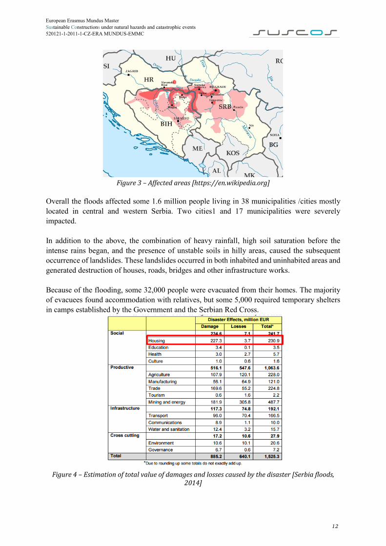
Overall the floods affected some 1.6 million people living in 38 municipalities /cities mostly located in central and western Serbia. Two cities1 and 17 municipalities were severely impacted. In addition to the above, the combination of heavy rainfall, high soil saturation before the intense rains began, and the presence of unstable soils in hilly areas, caused the subsequent occurrence of landslides. These landslides occurred in both inhabited and uninhabited areas and generated destruction of houses, roads, bridges and other infrastructure works. Because of the flooding, some 32,000 people were evacuated from their homes. The majority of evacuees found accommodation with relatives, but some 5,000 required temporary shelters in camps established by the Government and the Serbian Red Cross.
Figure 4 – Estimation of total value of damages and losses caused by the disaster [Serbia floods,
2014]
12

European Erasmus Mundus Master Sustainable Constructions under natural hazards and catastrophic events 520121-1-2011-1-CZ-ERA MUNDUS-EMMC In reaction to the severe flooding and ensuing landslides, on 15 May the Government of Serbia declared a state of emergency for its entire territory. At the same time, in order to maximize the effectiveness of the response to the emergency, a request for assistance was sent to the international community. Many countries and international organizations have offered to provide relief. Mostly provided help comprised of rescue teams, financial donations, generators and pumps, rescue boats and vehicles, and so on. However, solutions of sheltering for affected population was provided only by a few countries by means of common tents. More than 20000 of people around Balkan countries were in need for an urgent solution of sheltering. People affected by flooding were placed on camps provided by Red Cross.
Figure 5 - Number of damaged houses [Serbia floods, 2014]
Recovery needs in the housing sector include financing of temporary accommodations for those households whose homes have been destroyed or require considerable repairs, over a period of 6 months; the cost of demolition and debris and mud removal; the rescheduling of outstanding non-performing loans of the home owners; and the urgent replacement of essential household goods. This disaster showed the unpreparedness of countries to this kind of emergencies. It can be observed that solution for sheltering is an important issue after disaster and should be designed and produced in advance in order to be ready for use immediately after disaster strikes.
1.3 EM-ARCH PROJECT PROPOSAL OVERVIEW EM-ARCH proposes an innovative, complex and systematic approach to emergency situations, including the necessary measures and appropriate technologies which provide safety, comfort and minimal living standards for those affected by disaster. The project will comprise of the design of a modular, reconfigurable system, made of temporary living quarters, sanitary and food processing facilities, and all necessary utility modules that produce electrical and thermal energy, drinking/domestic water, and ensure the wastewater treatment (Figure 6). The system will be designer for easy storage, fast deployment and assembling, and can be removed and recycled after the restoration of normal living conditions. This system needs to be
13

European Erasmus Mundus Master Sustainable Constructions under natural hazards and catastrophic events 520121-1-2011-1-CZ-ERA MUNDUS-EMMC acquired and stored near to the emergency situations potential zones, in coordination with the nature of the possible crisis type and estimated affected persons.
Figure 6 – EM ARCH system proposal:
1 – Module of 1 room; 2 – Common space modules, 3 – Storage, 4 – Module of 3 rooms; 5 – Heating unit; 6 – Energy supply unit; 7,8 – Water supply units.
All research results will be implemented in an experimental, ready to use model, useful especially for testing the proposed solutions and the results dissemination. The solution proposed by EM-ARCH project consists in offering independent temporary living complexes for disaster victims, so that during the time of temporary relocation of inhabitants the original damaged localities can be rebuilt with the aid of a team of professionals.
14

European Erasmus Mundus Master Sustainable Constructions under natural hazards and catastrophic events 520121-1-2011-1-CZ-ERA MUNDUS-EMMC
1.4 GENERAL DESCRIPTION OF MODULES The temporary buildings are prefabricated modular units that can be fast assembled to construct a complex system with minimum living facilities and adequate living spaces. Each module has access to the elements enumerated below, ensuring the basic needs of a person. The needed facilities are: shelter of wind and rain, interior comfort conditions like: hygiene, proper lightning and minimum living space. Common facilities include: sufficient quantity of water and food for each person, medical assistance, storage of the equipment, equipment for communication with partners, access to information and access to public transportation. The assembly includes also logistics, equipment and personnel for the installation of a base of operations and for starting the mission, from the earliest stage possible. The integrated furniture is designed as ergonomically as possible. It should be easily adapted in order to enhance space. Furniture also integrates in some cases built-in utilities (e.g. fittings and electrical wires in the case of the medical modules). Cables and pipes for water supply and water sewage – specific to each container are also integrated in furniture or in enclosure elements such as walls and floors. The project is aimed to study an integrated system of buildings by using prefabricated 3D modules integrating the assembling technology and built-in utilities (Figure 7).
Figure 7 – Overall view of 3D unit [EM-ARCH Project Proposal]
The off-site prefabrication of elements leads to a fast pace of on-site building, a quality enhancement and the reduction of resources and losses. For the building of post-disaster dwellings, prefabricated modular structures become essential, in order to meet the post-disaster needs rapidly. The modular steel structural system was considered here for several advantages: prefabrication and modularity, safety and functionality in execution, efficiency in design and use of material resources, reduced impact on the environment, small percentage of residual materials from the
15

European Erasmus Mundus Master Sustainable Constructions under natural hazards and catastrophic events 520121-1-2011-1-CZ-ERA MUNDUS-EMMC construction process, high-recyclability of used materials, easy dismantling and re-using of modules or of the structural elements and also internal adaptability. The project suggests an advanced technology of prefabrication and of the assembling modular units, with the following elements of innovative contribution: x�the work is done in an off-site supervised environment 80% of the time, and 20% on site, saving manufacturing costs and assembling time; x�using off-site prefabrication allows the use of numerically controlled tools and integrated CAD software; x�functionally, the modules will be made as separate structures for common spaces and for bedrooms. Due to the fact that research is performed in Romania, modules will be designed for conditions of capital of Romania – Bucharest. Bucharest belongs to Cfb climate class according to Köppen-Geiger classification. The climate is cold and temperate, with significant amount of rainfall during the year.
Figure 8 - European map of Köppen-Geiger climate classification [http://koeppen-geiger.vu-wien.ac.at/]
16

European Erasmus Mundus Master Sustainable Constructions under natural hazards and catastrophic events 520121-1-2011-1-CZ-ERA MUNDUS-EMMC
1.4.1 Structure The elements of the module are made of steel. Modules are designed in two types of section – tubular and thin-walled. Description of envelope solutions is given in following Table 1 – Types of structural solutions Table 1.
Table 1 – Types of structural solutions
The bracing was introduced in the SAP models. Introduced bracing has a circular cross-section of 6 mm diameter of S350. Given bracing is not a real bracing, it introduces the effect of shear walls. The tests performed in UPT, Romania has shown that external steel sheeting and OSB panel have the same effect as 6 mm of bracing. [Ungureanu, V., Fulop, L.A. et al, 2011].
Tubular Thin-walled
17

European Erasmus Mundus Master Sustainable Constructions under natural hazards and catastrophic events 520121-1-2011-1-CZ-ERA MUNDUS-EMMC
1.4.2 Foundations
Figure 9 – Solutions for foundation system [WHAT IF NYC..?, 2010]
1.4.3 Envelope For envelope solutions most commonly used in light modular housing were chosen. As insulation material mineral wool and Rockwool were chosen due to their mechanical and physical characteristics. Description of envelope solutions is given in following tables (Table 2, Table 3).
Table 2 – Envelope solutions - walls Type of wall Materials Thickness/density
Light steel panel with Rockwool
OSB (mm) 13
ROCKWOOL (mm) 120
Gypsum board (mm) 15
LWS (kg/m2) 15
Light steel panel with mineral wool
OSB (mm) 13
Min. wool (mm) 120
Gypsum board (mm) 15
LWS (kg/m2) 15
18
European Erasmus Mundus Master Sustainable Constructions under natural hazards and catastrophic events 520121-1-2011-1-CZ-ERA MUNDUS-EMMC
Table 3– Envelope solutions – floor and roof Type of Roof Materials Thickness/density Light steel panel with EPS
OSB (mm) 18 Insulation (mm) 120 LWS (kg/m2) 14
Gypsum board (mm) 15
Type of Floor Materials Thickness/density
OSB (mm) 18 Air cavity (mm) 80 Insulation (mm) 40 LWS (kg/m2) 14
Gypsum board (mm) 15
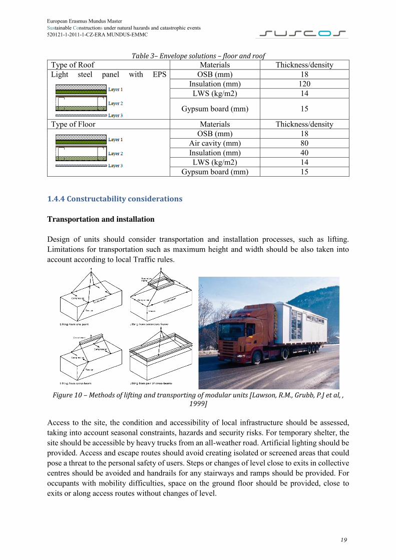
1.4.4 Constructability considerations Transportation and installation Design of units should consider transportation and installation processes, such as lifting. Limitations for transportation such as maximum height and width should be also taken into account according to local Traffic rules.
Figure 10 – Methods of lifting and transporting of modular units [Lawson, R.M., Grubb, P.J et al, ,
1999]
Access to the site, the condition and accessibility of local infrastructure should be assessed, taking into account seasonal constraints, hazards and security risks. For temporary shelter, the site should be accessible by heavy trucks from an all-weather road. Artificial lighting should be provided. Access and escape routes should avoid creating isolated or screened areas that could pose a threat to the personal safety of users. Steps or changes of level close to exits in collective centres should be avoided and handrails for any stairways and ramps should be provided. For occupants with mobility difficulties, space on the ground floor should be provided, close to exits or along access routes without changes of level.
19
European Erasmus Mundus Master Sustainable Constructions under natural hazards and catastrophic events 520121-1-2011-1-CZ-ERA MUNDUS-EMMC
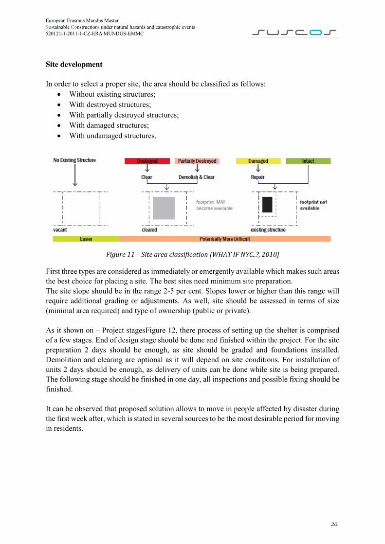
Site development In order to select a proper site, the area should be classified as follows:
x Without existing structures; x With destroyed structures; x With partially destroyed structures; x With damaged structures; x With undamaged structures.
Figure 11 – Site area classification [WHAT IF NYC..?, 2010]
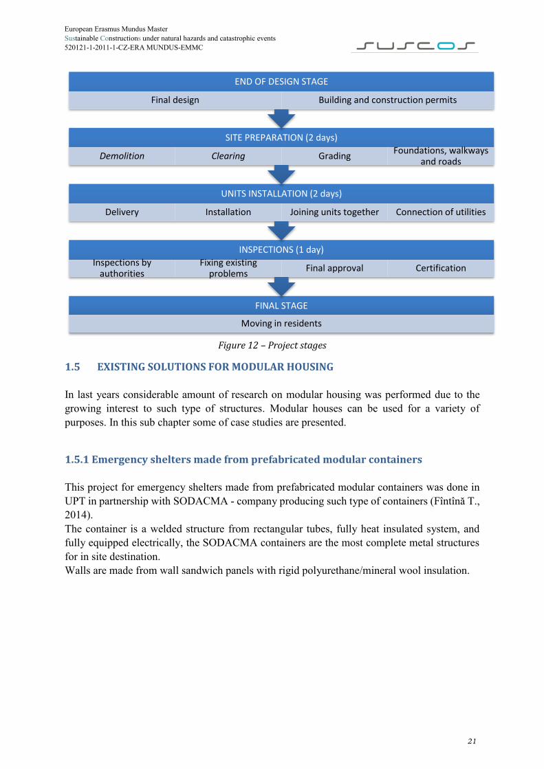
First three types are considered as immediately or emergently available which makes such areas the best choice for placing a site. The best sites need minimum site preparation. The site slope should be in the range 2-5 per cent. Slopes lower or higher than this range will require additional grading or adjustments. As well, site should be assessed in terms of size (minimal area required) and type of ownership (public or private). As it shown on – Project stagesFigure 12, there process of setting up the shelter is comprised of a few stages. End of design stage should be done and finished within the project. For the site preparation 2 days should be enough, as site should be graded and foundations installed. Demolition and clearing are optional as it will depend on site conditions. For installation of units 2 days should be enough, as delivery of units can be done while site is being prepared. The following stage should be finished in one day, all inspections and possible fixing should be finished. It can be observed that proposed solution allows to move in people affected by disaster during the first week after, which is stated in several sources to be the most desirable period for moving in residents.
20
European Erasmus Mundus Master Sustainable Constructions under natural hazards and catastrophic events 520121-1-2011-1-CZ-ERA MUNDUS-EMMC
Figure 12 – Project stages
1.5 EXISTING SOLUTIONS FOR MODULAR HOUSING In last years considerable amount of research on modular housing was performed due to the growing interest to such type of structures. Modular houses can be used for a variety of purposes. In this sub chapter some of case studies are presented.
1.5.1 Emergency shelters made from prefabricated modular containers This project for emergency shelters made from prefabricated modular containers was done in UPT in partnership with SODACMA - company producing such type of containers (Fîntînă T., 2014). The container is a welded structure from rectangular tubes, fully heat insulated system, and fully equipped electrically, the SODACMA containers are the most complete metal structures for in site destination. Walls are made from wall sandwich panels with rigid polyurethane/mineral wool insulation.
FINAL STAGE
Moving in residents
INSPECTIONS (1 day)Inspections by
authoritiesFixing existing
problems Final approval Certification
UNITS INSTALLATION (2 days)
Delivery Installation Joining units together Connection of utilities
SITE PREPARATION (2 days)
Demolition Clearing Grading Foundations, walkways and roads
END OF DESIGN STAGE
Final design Building and construction permits
21

European Erasmus Mundus Master Sustainable Constructions under natural hazards and catastrophic events 520121-1-2011-1-CZ-ERA MUNDUS-EMMC
Figure 13 – Emergency shelter [Fîntînă T., 2014]
1.5.2 Affordable house project This project for Affordable housing was done in LTU, Sweden. The aim of the project was to design an affordable building made of steel to meet primarily needs of students accommodation at Swedish university campus area and at Luleå University of Technology Campus in particular (Veljkovic M., 2010). Columns and beams are I profile and are integrated into the structure and welded to fix the structure.
Figure 14 – Student Affordable housing modules [Veljkovic M., 2010]
Figure 15 – Affordable housing project [Veljkovic M., 2010]
22
European Erasmus Mundus Master Sustainable Constructions under natural hazards and catastrophic events 520121-1-2011-1-CZ-ERA MUNDUS-EMMC
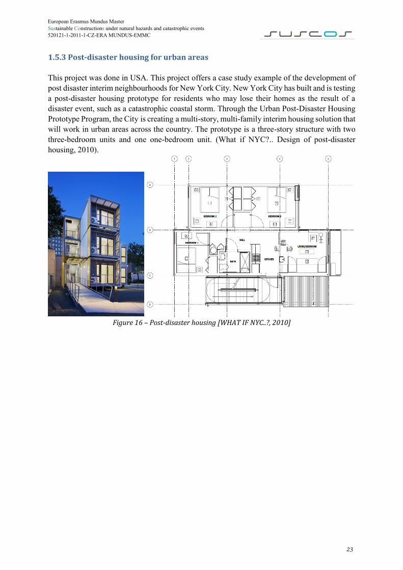
1.5.3 Post-disaster housing for urban areas This project was done in USA. This project offers a case study example of the development of post disaster interim neighbourhoods for New York City. New York City has built and is testing a post-disaster housing prototype for residents who may lose their homes as the result of a disaster event, such as a catastrophic coastal storm. Through the Urban Post-Disaster Housing Prototype Program, the City is creating a multi-story, multi-family interim housing solution that will work in urban areas across the country. The prototype is a three-story structure with two three-bedroom units and one one-bedroom unit. (What if NYC?.. Design of post-disaster housing, 2010).
Figure 16 – Post-disaster housing [WHAT IF NYC..?, 2010]
23

European Erasmus Mundus Master Sustainable Constructions under natural hazards and catastrophic events 520121-1-2011-1-CZ-ERA MUNDUS-EMMC
CHAPTER 2 - STRUCTURAL ANALYSIS AND DESIGN
2.1 OVERVIEW Structural design was made according to Eurocode in the ultimate and serviceability limit states. Models were done in SAP2000 in order to perform 3D analysis of the structure. In order to compare different alternatives 6 models were created – one, two and three storey solutions made of hollow section members and thin-walled members.
2.2 MATERIALS For 2 different models different types of steel were used as shown in Table 4.
Table 4 – Materials description
Model of hollow section members
Model of thin-walled members
S275 (EN10025-2) S350GD+Z (EN 10326) Properties
𝑓𝑦, 𝑀𝑃𝑎 275 350 𝑓𝑢, 𝑀𝑃𝑎 430 420 𝐸, 𝑀𝑃𝑎 210000 𝐺, 𝑀𝑃𝑎 81000
2.3 QUANTIFICATION OF LOADS The quantification of the actions and their combinations was made according to EN 1990 (2002), EN 1991-1-1 (2002), EN 1991-1-3 (2003), EN 1991-1-4 (2005) and P100-1-2013, considering the permanent actions that correspond to the self-weight of the structure and non-structural members, the variable actions corresponding to imposed loads, snow, wind and the accidental actions as earthquakes.
2.3.1 Permanent load In quantifying the permanent actions, not only is the self-weight of structural members considered, but also the self-weight of the purlins and that of the roof sheeting, which are estimated as 1.0 𝑘𝑁
𝑚2.
24

European Erasmus Mundus Master Sustainable Constructions under natural hazards and catastrophic events 520121-1-2011-1-CZ-ERA MUNDUS-EMMC
2.3.2 Imposed load The imposed load is given according to EN 1991-1-1. Considering that the floor is A category – areas for domestic and residential activities, the characteristic value of the uniformly distributed imposed load 𝑞𝑘 must be 1.5. .2.0 𝑘𝑁
𝑚2, in horizontal plan (clause 6.3.1.2). In this case,
taking a value of 𝑞𝑘 = 2.0 𝑘𝑁𝑚2.
2.3.3 Snow load According to EN 1991-1-3, the quantification of the snow action is given by (clause 5.2.):
𝑆 = 𝜇1𝐶𝑒𝐶𝑡𝑠𝑘𝛾𝐼𝑠 Where: 𝜇1 is the snow load shape coefficient (Figure 5.1 -5.3.2); since 0° < 𝛼 < 30°, 𝜇1 = 0.8; 𝐶𝑒 is the exposure coefficient, 𝐶𝑒 = 1.0; 𝐶𝑡 is the thermal coefficient, 𝐶𝑡 = 1.0; 𝛾𝐼𝑠 is the importance coefficient, for temporary structures – class 4, γIs = 1.0 sk is the characteristic value of the snow action, at the level of the ground, 𝑠𝑘 = 2 𝑘𝑁/𝑚2 for Bucharest. For monopitch roof only one snow load scheme is considered – uniform snow load over the whole roof (Figure 17).
Figure 17 – Snow load shape coefficient – monopitch roof
25

European Erasmus Mundus Master Sustainable Constructions under natural hazards and catastrophic events 520121-1-2011-1-CZ-ERA MUNDUS-EMMC
Figure 18 – Characteristic values of snow load on ground, kN/m2, for altitude less 1000 m
S = 0.8 ∙ 1 ∙ 1 ∙ 2 ∙ 1 = 1.6 kN/m2
2.3.4 Wind load In order to quantify wind loads following algorithm presented in EN 1991-1-4 is shown in Table 5.
Table 5 – Calculation procedures for the determination of wind actions
26

European Erasmus Mundus Master Sustainable Constructions under natural hazards and catastrophic events 520121-1-2011-1-CZ-ERA MUNDUS-EMMC According to EN-1991-1-4, the wind loads on the building is given by following expressions: For external forces:
Fw,e = cscd ∑ wesurf
∙ Aref
For internal forces:
Fw,e = ∑ wisurf
∙ Aref
cscd − is the structural factor, as defined in 6.2.1 (a) it can be taken equal to 1 for buildings with height less than 15 m; Aref − is the reference area of the individual surface; we − is the external pressure of the individual surface at height ze, given by (5.1)
we = qp(ze)cpe wi − is the internal pressure of the individual surface at height zi, given by (5.2)
we = qp(zi)cpi qp − is the peak velocity pressure; z − is the reference height for the external or internal pressure; cpe − is the pressure coefficient for the external pressure, cpi − is the pressure coefficient for the internal pressure. The peak velocity pressure is given by (4.8):
qp = ce(z)qb = 2.1 ∙ 0.5 = 1.05 kN/m2 ce − is the exposure factor, for height of 2.8, for terrain category I (lakes or flat and horizontal area with negligible vegetation and without obstacles) can be taken from the following Figure 19 equal to 2.1;
Figure 19 – Exposure factor, 𝑐𝑒(𝑧)
qb − is the basic velocity pressure of wind,
27

European Erasmus Mundus Master Sustainable Constructions under natural hazards and catastrophic events 520121-1-2011-1-CZ-ERA MUNDUS-EMMC
Figure 20 - Characteristic values of wind load, kN/m2
qb = 0.5kPa for Bucharest. External pressure coefficients Pressure zones on the walls
Figure 21 – Pressure zones on the walls
For the rectangular plan building external pressure coefficients will be taken from the Figure 21 and Table 6.
28

European Erasmus Mundus Master Sustainable Constructions under natural hazards and catastrophic events 520121-1-2011-1-CZ-ERA MUNDUS-EMMC
Table 6 – Recommended values of external pressure coefficients for vertical walls of rectangular plan buildings
For the design of buildings as external pressure coefficients, cpe,10 coefficients are used:
Table 7 - External pressure coefficients A B C D E
𝜃 = 0° -1.20 -0.80 -0.50 +0.80 -0.50 𝜃 = 90° -1.20 -0.80 -0.50 +0.73 -0.36
Pressure zones on the roof
Figure 22 – Pressure zones on the roof
For the design of flat roof with sharp eaves buildings as internal pressure coefficients, cpe,10 coefficients are used:
Table 8 - Internal pressure coefficients F G H I
θ = 0° -1.8 -1.2 -0.7 ±0.2 θ = 90° -1.8 -1.2 -0.7 ±0.2
Due to small area of the roof only one case will be considered – uniform suction on the roof with cpe,10 = −1.8.
29

European Erasmus Mundus Master Sustainable Constructions under natural hazards and catastrophic events 520121-1-2011-1-CZ-ERA MUNDUS-EMMC Internal pressure coefficients The internal pressure coefficients,𝑐𝑝𝑖, depend on the size and distribution of the openings in the building envelope. For buildings without a dominant face and where it is not possible to determine the number of openings, then 𝑐𝑝𝑖 should be taken as the more onerous of +0.2 and -0.3. Final pressure coefficients The most unfavourable situation is considered for each direction of the wind, leading to the final pressure coefficients (Figure 23, Table 9).
Table 9 – Final pressure coefficients A B C D E F
𝜃 = 0° -1.50 -1.10 -0.80 +1.00 -0.80 -2.1 𝜃 = 90° -1.50 -1.10 -0.80 +0.93 -0.66 -2.1
Figure 23 – Schemes for pressure coefficients for walls and roof
30

European Erasmus Mundus Master Sustainable Constructions under natural hazards and catastrophic events 520121-1-2011-1-CZ-ERA MUNDUS-EMMC
2.3.5 Seismic load A reference peak ground acceleration (Figure 24) for Bucharest equal to agR = 0.3g.
Figure 24 – Reference peak ground acceleration
Figure 25 – Values of Tc period for response spectrum
Table 10 – Values of periods for different zones
𝑇𝐵, 𝑠 0.14 0.2 0.32 𝑇𝐶, 𝑠 0.7 1.0 1.6 𝑇𝐷, 𝑠 3.0 3.0 2.0
For Bucharest (from Table 10): 𝑇𝐵 = 0.32 𝑠
31

European Erasmus Mundus Master Sustainable Constructions under natural hazards and catastrophic events 520121-1-2011-1-CZ-ERA MUNDUS-EMMC
𝑇𝐶 = 1.6 𝑠 𝑇𝐷 = 2.0 𝑠 Spectrum:
Figure 26 – Elastic response spectrum
Table 11 – Values of elastic response spectrum
T, s Se, m/s2 T, s Se, m/s2 T, s Se, m/s2 T, s Se, m/s2 0 2.943 2.2 4.864 3.2 2.299 4.1 1.401
0.1 4.323 2.3 4.451 3.25 2.229 4.2 1.335 0.2 5.702 2.4 4.088 3.3 2.162 4.3 1.273 0.3 7.082 2.5 3.767 3.4 2.037 4.4 1.216 1.6 7.358 2.6 3.483 3.5 1.922 4.5 1.163 1.7 6.925 2.7 3.230 3.6 1.817 4.6 1.113 1.8 6.540 2.8 3.003 3.7 1.720 4.7 1.066 1.9 6.196 2.9 2.800 3.8 1.630 4.8 1.022 2 5.886 3 2.616 3.9 1.548 4.9 0.981
2.1 5.339 3.1 2.450 4 1.472 5 0.942
0.00
1.00
2.00
3.00
4.00
5.00
6.00
7.00
8.00
0.00 1.00 2.00 3.00 4.00 5.00 6.00
Se(T
), m
/s2
T, s
Spectrum
Spectrum
32

European Erasmus Mundus Master Sustainable Constructions under natural hazards and catastrophic events 520121-1-2011-1-CZ-ERA MUNDUS-EMMC
2.3.6 Load combinations The rules and methods for the definition of the load combination are given in Annex A1 of EN 1990.
The recommended values of the reduction factors 𝜓 for the actions considered as follows (Table 12).
Table 12 – Reduction factor values Type of action 𝜓0 𝜓1 𝜓2 Imposed loads in buildings cat. A 0.7 0.5 0.3 Snow loads on buildings 0.5 0.2 0 Wind loads on buildings 0.6 0.2 0
𝛾𝐺 = 1.35; 𝛾𝐺 = 1.5
Table 13 – Load combinations Comb. Perm. Snow Wind long. Wind tr. Live Seismic 1 1.35 1.5 2 1.35 1.5 3 1.35 1.5 4 1.35 1.5 5 1.35 1.5 1.05 6 1.35 1.5 1.05 7 1.35 1.5 1.05 8 1.35 1.05 1.5 9 1.35 1.05 1.5 10 1.35 1.05 1.5 11 1.35 1.5 0.9 1.05 12 1.35 1.5 0.9 1.05 13 1.00 0.4 0.4 1.0 14 1.35 1.5 1.05 15 1.35 1.05 1.5 16 1.35 1.5 1.05 17 1.35 1.05 1.5
33

European Erasmus Mundus Master Sustainable Constructions under natural hazards and catastrophic events 520121-1-2011-1-CZ-ERA MUNDUS-EMMC
2.4 DESIGN OF STRUCTURAL ELEMENTS
2.4.1 Model of hollow section members For this type of models design was made for columns, transversal and longitudinal beams, connections. Design for bracing was not carried out, however bracing was introduced in the SAP models. Introduced bracing has a circular cross-section of 6 mm diameter of S350. Given bracing is not a real bracing, it introduces the effect of shear walls. The tests performed in UPT, Romania has shown that external steel sheeting and OSB panel have the same effect as 6 mm of bracing. [Ungureanu, V., Fulop, L.A. et al, 2011].
2.4.1.1 Column
1. Cross section classification 2. Verification of cross section resistance
𝑁𝐸𝑑
𝑁𝑅𝑑+
𝑀𝑦,𝐸𝑑
𝑀𝑦,𝑅𝑑+
𝑀𝑧,𝐸𝑑
𝑀𝑧,𝑅𝑑≤ 1.0
3. Verification of the stability of the member 𝑁𝐸𝑑
𝜒𝑦𝑁𝑅𝑑+ 𝑘𝑦𝑦
𝑀𝑦,𝐸𝑑
𝜒𝐿𝑇𝑀𝑦,𝑅𝑑≤ 1.0
𝑁𝐸𝑑
𝜒𝑧𝑁𝑅𝑑+ 𝑘𝑧𝑦
𝑀𝑦,𝐸𝑑
𝜒𝐿𝑇𝑀𝑦,𝑅𝑑≤ 1.0
4. Verification of damage limitation criteria 𝜈𝑑𝑟 < 𝑎ℎ 𝜈 = 0.5
𝑎 = 0.0075 ℎ = 2800 𝑚𝑚
0.5𝑑𝑟 < 21 𝑚𝑚
Table 14 – Results for columns (cross section, ratios) Single level
model Double level model
Triple level model
Cross section SHS 90*7.1 SHS 100*10 SHS 140*14.2 CS class Class 1 Class 1 Class 1 CS resistance 0.48 0.46 0.43 Stability 0.49 0.75 0.89 Damage limitation, 0.5𝑑𝑟, 𝑚𝑚 5 15.5 17.5
Choice of cross section in single level model is due to the need to arrange moment resisting welded connections.
34

European Erasmus Mundus Master Sustainable Constructions under natural hazards and catastrophic events 520121-1-2011-1-CZ-ERA MUNDUS-EMMC
2.4.1.2 Beams
1. Cross section classification 2. Verification of cross section resistance
𝑀𝐸𝑑
𝑀𝑝𝑙,𝑅𝑑≤ 1.0
3. Verification of the stability of the member 𝑁𝐸𝑑
𝜒𝑦𝑁𝑅𝑑+ 𝑘𝑦𝑦
𝑀𝑦,𝐸𝑑
𝜒𝐿𝑇𝑀𝑦,𝑅𝑑≤ 1.0
𝑁𝐸𝑑
𝜒𝑧𝑁𝑅𝑑+ 𝑘𝑧𝑦
𝑀𝑦,𝐸𝑑
𝜒𝐿𝑇𝑀𝑦,𝑅𝑑≤ 1.0
4. Verification of serviceability criteria
𝛿 =5
384𝑞𝑠𝐿4
𝐸𝐼 ≤ 𝛿𝑀𝐴𝑋 =𝐿
360 𝛿
𝛿𝑀𝐴𝑋≤ 1.0
Table 15 – Results for beams Single level model Double level model Triple level model Type of beam Transv. Long. Transv. Long. Transv. Long. Cross section SHS
80*5.4 SHS
60*3.6 RHS
90*63*10 SHS
60*3.6 RHS
140*70*12.5 SHS
60*3.6 CS class Class 1 CS resistance 0.81 0.51 0.73 0.13 0.88 0.13 Stability 0.80 0.60 0.42 0.15 0.36 0.15 Serviceability 0.97 0.1 0.56 0.1 0.15 0.1
2.4.1.3 Connections Transversal beam-to-column welded connection
Figure 27 - Beam-to-column welded connection
Table 16 – Results for transversal beam-to-column welded connection
Single level model Double level model Triple level model Stiffness, kNm 2141.8 4996.5 7152.1 Moment resistance, kNm 9.64 14.76 22.43 Joint classification Rigid Rigid Rigid
35

European Erasmus Mundus Master Sustainable Constructions under natural hazards and catastrophic events 520121-1-2011-1-CZ-ERA MUNDUS-EMMC
Longitudinal beam-to-column welded connection
Table 17 - Results for longitudinal beam-to-column welded connection Single level model Double level model Triple level model Stiffness 3398.6 3332.3 7364.5 Moment resistance 4.3 4.3 4.3 Joint classification Rigid Rigid Rigid
Column splice connection In order to represent more adequate model behaviour partial fixity of column splices was introduced in the model. For each connection stiffness was evaluated in STEELCON Software using analogic (equivalent) cross sections.
Figure 28 – Column splice connection details and equivalent model from STEELCON
Table 18 – Results for column splice connection
Double level model Triple level model
Description Plate 200*200*15 4 bolts M16 8.8
Plate 250*250*20 4 bolts M16 8.8
Stiffness, kNm 4210.8 7092.9 Moment resistance, kNm 18.63 27.65 Joint classification Semi-rigid Semi-rigid Ratio 0.26 0.51
36

European Erasmus Mundus Master Sustainable Constructions under natural hazards and catastrophic events 520121-1-2011-1-CZ-ERA MUNDUS-EMMC
Figure 29 – Classification boundaries for column splice joint
Choice of bolts is based on availability of such bolts on the market. Module in-plan connection To assure joint action of modules in-plan connections are needed. Two solutions are proposed:
x Connection with tie; x Connection with welded angles.
Connection with tie (Figure 30) – tie is put on plates and bolted after installation of modules on site.
Figure 30 – Connection with tie
Connection with angles (Figure 31) – angles are welded to columns in workshop and after installation are bolted together on site.
37

European Erasmus Mundus Master Sustainable Constructions under natural hazards and catastrophic events 520121-1-2011-1-CZ-ERA MUNDUS-EMMC
Figure 31 – Connection with angles
These connections are just a proposal based on solutions used for temporary connection of shipping containers during transportation.
38

European Erasmus Mundus Master Sustainable Constructions under natural hazards and catastrophic events 520121-1-2011-1-CZ-ERA MUNDUS-EMMC
2.4.1.4 Modes of vibration
Table 19 – Modes of vibration for 1 level model Mode 1, T=0.33 s Mode 2, T=0.27 s
Mode 3, T=0.14 s Mode 4, T=0.11 s
Table 20 - Modes of vibration for 2 levesl model Mode 1, T=0.46 s Mode 2, T=0.43 s
Mode 3, T=0.28 s Mode 4, T=0.18 s
39

European Erasmus Mundus Master Sustainable Constructions under natural hazards and catastrophic events 520121-1-2011-1-CZ-ERA MUNDUS-EMMC
Table 21 - Modes of vibration for 3 levels model
Mode 1, T=0.53 s Mode 2, T=0.49 s
Mode 3, T=0.44 s Mode 4, T=0.17 s
2.4.1.5 Summary of results
Table 22 – Overall weights for chosen solutions Single level
model Double level model
Triple level model
Column, kg 292.3 651.8 1512 Transversal beam, kg 169.5 540 1377 Longitudinal beam, kg 142.8 285.6 428.4 Additional materials (bolts, plates, etc.) = 25% of weight, kg
151.6 369.4 829.1
Total weight, kg 756.2 1846.8 4146.5 Weight per 1 module, kg 756.2 923.4 1382.2
40

European Erasmus Mundus Master Sustainable Constructions under natural hazards and catastrophic events 520121-1-2011-1-CZ-ERA MUNDUS-EMMC
2.4.2 Model of thin walled members For this type of models design was made for columns, transversal and longitudinal beams, connections. Design for bracing was not carried out, however bracing was introduced in the SAP models. Introduced bracing has a circular cross-section of 6 mm diameter of S350. Given bracing is not a real bracing, it introduces the effect of shear walls. The tests performed in UPT, Romania has shown that external steel sheeting and OSB panel have the same effect as 6 mm of bracing. [Ungureanu, V., Fulop, L.A. et al, 2011].
2.4.2.1 Column
1. Cross section classification 2. Verification of cross section resistance
𝑁𝐸𝑑
𝑁𝑐,𝑅𝑑+
𝑀𝑦,𝐸𝑑
𝑀𝑦𝑐,𝑅𝑑≤ 1.0
𝑁𝑐,𝑅𝑑 =𝐴𝑒𝑓𝑓𝑓𝑦𝑏
𝛾𝑀0
𝑀𝑦𝑐,𝑅𝑑 =𝑊𝑒𝑓𝑓𝑓𝑦𝑏
𝛾𝑀0
3. Verification of the stability of the member 𝑁𝐸𝑑
𝜒𝑦𝑁𝑅𝑑+ 𝑘𝑦𝑦
𝑀𝑦,𝐸𝑑
𝜒𝐿𝑇𝑀𝑦,𝑅𝑑≤ 1.0
𝑁𝐸𝑑
𝜒𝑧𝑁𝑅𝑑+ 𝑘𝑧𝑦
𝑀𝑦,𝐸𝑑
𝜒𝐿𝑇𝑀𝑦,𝑅𝑑≤ 1.0
𝑁 𝑅𝑑 =𝐴𝑒𝑓𝑓𝑓𝑦𝑏
𝛾𝑀1
𝑀𝑦,𝑅𝑑 =𝑊𝑒𝑓𝑓𝑓𝑦𝑏
𝛾𝑀1
4. Verification of damage limitation criteria 𝜈𝑑𝑟 < 𝑎ℎ 𝜈 = 0.5
𝑎 = 0.0075 ℎ = 2800 𝑚𝑚
0.5𝑑𝑟 < 21 𝑚𝑚
Table 23 – Results for columns Single level
model Double level
model Triple level
model Cross section 2*C120*1 2*C120*1.2 2*C120*2 Cross section classification Class 4 Class 4 Class 4 Cross section resistance 0.2 0.6 0.51 Stability of the member 0.26 0.85 0.78 Damage limitation, 0.5𝑑𝑟, 𝑚𝑚 6 9.5 20.5
41

European Erasmus Mundus Master Sustainable Constructions under natural hazards and catastrophic events 520121-1-2011-1-CZ-ERA MUNDUS-EMMC Choice of cross section in single level model is due to the ease of arranging connection between studs and beams. 2.4.2.2 Beams
1. Cross section classification 2. Verification of cross section resistance (bending/shear)
𝑀𝑦,𝐸𝑑
𝑀𝑦𝑐,𝑅𝑑≤ 1.0
𝑀𝑦𝑐,𝑅𝑑 =𝑊𝑒𝑓𝑓𝑓𝑦𝑏
𝛾𝑀0
𝑉𝐸𝑑
𝑉𝑐,𝑅𝑑≤ 1.0
𝑉𝑐,𝑅𝑑 = min [ℎ𝑤𝑡𝑓𝑦𝑏
𝛾𝑀0√3 𝑠𝑖𝑛 𝜑;
ℎ𝑤𝑡𝑓𝑏𝑣
𝛾𝑀0 𝑠𝑖𝑛 𝜑]
3. Verification of the local transverse resistance 𝑉𝐸𝑑
𝑅𝑤,𝑅𝑑≤ 1.0
𝑅𝑤,𝑅𝑑 = 2 ∗ 𝑘1𝑘2𝑘3 [5.92 −ℎ𝑤 𝑡⁄132 ] [1 +
0.01𝑠𝑠
𝑡 ] 𝑡2𝑓𝑦𝑏/𝛾𝑀1
4. Verification of serviceability criteria
𝛿 =5
384𝑞𝑑,𝑠𝑒𝑟𝐿4
𝐸𝐼𝑓𝑖𝑐
Table 24 – Results for beams
Single level model Double level model Triple level model Type Transv. Long. Transv. Long. Transv. Long. CS 2*C120*1 3*U125*1.2 2*C120*1.2 3*U125*1.2 2*C120*1.5 3*U125*1.5 CS class Class 4 Bending resistance 0.64 0.49 0.87 0.29 0.53 0.35
Shear resistance 0.37 0.48 0.37 0.39 0.15 0.4
Local tr. resistance 0.84 0.88 0.92 0.89 0.92 0.88
Serviceability 0.5 0.45 0.45 0.42 0.34 0.35
42

European Erasmus Mundus Master Sustainable Constructions under natural hazards and catastrophic events 520121-1-2011-1-CZ-ERA MUNDUS-EMMC
2.4.2.3 Connections
Figure 32 – Connections between thin-walled members
Connection between stud and upper rail of longitudinal beam was designed. For intermediate studs made of single channel 4 screws are needed. For main studs made of double channel and upper rail 16 screws are needed.
Figure 33 – Scheme of stud to rail connection
The following conditions should be satisfied:
𝑒1 ≥ 3𝑑; 𝑝1 = 𝑝2 ≥ 3𝑑; 𝑒2 ≥ 1.5𝑑; 3.0 𝑚𝑚 < 𝑑 < 8.0 𝑚𝑚 Bearing resistance:
𝐹𝑏,𝑅𝑑 =𝛼𝑓𝑢𝑑𝑡
𝛾𝑀2
𝛼 = 3.2√𝑡/𝑑 … 2.1 ~𝑜𝑛 𝑡/𝑡1 Net section resistance:
𝐹𝑛,𝑅𝑑 =𝐴𝑛𝑒𝑡𝑓𝑢
𝛾𝑀2
Shear resistance:
𝐹𝑣,𝑅𝑑 =𝐹𝑣,𝑅𝑘
𝛾𝑀2
43

European Erasmus Mundus Master Sustainable Constructions under natural hazards and catastrophic events 520121-1-2011-1-CZ-ERA MUNDUS-EMMC
Figure 34 – Connection with screws along full length of the beam
Figure 35 - Connections with angles placed along the beam
For connections between units shown on Figure 34, Figure 35 solutions can be used. Connections with angles placed along the beam – angles are bolted to the unit in factory and then bolted on site to connect units. Angles (100*50*8) can be placed on the corners or over each main stud (4 for 1 side) and bolted with 2 bolts.
44

European Erasmus Mundus Master Sustainable Constructions under natural hazards and catastrophic events 520121-1-2011-1-CZ-ERA MUNDUS-EMMC
2.4.2.5 Modes of vibration
Table 25 - Modes of vibration for 1 level model
Mode 1, T=0.27 s Mode 2, T=0.15 s
Mode 3, T=0.13 s Mode 4, T=0.10 s
Table 26 - Modes of vibration for 2 levels model
Mode 1, T=0.39 s Mode 2, T=0.23 s
Mode 3, T=0.21 s Mode 4, T=0.18 s
45

European Erasmus Mundus Master Sustainable Constructions under natural hazards and catastrophic events 520121-1-2011-1-CZ-ERA MUNDUS-EMMC
Table 27 - Modes of vibration for 3 levels model
Mode 1, T=0.64 s Mode 2, T=0.38 s
Mode 3, T=0.35 s Mode 4, T=0.25 s
2.4.2.5 Summary of results Table 28 – Overall weights for chosen solutions
Single level model
Double level model
Triple level model
Column, kg 164.2 380.2 959.1 Transversal beam, kg 228 672 1008 Longitudinal beam, kg 136.1 272.2 509.8 Additional materials (bolts, plates, etc.), kg 132.1 331.1 620.2 Total weight, kg 660.4 1655.5 3096.2 Weight per 1 module, kg 660.4 827.8 1032.1
46
European Erasmus Mundus Master Sustainable Constructions under natural hazards and catastrophic events 520121-1-2011-1-CZ-ERA MUNDUS-EMMC
2.5 INFRASTRUCTURE
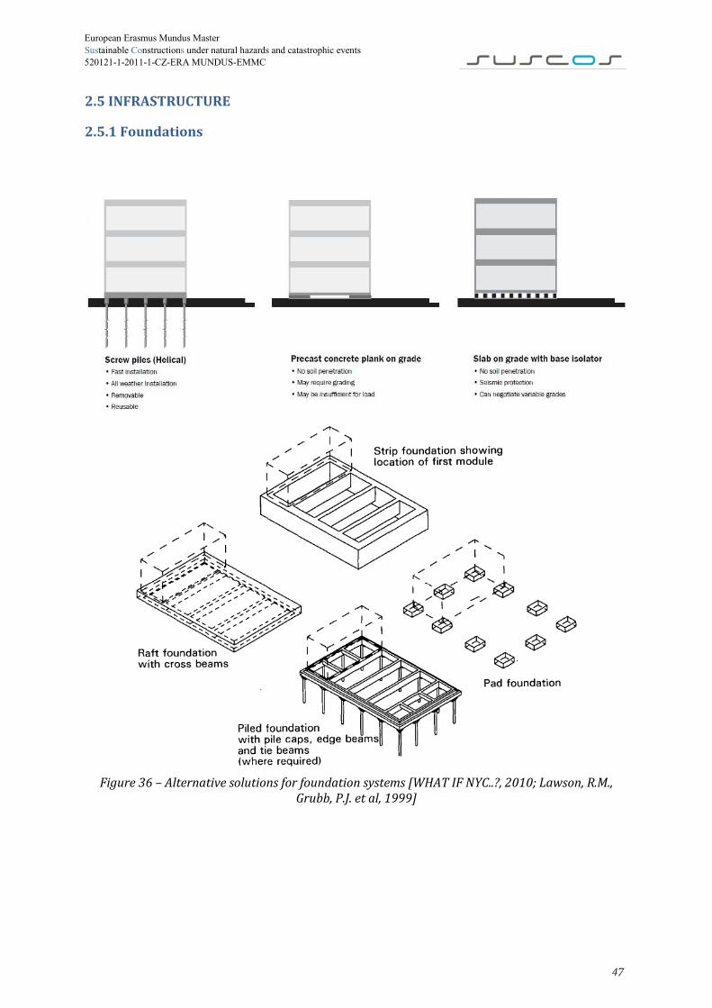
2.5.1 Foundations
Figure 36 – Alternative solutions for foundation systems [WHAT IF NYC..?, 2010; Lawson, R.M.,
Grubb, P.J. et al, 1999]
47
European Erasmus Mundus Master Sustainable Constructions under natural hazards and catastrophic events 520121-1-2011-1-CZ-ERA MUNDUS-EMMC
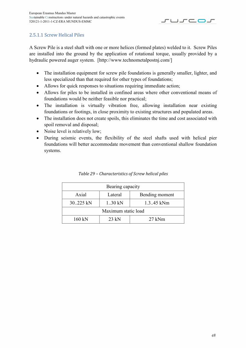
2.5.1.1 Screw Helical Piles A Screw Pile is a steel shaft with one or more helices (formed plates) welded to it. Screw Piles are installed into the ground by the application of rotational torque, usually provided by a hydraulic powered auger system. [http://www.technometalpostnj.com/]
x The installation equipment for screw pile foundations is generally smaller, lighter, and less specialized than that required for other types of foundations;
x Allows for quick responses to situations requiring immediate action; x Allows for piles to be installed in confined areas where other conventional means of
foundations would be neither feasible nor practical; x The installation is virtually vibration free, allowing installation near existing
foundations or footings, in close proximity to existing structures and populated areas. x The installation does not create spoils, this eliminates the time and cost associated with
spoil removal and disposal; x Noise level is relatively low; x During seismic events, the flexibility of the steel shafts used with helical pier
foundations will better accommodate movement than conventional shallow foundation systems.
Table 29 – Characteristics of Screw helical piles
Bearing capacity Axial Lateral Bending moment
30..225 kN 1..30 kN 1.3..45 kNm Maximum static load
160 kN 23 kN 27 kNm
48

European Erasmus Mundus Master Sustainable Constructions under natural hazards and catastrophic events 520121-1-2011-1-CZ-ERA MUNDUS-EMMC
Figure 37 – Details of Screw helical pile foundation [http://www.technometalpostnj.com/]
2.5.1.2 Precast concrete foundations
Figure 38 – Precast concrete foundation Advantages:
x easy to install; x cheapest form of foundation; x allows for ventilation and prevents condensation forming underneath the module; x Installation requires no or small amount of excavation.
49

European Erasmus Mundus Master Sustainable Constructions under natural hazards and catastrophic events 520121-1-2011-1-CZ-ERA MUNDUS-EMMC
2.5.2 Walkways and roads For roads and walkways temporary solution is proposed.
Temporary walkways is a simple, fully interlocking, compact flooring system. The pedestrian walkway system is very hardwearing and with an anti-slip layer and manufactured from recycled PVC. Walkovers can be laid on solid ground or on grass or earth.
Temporary roadways are made of HMPE plastic, are ideally suited for light and heavy traffic and can be positioned by hand.
Temporary roads and walkways in case of soft or muddy wet soils.
Figure 39 – Temporary walkways and roads Roads and pathways within settlements should provide safe, secure and all-weather access to individual dwellings and communal facilities including schools and healthcare facilities.
50

European Erasmus Mundus Master Sustainable Constructions under natural hazards and catastrophic events 520121-1-2011-1-CZ-ERA MUNDUS-EMMC
2.6 CONCLUSIONS Structural design was performed in previous chapter in accordance with current design codes – Eurocodes and National Romanian codes. All needed structural checks for columns, beams and connections were performed and results showed that required by code conditions are satisfied. Safety of proposed solutions is assured. Triple level models will be excluded from following sustainability assessment due to the inefficient use of material in this type of models and due to possible difficulties appearing due installation process. For these types of structural members (tubular and thin-walled) in the proposed grades of steel only one and two level models will be suggested for further research and application. Further numerical simulations and studies of connections between units in plan and elevation should be carried out additionally to ensure safety.
51

European Erasmus Mundus Master Sustainable Constructions under natural hazards and catastrophic events 520121-1-2011-1-CZ-ERA MUNDUS-EMMC
CHAPTER 3 – SUSTAINABILITY APPROACH
3.1 OVERVIEW
“Sustainable development meets the needs of the present without compromising the ability of future generations to meet their own needs. Sustainable development is development that delivers environmental, economic and social services to all residents of a community, without threatening the viability of the natural, built, economic and social systems upon which the delivery of these systems depend.”
The World Commission on Environment and Development, 1987
Figure 40 – Three pillars of sustainability
x Social + Economic = Equitable x Social + Environmental = Bearable x Economic + Environmental = Viable x Social + Economic+ Environmental = Sustainable
52

European Erasmus Mundus Master Sustainable Constructions under natural hazards and catastrophic events 520121-1-2011-1-CZ-ERA MUNDUS-EMMC
3.2 SOCIAL ASPECT Social sustainability is the ability of a social system, such as a country, family, or organization, to function at a defined level of social well-being and harmony indefinitely. The social aspect of sustainability focuses on balancing the needs of the individual with the needs of the group. Social aspect should be considered accounting for 3 criteria:
x Current problem; x Safety; x Comfort.
Current problem To overcome consequences of disaster or conflict, measures have been taken mainly by different national and global organisations, generally military and civil. Currently the most widely spread solution used is providing victims with shelter in common tents which do not fulfil minimal requirements of living standards. However new disaster housing should meet diverse needs of individuals and community. New solutions for emergency housing should be designed using state-of-the-art technologies and innovative approaches in order to provide variety of cost effective, rapidly installed and sustainable solutions. “Shelter is a critical determinant for survival in the initial stages of a disaster. Beyond survival, shelter is necessary to provide security and personal safety, protection from the climate and enhanced resistance to ill health and disease. It is also important for human dignity and to sustain family and community life as far as possible in difficult circumstances. Shelter and associated settlement and non-food item responses should support communal coping strategies, incorporating as much self-sufficiency and self-management into the process as possible. Any such responses should also minimise the long-term adverse impact on the environment, whilst maximising opportunities for the affected communities to maintain or establish livelihood support activities.” The Sphere book, Humanitarian Charter and Minimum Standards in Humanitarian Response, 2011 Safety Safety criteria is achieved by means of structural design. Structural design was performed in previous chapter in accordance with current design codes – Eurocodes and National Romanian codes. All needed structural checks were performed and results showed that required by code conditions are satisfied as it shown in Chapter 2. Safety of proposed solutions is assured.
53
European Erasmus Mundus Master Sustainable Constructions under natural hazards and catastrophic events 520121-1-2011-1-CZ-ERA MUNDUS-EMMC
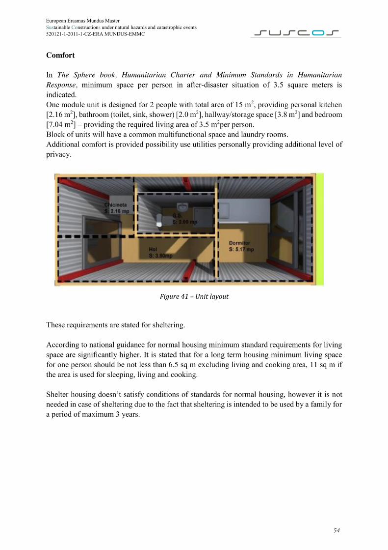
Comfort In The Sphere book, Humanitarian Charter and Minimum Standards in Humanitarian Response, minimum space per person in after-disaster situation of 3.5 square meters is indicated. One module unit is designed for 2 people with total area of 15 m2, providing personal kitchen [2.16 m2], bathroom (toilet, sink, shower) [2.0 m2], hallway/storage space [3.8 m2] and bedroom [7.04 m2] – providing the required living area of 3.5 m2per person. Block of units will have a common multifunctional space and laundry rooms. Additional comfort is provided possibility use utilities personally providing additional level of privacy.
Figure 41 – Unit layout
These requirements are stated for sheltering. According to national guidance for normal housing minimum standard requirements for living space are significantly higher. It is stated that for a long term housing minimum living space for one person should be not less than 6.5 sq m excluding living and cooking area, 11 sq m if the area is used for sleeping, living and cooking. Shelter housing doesn’t satisfy conditions of standards for normal housing, however it is not needed in case of sheltering due to the fact that sheltering is intended to be used by a family for a period of maximum 3 years.
54

European Erasmus Mundus Master Sustainable Constructions under natural hazards and catastrophic events 520121-1-2011-1-CZ-ERA MUNDUS-EMMC
3.3 ECOLOGICAL ASPECT ISO 14040:2006 and ISO 14044:2006 specify the general framework, principles and requirements for life cycle assessment. According to these standards, life cycle assessment have to consist of definition of goal and scope, inventory analysis, impact assessment and interpretation of results. Definition of goal and scope: clear statement of the intended application, the reasons for carrying out the study and the intended audience; consideration of main issues and description of the functional unit and the system boundaries; set of data collection and quality requirements. Life cycle inventory analysis: data collection and calculations in order to quantify relevant inputs and outputs of a product system. Life cycle impact assessment: quantifying of potential environmental impacts based on life cycle inventory analysis. Interpretation of results: definition of conclusions, analysis of results and choices.
Figure 42 – LCA general framework [ISO 14044:2006]
3.3.1 Life cycle impact assessment For given project LCA was carried out in SBSTEEL tool. For each solution 7 parameters were taken into account:
x GWP (tCO2eq) – global warming potential - is a relative measure of the amount of CO2
which would need to be released to have the same radiative forcing effect as a release of 1 kg of the green house gases over a particular time period. GWP is therefore a way of quantifying the potential impact on global warming of a particular gas;
x ODP (tCFCeq) – ozone depletion potential - is expressed as the global loss of ozone due to a substance compared to the global loss of ozone due to the reference substance CFC-11;
x AP (tSO2eq) – acidification potential – is measured using the ability of a substance to release H+ ions, which is the cause of acidification or it can be measured relative to an equivalent release of SO2;
55

European Erasmus Mundus Master Sustainable Constructions under natural hazards and catastrophic events 520121-1-2011-1-CZ-ERA MUNDUS-EMMC
x EP (tPO4eq) – eutrophication potential – is the enrichment of nutrients in a certain place, can be aquatic or terrestrial, leads to decrease in photosynthesis and less oxygen production;
x POCP (tEtheneeq) – is a measure of the relative ability of substance to produce ozone in the presence of NOx and sunlight., is expressed using the reference substance ethylene;
x ADP - abiotic depletion potential – aims to capture the decreasing availability of non-renewable resources as a result of their extraction and underlying scarcity:
o ADP-e (tSbeq) – abiotic depletion for elements – is determined for each extraction of elements based on the remaining reserves and rate of extraction; ADP-e is based on the equation Production/Ultimate Reserve which is compared to the reference case;
o ADP-ff (GJ NCV) – abiotic depletion – absolute measure is considered based on the energy content of the fossil fuel, doesn’t take into account the relative scarcity of different fossil fuels;
3.3.2 SBSTEEL tool The aim of this tool is to provide a quick evaluation, in the early stages of design, of the sustainability of steel-framed buildings, taking into account the life cycle environmental performance of the building, including the use stage (use of operational energy). In the early stages of design, a building designer often faces different questions in relation to: (i) the building location (which is usually not really a decision of the building designer but of the owner of the building); (ii) the building orientation; (iii) the building shape; (iv) the structural system to be adopted; (v) the building envelope and (vi) the interior finishes. Naturally, this is a challenging procedure as each question has a wide range of different alternatives that globally will lead to an even wider range of different solutions. In addition, from the point of view of the environmental assessment, the problem is more complex as one constructional solution may be beneficial in some environmental categories and simultaneously be very harmful in others. The developed approach aims to provide the building designer guidance to the above questions. Therefore, the general flowchart of the methodology is illustrated in Figure 43.
Figure 43 – General flowchart of SBSTEEL tool [SBSTEEL, Background and user guide, 2010]
56

European Erasmus Mundus Master Sustainable Constructions under natural hazards and catastrophic events 520121-1-2011-1-CZ-ERA MUNDUS-EMMC The sustainability assessment is undertaken in accordance with recent European Standards EN 15804 (2012) and EN 15978 (2011). The modular concept of the aforementioned standards, which is represented in Figure 44, is adopted in the methodology. In the tool, the life cycle environmental analysis of the building comprehends the product stage (modules A1 to A3), the construction stage (module A4, A5), the use stage (modules B1 to B7), the end-of-life stage (modules (C1 to C4) and the benefits and loads due to recycling processes (module D). However, the designer is able to select between a cradle-to-gate analysis (modules A1 to A3), a cradle-to-gate analysis plus recycling (modules A1 to A3 and module D) or a cradle-to-grave analysis plus recycling (modules A to D).
Figure 44 – Modules of a building life cycle [http://www.building.co.uk/]
3.3.3 Assessment results Life cycle impact assessment was done for Modules A, B, C and D. In the assessment materials for envelope, roof, floor and openings are included. Heating system, electrical and water appliances are excluded from analysis. Three level models were excluded from analysis after structural design stage. Life cycle impact assessment will be done for 4 solutions:
Table 30 – Envelope alternatives Alternative Levels Envelope 1 One LSP with 120 mm of Rockwool 2 One LSP with 120 mm of mineral wool 3 Two LSP with 120 mm of Rockwool 4 Two LSP with 120 mm of mineral wool
Full SBSTEEL report for one of alternatives is presented in the Annex 1. Results for all 4 alternatives comprised of environmental impacts of 7 main parameters are presented in Tables 31-34.
57

European Erasmus Mundus Master Sustainable Constructions under natural hazards and catastrophic events 520121-1-2011-1-CZ-ERA MUNDUS-EMMC
Table 31 – Environmental impact for Alternative 1
AL1 Production
Stage (A1:A3)
Construction Stage
(A4:A5)
Use Stage (B1:B7)
End-of-life Stage
(C1:C4)
Recycling Stage (D) Total
GWP, kg CO2eq 2.97E+3 4.13E+1 2.02E+2 4.40E+2 -2.65E+3 1.00E+3
ODP, kg CFCeq 1.10E-4 6.74E-6 2.18E-6 1.77E-5 -9.40E-6 1.27E-4
AP, kg SO2eq 1.55E+1 2.28E-1 4.03E-1 1.78E+1 -5.14E+0 2.88E+1
EP, kg PO4eq 1.63E+0 4.95E-2 7.91E-2 8.22E-1 -3.31E-1 2.25E+0
POPC, kgEtheneq 1.91E+0 7.97E-3 1.82E-2 7.42E-1 -1.24E+0 1.44E+0
ADP-E, kg Sbeq 2.96E+1 3.00E-1 9.15E-1 9.47E-1 -1.41E+1 1.77E+1
ADP-F, MJ 5.34E+4 6.58E+2 1.85E+3 2.14E+3 -1.88E+4 3.92E+4
Table 32 – Environmental impact for Alternative 2
AL2 Production
Stage (A1:A3)
Construction Stage
(A4:A5)
Use Stage (B1:B7)
End-of-life Stage
(C1:C4)
Recycling Stage (D) Total
GWP, kg CO2eq 2.82E+3 3.64E+1 5.98E+2 4.35E+2 -2.65E+3 1.24E+3
ODP, kg CFCeq 1.70E-4 5.90E-6 1.29E-4 1.70E-5 -9.40E-6 3.13E-4
AP, kg SO2eq 1.46E+1 2.00E-1 2.67E+0 1.78E+1 -5.14E+0 3.01E+1
EP, kg PO4eq 1.52E+0 4.33E-2 3.09E-1 8.17E-1 -3.31E-1 2.35E+0
POPC, kgEtheneq 2.13E+0 6.97E-3 5.80E-1 7.41E-1 -1.24E+0 2.22E+0
ADP-E, kg Sbeq 2.83E+1 2.63E-1 3.48E+0 9.13E-1 -1.41E+1 1.89E+1
ADP-F, MJ 5.24E+4 5.76E+2 5.65E+3 2.07E+3 -1.88E+4 4.19E+4
58

European Erasmus Mundus Master Sustainable Constructions under natural hazards and catastrophic events 520121-1-2011-1-CZ-ERA MUNDUS-EMMC
Table 33 – Environmental impact for Alternative 3
AL3 Production
Stage (A1:A3)
Construction Stage
(A4:A5)
Use Stage (B1:B7)
End-of-life Stage
(C1:C4)
Recycling Stage (D) Total
GWP, kg CO2eq 5.70E+3 8.04E+1 3.89E+2 7.85E+2 -5.27E+3 1.68E+3
ODP, kg CFCeq 2.01E-4 1.30E-5 -5.35E-7 2.93E-5 -1.88E-5 2.24E-4
AP, kg SO2eq 3.00E+1 4.41E-1 7.09E-1 3.53E+1 -1.01E+1 5.63E+1
EP, kg PO4eq 3.15E+0 9.56E-2 1.49E-1 1.58E+0 -6.52E-1 4.32E+0
POPC, kgEtheneq 3.72E+0 1.54E-2 3.05E-2 1.47E+0 -2.46E+0 2.78E+0
ADP-E, kg Sbeq 5.77E+1 5.80E-1 1.49E+0 1.43E+0 -2.82E+1 3.30E+1
ADP-F, MJ 1.02E+5 1.27E+3 2.97E+3 3.22E+3 -3.71E+4 7.25E+4
Table 34 – Environmental impact for Alternative 4
AL4 Production
Stage (A1:A3)
Construction Stage
(A4:A5)
Use Stage (B1:B7)
End-of-life Stage
(C1:C4)
Recycling Stage (D) Total
GWP, kg CO2eq 5.41E+3 7.01E+1 1.18E+3 7.76E+2 -5.27E+3 2.16E+3
ODP, kg CFCeq 3.21E-4 1.14E-5 2.53E-4 2.78E-5 -1.88E-5 5.95E-4
AP, kg SO2eq 2.83E+1 3.85E-1 5.24E+0 3.52E+1 -1.01E+1 5.90E+1
EP, kg PO4eq 2.92E+0 8.34E-2 6.09E-1 1.57E+0 -6.52E-1 4.53E+0
POPC, kgEtheneq 4.16E+0 1.34E-2 1.15E+0 1.47E+0 -2.46E+0 4.34E+0
ADP-E, kg Sbeq 5.5E+1 5.06E-1 6.62E+0 1.36E+0 -2.82E+1 3.54E+1
ADP-F, MJ 1.00E+5 1.11E+3 1.06E+4 3.07E+3 -3.71E+4 7.78E+4
59

European Erasmus Mundus Master Sustainable Constructions under natural hazards and catastrophic events 520121-1-2011-1-CZ-ERA MUNDUS-EMMC
3.4 ECONOMIC ASPECT Economic sustainability is used to define strategies that promote the utilization of socio-economic resources to their best advantage. A sustainable economic model proposes an equitable distribution and efficient allocation of resources. The idea is to promote the use of those resources in an efficient and responsible way that provides long-term benefits and establishes profitability. A profitable business is more likely to remain stable and continue to operate from one year to the next. Economic sustainability involves making sure the business makes a profit, but also that business operations don’t create social or environmental issues that would harm the long-term success of the company. In order to evaluate price of single module case of the 24 modules was considered. Modules can be placed in 1 and 2. Depending on levels the amount of foundations changes which affect the final price. To compute the final price following costs were considered:
▸ Foundation - helical screw piles were considered. Price per pile including installation was taken 100 euros, price is given by producer;
▸ Structure – cost for overall weight of steel needed for each alternative, price of steel is taken 1.5 euro/kg, price is a mean value for Romania;
▸ Envelope – different insulating materials are considered, Table 30, prices are given by producers;
▸ Manpower – is considered as a constant value of 1000 euros per one unit, it was obtained as 2.5 lei per working hour for 2 workers working for 90 hours;
▸ Other – additional costs taken as 10% of all expenses.
Figure 45 – Distribution of expenses for 2 level model of thin-walled members with Rockwool
insulation
38%
9%14%
30%
9%
Distribution of expenses
Structure
Piles
Envelope
Manpower
Other
60
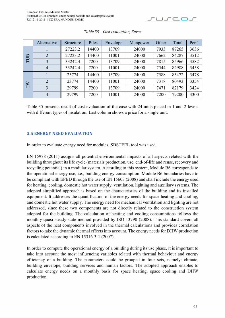
European Erasmus Mundus Master Sustainable Constructions under natural hazards and catastrophic events 520121-1-2011-1-CZ-ERA MUNDUS-EMMC
Table 35 – Cost evaluation, Euros
Alternative Structure Piles Envelope Manpower Other Total Per 1
TUB
1 27223.2 14400 13709 24000 7933 87265 3636 2 27223.2 14400 11001 24000 7662 84287 3512 3 33242.4 7200 13709 24000 7815 85966 3582 4 33242.4 7200 11001 24000 7544 82988 3458
TW
1 23774 14400 13709 24000 7588 83472 3478 2 23774 14400 11001 24000 7318 80493 3354 3 29799 7200 13709 24000 7471 82179 3424 4 29799 7200 11001 24000 7200 79200 3300
Table 35 presents result of cost evaluation of the case with 24 units placed in 1 and 2 levels with different types of insulation. Last column shows a price for a single unit.
3.5 ENERGY NEED EVALUATION In order to evaluate energy need for modules, SBSTEEL tool was used. EN 15978 (2011) assigns all potential environmental impacts of all aspects related with the building throughout its life cycle (materials production, use, end-of-life and reuse, recovery and recycling potential) in a modular system. According to this system, Module B6 corresponds to the operational energy use, i.e., building energy consumption. Module B6 boundaries have to be compliant with EPBD through the use of EN 15603 (2008) and shall include the energy used for heating, cooling, domestic hot water supply, ventilation, lighting and auxiliary systems. The adopted simplified approach is based on the characteristics of the building and its installed equipment. It addresses the quantification of the energy needs for space heating and cooling, and domestic hot water supply. The energy need for mechanical ventilation and lighting are not addressed, since these two components are not directly related to the construction system adopted for the building. The calculation of heating and cooling consumptions follows the monthly quasi-steady-state method provided by ISO 13790 (2008). This standard covers all aspects of the heat components involved in the thermal calculations and provides correlation factors to take the dynamic thermal effects into account. The energy needs for DHW production is calculated according to EN 15316-3-1 (2007). In order to compute the operational energy of a building during its use phase, it is important to take into account the most influencing variables related with thermal behaviour and energy efficiency of a building. The parameters could be grouped in four sets, namely: climate, building envelope, building services and human factors. The adopted approach enables to calculate energy needs on a monthly basis for space heating, space cooling and DHW production.
61

European Erasmus Mundus Master Sustainable Constructions under natural hazards and catastrophic events 520121-1-2011-1-CZ-ERA MUNDUS-EMMC
Figure 46 - Flowchart of the calculation of the energy consumption of the building [SBSTEEL,
Background and user guide, 2010]
Total energy need obtained for each of alternatives presented in Table 30. This values are showing energy need for heating, cooling and DHW for a square meter of a unit annually. Figure 47 displays general energy need breakdown for all alternatives.
Table 36 – Total energy need for alternatives Alternative kWh/m2/year 1 146.9 2 145.8 3 128.4 4 127.6
Figure 47 – Energy need breakdown
61%
32%
7%
Energy need breakdown
Heating
DHW
Cooling
62

European Erasmus Mundus Master Sustainable Constructions under natural hazards and catastrophic events 520121-1-2011-1-CZ-ERA MUNDUS-EMMC
3.6 SELECTION OF SOLUTIONS
Three criteria were considered for the final selection: x Economic – integrated costs;x Environment – environmental impact was considered by the level of GWPx Energy need per square meter.
8 options are assessed – 2 structural solutions (tubular and thin-walled members), 2 types of insulation (Rockwool and mineral wool) and 2 type of models (1 and 2 level models). Resume of considered criteria and corresponding values for each of alternative are shown in Table 37.
Table 37 – Resume of considered criteria
Alternative Economical €/module
Enviromental GWP, tCO2eq
Energy need, kWh/m2/year
TUB
1 3636 1 146.9 2 3512 1.24 145.8 3 3582 0.84 128.4 4 3458 1.08 127.6
TW
1 3478 1 146.9 2 3354 1.24 145.8 3 3424 0.84 128.4 4 3300 1.08 127.6
Selection by multi-axial representation method
The solution selection through multi-axial representation considers an axis for each individual indicator. The representation is possible for three indicators but the solution remains valid even for more indicators.
The first step of the method is the normalization of results: the solutions having the best performance in regard to a certain indicator is maximized to 100% while the rest of indicators are normalized to this value in percentages.
The second step is the computation of the distance to an ideal target, defined by the point of maximum coordinates (100,100,100). This can be easily done by computing the vector between the real coordinated points and the ideal target through the square root of sum of squares. Table 38 shows the normalized values and distances to target.
63

European Erasmus Mundus Master Sustainable Constructions under natural hazards and catastrophic events 520121-1-2011-1-CZ-ERA MUNDUS-EMMC
Table 38 - Selection through multi-axial representation
Al.
Economical Enviromental Energy need Distance to target
Colour on
graph €/module Norm. tCO2eq Norm. 𝑘𝑊ℎ𝑚2
𝑦𝑒𝑎𝑟Norm.
TUB
1 3636 90.76 1 84.00 146.9 86.86 22.67 2 3512 93.97 1.24 67.74 145.8 87.52 35.11 3 3582 92.13 0.84 100.00 128.4 99.38 7.90 4 3458 95.44 1.08 77.78 127.6 100 22.69
TW
1 3478 94.88 1 84.00 146.9 86.86 21.33 2 3354 98.39 1.24 67.74 145.8 87.52 34.63 3 3424 96.38 0.84 100.00 128.4 99.38 3.68 4 3300 100 1.08 77.78 127.6 100 22.22
Figure 48 – Multiaxial representation
The smallest distance to the target is obtained for the solution 3 in both tubular and thin-walled structural solutions of units, which by far is better than other systems.
Selection by characterization factor method
The method is based on using characterization factors in accordance to the importance of a specific indicator in the final decision choice. The factorized values multiply the normalized values which are finally added in a final score (aggregated value). The highest value represents the best score.
64

European Erasmus Mundus Master Sustainable Constructions under natural hazards and catastrophic events 520121-1-2011-1-CZ-ERA MUNDUS-EMMC The difficulty of the method is finding the right characterization factors reflecting the importance of indicators. Usually a block of experts can be consulted for finding adequate factor values. One solution is by considering factors in unitary ratios. Table 39 shows the factorized values and final scores using the following characterization factors for specific the three indicators considered:
ct = 0.40 for the energy need; cp = 0.30 for the economic assessment; ce = 0.25 for the environmental impact.
Table 39 - Selection by characterization factor method
Al.
Economical Enviromental Energy need Final score €/module Norm. Fact. tCO2eq Norm. Fact.
𝑘𝑊ℎ𝑚2
𝑦𝑒𝑎𝑟 Norm. Fact.
TUB
1 3636 90.76 27.23 1 84.00 25.20 146.9 86.86 34.74 87.17 2 3512 93.97 28.19 1.24 67.74 20.32 145.8 87.52 35.01 83.52 3 3582 92.13 27.64 0.84 100.00 30.00 128.4 99.38 39.75 97.39 4 3458 95.44 28.63 1.08 77.78 23.33 127.6 100 40.00 91.96
TW
1 3478 94.88 28.46 1 84.00 25.20 146.9 86.86 34.74 88.41 2 3354 98.39 29.52 1.24 67.74 20.32 145.8 87.52 35.01 84.85 3 3424 96.38 28.91 0.84 100.00 30.00 128.4 99.38 39.75 98.66 4 3300 100 30.00 1.08 77.78 23.33 127.6 100 40.00 93.33
X0.3 X0.3 X0.4 The highest final score is obtained for the solution 3 in thin-walled structural solution of units. It can be observed that the best solution is a model of 2 level made in thin-walled members with insulation of 120 mm made of Rockwool. As an alternative same solution made in tubular members can be proposed. Both selection methods showed that solution of 2 level model in both structural options with insulation made of Rockwool is the best. Even though it is not the cheapest option, it has the smallest environmental impact and has great energy performance, and so combination of this factors results in the best solution. This solution is followed by a 2 level model with mineral wool insulation. This solution has the best results in terms of price and energy need, however the environmental impact is significant which makes this solution less favourable.
65

European Erasmus Mundus Master Sustainable Constructions under natural hazards and catastrophic events 520121-1-2011-1-CZ-ERA MUNDUS-EMMC
CHAPTER 4 - CONCLUSIONS
Shelter is an option for the intermediate period in between the immediate aftermath and the finished reconstruction of buildings (or finding alternative permanent housing solution). Shelter is an essential component of survival in the early stages of a disaster. Recent disasters showed the unpreparedness of communities and urgent need of sheltering solutions.
The design of new solution of sheltering within this project is based on design of modular units which can be locally stored close to areas which might be affected. Units should be readily available for use and transportation when disaster strikes.
This work is confined to preliminary design of such units considering economic criteria, structural safety and environmental impact, which are the three pillars of sustainability.
Two structural solutions were considered – with tubular and thin-walled members. Models were designed in 1, 2 and 3 level options.
From structural point of view only one and two level models are efficient and are proposed for further research.
Material is not used efficiently in three level models, as the difference between 1 unit of 1 level model and 1 unit of 3 level model is more than 40%. Installation process for 3 level models will be more expensive due to the need of use of the heavy lifting equipment as cranes and need of work on height.
Models of 1 and 2 levels have a good structural performance and will not require such additional expenses for installation.
Units made of thin-walled profiles will require smaller amount of work in factory which can be performed by less skilful and experienced workers. Connections in thin-walled members are generally easier as no welding is needed. Proposed structural scheme of thin-walled units allows simpler installation of enveloping solutions as insulation can be introduced in between of structural studs, while tubular units will require arrangement of additional studs.
Taking into account sustainability assessment which included life cycle impact assessment, energy need and cost evaluation – it can be observed that models of 2 levels with insulation made of Rockwool have better overall performance than all other alternatives. Even though it is not the cheapest option, it has the smallest environmental impact and has great energy performance, and so combination of this factors results in the best solution.
This solution is followed by a 2 level model with mineral wool insulation. This solution has the best results in terms of price and energy need, however the environmental impact is significant which makes this solution less favourable.
66

European Erasmus Mundus Master Sustainable Constructions under natural hazards and catastrophic events 520121-1-2011-1-CZ-ERA MUNDUS-EMMC
CHAPTER 5 – REFERENCES
1. WHAT IF NYC..? Designing post-disaster housing for urban areas. Design case study, 2010.
2. LAWSON, R.M., GRUBB, P.J., PREWER, J., TREBILCOCK, P.J. Modular Construction using Light Steel Framing for Architects. The Steel Construction Institute, 1999
3. LAWSON, R.M., GRUBB, P.J., PREWER, J., TREBILCOCK, P.J. Modular Construction using Light Steel Framing for Engineers. The Steel Construction Institute, 1999
4. TUDORAN, O.A Integrated modular systems for emergency situations. PhD Thesis, UPT, 2014
5. GRECEA, D., TUDORAN, O.A. Using Modular Structures with Built-in Utilities for Temporary Shelters. Recent Advances in Civil and Mining Engineering, 2013
6. EM-ARCH Project Proposal 7. DUBINA, D., UNGUREANU, V., CIUTINA, A., TUCA, I., MUTIU, M. Sustainable
detached family house – case study. Journal of Steel Construction, 3, 2010, pp. 154-162 8. DUBINA, D., UNGUREANU, V., CIUTINA, A., MUTIU, M., GRECEA, D.
Innovative sustainable steel framing based affordable house solution for continental seismic areas. ICSA2010: Structures and Architecture, 2010
9. UNGUREANU, V., CIUTINA, A., TUCA, I., DUBINA, D., GRECEA, D., FULOP, L.A. Structural and Environmental Performance of Steel Framed Houses: A Case Study. Summary report of the Cooperative Activities. Cost Action C25. Volume 1: Integrated approach towards sustainable constructions, 2011, pp. 395-428
10. DUBINA, D., UNGUREANU, V., LANDOLFO, R. Design of cold-formed steel structures. Eurocode 3: Design of Steel structures. Part 1-3 Design of cold-formed steel structures. Ernst & Sohn, 2012
11. SANTOS, P., SIMOES DA SILVA, L., UNGUREANU, V. Energy efficiency of light-weight steel-framed buildings. ECCS, 2012
12. CIUTINA, A., TUCA, I., UNGUREANU, V., DUBINA, D. Design of buildings including environmental impact. Environmental Engineering and Management Journal, 9(8), 2010
13. TUCA, I., UNGUREANU, V., CIUTINA, A., DUBINA, D. Life-cycle assessment of a steel-framed family house. Journal Pollack Periodica, 2012
14. SAP2000. TUTORIAL MANUAL. Computers and Structures, Inc., 2006 15. GERVÁSIO, H., SANTOS, P., SIMOES DA SILVA, L., VASSART, O.,
HETTINGER, A., HUET, V. Large Valorisation on Sustainability of Steel Structures, background document. CMM Portugal, 2014
16. GERVÁSIO, H., SANTOS, P., SIMOES DA SILVA, L., VASSART, O., HETTINGER, A., HUET, V. Large Valorisation on Sustainability of Steel Structures, design guide. CMM Portugal, 2014
17. The Sphere Handbook, Humanitarian Charter and Minimum Standards in Humanitarian Response, The Sphere Project, 2011
18. National disaster housing Strategy. FEMA, 2009
67

European Erasmus Mundus Master Sustainable Constructions under natural hazards and catastrophic events 520121-1-2011-1-CZ-ERA MUNDUS-EMMC
19. SIMOES DA SILVA, L., GERVÁSIO, H., SIMOES, R. Design of steel structures. ECCS, 2013
20. VORNHOLZ, G. The sustainable development approach. Intereconomics, 1994 21. LAWSON, R. M. Building design using modules. New Steel Construction, 2007 22. LAWSON, R. M. Light steel modular construction. The Steel Construction Institute,
2001 23. Sustainable Construction: Designers, Check list. Constructing Excellence, 2004 24. FÎNTÎNĂ, T. Emergency shelters made from prefabricated modular containers. Thesis,
UPT, 2014 25. VELJKOVIC, M. Affordable House project presentation. LTU, 2010 26. SBSTEEL, Sustainability of Steel Buildings. Background and user guide. Research fund
for coal and steel of the European Community, 2010 27. The Sphere Project, http://www.sphereproject.org/ 28. The International Federation of Red Cross and Red Crescent Societies,
http://www.ifrc.org/ 29. QuickBase Foundations, http://www.quickbaseuk.co.uk/ 30. TechnoMetal Post, http://www.technometalpostnj.com/ 31. Sustainable Development Commission, http://www.sd-commission.org.uk/ 32. Residential Shipping Container, http://www.residentialshippingcontainerprimer.com/ 33. Modular Building Institute, http://www.modular.org/ 34. Steel construction Info, http://www.steelconstruction.info/ 35. Tiny House Blog, http://tinyhouseblog.com/ 36. EM-DAT, International Disaster Database, http://www.emdat.be/ 37. Serbia floods. Report. Belgrade, 2014 38. Wikipedia, https://en.wikipedia.org/wiki/2014_Southeast_Europe_floods 39. Köppen-Geiger climate classification [http://koeppen-geiger.vu-wien.ac.at/] 40. EN 1990:2002, Eurocode – Basis of structural design. CEN, 2002 41. EN 1991-1-1:2002, Eurocode 1: Actions on structures - Part 1-1: General actions –
Densities, self-weight, imposed loads for buildings. CEN, 2002 42. EN 1991-1-3:2003, Eurocode 1: Actions on structures - Part 1-3: General actions –
Snow loads. CEN, 2003 43. EN 1991-1-4:2005, Eurocode 1: Actions on structures - Part 1-4: General actions –
Wind actions. CEN, 2005 44. P100-1-2013, Seismic design code – Part I – Design rules for building, 2013 45. EN 1993-1-1:2005, Eurocode 3: Design of steel structures - Part 1-1: General rules and
rules for buildings. CEN, 2005 46. EN 1993-1-3:2006, Eurocode 3: Design of steel structures - Part 1-3: General rules
Supplementary rules for cold-formed members and sheeting. CEN, 2006 47. EN 1993-1-3:2005, Eurocode 3: Design of steel structures - Part 1-8: Design of joints.
CEN, 2005 48. ISO 14040:2006, Environmental management - Life cycle assessment - Principles and
framework. ISO, 2006 49. ISO 14044:2006, Environmental management - Life cycle assessment - Requirements
and guidelines. ISO, 2006
68

European Erasmus Mundus Master Sustainable Constructions under natural hazards and catastrophic events 520121-1-2011-1-CZ-ERA MUNDUS-EMMC
50. BS EN 15804:2012 Sustainability of construction works. Environmental product declarations. Core rules for the product category of construction products. BSI, 2012
51. BS EN 15978:2011 Sustainability of construction works. Assessment of environmental performance of buildings. Calculation method. BSI, 2011
52. ISO 13790:2008 Energy performance of buildings — Calculation of energy use for space heating and cooling. ISO, 2008
53. BS EN 15316-3-1:2007 Heating systems in buildings. Method for calculation of system energy requirements and system efficiencies. Domestic hot water systems, characterisation of needs (tapping requirements). BSI, 2007
69

Input dataClimatic Zone: CfbCity: BucharestStage Analysis: Conceptual stage
Alternative 1
Building: Single & multi-family building
Characteristics of the building:
L: 6 (m) B: 2.5 (m)
Af: 15 (m2)
Height: 2.8 (m)
Floors: 1
Scope of Analysis: Cradle-to-grave + end-of-life recycling (Module A to D)Lifespan of Analysis: 50 Years
Indoor Conditions
Heating set point: 20 ºCCooling set point: 25 ºCAir Flow rate, heating: 0.6 ac/hAir Flow rate, cooling: 0 ac/h
Building Systems
Heating: Electric resistance (Efficience: 1.00)Cooling: Split (Efficience: 3.00)Renewable electricity prodution: 0 kWh/YearDHW System: Electric Boiler (Efficience: 0.9)Renewable energy - for DHW use: 0 kWh/YearVentilation type: Natural
Additional envelope information
Shading device: Interior opaque curtains LightColor of opaque envelope: LightGround floor type: Slab-on ground floorSoil type: Clay or Silt
European Erasmus Mundus Master Sustainable Constructions under natural hazards and catastrophic events 520121-1-2011-1-CZ-ERA MUNDUS-EMMC
ANNEX 1 - SBSTEEL REPORT
70

European Erasmus Mundus Master Sustainable Constructions under natural hazards and catastrophic events 520121-1-2011-1-CZ-ERA MUNDUS-EMMC
Macro-Component:Roof Floor:
Layer 1
Layer 2
Layer 3U-Value: 0.58 W/m2.KInertia: 13 435 J/m2.K
Layer 1 materials
Bitumen waterproofing membrane : 5 (mm)Concrete screed : 5 (mm)Vapour barrier : 0.5 (mm)
Layer 2 materials
OSB : 18 (mm)Air : 0 (mm)Rock wool : 120 (mm)Cold rolled steel : 14 (kg/m2)Gypsum Plasterboard : 15 (mm)
Layer 3 materials
Paint : 0.125 (mm)
Environment Impacts (per m2):Prodution Stage
(A1:A3)Construction Stage
(A4:A5)Use Stage(B1:B7)
End-of-Life Stage(C1:C4)
Recycling Stage(D)
GWP (kg CO2 eq) 2.89E+1 6.47E-1 1.08E+0 2.80E+0 -3.40E+1
ODP (kg CFC 11 eq) 1.58E-6 1.05E-7 3.26E-7 1.89E-7 0.00E+0
AP (Kg SO2 eq) 2.12E-1 3.55E-3 6.46E-3 1.82E-1 -6.25E-2
EP (kg (PO4)-3) 2.31E-2 7.70E-4 6.15E-4 5.80E-3 -4.15E-3
POPC (kg Ethene eq) 2.36E-2 1.24E-4 3.92E-4 7.60E-3 -1.59E-2
ADP-E (kg Sb eq) 4.12E-1 4.67E-3 2.28E-2 8.41E-3 -1.83E-1
ADP-F (MJ) 7.27E+2 1.02E+1 4.92E+1 1.87E+1 -2.37E+2
71
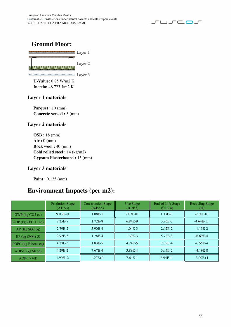
European Erasmus Mundus Master Sustainable Constructions under natural hazards and catastrophic events 520121-1-2011-1-CZ-ERA MUNDUS-EMMC
Layer 1
Layer 2
Layer 3U-Value: 0.85 W/m2.KInertia: 48 723 J/m2.K
Layer 1 materials
Parquet : 10 (mm)Concrete screed : 5 (mm)
Layer 2 materials
OSB : 18 (mm)Air : 0 (mm)Rock wool : 40 (mm)Cold rolled steel : 14 (kg/m2)Gypsum Plasterboard : 15 (mm)
Layer 3 materials
Paint : 0.125 (mm)
Environment Impacts (per m2):
Prodution Stage(A1:A3)
Construction Stage(A4:A5)
Use Stage(B1:B7)
End-of-Life Stage(C1:C4)
Recycling Stage(D)
GWP (kg CO2 eq)
ODP (kg CFC 11 eq)
AP (Kg SO2 eq)
EP (kg (PO4)-3)
POPC (kg Ethene eq)
ADP-E (kg Sb eq)
ADP-F (MJ)
Ground Floor:
9.03E+0 1.08E-1 7.07E+0 1.33E+1 -2.30E+0
7.25E-7 1.72E-8 6.84E-9 3.96E-7 -4.64E-11
2.79E-2 5.90E-4 1.04E-3 2.02E-2 -1.13E-2
2.92E-3 1.28E-4 1.39E-3 5.72E-3 -6.69E-4
4.23E-3 1.83E-5 4.24E-5 7.09E-4 -6.55E-4
4.29E-2 7.67E-4 3.89E-4 3.05E-2 -4.19E-8
1.90E+2 1.70E+0 7.64E-1 6.94E+1 -3.00E+1
72

1-CZ-ERA MUNDUS-EMMC
European Erasmus Mundus Master Sustainable Constructions under natural hazards and catastrophic events 520121-1-2011-
Exterial Wall:
Layer 1 Layer 2 Layer 3U-Value: 0.31 W/m2.KInertia: 13 391 J/m2.K
Layer 1 materials
Paint : 0.125 (mm)Rendering (reinforced) : 1.16 (mm)EPS : 40 (mm)
Layer 2 materials
OSB : 13 (mm)Air : 0 (mm)Rock wool : 120 (mm)Cold rolled steel : 15 (kg/m2)Gypsum Plasterboard : 15 (mm)
Layer 3 materials
Paint : 0.125 (mm)
Environment Impacts (per m2):
Prodution Stage(A1:A3)
Construction Stage(A4:A5)
Use Stage(B1:B7)
End-of-Life Stage(C1:C4)
Recycling Stage(D)
GWP (kg CO2 eq) 3.84E+1 5.24E-1 1.66E+0 2.87E+0 -3.64E+1
ODP (kg CFC 11 eq) 1.27E-6 8.49E-8 1.15E-7 1.56E-7 0.00E+0
AP (Kg SO2 eq) 2.13E-1 2.88E-3 5.44E-3 1.81E-1 -6.69E-2
EP (kg (PO4)-3) 2.26E-2 6.23E-4 9.57E-4 1.05E-2 -4.45E-3
POPC (kg Ethene eq) 2.80E-2 1.01E-4 2.49E-4 7.58E-3 -1.71E-2
ADP-E (kg Sb eq) 4.17E-1 3.78E-3 1.10E-2 6.91E-3 -1.96E-1
ADP-F (MJ) 7.30E+2 8.29E+0 2.18E+1 1.51E+1 -2.54E+2
73
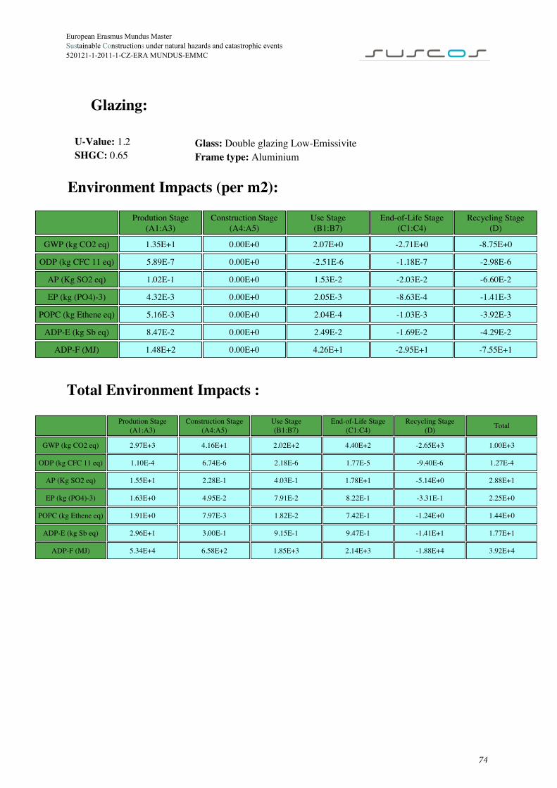
European Erasmus Mundus Master Sustainable Constructions under natural hazards and catastrophic events 520121-1-2011-1-CZ-ERA MUNDUS-EMMC
Glazing:
U-Value: 1.2SHGC: 0.65
Glass: Double glazing Low-EmissiviteFrame type: Aluminium
Environment Impacts (per m2):
Prodution Stage(A1:A3)
Construction Stage(A4:A5)
Use Stage(B1:B7)
End-of-Life Stage(C1:C4)
Recycling Stage(D)
GWP (kg CO2 eq) 1.35E+1 0.00E+0 2.07E+0 -2.71E+0 -8.75E+0
ODP (kg CFC 11 eq) 5.89E-7 0.00E+0 -2.51E-6 -1.18E-7 -2.98E-6
AP (Kg SO2 eq) 1.02E-1 0.00E+0 1.53E-2 -2.03E-2 -6.60E-2
EP (kg (PO4)-3) 4.32E-3 0.00E+0 2.05E-3 -8.63E-4 -1.41E-3
POPC (kg Ethene eq) 5.16E-3 0.00E+0 2.04E-4 -1.03E-3 -3.92E-3
ADP-E (kg Sb eq) 8.47E-2 0.00E+0 2.49E-2 -1.69E-2 -4.29E-2
ADP-F (MJ) 1.48E+2 0.00E+0 4.26E+1 -2.95E+1 -7.55E+1
Total Environment Impacts :
Prodution Stage(A1:A3)
Construction Stage(A4:A5)
Use Stage(B1:B7)
End-of-Life Stage(C1:C4)
Recycling Stage(D) Total
GWP (kg CO2 eq) 2.97E+3 4.16E+1 2.02E+2 4.40E+2 -2.65E+3 1.00E+3
ODP (kg CFC 11 eq) 1.10E-4 6.74E-6 2.18E-6 1.77E-5 -9.40E-6 1.27E-4
AP (Kg SO2 eq) 1.55E+1 2.28E-1 4.03E-1 1.78E+1 -5.14E+0 2.88E+1
EP (kg (PO4)-3) 1.63E+0 4.95E-2 7.91E-2 8.22E-1 -3.31E-1 2.25E+0
POPC (kg Ethene eq) 1.91E+0 7.97E-3 1.82E-2 7.42E-1 -1.24E+0 1.44E+0
ADP-E (kg Sb eq) 2.96E+1 3.00E-1 9.15E-1 9.47E-1 -1.41E+1 1.77E+1
ADP-F (MJ) 5.34E+4 6.58E+2 1.85E+3 2.14E+3 -1.88E+4 3.92E+4
74

European Erasmus Mundus Master Sustainable Constructions under natural hazards and catastrophic events 520121-1-2011-1-CZ-ERA MUNDUS-EMMC
Energy assessmentEnergy need for space Heating
Heat Transfer by Transmission
Qtr,Walls Qtr,Glazing Qtr,Ground Qtr,Roof Qtr,Total
kWh/Year kWh/Year kWh/Year kWh/Year kWh/Year
1172.84 318.49 511.98 734.95 2730.68
Heat Transfer by Ventilation
Qve
kWh/Year
707.75
Heat transfer breakdown
Heat Gains
Glazing Opaque Internal
Qsol,Glasing Qsol,Opaque QInt
kWh/Year kWh/Year kWh/Year
952.66 -5.15 906.66
Jan Feb Mar Apr May Jun Jul Aug Sep Oct Nov Dec
Qsol,Glazed(kWh) 26.71 47.44 77.81 94.11 120.59 128.31 135.81 119.47 86.25 58.63 31.67 25.86
Qsol,Opaque(kWh) -13.72 -5.88 -1.34 3.43 9.06 10.98 12.11 9.31 2.37 -5.03 -12.05 -14.38
75

European Erasmus Mundus Master Sustainable Constructions under natural hazards and catastrophic events 520121-1-2011-1-CZ-ERA MUNDUS-EMMC
Solar Gains - Glazed
Solar Gains - Opaque
Energy need for Heating
Qh,nd Jan Feb Mar Apr May Jun Jul Aug Sep Oct Nov Dec
kWh 370.62 210.41 83.72 35.77 3.32 0 0 0 0 34.09 159.41 313.39
kWh/m2 24.71 14.03 5.58 2.38 0.22 0 0 0 0 2.27 10.63 20.89
Energy Breakdown
Building totals for Heating
Energy need Delivered Energy Renewable Energy Primary energy
kWh/Year kWh/m2/Year kWh/Year kWh/m2/Year kWh/Year kWh/m2/Year kgoe/Year kgoe/m2/Year
1210.73 80.72 1210.73 80.72 0 0 339 22.6
76

European Erasmus Mundus Master Sustainable Constructions under natural hazards and catastrophic events 520121-1-2011-1-CZ-ERA MUNDUS-EMMC
Energy need for space Cooling
Heat Transfer by Transmission
Qtr,Walls Qtr,Glazing Qtr,Ground Qtr,Roof Qtr,Total
kWh/Year kWh/Year kWh/Year kWh/Year kWh/Year
1732.35 470.42 777.28 1085.56 4065.61
Heat Transfer by Ventilation
Qve
kWh/Year
0
Heating transfer breakdown
Heat Gains
Glazing Opaque Internal
Qsol,Glasing Qsol,Opaque QInt
kWh/Year kWh/Year kWh/Year
862.02 -5.15 906.66
Jan Feb Mar Apr May Jun Jul Aug Sep Oct Nov Dec
Qsol,Glazed(kWh) 26.71 46.88 70.19 86.57 108.52 112.59 116.27 102.78 78.39 55.6 31.67 25.86
Qsol,Opaque(kWh) -13.72 -5.88 -1.34 3.43 9.06 10.98 12.11 9.31 2.37 -5.03 -12.05 -14.38
77

European Erasmus Mundus Master Sustainable Constructions under natural hazards and catastrophic events 520121-1-2011-1-CZ-ERA MUNDUS-EMMC
Solar Gains - Glazed
Solar Gains - Opaque
Energy need for Cooling
Qh,nd Jan Feb Mar Apr May Jun Jul Aug Sep Oct Nov Dec
kWh 0 0 0 0 39.59 93.72 141.69 117.58 27.44 0 0 0
kWh/m2 0 0 0 0 2.64 6.25 9.45 7.84 1.83 0 0 0
Energy Breakdown
Building totals for Cooling
Energy need Delivered Energy Renewable Energy Primary energy
kWh/Year kWh/m2/Year kWh/Year kWh/m2/Year kWh/Year kWh/m2/Year kWh/Year kWh/m2/Year
420.01 28 140 9.33 0 0 39.2 2.61
78

European Erasmus Mundus Master Sustainable Constructions under natural hazards and catastrophic events 520121-1-2011-1-CZ-ERA MUNDUS-EMMC
Building totals for DHW Prodution
Energy need Delivered Energy Renewable Energy Primary energy
kWh/Year kWh/m2/Year kWh/Year kWh/m2/Year kWh/Year kWh/m2/Year kgoe/Year kgoe/m2/Year
572.87 38.19 636.52 42.43 0 0 178.23 11.88
Total Energy NeedBuilding total per month
Jan Feb Mar Apr May Jun Jul Aug Sep Oct Nov Dec
Qh+c,nd(kWh) 370.62 210.41 83.72 35.77 42.91 93.72 141.69 117.58 27.44 34.09 159.41 313.39
Qt,nd(kWh) 419.27 254.36 132.37 82.86 91.56 140.8 190.34 166.23 74.52 82.74 206.49 362.04
Qdhw,nd(kWh) 48.65 43.95 48.65 47.09 48.65 47.09 48.65 48.65 47.09 48.65 47.09 48.65
Building totals per year
Energy need Delivered Energy Renewable Energy Primary energy
kWh/Year kWh/m2/Year kWh/Year kWh/m2/Year kWh/Year kWh/m2/Year kgoe/Year kgoe/m2/Year
2203.6 146.91 1987.25 132.48 0 0 556.43 37.1
Energy Need Breakdown Delivered Energy Breakdown
Building totals per year (life span)
Energy need Delivered Energy Renewable Energy Primary energy
kWh kWh/m2 kWh kWh/m2 kWh kWh/m2 kgoe kgoe/m2
110180.22 7345.35 99362.51 6624.17 0 0 27821.5 1854.77
79