modular ontology modeling
TRANSCRIPT

Semantic Web 0 (2021) 1–0 1IOS Press
1 1
2 2
3 3
4 4
5 5
6 6
7 7
8 8
9 9
10 10
11 11
12 12
13 13
14 14
15 15
16 16
17 17
18 18
19 19
20 20
21 21
22 22
23 23
24 24
25 25
26 26
27 27
28 28
29 29
30 30
31 31
32 32
33 33
34 34
35 35
36 36
37 37
38 38
39 39
40 40
41 41
42 42
43 43
44 44
45 45
46 46
47 47
48 48
49 49
50 50
51 51
Modular Ontology ModelingCogan Shimizu a Karl Hammar b Pascal Hitzler a
a Department of Computer Science, Kansas State University, USAb Department of Computing, Jönköping University, Sweden
Abstract. Reusing ontologies for new purposes, or adapting them to new use-cases, is frequently difficult. In our experiences,we have found this to be the case for several reasons: (i) differing representational granularity in ontologies and in use-cases, (ii)lacking conceptual clarity in potentially reusable ontologies, (iii) lack and difficulty of adherence to good modeling principles,and (iv) a lack of reuse emphasis and process support available in ontology engineering tooling. In order to address theseconcerns, we have developed the Modular Ontology Modeling (MOMo) methodology, and its supporting tooling infrastructure,CoModIDE (the Comprehensive Modular Ontology IDE – “commodity”). MOMo builds on the established eXtreme Designmethodology, and like it emphasizes modular development and design pattern reuse; but crucially adds the extensive use ofgraphical schema diagrams, and tooling that support them, as vehicles for knowledge elicitation from experts. In this paper, wepresent the MOMo workflow in detail, and describe several useful resources for executing it. In particular, we provide a thoroughand rigorous evaluation of CoModIDE in its role of supporting the MOMo methodology’s graphical modeling paradigm. We findthat CoModIDE significantly improves approachability of such a paradigm, and that it displays a high usability.
Keywords: keywords
1. Introduction
Over the last two decades, ontologies have seen wide-spread use for a variety of purposes. Some of them,such as the Gene Ontology [1], have found significantuse by third parties. However, the majority of ontolo-gies have seen hardly any re-use outside the use casesfor which they were originally designed [2, 3].
It behooves us to ask why this is the case, in partic-ular, since the heavy re-use of ontologies was part ofthe original conception for the Semantic Web field. In-deed, many use cases have high topic overlap, so thata re-use of ontologies on similar topics should, in prin-ciple, lower development cost. However, according toour experience, it is often much easier to develop anew ontology from scratch, than it is to try to re-useand adapt an existing ontology. We can observe thatthis sentiment is likely shared by many others, as thenew development of an ontology so often seems to bepreferred over adapting an existing one.
We posit, based on our experience, that four of themajor issues preventing wide-spread re-use are (i) dif-
fering representational granularity, (ii) lack of concep-tual clarity in many ontologies, (iii) lack and difficultyof adherence to established good modeling principles,and (iv) lack of re-use emphasis and process supportin available ontology engineering tooling. We explainthese aspects in more detail in the following. As a rem-edy for these issues, we propose tool-supported modu-larization, in a specific sense which we also explain indetail.
Representational granularity refers to modeling choiceswhich determine the level of detail to be included inthe ontology, and thus in the data (knowledge) graph.As an example, one model may simply refer to temper-atures at specific space-time locations. Another modelmay also record an uncertainty interval. A third modelmay also record information about the measurementinstrument, while a fourth may furthermore record cal-ibration data for said instrument. Another examplemay be population figures for cities; the values are fre-quently estimated through the use of statistical mod-els. That is, depending on the data and which statisticalmodel was used, different figures would be calculated.
1570-0844/21/$35.00 © 2021 – IOS Press and the authors. All rights reserved

2 C. Shimizu, K. Hammar, P. Hitzler /
1 1
2 2
3 3
4 4
5 5
6 6
7 7
8 8
9 9
10 10
11 11
12 12
13 13
14 14
15 15
16 16
17 17
18 18
19 19
20 20
21 21
22 22
23 23
24 24
25 25
26 26
27 27
28 28
29 29
30 30
31 31
32 32
33 33
34 34
35 35
36 36
37 37
38 38
39 39
40 40
41 41
42 42
43 43
44 44
45 45
46 46
47 47
48 48
49 49
50 50
51 51
Note that a fine-grained ontology can be populatedwith coarse-granularity data; the converse is not true.If a use case requires fine-granularity data, a coarse-grained ontology is essentially useless. On the otherhand, using a fine-grained ontology for a use case thatrequires only coarse granularity data is unwieldy dueto (possibly massively) increased size of ontology anddata graph.
Even more problematically, is that two use cases maydiffer in granularity in different ways in different partsof the data, respectively, ontology. That is, the level ofabstraction is not uniform across the data. For exam-ple, one use case may call for details on the statisticalmodels underlying population data, but not for mea-surement instruments for temperatures, whereas an-other use case may only need estimated population fig-ures, but require calibration data for temperature mea-surements. Essentially, this means that attempting tore-use a traditional ontology may require modifying itin very different ways in different parts of the ontol-ogy. An additional complication is that ontologies aretraditionally presented as monolithic entities and it isoften hard to determine where exactly to apply such achange in granularity.
Conceptual clarity is a rather elusive concept that cer-tainly has a strong subjective component. By this, wemean that an ontology should be designed and pre-sented in such a way that it “makes sense” to do-main experts, without too much difficulty. While pre-sentation and documentation do play a major role, it isequally important to have intuitive naming conventionsfor ontological entities and, in particular, a structuralorganization (i.e., a schema for a data graph) which ismeaningful for the domain expert.
We can briefly illustrate this using an example from theOAEI1 Conference benchmark ontologies [4, 5]. Onelists “author of paper” and “author of student paper”as two distinct subclasses of “person.” This raises thequestion: why is “author of student paper” not a sub-class of “author of paper” (apart from subclassing bothas “person” which we will discuss in the next para-graph). In another ontology in this collection, “author”is a subclass of “user", and “author” itself has exactlytwo subclasses: “author, who is not a reviewer” and“co-author” – which is hardly intuitive.
1For more information on the Ontology Alignment EvaluationInitiative, see http://oaei.ontologymatching.org/.
By definition, an ontology with high conceptual clar-ity will be much easier to re-use, simply because itis much easier to understand the ontology in the firstplace. Thus, a key quest for ontology research is to de-velop ontology modeling methodologies which makeit easier to produce ontologies with high conceptualclarity.
That following already established good modelingprinciples makes an ontology easier to understand andre-use, should go without saying. However, good mod-eling principles are not simply a checklist that can eas-ily be followed. Even simple cases, such as the recom-mendation to not have perdurants and endurants2 to-gether in subclass relationships (in the example above,author should not be a subclass of person; rather, au-thorship is a role of the person) are commonly not fol-lowed in existing ontologies. At the current stage of re-search, “good modeling” appears to largely be a func-tion of modeling experience and more of an art, thana science, which has not been condensed well enoughinto tangible insights that can easily be written up in atutorial or textbook.
A further issue is that even in cases where the afore-mentioned re-use challenges are manageable, imple-menting and subsequently maintaining re-use in prac-tice is problematic due to limited support for re-use inavailable tooling. Once a reusable ontology resourcehas been located, a suitable reuse method must first beselected; e.g., cloning the entire design into the targetontology/namespace, using owl:imports to include theentire source ontology as-is, cloning individual defi-nitions, locally subsuming or aligning to remote on-tology entities, etc. The authors have previously con-tributed methodological guidance supporting develop-ers in selecting an appropriate reuse method based onthe modeling context [6, 177–184]; but without com-prehensive tooling support, carrying out such reusein practice (especially when several resources are re-used) is still time-consuming and error-prone.
Furthermore, through ontology re-use, the ontologistcommits to a design and logic built by a third party.As the resulting ontology evolves, keeping track ofthe provenance of re-used ontological resources andtheir locally instantiated representations may become
2These are ontological terms; a perdurant means “an entity thatonly exists partially at any given point in time” and and endurantmeans “an entity that can be observed as a complete concept, regard-less of the point time.”

C. Shimizu, K. Hammar, P. Hitzler / 3
1 1
2 2
3 3
4 4
5 5
6 6
7 7
8 8
9 9
10 10
11 11
12 12
13 13
14 14
15 15
16 16
17 17
18 18
19 19
20 20
21 21
22 22
23 23
24 24
25 25
26 26
27 27
28 28
29 29
30 30
31 31
32 32
33 33
34 34
35 35
36 36
37 37
38 38
39 39
40 40
41 41
42 42
43 43
44 44
45 45
46 46
47 47
48 48
49 49
50 50
51 51
important, e.g., to resolve design conflicts resultingfrom differing requirements, or to keep up-to-date withthe evolution of the re-used ontology. This is partic-ularly important in case remote resources are reuseddirectly rather than through cloning into a local rep-resentation (e.g., using owl:imports or through align-ments to remote entities using subclass or equivalencerelations); in those cases remote changes could, un-beknownst to the developer, cause their ontology tobecome inconsistent. Such state-keeping is decidedlynon-trivial without appropriate tool support.
Processes and tools should be sought that make it pos-sible to leverage modeling experience by seasoned ex-perts, without actually requiring their direct involve-ment. This was one of the original ideas behind ontol-ogy re-use which, unfortunately, did not quite work outthat well, for reasons including those mentioned above.Our modularization approach, however, together withthe systematic utilization of ontology design patterns,and our accompanying tools, gives us a means to ad-dress this issue.
The notion of module has taken on a variety of mean-ings in the Semantic Web community [7–9]. For ourpurposes, a module is a part of the ontology (i.e., a sub-set of the ontology axioms) which captures a key no-tion together with its key attributes. For example, anevent module may contain, other than an Event class,also relations and classes designed for the representa-tion of the event’s place, time, and participants. On theother hand, a simple module for a cooking process mayencompass relations and classes for recording ingredi-ents and their amounts, time and equipment required,and so on. A module is thus as much a technical entity,in the sense of a defined part of an ontology, as wellas a conceptual entity, in the sense that it should en-compass different classes (and relationships betweenthem) which “naturally” (from the perspective of do-main experts) belong together. Modules may overlap.They may be nested. They provide an organization ofan ontology as an interconnected collection of mod-ules, each of which resonates with the correspondingpart of domain conceptualization by the experts.
Note that modules, in this sense, indicate a depar-ture from a more traditional perspective on ontologies,where they are often viewed as enhanced taxonomies,with a strong emphasis on the structure of the classsubsumption hierarchy. Modules can contain their owntaxonomy structure, guided by the design logic of themodule, that ideally integrates into usability-wise co-
herent taxonomy of the ontology as a whole; but thelatter is not a hard requirement. From our perspective,the occurrence of subclass relationships within an on-tology is not a key guiding principle for modeling orontology organization. As we will see, modules makeit possible to approach ontology modeling in a divide-and-conquer fashion; first, by modeling one module ata time, and then connecting them.3
Modules furthermore provide an easy way of avoid-ing the hassle of dealing with ontologies that are largeand monolithic: understanding an ontology amountsto understanding each of its modules, and then theirinterconnections. This, at the same time, provides arecipe for documentation which resonates with domainexperts’ conceptualizations (which were captured bymeans of the modules), and thus makes the documen-tation and ontology easier to understand. Additionally,using modules facilitates modification, and thus adapt-ing an ontology to a new purpose, as a module is muchmore easily replaced by a new module with, for in-stance, higher granularity, because the module inher-ently identifies where changes should be localized.
The systematic use of ontology design patterns [12,13] is another central aspect of our approach, as manyof their promises resonate with the issues that our ap-proach is addressing [14]. An ontology design patternis a generic solution to a recurring ontology modelingproblem. To give an example, a “Trajectory” patternwould be a partial ontology that can be used to record“trajectories,” such as the route of a ship or piece ofcargo. If well-designed, this pattern may, with only mi-nor and easy modifications, be suitable to be used asa template for trajectory modules within many ontolo-gies. It must be noted that patterns are not one-size-fits-all solutions. For example, the Trajectory pattern from[15], which we have found to be highly versatile, as-sumes a discretized recording of a trajectory (as a time-sequence of locations), however it would not accountfor recording of a trajectory as, say, a set of equations.
In our approach, well-designed ontology design pat-terns, provided as templates to the ontology model-ers, make it easier to follow already established goodmodeling principles, as the patterns themselves will al-ready reflect them [16]. When a module is to be mod-eled, within our process there will always be a check
3Other divide and conquer approaches have also recently beenproposed [10, 11], and while they seem to be compatible with ours,exact relationships still need to be established.

4 C. Shimizu, K. Hammar, P. Hitzler /
1 1
2 2
3 3
4 4
5 5
6 6
7 7
8 8
9 9
10 10
11 11
12 12
13 13
14 14
15 15
16 16
17 17
18 18
19 19
20 20
21 21
22 22
23 23
24 24
25 25
26 26
27 27
28 28
29 29
30 30
31 31
32 32
33 33
34 34
35 35
36 36
37 37
38 38
39 39
40 40
41 41
42 42
43 43
44 44
45 45
46 46
47 47
48 48
49 49
50 50
51 51
whether some already existing ontology design patternis suitable to be adapted for the purpose. Modules, assuch, are often derived from patterns as templates.
The principles and key aspects laid out above are tiedtogether in a clearly defined modular ontology mod-eling process which is laid out below, and which isa refinement – with some changes of emphasis – ofthe eXtreme Design methodology [17]. It is further-more supported by a set of tools developed for sup-port of this process, the CoModIDE plug-in to Protégé,and which we will discuss in detail below. Also cen-tral to our approach is that it is usually a collabora-tive process with a (small) team that jointly has the re-quired domain, data and ontology engineering exper-tise, and that the actual modeling work utilizes schemadiagrams as the central artifact for modeling, discus-sion, and documentation.
This paper is structured as follows. Section 2 describesour related work – this covers precursor methods, theeXtreme Design methodology, and overviews of con-cepts fundamental to our approach. Section 3 describesour modular ontology modeling process in detail. Sec-tion 4 presents CoModIDE as a tool for supporting thedevelopment of modular ontologies through a graph-ical modeling paradigm, as well as a rigorous evalu-ation of its effectiveness and usability. Section 5 de-scribes additional, supporting infrastructure for thisprocess. Then, in Section ??, we provide experientialdata on executing this process. Finally, in Section 6,we conclude.
This paper significantly extends [18] and summarizesseveral other workshop and conference papers: [19],[20], and [21].
2. Related Work
2.1. Ontology Engineering Methods
The ideas underpinning the Modular Ontology Model-ing methodology build on years of prior ontology engi-neering research, covering organizational, process, andtechnological concerns that impact the quality of anontology development process and its results.
The METHONTOLOGY methodology is presentedby Férnandez et al. in [22]. It is one of the earlierattempts to develop a development method specifi-cally for ontology engineering processes (prior meth-ods often include ontology engineering as a sub-
discipline within knowledge management, conflatingthe ontology-specific issues with other more generaltypes of issues). Férnandez et al. suggest, based largelyon the authors’ own experiences of ontology engineer-ing, an ontology lifecycle consisting of six sequen-tial work phases or stages: Specification, Conceptu-alisation, Formalisation, Integration, Implementation,and Maintenance. Supporting these stages are a set ofsupport activities: Planification, Acquiring knowledge,Documenting, and Evaluating.
The On-To-Knowledge Methodology (OTKM) [23] is,similarly to METHONTOLOGY, a methodology forontology engineering that covers the big steps, butleaves out the detailed specifics. OTKM is framed ascovering both ontology engineering and a larger per-spective on knowledge management and knowledgeprocesses, but it heavily emphasises the ontology de-velopment activities and tasks (in [23] denoted theKnowledge Meta Process). OTKM emphasises initialcollaboration between domain experts and ontologyengineers in the Kick-off phase. In the subsequent Re-finement phase an ontology engineer formalises theinitial semi-formal model into a real ontology on theirown, without aid of a domain expert. In subsequentEvaluation, both technical and user-focused aspects ofthe knowledge based system in which the ontology isused, are evaluated. Finally, the Application and Evo-lution phase concerns the deployment of said knowl-edge based system, and the organisational challengesassociated with maintenance responsibilities.
DILIGENT, by Pinto et al. [24], is an abbreviation forDistributed, Loosely-Controlled and Evolving Engi-neering of Ontologies, and is a method aimed at guid-ing ontology engineering processes in a distributedSemantic Web setting. The method emphasises de-centralised work processes and ontology usage, do-main expert involvement, and ontology evolution man-agement. This distributed development process is for-malised into five activities: build, local adaptation,analysis, revision, and local update. The authors showhow Rhetorical Structure Theory [25] can be used asa framework to constrain design discussions in a dis-tributed ontology engineering setting, guiding the de-sign process.
In all three of these well-established methods, the pro-cess steps that are defined are rather coarse-grained.They give guidance on overall activities that need to beperformed in constructing an ontology, but more fine-grained guidance (e.g., how to solve common model-

C. Shimizu, K. Hammar, P. Hitzler / 5
1 1
2 2
3 3
4 4
5 5
6 6
7 7
8 8
9 9
10 10
11 11
12 12
13 13
14 14
15 15
16 16
17 17
18 18
19 19
20 20
21 21
22 22
23 23
24 24
25 25
26 26
27 27
28 28
29 29
30 30
31 31
32 32
33 33
34 34
35 35
36 36
37 37
38 38
39 39
40 40
41 41
42 42
43 43
44 44
45 45
46 46
47 47
48 48
49 49
50 50
51 51
ing problems, how to represent particular designs onconcept or axiom level, or how to work around limi-tations in the representation language) is not included.It is instead assumed that the reader is familiar withsuch specifics of constructing an ontology. This lack ofguidance arguably is a contributor to the three issuespreventing re-use, discussed in Section 1.
2.2. Ontology Design Patterns
Ontology Design Patterns (ODPs) were introduced ataround the same time independently by Gangemi [13]and Blomqvist and Sandkuhl [12], as potential solu-tions to the drawbacks of classic methods describedabove. The former defines such patterns by way ofthe characteristics that they display, including exam-ples such as “[an ODP] is a template to represent,and possibly solve, a modelling problem” [13, p. 267]and “[an ODP] can/should be used to describe a‘best practice’ of modelling” [13, p. 268]. The latterdescribes ODPs as generic descriptions of recurringconstructs in ontologies, which can be used to con-struct components or modules of an ontology. Both ap-proaches emphasise that patterns, in order to be eas-ily reusable, need to include not only textual descrip-tions of the modelling issue or best practice, but alsosome formal ontology language encoding of the pro-posed solution. The documentation portion of the pat-tern should be structured and contain those fields orslots that are required for finding and using the pattern.
A substantial body of work has been developed basedon this idea, by a sizable distributed research com-munity4. Key contributions include the eXtreme De-sign methodology (detailed in Section 2.3) and sev-eral other pattern-based ontology engineering methods(Section 2.4). The majority of work on ODPs has beenbased on the use of miniature OWL ontologies as theformal pattern encoding, but there are several exam-ples of other encodings, the most prominent of whichare OPPL [26] and more recently OTTR [11].
MOMo extends on those methods, but also incorpo-rates results from our past work on how to documentODPs [27–29], how to implement ODP support tool-ing [30] and how to instantiate patterns into modulesby “stamping out copies” [16].
4https://ontologydesignpatterns.org
Fig. 1. eXtreme Design method overview, from [17].
2.3. eXtreme Design
The eXtreme Design (XD) methodology [17] wasoriginally proposed as a reaction to previous waterfall-oriented methods (e.g., some of those discussed above).XD instead borrows from agile software engineeringmethods, emphasizing a divide-and-conquer approachto problem-solving, early or continuous deploymentrather than a “one-shot” process, and early and fre-quent refactoring as the ontology grows. Crucially, XDis built on reusing of ontological best practices viaODPs.
The XD method consists of a number of tasks, as illus-trated in Figure 1. The first two tasks deal with estab-lishing a project context (i.e., introducing initial termi-nology and obtaining an overview of the problem) andcollecting initial requirements in the form of a priori-tized list of user stories (describing the required func-tionality in layman’s terms). These steps are performedby the whole XD team together with the customer, whois familiar with the domain and who understands therequired functionalities of the resulting ontology. Thelater steps of the process are performed in pairs of twodevelopers (these steps are in the figure enclosed in thelarge box). They begin by selecting the top prioritiseduser story that has not yet been handled, and transformthat story into a set of requirements in the form of com-petency questions (data queries), contextual statements(invariants), and reasoning requirements. Customer in-volvement at this stage is required to ensure that theuser story has been properly understood and that theelicited requirements are correctly understood.
The development pair then selects one or a small set ofinterdependent competency questions for modelling.They attempt to match these against a known ODP,possibly from a designated ODP library. The ODP is

6 C. Shimizu, K. Hammar, P. Hitzler /
1 1
2 2
3 3
4 4
5 5
6 6
7 7
8 8
9 9
10 10
11 11
12 12
13 13
14 14
15 15
16 16
17 17
18 18
19 19
20 20
21 21
22 22
23 23
24 24
25 25
26 26
27 27
28 28
29 29
30 30
31 31
32 32
33 33
34 34
35 35
36 36
37 37
38 38
39 39
40 40
41 41
42 42
43 43
44 44
45 45
46 46
47 47
48 48
49 49
50 50
51 51
adapted and integrated into the ontology module un-der development (or, if this iteration covers the firstrequirements associated with a given user story, anew module is created from it). The module is testedagainst the selected requirements to ensure that it cov-ers them properly. If that is the case, then the nextset of requirements from the same user story is se-lected, a pattern is found, adapted, and integrated, andso on. Once all requirements associated with one userstory have been handled, the module is released bythe pair and integrated with the ontology developed bythe other pairs in the development team. The integra-tion may be performed either by the development pairthemselves, or by a specifically designated integrationpair.
XD has been evaluated experimentally and observa-tionally, with results indicating that the method con-tributes to reduced error rates in ontologies [31, 32],increased coverage of project requirements [31], andthat pattern usage is perceived as useful and helpful byinexperienced users [31–33]. However, results also in-dicate that there are pitfalls associated with a possibil-ity of over-dependence on ODP designs, as noted in[33].
2.4. Other Pattern-based Methods
SAMOD [34], or Simplified Agile Methodology forOntology Development, is a recently developed method-ology that builds on and borrows from test-drivenand agile methods (in particular eXtreme Design).SAMOD emphasises the use of tests to confirm that thedeveloped ontology is consistent with requirements,and prescribes that the developer construct three typesof such tests: model tests, data tests, and query tests.The method prescribes a light-weight three-step pro-cess broadly mirroring XD, i.e., consisting of (1) con-structing an ontology module as a partial solution tothe development scenario (including tests), (2) merg-ing that new module into the main branch ontology,(3) refactoring as needed. After each of these steps, allthe tests defined for the module and/or main branchontology are executed, and development is halted untilall tests are passed.
Hammar [6] presents a set of proposed improvementsto the XD methodology under the umbrella label “XD1.1”. These include (1) a set of roles and role-specificresponsibilities in an XD project, (2) suggestions onhow to select and implement other forms of ontologyre-use in XD than just patterns (e.g., import, remote
Fig. 2. Factors affecting conceptual modeling, from [35].
references, slicing, partial cloning), and (3) a projectadaptation questionnaire supporting XD projects inadapting the process to their particular developmentcontext (e.g., team cohesion, distribution, skill level,domain knowledge, etc).
XD, SAMOD, and XD 1.1 emphasize the needs forsuitable support tooling for, e.g., finding suitableODPs, instantiating those ODPs into an ontology, andexecuting tests across the ontology or parts of it. Indeveloping MOMo and the CoModIDE platform, wepropose and develop solutions to two additional sup-port tooling needs: that of intuitive and accessiblegraphical modeling, and that of a curated high-qualitypattern library.
2.5. Graphical Conceptual Modelling
[35] proposes three factors (see Figure 2) that influencethe construction of a conceptual model, such as an on-tology; namely, the person doing the modeling (boththeir experience and know-how, and their interpreta-tion of the world, of the modeling task, and of modelquality in general), the modeling grammar (primar-ily its expressive power/completeness and its clarity),and the modeling process (including both initial con-ceptualisation and subsequent formal model-making).Crucially, only the latter two factors can feasibly becontrolled in academic studies. Research in this spacetends to focus on one or the other of these factors, i.e.,studying the characteristics of a modeling language ora modeling process. Our work on CoModIDE straddlesthis divide: employing graphical modeling techniquesreduces the grammar available from standard OWL tothose fragments of OWL that can be represented intu-itively in graphical format; employing design patternsaffects the modeling process.
Graphical conceptual modeling approaches have beenextensively explored and evaluated in fields such asdatabase modeling, software engineering, businessprocess modeling, etc. Studying model grammar, [36]compares EER notation with an early UML-like no-

C. Shimizu, K. Hammar, P. Hitzler / 7
1 1
2 2
3 3
4 4
5 5
6 6
7 7
8 8
9 9
10 10
11 11
12 12
13 13
14 14
15 15
16 16
17 17
18 18
19 19
20 20
21 21
22 22
23 23
24 24
25 25
26 26
27 27
28 28
29 29
30 30
31 31
32 32
33 33
34 34
35 35
36 36
37 37
38 38
39 39
40 40
41 41
42 42
43 43
44 44
45 45
46 46
47 47
48 48
49 49
50 50
51 51
tation from a comprehensibility point-of-view. Thiswork observes that restrictions are easier to understandin a notation where they are displayed coupled to thetypes they apply to, rather than the relations they rangeover. [37] proposes a quality model for EER diagramsthat can also extend to UML. Some of the quality crite-ria in this model, that are relevant in graphical model-ing of OWL ontologies, include minimality (i.e., avoid-ing duplication of elements), expressiveness (i.e., dis-playing all of the required elements), and simplicity(displaying no more than the required elements).
[38] studies the usability of UML, and reports thatusers perceive UML class diagrams (closest in in-tended use to ontology visualizations) to be less easy-to-use than other types of UML diagrams; in partic-ular, relationship multiplicities (i.e., cardinalities) areconsidered frustrating by several subjects. UML dis-plays such multiplicities by numeric notation on theend of connecting lines between classes. [39] analysesUML and argues that while it is a useful tool in a de-sign phase, it is overly complex and as a consequence,suffers from redundancies, overlaps, and breaks in uni-formity. [39] also cautions against using difficult-to-read and -interpret adornments on graphical models, asUML allows.
Various approaches have been developed for present-ing ontologies visually and enabling their develop-ment through a graphical modeling interface, the mostprominent of which is probably VOWL, the Visual No-tation for OWL Ontologies [40], and its implementa-tion viewer/editor WebVOWL [41, 42]. VOWL em-ploys a force-directed graph layout (reducing the num-ber of crossing lines, increasing legibility) and explic-itly focuses on usability for users less familiar withontologies. As a consequence of this, VOWL ren-ders certain structures in a way that, while not for-mally consistent with the underlying semantics, sup-ports comprehensibility; for instance, datatype nodesand owl:Thing nodes are duplicated across the can-vas, so that the model does not implode into a tightcluster around such often used nodes. It has beenevaluated over several user studies with users rang-ing from laymen to more experienced ontologists, withresults indicating good comprehensibility. CoModIDEhas taken influence from VOWL, e.g., in how we ren-der datatype nodes. However, in a collaborative edit-ing environment in which the graphical layout of nodesand edges needs to remain consistent for all users, andrelatively stable over time, we find the force-directed
graph structure (which changes continuously as enti-ties are added/removed) to be unsuitable.
For such collaborative modeling use cases, the com-mercial offering Grafo5 offers a very attractive fea-ture set, combining the usability of a VOWL-like nota-tion with stable positioning, and collaborative editingfeatures. Crucially, however, Grafo does not supportpattern-based modular modeling or import statements,and only supports RDFS semantics, and as a web-hosted service, does not allow for customizations orplugins that would support such a modeling paradigm.
CoModIDE is partially based on the Protégé pluginOWLAx, as presented in [43]. OWLAx plugin supportsone-way translation from graphical schema diagramsdrawn by the user, into OWL ontology classes andproperties; however, it does not render such constructsback into a graphical form. There is thus no way ofcontinually maintaining and developing an ontologyusing only OWLAx. There is also no support for de-sign pattern re-use in this tool.
3. The Modular Ontology Modeling Methodology
Modular Ontology Modeling (MOMo6) consists of awell-defined process, together with the utilization ofspecific components that support the process. The de-sign characteristics of MOMo and CoModIDE providethe following benefits over the prior options introducedin Sections 2.3 and 2.4:
Module focus – While earlier approaches may rec-ommend the instantiation of ODPs into the targetontology, they typically do not emphasize the self-containedness of those instantiations; instead, ODPsare often merged into larger blocks of functional-ity or entirely monolithic ontologies. In MOMo, bycontrast, instantiating and interlinking small self-contained modules is a defining characteristic, thatprovides several benefits; e.g., maintainability is sim-plified since each module can be modified with mini-mal impact on the ontology as a whole; and the prove-nance of each part of the ontology, back to the origi-nal requirements, can easily be maintained in moduledocumentation or metadata.
5https://gra.fo6Momo is the protagonist in the 1973 fantasy novel “Momo” by
Michael Ende. The antagonists are Men in Grey that cause people towaste time.

8 C. Shimizu, K. Hammar, P. Hitzler /
1 1
2 2
3 3
4 4
5 5
6 6
7 7
8 8
9 9
10 10
11 11
12 12
13 13
14 14
15 15
16 16
17 17
18 18
19 19
20 20
21 21
22 22
23 23
24 24
25 25
26 26
27 27
28 28
29 29
30 30
31 31
32 32
33 33
34 34
35 35
36 36
37 37
38 38
39 39
40 40
41 41
42 42
43 43
44 44
45 45
46 46
47 47
48 48
49 49
50 50
51 51
A curated ODP library – Methodologies based onODP usage tend to assume the existence of suit-able patterns. While the ODP community continuesto develop and publish patterns through, e.g., theontologydesignpatterns.org portal, those patterns varyin terms of documentation quality and completeness,foundational semantics, granularity, specificity or ab-straction, etc. In practice, this makes consistent ODPusage in non-trivially sized projects difficult. MOMoinstead suggests the use of an internally consistentlibrary of patterns (see Section 3.4); either a well-curated public library with general coverage, or onedeveloped specifically for the project/domain at hand.
Diagram-first modeling – Where other methodologiesmight recommend the use of illustrations as a way ofexplicating ODP design, and suggest the use of post-facto ontology documentation for communication andother purposes, in MOMo the developed schema di-agrams and their accompanying human-readable doc-umentation are themselves first-order deliverables ofthe ontology engineering process; their (manual) trans-lation into OWL is a final step of post-processing.The use of such more accessible formalisms enablesnon-ontology-experts to easily participate in develop-ment of and quality assurance over the developed mod-ules and ontologies; not only as requirements sourcesand passive observers, but as active participants. Fur-thermore, since the diagrams and their documenta-tion are ontology language-agnostic, they can be trans-lated into other formalisms than OWL, should the needarise, by a developer with no or limited OWL exper-tise.
In this part of the paper, we lay out the key compo-nents, namely schema diagrams, our approach to OWLaxiomatization, ontology design patterns, and the con-cept of modules already mentioned previously, as wellas the process which ties them together. In section 4and 5, we discuss our supporting tools and infrastruc-ture, however they should be considered just one pos-sible instantiation of the more general MOMo method-ology. Indeed, most of the first part of the MOMoprocess is, in our experience, best done in analogmode, armed with whiteboards, flip-charts and a suit-able modeling team.
3.1. The Modeling Team
Team composition is of critical importance for estab-lishing a versatile modular ontology. Different per-spectives are very helpful, as long as the group does
not lose focus. Arrival at a consensus model betweenall parties which constitutes a synthesis of differentperspectives is key, and such a consensus is much morelikely to be suitable to accommodate future use casesand modifications. It is therefore advisable to havemore than one domain expert with overlapping exper-tise, and more than one ontology engineer on the team.Based on our experiences, three types of participantsare needed in order to have a team that can establisha modular ontology: domain experts, ontology engi-neers, and data scientists. Of course some people maybe able to fill more than one role. An overall team sizeof 6-12 people appears to be ideal, based on our experi-ences (noted in Section 5.5). Meetings with the wholeteam will be required, but in the MOMo process mostof the work will fall on the ontology engineers betweenthe meetings.
1. The domain experts should primarily bring a deepknowledge of the relevant subject area(s) and ofthe use case scenario(s). Ideally, they should alsobe aware of perspectives taken by other domainexperts in order to avoid overspecialization of themodel.
2. The ontology engineers should be familiar withthe MOMo process, supporting tools, and rele-vant standards (in particular, OWL), and guidethe meetings. Their role is to capture the discus-sions, resulting in (draft) schema diagrams whichare then further discussed and refined by the team.Between team meetings, they will also work outdetailed documentation of what has been dis-cussed, which, in turn, will be used as promptsin following modeling sessions. At least one ofthe ontology engineers should have a deep under-standing of the logical underpinnings of OWL.
3. The data scientists should bring a detailed under-standing of the actual data that is relevant to theuse case(s) and will or may be utilized (e.g., in-tegrated by means of the ontology as overarchingschema). Their role is to make sure that the modeldoes not deviate in an incompatible way from theactual data that is available.
3.2. Schema Diagrams
Schema diagrams are a primary tool of the MOMo pro-cess. In particular, they are the visual vehicle used tocoalesce team discussions into a draft model and usedcentrally in the documentation. This diagram-basedapproach is also reflected in our tools, which we willpresent in sections 4–5.

C. Shimizu, K. Hammar, P. Hitzler / 9
1 1
2 2
3 3
4 4
5 5
6 6
7 7
8 8
9 9
10 10
11 11
12 12
13 13
14 14
15 15
16 16
17 17
18 18
19 19
20 20
21 21
22 22
23 23
24 24
25 25
26 26
27 27
28 28
29 29
30 30
31 31
32 32
33 33
34 34
35 35
36 36
37 37
38 38
39 39
40 40
41 41
42 42
43 43
44 44
45 45
46 46
47 47
48 48
49 49
50 50
51 51
Fig. 3. Schema diagram for the Provenance module from the En-slaved Ontology [44]. It is based on the Provenance pattern from[20], which in turn is based on the core of PROV-O [45].
Let us first explain what we do – and do not – meanby schema diagram, and we use Figure 3 as an exam-ple,7 which depicts the Provenance module from theEnslaved Ontology [44].
Our schema diagrams are labeled graphs that in-dicate OWL entities and their (possible) relation-ships. Nodes can be labeled by (1) classes (Entity-WithProvenance – rectangular, orange, solid border),(2) modules (Agent, PersonRecord, ProvenanceAc-tivity – rectangular, light blue, dashed border), (3)controlled vocabularies (DocumentTypes, LicenseIn-formation – rectangular, purple, solid border), (4)datatypes (xsd:string, xsd:anyURI – oval, yellow, solidborder). Arrows can be white-headed without label,indicating a subclass relationship (the arrow betweenPersonRecord and EntityWithProvenance) or can belabeled with the name of the property, which could bea data or an object property, which is identified by thetarget of the arrow, which may be a datatype.
Indication of a module in a diagram means that in-stead of the node (the light blue, dashed border), theremay be a complex model in its very own right, whichwould be discussed, depicted, and documented sepa-rately. For example, PersonRecord in the Enslaved On-tology is a complex module with several sub-modules.The diagram in Figure 3 “collapses” this into a singlenode, in order to emphasize what is essential for theProvenance module. Controlled vocabularies are pre-defined sets of IRIs with a specific meaning that is doc-umented externally (i.e., not captured in the ontology
7The schema diagrams in this paper were produced with yEd,available from https://www.yworks.com/products/yed/.
itself). A typical example would be IRIs for physicalunits like meter or gram or, as in our example dia-gram, IRIs for specific copyright licences, such as CC-BY-SA. Datatypes would be the concrete datatypes al-lowed in OWL. This type of schema diagram underliesa study on automatic schema diagram creation fromOWL files [19].
Note that our schema diagrams do not directly indicatewhat the underlying OWL axioms are. A (labeled) ar-row only indicates that a property could typically beused between nodes of the indicated types. It does notindicate any of functionality, existential or universalrestriction, etc. It also does not indicate any specificdomain or range axioms or use of logical connectives,such as conjunction or disjunction. In the end, the on-tology will consist of a set of OWL axioms (i.e., a con-crete axiomatization will be done), but these are cre-ated rather late in the process. During team modeling,simple diagrams help to focus on the essentials andare intuitively accessible even for participants with nobackground in ontology engineering. The ontology en-gineers, however, should keep in mind that logical ax-ioms are needed eventually and that the diagrams aloneremain highly ambiguous.
3.3. OWL Axioms
As already mentioned, OWL axioms are the key con-stituents of an ontology as a data artifact, although inour experience quality documentation is of at least thesame importance. As has been laid out elsewhere [46],axiomatizations can have different interpretations, andwhile they can, for example, be used for performingdeductive reasoning, this is not their main role as partof the MOMo approach. Rather, for our purposes ax-ioms serve to disambiguate meaning, for a human userof the ontology. As such, they can also be understoodas a way to disambiguate the schema diagram, as ap-propriate (e.g., by labeling a property functional, bydeclaring domain and range restrictions).
As such, we recommend a rather complete axiomati-zation, as long as it does not force an overly specificreading on the ontology. We usually use the checklistfrom the OWLAx tool [43] to axiomatize with simpleaxioms. More complex axioms, in particular those thatspan more than two nodes in a diagram, can be addedconventionally or by means of the ROWLTab Protégéplug-in [47, 48]. We also utilize what we call structuraltautologies which are axioms that are in fact tautolo-gies such as A v >0R.B, to indicate that individuals in

10 C. Shimizu, K. Hammar, P. Hitzler /
1 1
2 2
3 3
4 4
5 5
6 6
7 7
8 8
9 9
10 10
11 11
12 12
13 13
14 14
15 15
16 16
17 17
18 18
19 19
20 20
21 21
22 22
23 23
24 24
25 25
26 26
27 27
28 28
29 29
30 30
31 31
32 32
33 33
34 34
35 35
36 36
37 37
38 38
39 39
40 40
41 41
42 42
43 43
44 44
45 45
46 46
47 47
48 48
49 49
50 50
51 51
Fig. 4. Schema diagram of the MODL Provenance ODP. It is basedon the core of PROV-O [45]
classes A and B may have an R relation between them,and that this would be a typical usage of the propertyR.8
3.4. Ontology Design Patterns
As already mentioned, Ontology Design Patterns (ODPs)have originated in the early 2000s as reusable solu-tions to frequently occurring ontology design prob-lems. Most ODPs can currently be found on theontologydesignpatterns.org portal, and they appear tobe of very varied quality both in terms of their designand documentation, and following a variety of differ-ent design principles. While they proved to be use-ful for the community [14], as part of MOMo, we re-imagine ontology design patterns and their use.
Most importantly, rather than working with a crowd-sourced collection of ODPs, there seems to be a sig-nificant advantage in working with a well-curated li-brary of ontology design patterns that are developedwith a similar mindset, and expressed and documentedin a uniform way. A first version of such a library isthe Modular Ontology Design Library (MODL) [20],which contains patterns that we have frequently foundto be useful in the recent past. We furthermore utilizethe Ontology Pattern Language (OPLa) [28, 29] whichis an annotation language using OWL that makes itpossible to work with ODPs (and modules) in a pro-grammatic way.
As an example, a schema diagram for the MODLProvenance pattern is provided in Figure 4. In MOMo,
8This is similar to the schema:domainIncludes andschema:rangeIncludes from Schema.org. We note, however, that astructural tautology is slightly stricter, in that it directly pairs twoconcepts via the role, whereas Schema.org’s is a many-to-manyapproach.
the pattern would be used as a template in the sensethat it serves as a blueprint, usually for a module –such as the Provenance module depicted in Figure 3in the resulting ontology. That is, the pattern can bemodified, simplified, extended at will, but usually boththe schema diagram and the axioms of the ODP willstill be reflected and in some way recognizable in themodule. The resulting ontology will also use OPLa tocapture the information that the resulting module hasre-used an ODP as a template.
3.5. Modules
An (ontology) module is a part of an ontology whichcaptures a key notion, and its key relations to other no-tions. An example that was already discussed is givenin Figure 3. A module may sometimes consist of a cen-tral class together with relations (properties) to otherclasses, modules, controlled vocabularies or datatypes,but can sometimes also be of a more complex struc-ture.
Modules can be overlapping, or nested. While they areoften based on some shared semantics, as encoded inan ODP, this is not a hard requirement; the purpose ofthe module is to encapsulate a set of interrelated func-tionality, the logic of which classes and properties thatthe module covers can be, and often is, guided, notonly by the semantics of the domain, but also by thedevelopment context and use case. For example, in thecontext of Figure 3, the PersonRecord class could rea-sonably be considered to be outside the module. Like-wise, the EntityWithProvenance class may or may notbe considered part of the PersonRecord module. Thelatter may depend on the question how “central” prove-nance for person records is, in the application contextof the ontology. In this sense, ontology modules areambiguous in their delineation, just as the human con-cepts they are based on.
As a data artifact, though, i.e., in the OWL file of theontology, we will use the above-mentioned OntologyPattern Language OPLa to identify modules, i.e. theontology engineers will have to make an assessmenthow to delineate each module in this case. OPLa willfurthermore be used to identify ODPs (if any) whichwere used as templates for a module.
Finally, an ontology’s modules will drive the documen-tation, which will usually discuss each module in turn,with separate schema diagrams, axioms, examples andexplanations, and will only at the very end discuss the

C. Shimizu, K. Hammar, P. Hitzler / 11
1 1
2 2
3 3
4 4
5 5
6 6
7 7
8 8
9 9
10 10
11 11
12 12
13 13
14 14
15 15
16 16
17 17
18 18
19 19
20 20
21 21
22 22
23 23
24 24
25 25
26 26
27 27
28 28
29 29
30 30
31 31
32 32
33 33
34 34
35 35
36 36
37 37
38 38
39 39
40 40
41 41
42 42
43 43
44 44
45 45
46 46
47 47
48 48
49 49
50 50
51 51
Fig. 5. Schema diagram of a supply chain ontology currently under development by the authors.
overall ontology which is essentially a composition ofthe modules. In a diagram that encompasses severalmodules, the modules can be identified visually usingframes or boxes around sets of nodes and arrows. Anexample for this is given in figure 5. Several modulesare identified by grey boxes in this diagram, includingnested modules such as on the lower right.
3.6. The MOMo Workflow
We now describe the Modular Ontology Modelingworkflow that we have been applying and refining overthe past few years. It borrows significantly from theeXtreme Design approach described in Section 2.3, buthas an emphasis on modularization, systematic use ofschema diagrams, and late-stage OWL generation. Ta-ble 1 summarizes the steps of the workflow, and thefollowing sections discuss each step in more detail. Awalk-through tutorial for the approach can be found in[49].
This workflow is not necessarily a strict sequence, andwork on later steps may cause reverting to an earlier
step for modifications. Sometimes subsequent stepsare done together, e.g., 4 and 5, or 7 and 8.
Steps 1 through 4 can usually be done through a fewshorter one-hour teleconferences (or meetings), thenumber of which depends a lot on the group dynam-ics and prior experience of the participants. This se-quence would usually also include a brief tutorial onthe modeling process. If some of the participants al-ready have a rather clear conception of the use casesand data sources, then 2 or 3 one-hour calls would of-ten suffice.
In our experience, synchronous engagement (in thesense of longer meetings) of the modeling team usuallycannot be avoided for step 5. Ideally, they would beconducted through in-person meetings, which for effi-ciency should usually be set up for 2 to 3 subsequentdays. Online meetings can also be almost as effective,but for this we recommend several, at least 3, subse-quent half-day sessions about 4-5 hours in length.
Steps 6 to 10 are mostly up to the ontology engineersat the team, however they would request feedback and

12 C. Shimizu, K. Hammar, P. Hitzler /
1 1
2 2
3 3
4 4
5 5
6 6
7 7
8 8
9 9
10 10
11 11
12 12
13 13
14 14
15 15
16 16
17 17
18 18
19 19
20 20
21 21
22 22
23 23
24 24
25 25
26 26
27 27
28 28
29 29
30 30
31 31
32 32
33 33
34 34
35 35
36 36
37 37
38 38
39 39
40 40
41 41
42 42
43 43
44 44
45 45
46 46
47 47
48 48
49 49
50 50
51 51
Table 1MOMo Workflow
Step Responsible Output
1. Describe use cases & data sources Entire team Use case descriptions2. Gather competency questions Entire team List of CQs3. Identify key notions Entire team List of key notions4. Identify existing ODPs Ontology engineers Selected ODP(s) for each key notion.5. Create module diagrams Entire team Diagrammatic representation of the solution module.6. Document modules & axioms Ontology engineers &
domain expertsModule documentation with embedded schema diagrams, axioma-tization, etc. (e.g., in LaTeX, Word, HTML format).
7. Create ontology diagram Ontology engineers Diagrammatic representation of the whole composed ontology.8. Add spanning axioms Ontology engineers Documentation of the entire ontology with embedded schema dia-
grams, axiomatization, etc. (e.g., in LaTeX, Word, HTML format).9. Review naming & axioms Ontology engineers Updated module and ontology documentation.10. Create OWL file & axioms Ontology engineers An OWL file for publication and use.
correctness checks from the data and domain experts.This can be done asynchronously, but depending onpreference could also include some brief teleconfer-ences (or meetings).
3.6.1. Describe use cases and gather possible datasources
As the first step, the use case, i.e., the problem to beaddressed, should be described. The output descriptioncan be very brief, e.g., a paragraph of text, and it doesnot necessarily have to be very crisp. In fact it may de-scribe a set of related use cases rather than one specificuse case, and it may include future extensions whichare currently out of scope. Setting up a use case de-scription in this way alerts the modeling team to thefact that the goal is to arrive at a modular ontologythat is extensible and re-useable for adjacent but dif-ferent purposes. In addition to capturing the problemitself, the use case descriptions can also describe exist-ing data sources that the ontology needs to be able torepresent or align against, if any.
An example for such a use case description can befound in Figure 6. In this particular case, the possibledata sources would be a set of different recipe websitessuch as allrecipes.com.
3.6.2. Gather competency questionsCompetency questions are examples for queries of in-terest, expressed in natural language, that should be an-swerable from the data graph with which the ontologywould be populated. Competency questions help to re-fine the use case scenario, and can also aid as a san-ity check on the adequacy of the data sources for theuse case. While the competency questions can often begathered during work on the use case description, it is
Design an ontology that can be used as part ofa “recipe discovery” website. The ontology shallbe set up such that content from existing recipewebsites can be mapped into it (i.e. the ontol-ogy will be populated with data from the recipewebsites). On the discovery website, detailedgraph-queries (using the ontology) shall producelinks to recipes from different recipe websites asresults. The ontology should be extendable to-wards incorporation of additional external data,e.g., nutritional information about ingredients ordetailed information about cooking equipment.
Fig. 6. Example use case description, taken from [49].
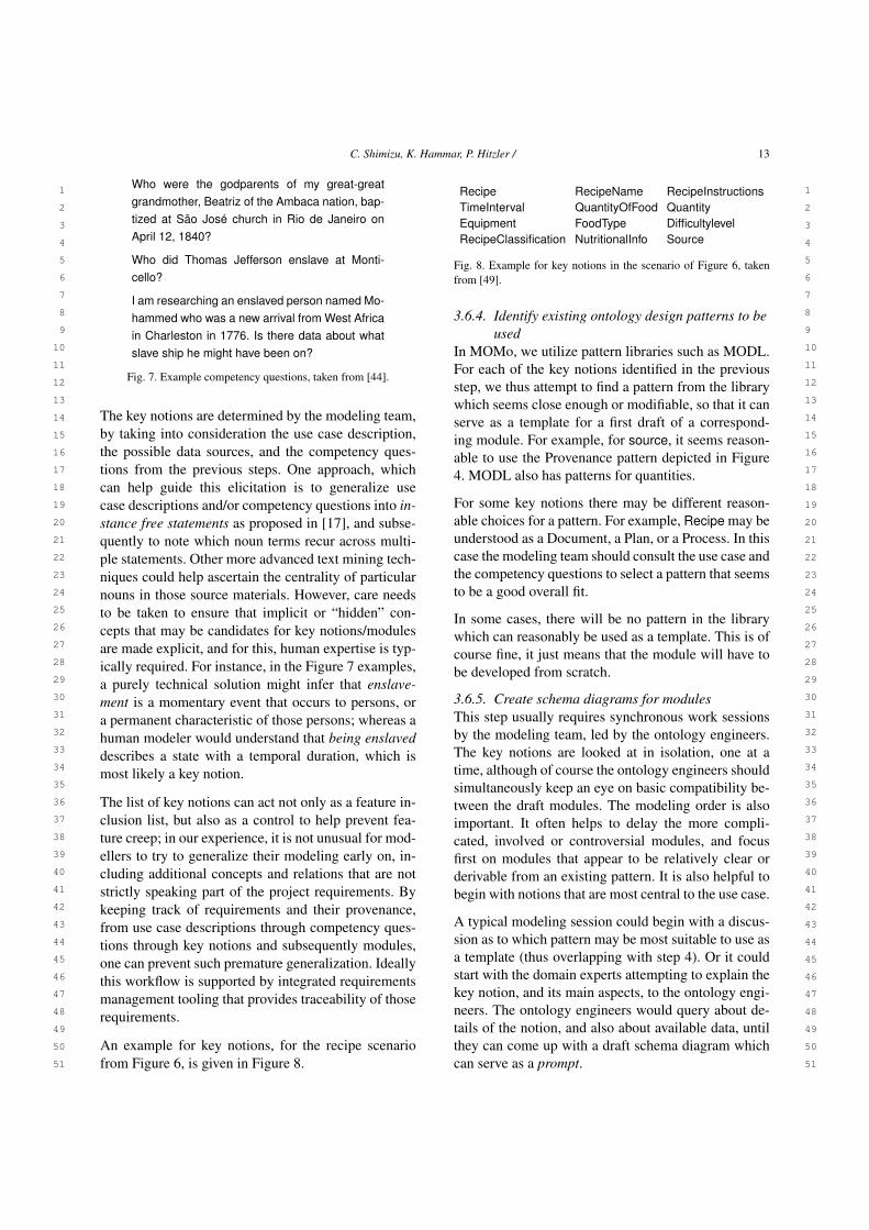
sometimes also helpful to collect them from potentialfuture users. For example, for an ontology on the his-tory of the slave trade [44], professionals, school chil-dren, and some members of the general public wereasked to provide competency questions. A few exam-ples are provided in Figure 7. We found experientially,10-12 sufficiently different competency questions willbe enough.
3.6.3. Identify key notions for the domain to bemodeled
This is a central step which sets the stage for the ac-tual modeling work in step 5. The main idea is thateach of the identified key notions will become a mod-ule, however, during modeling, some closely relatednotions may also become combined into a single mod-ule. It is also possible that at a later stage is realizedthat a key notion had been forgotten, which is easilycorrected by adding the new key notion to the previouslist.
C. Shimizu, K. Hammar, P. Hitzler / 13
1 1
2 2
3 3
4 4
5 5
6 6
7 7
8 8
9 9
10 10
11 11
12 12
13 13
14 14
15 15
16 16
17 17
18 18
19 19
20 20
21 21
22 22
23 23
24 24
25 25
26 26
27 27
28 28
29 29
30 30
31 31
32 32
33 33
34 34
35 35
36 36
37 37
38 38
39 39
40 40
41 41
42 42
43 43
44 44
45 45
46 46
47 47
48 48
49 49
50 50
51 51
Who were the godparents of my great-greatgrandmother, Beatriz of the Ambaca nation, bap-tized at São José church in Rio de Janeiro onApril 12, 1840?
Who did Thomas Jefferson enslave at Monti-cello?
I am researching an enslaved person named Mo-hammed who was a new arrival from West Africain Charleston in 1776. Is there data about whatslave ship he might have been on?
Fig. 7. Example competency questions, taken from [44].
The key notions are determined by the modeling team,by taking into consideration the use case description,the possible data sources, and the competency ques-tions from the previous steps. One approach, whichcan help guide this elicitation is to generalize usecase descriptions and/or competency questions into in-stance free statements as proposed in [17], and subse-quently to note which noun terms recur across multi-ple statements. Other more advanced text mining tech-niques could help ascertain the centrality of particularnouns in those source materials. However, care needsto be taken to ensure that implicit or “hidden” con-cepts that may be candidates for key notions/modulesare made explicit, and for this, human expertise is typ-ically required. For instance, in the Figure 7 examples,a purely technical solution might infer that enslave-ment is a momentary event that occurs to persons, ora permanent characteristic of those persons; whereas ahuman modeler would understand that being enslaveddescribes a state with a temporal duration, which ismost likely a key notion.
The list of key notions can act not only as a feature in-clusion list, but also as a control to help prevent fea-ture creep; in our experience, it is not unusual for mod-ellers to try to generalize their modeling early on, in-cluding additional concepts and relations that are notstrictly speaking part of the project requirements. Bykeeping track of requirements and their provenance,from use case descriptions through competency ques-tions through key notions and subsequently modules,one can prevent such premature generalization. Ideallythis workflow is supported by integrated requirementsmanagement tooling that provides traceability of thoserequirements.
An example for key notions, for the recipe scenariofrom Figure 6, is given in Figure 8.
Recipe RecipeName RecipeInstructionsTimeInterval QuantityOfFood QuantityEquipment FoodType DifficultylevelRecipeClassification NutritionalInfo Source
Fig. 8. Example for key notions in the scenario of Figure 6, takenfrom [49].
3.6.4. Identify existing ontology design patterns to beused
In MOMo, we utilize pattern libraries such as MODL.For each of the key notions identified in the previousstep, we thus attempt to find a pattern from the librarywhich seems close enough or modifiable, so that it canserve as a template for a first draft of a correspond-ing module. For example, for source, it seems reason-able to use the Provenance pattern depicted in Figure4. MODL also has patterns for quantities.
For some key notions there may be different reason-able choices for a pattern. For example, Recipe may beunderstood as a Document, a Plan, or a Process. In thiscase the modeling team should consult the use case andthe competency questions to select a pattern that seemsto be a good overall fit.
In some cases, there will be no pattern in the librarywhich can reasonably be used as a template. This is ofcourse fine, it just means that the module will have tobe developed from scratch.
3.6.5. Create schema diagrams for modulesThis step usually requires synchronous work sessionsby the modeling team, led by the ontology engineers.The key notions are looked at in isolation, one at atime, although of course the ontology engineers shouldsimultaneously keep an eye on basic compatibility be-tween the draft modules. The modeling order is alsoimportant. It often helps to delay the more compli-cated, involved or controversial modules, and focusfirst on modules that appear to be relatively clear orderivable from an existing pattern. It is also helpful tobegin with notions that are most central to the use case.
A typical modeling session could begin with a discus-sion as to which pattern may be most suitable to use asa template (thus overlapping with step 4). Or it couldstart with the domain experts attempting to explain thekey notion, and its main aspects, to the ontology engi-neers. The ontology engineers would query about de-tails of the notion, and also about available data, untilthey can come up with a draft schema diagram whichcan serve as a prompt.

14 C. Shimizu, K. Hammar, P. Hitzler /
1 1
2 2
3 3
4 4
5 5
6 6
7 7
8 8
9 9
10 10
11 11
12 12
13 13
14 14
15 15
16 16
17 17
18 18
19 19
20 20
21 21
22 22
23 23
24 24
25 25
26 26
27 27
28 28
29 29
30 30
31 31
32 32
33 33
34 34
35 35
36 36
37 37
38 38
39 39
40 40
41 41
42 42
43 43
44 44
45 45
46 46
47 47
48 48
49 49
50 50
51 51
Fig. 9. A minimalistic provenance module based on the MODLProvenance pattern shown in Figure 4.
Indeed, the idea of prompting with schema diagrams isin our experience a very helpful one for these model-ing sessions. A prompt in this sense does not have tobe exact or even close in terms of the eventual solu-tion. Rather, the diagram used as a prompt reflects anattempt by the ontology engineer based on his current(and often naturally) limited understanding of the keynotion. Usually, such a prompt will prompt(!) the do-main and data experts to point out the deficiencies ofthe prompt diagram, thus making it possible to refineor modify it, or to completely reject it and come upwith a new one. Discussions around the prompts alsosometimes expose disagreements between the differentdomain experts in the team, in which case the goal is tofind a consensus solution. It is important, though, thatthe ontology engineers attempt to keep the discussionfocused on mostly the notion currently modeled.
Ontology engineers leading the modeling should alsokeep in mind that schema diagrams are highly ambigu-ous. This is important for several reasons.
For instance, some critique by a domain expert maybe based on an unintended interpretation of the di-agram. When appropriate, the ontology engineersshould therefore explain the meaning of the diagram innatural language terms, such as "there is one hasChildarrow leading from the Person class to itself, but thisdoes not necessarily mean that a person can be theirown child." It is sometimes indeed helpful to keepthis in mind when creating schema diagrams; in theexample just given, the diagram could have two Per-son classes depicted, with the hasChild arrow point-ing from one of them to the other. Good namings ofclasses and properties in the diagram will also help toavoid unintended interpretations.
Furthermore, eventually (see the next step) the ontol-ogy engineers will have to convert the schema dia-
grams into a formal model which will no longer be am-biguous. The ontology engineers should therefore beaware that they need to understand how to interpret thediagram in the same way as the domain experts. Thiscan usually be done by asking the domain experts –during this step or a subsequent one – concrete ques-tions about the intended meaning, e.g., whether a per-son can have several children, or at most one, etc.
It is of course possible that a module may use a patternas a template, but will end up to being a highly simpli-fied version of the pattern. E.g., the provenance mod-ule depicted in Figure 9 was derived from the patterndepicted in Figure 4, as discussed in Section 3.4.
3.6.6. Set up documentation and determine axiomsfor each module
We consider the documentation to be a primary partof an ontology: In the end, an OWL file alone, in par-ticular if sizable, is really hard to understand, and itwill mostly be humans who will deal with the ontologywhen it is populated or re-used. In MOMo, creationof the documentation is in fact an integral part of themodeling process, and the documentation is a primaryvehicle for communication with the domain and dataexperts in order to polish the model draft.
MOMo documentations – see [50] for an example –discuss each of the modules in turn, and for each mod-ule, a schema diagram is given together with the for-mal OWL axioms (and possible additional axioms notexpressible in OWL) that will eventually be part of theOWL file. Since the documentation is meant for humanconsumption, we prefer to use a concise formal rep-resentation of axioms, usually using description logicsyntax or rules, together with an additional listing ofthe axioms in a natural language representation.
Domain and data experts can be asked specific ques-tions, as mentioned above, to determine the most suit-able axioms. Sometimes, the choice of axiom appearsto be arbitrary, but would have direct bearing on thedata graph. An example for this would be whether theproperty availableFrom in Figure 9 should be declaredfunctional. Indeed, if declared functional, then any En-tityWithProvenance can have at most one URI it isavailable from (the use of owl:sameAs notwithstand-ing). This may or may not be desired in terms of dataor use case, or it may simply be a choice that has to bemade by the modeling team in order to disambiguatehow the model shall be used.

C. Shimizu, K. Hammar, P. Hitzler / 15
1 1
2 2
3 3
4 4
5 5
6 6
7 7
8 8
9 9
10 10
11 11
12 12
13 13
14 14
15 15
16 16
17 17
18 18
19 19
20 20
21 21
22 22
23 23
24 24
25 25
26 26
27 27
28 28
29 29
30 30
31 31
32 32
33 33
34 34
35 35
36 36
37 37
38 38
39 39
40 40
41 41
42 42
43 43
44 44
45 45
46 46
47 47
48 48
49 49
50 50
51 51
In our experience, using axioms that only contain twoclasses and one property suffices to express an over-whelming majority of the desired logical theory [? ].We are thus utilizing the relatively short list of 17 ax-iom patterns that was determined for support in theOWLAx Protégé plug-in [43] and that can also befound discussed in [49]. More complex axioms can ofcourse also be added as required. Axioms can oftenalso be derived from the patterns used as templates.
We would like to mention, in particular, two typesof axioms that we found very helpful. One of themare structural tautologies which we have already dis-cussed in Section 3.3. The other are scoped domain(respectively, range) axioms (introduced as the class-oriented strategy in [51]).
Scoped domain (resp., range) axioms differ from un-scoped or global ones in that they make the do-main (resp., range) contingent on the range (resp., do-main). In formal terms, a domain axiom is of the form∃R.> v B, which indicates that the global domain ofR is B. The scoped version is ∃R.A v B, i.e., in thiscase the domain of R falls into B only if the range of Rfalls into A. The situation for range is similar: Globalrange is > v ∀R.B, indicating that the global range ofR is B, while the scoped version is A v ∀R.B, whichstates that the range of R falls into B only if the domainfalls into A.
Using scoped versions of domain and range helps toavoid making overly general domain or range axioms.E.g., if you specify two global domains for a propertyR, then the domain would in fact amount to a conjunc-tion of the two domains given. In the scoped case thisis avoided, if the corresponding ranges are, for exam-ple, disjoint.
To give an example, consider the two scoped domainaxioms ∃providesRole.WhiteChessPlayerRole v ChessGameand ∃providesRole.EmployeeRole v Organization.These two axioms are scoped domain axioms for pro-videsRole, however they would not interfere. The samecould not be reasonably stated using global domainaxioms.
We generally recommend to use scoped versions of do-main and range axioms – and, likewise, for functional-ity, inverse functionality, and cardinality axioms – in-stead of the global versions. It makes the axioms easierto re-use, and avoids overly general axioms which maybe undesirable in a different context.
3.6.7. Create ontology schema diagram from themodule schema diagrams, and add axiomsspanning more than one module
A combined schema diagram, see Figure 5 for an ex-ample, can be produced from the diagrams for the in-dividual modules, In our experience, it is best to focuson understandability of the diagram [19, 27]. The fol-lowing guidelines should be applied with caution – ex-ceptions at the right places may sometimes be helpful.
– Arrange key classes in columns and rows.– Prefer vertical or horizontal arrows; this will
automatically happen if classes are arranged incolumns and rows.
– Avoid sub-class arrows: We have found that sub-class arrows can sometimes be confusing forreaders that are not intimately familiar with theformal logical meaning of them. E.g., in Fig-ure 5, SourceRole is a subclass of Participant-Role, which means that a container may assumeSourceRole. However the diagram does not showa direct arrow from Container to the box contain-ing SourceRole, and this in some cases makesthe diagram harder to understand, in particular ifthere is an abundance of sub-class relationships.
– Prefer straight arrows.– Avoid arrow crossings; if they are needed, make
them near perpendicular.– Use "module" boxes (light blue with dashed bor-
der) to refer to distant parts of the diagram toavoid cluttering the diagram with too many ar-rows.
– Avoid partial overlap of module groupings (greyboxes) in the diagram, even if modules are in factoverlapping. This is generally done by duplicat-ing class nodes.
– Break any guideline if it makes the diagram easierto understand.
The schema diagram for the entire ontology shouldthen also be perused for additional axioms that mayspan more than one module. These axioms will oftenbe rather complex, but they can often be expressed asrules. For complex axioms, rules are preferable overOWL axioms since they are easier for humans to un-derstand and create [48]; the ROWLtab Protégé plug-in [47] can for example be used to convert many ofthese rules into OWL.
3.6.8. Reflect on entity naming and all axiomsGood names for ontology entities, in particular classesand properties, are very helpful to make an ontology

16 C. Shimizu, K. Hammar, P. Hitzler /
1 1
2 2
3 3
4 4
5 5
6 6
7 7
8 8
9 9
10 10
11 11
12 12
13 13
14 14
15 15
16 16
17 17
18 18
19 19
20 20
21 21
22 22
23 23
24 24
25 25
26 26
27 27
28 28
29 29
30 30
31 31
32 32
33 33
34 34
35 35
36 36
37 37
38 38
39 39
40 40
41 41
42 42
43 43
44 44
45 45
46 46
47 47
48 48
49 49
50 50
51 51
easier to understand and therefore to re-use. We use amix of common sense and practice, and our own nam-ing conventions which have foundto be useful. We listthe most important ones in the following.
– The entity names (i.e., the last part of the URI,after the namespace) should be descriptive. Avoidthe encoding of meaning in earlier parts of theURI. An exception would be concrete datatypessuch as xsd:string.
– Begin class names and controlled vocabularynames with uppercase letters, and properties (aswell as individuals and datatypes) with lowercaseletters.
– Use CamelCase for enhanced readability of com-posite entity names. E.g., use AgentRole ratherthan Agentrole, and use hasQuantityValue ratherthan hasquantityvalue.
– Use singular class names, e.g., Person instead ofPersons.
– Use class names that are specific, and that help toavoid common misunderstandings. For example,use ActorRole instead of Actor, to avoid acciden-tal subClassing with Person.
– Whenever possible, use directional property names,and in particular avoid using nouns as prop-erty names. E.g., use hasQuantityValue insteadof quantityvalue. The inverse property could thenbe consistently named as quantityValueOf. Otherexamples would be providesAgentRole and as-sumesAgentRole.
– Make particularly careful choices concerningproperty names, and that they are consistent withthe domain and range axioms chosen. E.g., a has-Name property should probably never have a do-main (other than owl:Thing), as many things canindeed have names.
It is helpful to keep these conventions in mind from thevery start. However, during actual modeling sessions,it is often better to focus more on the structure of theschema diagram that is being designed, and to delaya discussion on most appropriate names for ontologyentities. These can be relatively easily changed duringthe documentation phase.
3.6.9. Create OWL file(s)Creation of the OWL file can be done using CoMo-dIDE (discussed below). The work could be done inparallel with writing up the documentation; howeverwe describe it as the last point in order to emphasizethat most of the work on a modular ontology is done
conceptually, using discussions, diagrams, and docu-mentation; and that the formal model, in form of anOWL file, is really only the final step in the creation.
For the sake of future maintainability, the generatedOWL file should incorporate OPLa annotations thatidentify modules and their provenance; such annota-tions are created by CoModIDE.
4. CoModIDE
CoModIDE is intended to simplify MOMo-based on-tology engineering projects. Per the MOMo methodol-ogy, initial modeling rarely needs to (or should) makeuse of the full set of language constructs that OWL 2provides; instead, at these early stages of the process,work is typically carried out graphically – whether thatbe on whiteboards, in vector drawing software, or evenon paper. This limits the modeling constructs to thosethat can be expressed intuitively using graphical nota-tions, i.e., schema diagrams9, as discussed above.
Per MOMo, the formalization of the developed solu-tion into an OWL ontology is carried out after-the-fact,by a designated ontologist with extensive knowledgeof both the language and applicable tooling. However,this comes at a cost, both in terms of hours expended,and in terms of the risk of incorrect interpretationsof the previously drawn graphical representations (theOWL standard does not define a graphical syntax, sosuch human-generated representations are sometimesambiguous). CoModIDE intends to reduce costs bybridging this gap, by providing tooling that supportsboth user-friendly schema diagram composition, ac-cording to our graphical notation described in Sec-tion 3.2, (using both ODP-based modules and “free-hand” modeling of classes and relationships), and di-rect OWL file generation.
4.1. Design and Features
The design criteria for CoModIDE, derived from therequirements discussed above, are as follows:
9We find that the size of partial solutions users typically developfit on a medium-sized whiteboard; but whether this is a naturallymanageable size for humans to operate with, or whether it is theresult of constraints of or conditioning to the available tooling, i.e.,the size of the whiteboards often mounted in conference rooms, wecannot say.

C. Shimizu, K. Hammar, P. Hitzler / 17
1 1
2 2
3 3
4 4
5 5
6 6
7 7
8 8
9 9
10 10
11 11
12 12
13 13
14 14
15 15
16 16
17 17
18 18
19 19
20 20
21 21
22 22
23 23
24 24
25 25
26 26
27 27
28 28
29 29
30 30
31 31
32 32
33 33
34 34
35 35
36 36
37 37
38 38
39 39
40 40
41 41
42 42
43 43
44 44
45 45
46 46
47 47
48 48
49 49
50 50
51 51
– CoModIDE should support visual-first ontologyengineering, based on a graph representation ofclasses, properties, and datatypes. This graphicalrendering of an ontology built using CoModIDEshould be consistent across restarts, machines,and operating system.
– CoModIDE should support the type of OWL 2constructs that can be easily and intuitively un-derstood when rendered as a schema diagram.To model more advanced constructs (unions andintersections in property domains or ranges, theproperty subsumption hierarchy, property chains,etc), the user can drop back into the standard Pro-tégé tabs.
– CoModIDE should embed an ODP repository.Each included ODP should be free-standing andcompletely documented. There should be no ex-ternal dependency on anything outside of theuser’s machine10. If the user wishes, they shouldbe able to load a separately downloaded ODPrepository, to replace or complement the built-inone.
– CoModIDE should support simple compositionof ODPs; patterns should snap together like Legoblocks, ideally with potential connection pointsbetween the patterns lighting up while drag-ging compatible patterns. The resulting ontologymodules should maintain their coherence and betreated like modules in a consistent manner acrossrestarts, machines, etc. A pattern or ontology in-terface concept will need to be developed to sup-port this.
CoModIDE is developed as a plugin to the versatileand well-established Protégé ontology engineering en-vironment. The plugin provides three Protégé views,and a tab that hosts these views (see Figure 10). Theschema editor view provides an a graphical overviewof an ontology’s structure, including the classes in theontology, their subclass relations, and the object anddatatype properties in the ontology that relate theseclasses to one another and to datatypes. All of theseentities can be manipulated graphically through drag-ging and dropping. The pattern library view provides abuilt-in copy of the MODL ontology design pattern li-brary [20], sourced from various projects and from the
10Our experience indicates that while our target users are gener-ally enthusiastic about the idea of reusing design patterns, they arequickly turned off of the idea when they are faced with patterns thatlack documentation or that exhibit link rot.
ODP community wiki11. A user can drag and drop de-sign patterns from the pattern library onto the canvas toinstantiate those patterns as modules in their ontology.The configuration view lets the user configure the be-havior of the other CoModIDE views and their compo-nents. For a detailed description, we refer the reader tothe video walkthrough on the CoModIDE webpage12.We also invite the reader to download and install Co-ModIDE themselves, from that same site.
When a pattern is dragged onto the canvas, the con-structs in that pattern are copied into the ontology (op-tionally having their IRIs updated to correspond withthe target ontology namespace), but they are also an-notated using the OPLa vocabulary, to indicate 1) thatthey belong to a certain pattern-based module, and2) what pattern that module implements. In this waymodule provenance is maintained, and modules can bemanipulated (folded, unfolded, removed, annotated) asneeded.
4.2. Evaluation Method
We have evaluated CoModIDE through a four-step ex-perimental setup, consisting of: a survey to collect sub-ject background data (familiarity with ontology lan-guages and tools), two modeling tasks, and a follow-up survey to collect information on the usability13s ofboth Protégé and CoModIDE. The tasks were designedto emulate a MOMo process, where a conceptual de-sign is developed and agreed upon by whiteboard pro-totyping, and a developer is then assigned to formal-izing the resulting whiteboard schema diagram into anOWL ontology. Our experimental hypotheses were de-fined as follows:
H1. When using CoModIDE, a user takes less time toproduce correct and reasonable output, than whenusing Protege.
H2. A user will find CoModIDE to have a higher SUSscore than when using Protege alone.
During each of the modeling tasks, participants wereasked to generate a reasonable and correct OWL filefor the provided schema diagram. In order to preventa learning effect, the two tasks utilized two differentschema diagrams. To prevent bias arising from differ-
11http://ontologydesignpatterns.org/12https://comodide.com13As according to the System Usability Scale (SUS) and de-
scribed further in Section 4.2.2.

18 C. Shimizu, K. Hammar, P. Hitzler /
1 1
2 2
3 3
4 4
5 5
6 6
7 7
8 8
9 9
10 10
11 11
12 12
13 13
14 14
15 15
16 16
17 17
18 18
19 19
20 20
21 21
22 22
23 23
24 24
25 25
26 26
27 27
28 28
29 29
30 30
31 31
32 32
33 33
34 34
35 35
36 36
37 37
38 38
39 39
40 40
41 41
42 42
43 43
44 44
45 45
46 46
47 47
48 48
49 49
50 50
51 51
Fig. 10. CoModIDE User Interface featuring 1) the schema editor, 2) the pattern library, and 3) the configuration view.
ences in task complexity, counterbalancing was em-ployed (such that half the users performed the first taskwith standard Protégé and the second task with CoMo-dIDE, and half did the opposite). The correctness ofthe developed OWL files, and the time taken to com-plete each task, were recorded (the latter was however,for practical reasons, limited to 20 minutes per task).
The following sections provide a brief overview ofeach of the steps. The source material for the entireexperiment is available online.14
4.2.1. Introductory TutorialWhen recruiting our participants for this evaluation,we did not place any requirements on ontology model-ing familiarity. However, to establish a shared baselineknowledge of foundational modeling concepts (suchas one would assume participants would have in theMOMo scenario we try to emulate, see above), we pro-vided a 10 minute tutorial on ontologies, classes, prop-erties, domains, and ranges. The slides used for this tu-torial may be found online with the rest of the experi-ment’s source materials.
14http://urn.kb.se/resolve?urn=urn:nbn:se:hj:diva-47887
4.2.2. a priori SurveyThe purpose of the a priori survey was to collect in-formation relating to the participants base level famil-iarity with topics related to knowledge modeling, to beused as control variables in later analysis. We used a5-point Likert scale for rating the accuracy of the fol-lowing statements.
CV1. I have done ontology modeling before.
CV2. I am familiar with Ontology Design Patterns.
CV3. I am familiar with Manchester Syntax.15
CV4. I am familiar with Description Logics.
CV5. I am familiar with Protégé.
Finally, we asked the participants to describe their re-lationship to the test leader, (e.g. student, colleague,same research lab, not familiar).

C. Shimizu, K. Hammar, P. Hitzler / 19
1 1
2 2
3 3
4 4
5 5
6 6
7 7
8 8
9 9
10 10
11 11
12 12
13 13
14 14
15 15
16 16
17 17
18 18
19 19
20 20
21 21
22 22
23 23
24 24
25 25
26 26
27 27
28 28
29 29
30 30
31 31
32 32
33 33
34 34
35 35
36 36
37 37
38 38
39 39
40 40
41 41
42 42
43 43
44 44
45 45
46 46
47 47
48 48
49 49
50 50
51 51
Fig. 11. Task A Schema Diagram
4.2.3. Modeling Task AIn Task A, participants were to develop an ontologyto model how an analyst might generate reports aboutan ongoing emergency. The scenario identified two de-sign patterns to use:
– Provenance: to track who made a report and how;
– Event: to capture the notion of an emergency.
Figure 11 shows how these patterns are instantiatedand connected together. Overall the schema diagramcontains seven concepts, one datatype, one subclass re-lation, one data property, and six object properties.
4.2.4. Modeling Task BIn Task B, participants were to develop an ontology tocapture the steps of an experiment. The scenario iden-tified two design patterns to use:
– Trajectory: to track the order of the steps;
– Explicit Typing: to easily model different typesof apparatus.
Figure 12 shows how these patterns are instantiatedand connected together. Overall, the schema diagramcontains six concepts, two datatypes, two subclass re-
15This is asked as Manchester Syntax is the default syntax in Pro-tégé. The underlying assumption is that the manual addition of ax-ioms with the expression editor in Protégé would be faster given fa-miliarity with Manchester Syntax.
Fig. 12. Task B Schema Diagram
lations, two data properties, and four object properties(one of which is a self-loop).
4.2.5. a posteriori SurveyThe a posteriori survey included the SUS evaluationsfor both Protégé and CoModIDE. The SUS is a verycommon “quick and dirty,” yet reliable tool for mea-suring the usability of a system. It consists of ten ques-tions, the answers to which are used to compute a totalusability score of 0–100. Additional information on theSUS and its included questions can be found online.16
Additionally, we inquire about CoModIDE-specificfeatures. These statements are also rated using a Likertscale. However, we do not use this data in our evalua-tion, except to inform our future work.. Finally, we re-quested any free-text comments on CoModIDE’s fea-tures.
4.3. Results
4.3.1. Participant Pool CompositionOf the 21 subjects, 12 reported some degree of famil-iarity with the authors, while 9 reported no such con-nection. In terms of self-reported ontology engineeringfamiliarity, the responses are as detailed in Table 2. Itshould be observed that responses vary widely, with arelative standard deviation (σ/mean) of 43–67 %.
4.3.2. Metric EvaluationWe define our two metrics as follows:
16https://www.usability.gov/how-to-and-tools/methods/system-usability-scale.html

20 C. Shimizu, K. Hammar, P. Hitzler /
1 1
2 2
3 3
4 4
5 5
6 6
7 7
8 8
9 9
10 10
11 11
12 12
13 13
14 14
15 15
16 16
17 17
18 18
19 19
20 20
21 21
22 22
23 23
24 24
25 25
26 26
27 27
28 28
29 29
30 30
31 31
32 32
33 33
34 34
35 35
36 36
37 37
38 38
39 39
40 40
41 41
42 42
43 43
44 44
45 45
46 46
47 47
48 48
49 49
50 50
51 51
Table 2Mean, standard deviation, relative standard deviation, and medianresponses to a priori statements
mean σ relative σ median
CV1 3.05 1.75 57 % 3CV2 3.05 1.32 43 % 3CV3 2.33 1.56 67 % 1CV4 2.81 1.33 47 % 3CV5 2.95 1.63 55 % 3
– Time Taken: number of minutes, rounded to thenearest whole minute and capped at 20 minutesdue to practical limitations, taken to complete atask;
– Correctness of Output is a discrete measure thatcorresponds to the structural accuracy of the out-put. That is, 2 points were awarded to structurallyaccurate OWL files; 1 point for a borderline case(e.g one or two incorrect linkages, or missing adomain statement but including the range); and 0points for any other output.
For these metrics, we generate simple statistics that de-scribe the data, per modeling task. Tables 3a and 3bshow the mean, standard deviation, and median for theTime Taken and Correctness of Output, respectively.
In addition, we examine the impact of our control vari-ables (CV). This analysis is important, as it providescontext for representation or bias in our data set. Theseare reported in Table 3c. CV1-CV5 correspond exactlyto those questions asked during the a priori Survey, asdescribed in Section 4.2. For each CV, we calculatedthe bivariate correlation between the sample data andthe self-reported data in the survey. We believe that thisis a reasonable measure of impact on effect, as our lim-ited sample size is not amenable to partitioning. Thatis, the partitions (as based on responses in the a pri-ori survey) could have been tested pair-wise for statis-tical significance. Unfortunately, the partitions wouldhave been too small to conduct proper statistical test-ing. However, we do caution that correlation effects arestrongly impacted by sample size.
We analyze the SUS scores in the same manner. Table5 presents the mean, standard deviation, and median ofthe data set. The maximum score while using the scaleis a 100. Table 3d presents our observed correlationswith our control variables.
Finally, we compare each metric for one tool againstthe other. That is, we want to know if our results are
statistically significant—that as the statistics suggestin Table 3, CoModIDE does indeed perform better forboth metrics and the SUS evaluation. To do so, wecalculate the probability p that the samples from eachdataset come from different underlying distributions.A common tool, and the tool we employ here, is thePaired (two-tailed) T-Test—noting that it is reasonableto assume that the underlying data are normally dis-tributed, as well a powerful tool for analyzing datasetsof limited size. The threshold for indicating confidencethat the difference is significant is generally taken tobe p < 0.05. Table 4 summarizes these results.
4.3.3. Free-text Responses18 of the 21 subjects opted to leave free-text com-ments. We applied fragment-based qualitative codingand analysis on these comments. I.e., we split the com-ments apart per the line breaks entered by the subjects,we read through the fragments and generated a simplecategory scheme, and we then re-read the fragmentsand applied these categories to the fragments (allow-ing at most one category per fragment) [52, 53]. Thesubjects left between 1–6 fragments each for a total of49 fragments for analysis, of which 37 were coded, asdetailed in Table 6.
Of the 18 participants who left comments, 3 left com-ments containing no codable fragments; these eithercommented upon the subjects own performance in theexperiment, which is covered in the aforementionedcompletion metrics, or were simple statements of fact(e.g., “In order to connect two classes I drew a con-necting line”).
4.4. Discussion
4.4.1. Participant Pool CompositionThe data indicates no correlation (bivariate correlation< ±0.1) between the subjects’ reported author famil-iarity, and their reported SUS scores, such as wouldhave been the case if the subjects who knew the au-thors were biased. The high relative standard deviationfor a priori knowledge level responses indicates thatour subjects are rather diverse in their skill levels. Asdiscussed below, this variation is fortunate as it allowsus to compare the performance of more or less experi-enced users.
4.4.2. Metric EvaluationBefore we can determine if our results confirm H1 andH2, we must first examine the correlations between ourresults and the control variables gathered in the a pri-

C. Shimizu, K. Hammar, P. Hitzler / 21
1 1
2 2
3 3
4 4
5 5
6 6
7 7
8 8
9 9
10 10
11 11
12 12
13 13
14 14
15 15
16 16
17 17
18 18
19 19
20 20
21 21
22 22
23 23
24 24
25 25
26 26
27 27
28 28
29 29
30 30
31 31
32 32
33 33
34 34
35 35
36 36
37 37
38 38
39 39
40 40
41 41
42 42
43 43
44 44
45 45
46 46
47 47
48 48
49 49
50 50
51 51
Table 3Summary of statistics comparing Protege and CoModIDE.
mean σ median
Protégé 17.44 3.67 20.0CoModIDE 13.94 4.22 13.5
(a) Mean, standard deviation, and median time taken tocomplete each modeling task.
mean σ median
Protégé 0.50 0.71 0.0CoModIDE 1.33 0.77 1.5
(b) Mean, standard deviation, and median correctness ofoutput for each modeling task.
CV1 CV2 CV3 CV4 CV5
TT (P) -0.61 -0.18 -0.38 -0.58 -0.62Cor. (P) 0.50 0.20 0.35 0.51 0.35TT (C) 0.02 -0.34 -0.28 -0.06 0.01Cor. (C) -0.30 0.00 -0.12 -0.33 -0.30
(c) Correlations control variables (CV) on the Time Taken(TT) and Correctness of Output (Cor.) for both tools Pro-tégé (P) and CoModIDE (C).
CV1 CV2 CV3 CV4 CV5
SUS (P) 0.70 0.52 0.64 0.73 0.64SUS (C) -0.34 -0.05 -0.08 -0.29 -0.39
(d) Correlations with control variables (CV) on the SUSscores for both tools Protégé (P) and CoModIDE (C).
ori survey. In this context, we find it reasonable to usethese thresholds for a correlation |r|: 0-0.19 very weak,0.20-0.39 weak, 0.40-0.59 moderate, 0.60-0.79 strong,0.80-1.00 very strong.
As shown in Table 3c, the metric time taken when us-ing Protégé is negatively correlated with each CV. The
Table 4Significance of results.
Time Taken Correctness SUS Evaluation
p ≈ 0.025 < 0.05 p ≈ 0.009 < 0.01 p ≈ 0.0003 < 0.001
Table 5Mean, standard deviation, and median SUS score for each tool. Themaximum score is 100.
mean σ median
Protégé 36.67 22.11 35.00CoModIDE 73.33 16.80 76.25
Table 6Free text comment fragments per category
Code Fragment #
Graph layout 4Dragging & dropping 6
Feature requests 5Bugs 8
Modeling problems 5Value/preference statements 9
correctness metric is positively correlated with eachCV. This is unsurprising and reasonable; it indicatesthat familiarity with the ontology modeling, relatedconcepts, and Protégé improves (shortens) time takento complete a modeling task and improves the cor-rectness of the output. However, for the metrics per-taining to CoModIDE, there are only very weak andthree weak correlations with the CVs. We may con-strue this to mean that performance when using CoMo-dIDE, with respect to our metrics, is largely agnosticto our control variables.
To confirm H1, we look at the metrics separately. Timetaken is reported better for CoModIDE in both meanand median. When comparing the underlying data, weachieve p ≈ 0.025 < 0.05. Next, in comparing thecorrectness metric from Table 3b, CoModIDE againoutperforms Protégé in both mean and median. Whencomparing the underlying data, we achieve a statisticalsignificance of p ≈ 0.009 < 0.01. With these together,we reject the null hypothesis and confirm H1.
This is particularly interesting; given the above analy-sis of CV correlations where we see no (or very weak)correlations between prior ontology modeling famil-iarity and CoModIDE modeling results, and the con-firmation of H1, that CoModIDE users perform betterthan Protégé users, we have a strong indicator that wehave achieved increased approachability.
When comparing the SUS score evaluations, we seethat the usability of Protégé is strongly influencedby familiarity with ontology modeling and familiar-
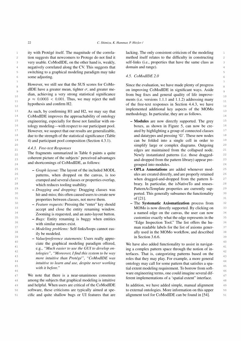
22 C. Shimizu, K. Hammar, P. Hitzler /
1 1
2 2
3 3
4 4
5 5
6 6
7 7
8 8
9 9
10 10
11 11
12 12
13 13
14 14
15 15
16 16
17 17
18 18
19 19
20 20
21 21
22 22
23 23
24 24
25 25
26 26
27 27
28 28
29 29
30 30
31 31
32 32
33 33
34 34
35 35
36 36
37 37
38 38
39 39
40 40
41 41
42 42
43 43
44 44
45 45
46 46
47 47
48 48
49 49
50 50
51 51
ity with Protégé itself. The magnitude of the correla-tion suggests that newcomers to Protege do not find itvery usable. CoModIDE, on the other hand is, weakly,negatively correlated along the CV. This suggests thatswitching to a graphical modeling paradigm may takesome adjusting.
However, we still see that the SUS scores for CoMo-dIDE have a greater mean, tighter σ, and greater me-dian, achieving a very strong statistical significancep ≈ 0.0003 < 0.001. Thus, we may reject the nullhypothesis and confirm H2.
As such, by confirming H1 and H2, we may say thatCoModIDE improves the approachability of ontologyengineering, especially for those not familiar with on-tology modeling—with respect to our participant pool.However, we suspect that our results are generalizable,due to the strength of the statistical significance (Table4) and participant pool composition (Section 4.3.1).
4.4.3. Free-text ResponsesThe fragments summarized in Table 6 paints a quitecoherent picture of the subjects’ perceived advantagesand shortcomings of CoModIDE, as follows:
– Graph layout: The layout of the included MODLpatterns, when dropped on the canvas, is toocramped and several classes or properties overlap,which reduces tooling usability.
– Dragging and dropping: Dragging classes washit-and-miss; this often caused users to create newproperties between classes, not move them.
– Feature requests: Pressing the “enter” key shouldaccept and close the entity renaming window.Zooming is requested, and an auto-layout button.
– Bugs: Entity renaming is buggy when entitieswith similar names exist.
– Modeling problems: Self-links/loops cannot eas-ily be modeled.
– Value/preference statements: Users really appre-ciate the graphical modeling paradigm offered,e.g., “Much easier to use the GUI to develop on-tologies”, “Moreover, I find this system to be waymore intuitive than Protégé”, “CoModIDE wasintuitive to learn and use, despite never workingwith it before.”
We note that there is a near-unanimous consensusamong the subjects that graphical modeling is intuitiveand helpful. When users are critical of the CoModIDEsoftware, these criticisms are typically aimed at spe-cific and quite shallow bugs or UI features that are
lacking. The only consistent criticism of the modelingmethod itself relates to the difficulty in constructingself-links (i.e., properties that have the same class asdomain and range).
4.5. CoModIDE 2.0
Since the evaluation, we have made plenty of progresson improving CoModIDE in significant ways. Asidefrom bug fixes and general quality of life improve-ments (i.e. versions 1.1.1 and 1.1.2) addressing manyof the free-text responses in Section 4.4.3, we haveimplemented additional key aspects of the MOMomethodology. In particular, they are as follows.
– Modules are now directly supported. The greyboxes, as shown in Figure 5, can now be cre-ated by highlighting a group of connected classesand datatypes and pressing ‘G’. These new nodescan be folded into a single cell in order tosimplify large or complex diagrams. Outgoingedges are maintained from the collapsed node.Newly instantiated patterns (i.e. those dragged-and-dropped from the pattern library) appear pre-grouped into modules.
– OPLa Annotations are added whenever mod-ules are created directly, and are properly retainedwhen dragged-and-dropped from the pattern li-brary. In particular, the isNativeTo and reuses-PatternAsTemplate properties are currently sup-ported. This generally subsumes the functionalityof [21].
– The Systematic Axiomatization process fromMOMo is now directly supported. By clicking ona named edge on the canvas, the user can nowcustomize exactly what the edge represents in the“Edge Inspection Tool.” The list offers the hu-man readable labels for the list of axioms gener-ally used in the MOMo workflow, and describedin Section 3.6.6.
We have also added functionality to assist in navigat-ing a complex pattern space through the notion of in-terfaces. That is, categorizing patterns based on theroles that they may play. For example, a more generalontology may call for some pattern that satisfies a spa-tial extent modeling requirement. To borrow from soft-ware engineering terms, one could imagine several dif-ferent implementations of a ‘spatial extent” interface.
In addition, we have added simple, manual alignmentto external ontologies. More information on this upperalignment tool for CoModIDE can be found in [54].

C. Shimizu, K. Hammar, P. Hitzler / 23
1 1
2 2
3 3
4 4
5 5
6 6
7 7
8 8
9 9
10 10
11 11
12 12
13 13
14 14
15 15
16 16
17 17
18 18
19 19
20 20
21 21
22 22
23 23
24 24
25 25
26 26
27 27
28 28
29 29
30 30
31 31
32 32
33 33
34 34
35 35
36 36
37 37
38 38
39 39
40 40
41 41
42 42
43 43
44 44
45 45
46 46
47 47
48 48
49 49
50 50
51 51
In order to improve the extensibility of the platform,we have reworked the overarching conceptual frame-work for functionality in CoModIDE. Functionality isnow categorized into so-called toolkits which commu-nicate through a newly implemented message bus. Thisallows for a relatively straightforward integration pro-cess for external developers.
It is also important to recall that CoModIDE is notjust a development platform, but a tool that enablesresearch into ontology engineering. To that point, wehave implemented an opt-in telemetry agent that col-lects and sends anonymized usage characteristics backto the developers. This records session lengths, clicks,and other such metrics that give us insight on how on-tologies are authored in a graphical environment.
5. Additional Infrastructure and Resources
5.1. The Modular Ontology Design Library (MODL)
The Modular Ontology Design Library (MODL) isboth an artifact and a framework for creating col-lections of ontology design patterns [20]. MODL isa method for establishing a well-curated and well-documented collection of ODPs that is structured us-ing OPLa. This allows for a queryable interface whenthe MODL is very large, or if the MODL is integratedinto other tooling infrastructure. For example, CoMo-dIDE uses OPLa annotations to structure, define, andrelate patterns in its internal MODL, as described inSection 4.1.
5.2. OPLa Annotator
The OPLa Annotator [21] is a standalone plugin forProtégé. This plug-in allows for the guided creation ofopla:isNativeTo annotations on ontological entities ofan OWL file. While this particular functionality is sub-sumed in CoModIDE, it does not require the graphicalcanvas or the creation of modules, and can be a quickeroption when the imposed graphical organization is notdesired or required.
5.3. ROWLTab
ROWLTab [48] is another standalone plugin for Pro-tégé. It is based on the premise that some ontologyusers, and frequently non-ontologists, find conceptual-izing knowledge through rules to be more convenient.
This plugin allows the user to enter SWRL rules whichwill then, when applicable, be converted into equiv-alent OWL axioms. An extension to this plug-in, de-tailed in [55], allows for existential rules.
5.4. SDOnt
SDOnt [19] is an early tool for generating schema dia-grams from OWL files. Unlike other visual OWL gen-erators, SDOnt does not give a strictly disambiguousdiagram. Instead, it generates schema diagrams in thestyle that has been described in Section 3.2 based onthe TBox of the input OWL file. This program only re-quires Java to run and can be run on any OWL ontol-ogy; although, as with any graph visualization, it tendsto work best with smaller schemas.
5.5. Example Modular Ontologies
In this section, we provide a brief directory of ex-isting modular ontologies, organized by modelingchallenges. These can be used for inspiration to theprospective modeler, or, in the spirit of the MOMomethodology, the modeler may wish to reuse or adapttheir modules to new or similar use cases.
Highly Spatial DataIt is frequently common to model data that has a strongspatial dimension. The challenges that accompany thisare unfortunately myriad. In the GeoLink Modular On-tology [56] we utilize the Semantic Trajectory pat-tern to model discrete representations of continuousspatial movement. Ongoing work regarding the inte-gration of multiple datasets (e.g., NOAA storm data,USGS earthquake data, and FEMA disaster declara-tions)17 while using their spatial data as the dimensionof integration can be found online18. The RealEstate-Core Ontology [33, 57] provides a set of patterns andmodules for the integration of spatial footprints andstructures in a real estate property with sensors andother devices present on the Internet of Things.
Elusive Ground TruthSometimes, it is necessary to model data where it is notknown if it is true, or that it is necessary to knowinglyingest possibly contradictory knowledge. In this case,we suggest a records-based approach, with a strong
17Respectively, these are National Oceanic and Atmospheric Ad-ministration, United States Geological Survey, and Federal Emer-gency Management Agency.
18See https://knowwheregraph.org/
24 C. Shimizu, K. Hammar, P. Hitzler /
1 1
2 2
3 3
4 4
5 5
6 6
7 7
8 8
9 9
10 10
11 11
12 12
13 13
14 14
15 15
16 16
17 17
18 18
19 19
20 20
21 21
22 22
23 23
24 24
25 25
26 26
27 27
28 28
29 29
30 30
31 31
32 32
33 33
34 34
35 35
36 36
37 37
38 38
39 39
40 40
41 41
42 42
43 43
44 44
45 45
46 46
47 47
48 48
49 49
50 50
51 51
emphasis on the first-class modeling of provenance.That is, knowledge or data is not modeled directly, butinstead we model a container for the data, which isthen strongly connected to its provenance. An exampleof this approach can be found in the Enslaved Ontol-ogy [44], where historical data may contradict or con-flict with itself, based on the interpretations of differenthistorians.
Rule-based KnowledgeIn some cases, it may be necessary to directly encoderules or conditional data, such as attempting to de-scribe the action-response mechanisms when reactingto an event. The methods for doing so, and the mod-ules therein associated, can be found in the ModularOntology for Space Weather Research [58] and in theDomain Ontology for Task Instructions [? ].
Shortcuts & ViewsShortcuts and Views are used to manage complexitybetween rich and detailed ontological truthiness andconvenience for data providers, publishers, and con-sumers. That is, it is frequently desirable to have highfidelity in the underlying knowledge model, whichmay result in a model that is confusing or unintuitiveto the non-ontologist. As such, shortcuts can be usedto simplify navigation or publishing according to themodel. These shortcuts would also be formally de-scribed allowing for a navigation between levels of ab-straction. A full examination of these constructs is outof scope, but examples of shortcuts and views, along-side their use, can be found in the Geolink ModularOntology [56], the tutorial for modeling Chess GameData [59], and in the Enslaved Ontology [44].
6. Conclusion
The re-use of ontologies for new purposes, or adapt-ing them to new use-cases, is frequently very diffi-cult. In our experiences, we have found this to be thecase for several reasons: (i) differing representationalgranularity, (ii) lack of conceptual clarity of the ontol-ogy design, (iii) adhering to good modeling principles,and (iv) a lack of re-use emphasis and process supportavailable in ontology engineering tooling. In order toaddress these concerns, we have developed the Mod-ular Ontology Modeling (MOMo) workflow and sup-porting tooling infrastructure, CoModIDE (The Com-prehensive Modular Ontology Integrated DevelopmentEnvironment – “commodity”).
In this paper, we have presented the MOMo work-flow in detail, from introducing the schema diagram asthe primary conceptual vehicle for communicating be-tween ontology engineers and domain experts, to pre-senting several experiences in executing the workflowacross many distinct domains with different use casesand data requirements.
We have also shown how the CoModIDE platformallows ontology engineers, irrespective of previousknowledge level, to develop ontologies more correctlyand more quickly, than by using standard Protégé; thatCoModIDE has a higher usability (SUS score) thanstandard Protégé; and that the CoModIDE issues thatconcern users primarily derive from shallow bugs asopposed to methodological or modeling issues. Takentogether, this implies that the modular graphical ontol-ogy engineering paradigm is a viable way for support-ing the MOMo workflow.
6.1. Future Work
From here, there are still many avenues of investiga-tion remaining, pertaining to both the MOMo work-flow and CoModIDE.
Regarding the workflow, we will continue to exe-cute the workflow in new domains and observe differ-ences in experiences. Currently, we are examining howto better incorporate spatially-explicit modeling tech-niques. In addition, we wish to further explore howschema diagrams may represent distinctly different se-mantics, such as ShEx [60], SHACL [61], rather thanOWL.
We also foresee the continued development of the plat-form. As mentioned in Section 4.5, we have improvedits internal structure so that it may support bundledpieces of functionality. In particular, we will developsuch toolkits for supporting holistic ontology engineer-ing projects, going beyond just the modeling process.This will include the incorporation of ontology align-ment systems so that CoModIDE may export auto-matic alignments alongside the designed deliverable,and the incorporation of recommendation software,perhaps based on input seed data. Further, we see aroute for automatic documentation in the style of ourown technical reports. Finally, we wish to examine col-lected telemetry data in order to analyse how users de-velop ontologies in a graphical modeling paradigm.
Acknowledgements. Cogan Shimizu and Pascal Hit-zler acknowledge partial support from the financial

C. Shimizu, K. Hammar, P. Hitzler / 25
1 1
2 2
3 3
4 4
5 5
6 6
7 7
8 8
9 9
10 10
11 11
12 12
13 13
14 14
15 15
16 16
17 17
18 18
19 19
20 20
21 21
22 22
23 23
24 24
25 25
26 26
27 27
28 28
29 29
30 30
31 31
32 32
33 33
34 34
35 35
36 36
37 37
38 38
39 39
40 40
41 41
42 42
43 43
44 44
45 45
46 46
47 47
48 48
49 49
50 50
51 51
assistance award 70NANB19H094 from U.S. Depart-ment of Commerce, National Institute of Standardsand Technology and the National Science Foundationunder Grant No. 2033521 and the Andrew W. Mel-lon Foundation. The authors acknowledge the help-ful input from Adila Krisnadhi and MD Kamruzza-man Sarker; and development support from SulognaChowdhury, Abhilekha Dalal, Riley Mueller, and LuZhou.
References
[1] Gene Ontology Consortium: The Gene Ontology(GO) database and informatics resource, NucleicAcids Research 32(Database–Issue) (2004), 258–261.doi:10.1093/nar/gkh036.
[2] P. Hitzler, A Review of the Semantic Web Field, Commun.ACM 64(2) (2021), 76–83. doi:10.1145/3397512.
[3] Linked Open Vocabularies (LOV), Accessed: 2021-05-06.https://lov.linkeddata.es/dataset/lov/.
[4] A. Algergawy, D. Faria, A. Ferrara, I. Fundulaki, I. Harrow,S. Hertling, E. Jiménez-Ruiz, N. Karam, A. Khiat, P. Lam-brix, H. Li, S. Montanelli, H. Paulheim, C. Pesquita, T. Saveta,P. Shvaiko, A. Splendiani, É. Thiéblin, C. Trojahn, J. Vatas-cinová, O. Zamazal and L. Zhou, Results of the OntologyAlignment Evaluation Initiative 2019, in: Proceedings of the14th International Workshop on Ontology Matching co-locatedwith the 18th International Semantic Web Conference (ISWC2019), Auckland, New Zealand, October 26, 2019, P. Shvaiko,J. Euzenat, E. Jiménez-Ruiz, O. Hassanzadeh and C. Trojahn,eds, CEUR Workshop Proceedings, Vol. 2536, CEUR-WS.org,2019, pp. 46–85.
[5] O. Zamazal and V. Svátek, The Ten-Year OntoFarm and its Fer-tilization within the Onto-Sphere, J. Web Semant. 43 (2017),46–53. doi:10.1016/j.websem.2017.01.001.
[6] K. Hammar, Content Ontology Design Patterns: Qualities,Methods, and Tools, PhD thesis, 2017.
[7] A. Algergawy, S. Babalou, F. Klan and B. König-Ries, Ontol-ogy Modularization with OAPT, J. Data Semant. 9(2) (2020),53–83. doi:10.1007/s13740-020-00114-7.
[8] B.C. Grau, I. Horrocks, Y. Kazakov and U. Sattler, Extract-ing Modules from Ontologies: A Logic-Based Approach, in:Modular Ontologies: Concepts, Theories and Techniques forKnowledge Modularization, H. Stuckenschmidt, C. Parent andS. Spaccapietra, eds, Lecture Notes in Computer Science,Vol. 5445, Springer, 2009, pp. 159–186. doi:10.1007/978-3-642-01907-4_8.
[9] H. Stuckenschmidt, C. Parent and S. Spaccapietra (eds),Modular Ontologies: Concepts, Theories and Techniques forKnowledge Modularization, Lecture Notes in Computer Sci-ence, Vol. 5445, Springer, 2009. ISBN 978-3-642-01906-7.doi:10.1007/978-3-642-01907-4.
[10] D. Osumi-Sutherland, M. Courtot, J.P. Balhoff andC.J. Mungall, Dead simple OWL design patterns, J. Biomed.Semant. 8(1) (2017), 18:1–18:7. doi:10.1186/s13326-017-0126-0.
[11] M.G. Skjæveland, D.P. Lupp, L.H. Karlsen and H. Forssell,Practical Ontology Pattern Instantiation, Discovery, and Main-tenance with Reasonable Ontology Templates, in: The Seman-tic Web - ISWC 2018 - 17th International Semantic Web Con-ference, Monterey, CA, USA, October 8-12, 2018, Proceedings,Part I, D. Vrandecic, K. Bontcheva, M.C. Suárez-Figueroa,V. Presutti, I. Celino, M. Sabou, L. Kaffee and E. Simperl,eds, Lecture Notes in Computer Science, Vol. 11136, Springer,2018, pp. 477–494. doi:10.1007/978-3-030-00671-6_28.
[12] E. Blomqvist and K. Sandkuhl, Patterns in Ontology Engi-neering: Classification of Ontology Patterns, in: ICEIS 2005,Proceedings of the Seventh International Conference on En-terprise Information Systems, Miami, USA, May 25-28, 2005,C. Chen, J. Filipe, I. Seruca and J. Cordeiro, eds, 2005,pp. 413–416.
[13] A. Gangemi, Ontology Design Patterns for Semantic WebContent, in: The Semantic Web - ISWC 2005, 4th Interna-tional Semantic Web Conference, ISWC 2005, Galway, Ire-land, November 6-10, 2005, Proceedings, Y. Gil, E. Motta,V.R. Benjamins and M.A. Musen, eds, Lecture Notes inComputer Science, Vol. 3729, Springer, 2005, pp. 262–276.doi:10.1007/11574620_21.
[14] P. Hitzler, A. Gangemi, K. Janowicz, A. Krisnadhi and V. Pre-sutti (eds), Ontology Engineering with Ontology Design Pat-terns – Foundations and Applications, Studies on the SemanticWeb, Vol. 25, IOS Press, 2016.
[15] Y. Hu, K. Janowicz, D. Carral, S. Scheider, W. Kuhn, G. Berg-Cross, P. Hitzler, M. Dean and D. Kolas, A geo-ontology de-sign pattern for semantic trajectories, in: International Con-ference on Spatial Information Theory, T. Tenbrink, J. Stell,A. Galton and Z. Wood, eds, Springer, 2013, pp. 438–456.
[16] K. Hammar and V. Presutti, Template-Based Content ODPInstantiation, in: Advances in Ontology Design and Patterns[revised and extended versions of the papers presented atthe 7th edition of the Workshop on Ontology and SemanticWeb Patterns, WOP@ISWC 2016, Kobe, Japan, 18th October2016], K. Hammar, P. Hitzler, A. Krisnadhi, A. Lawrynowicz,A.G. Nuzzolese and M. Solanki, eds, Studies on the SemanticWeb, Vol. 32, IOS Press, 2016, pp. 1–13. doi:10.3233/978-1-61499-826-6-1.
[17] E. Blomqvist, K. Hammar and V. Presutti, Engineering On-tologies with Patterns - The eXtreme Design Methodology, in:Ontology Engineering with Ontology Design Patterns - Foun-dations and Applications, P. Hitzler, A. Gangemi, K. Janow-icz, A. Krisnadhi and V. Presutti, eds, Studies on the SemanticWeb, Vol. 25, IOS Press, 2016, pp. 23–50. doi:10.3233/978-1-61499-676-7-23.
[18] C. Shimizu, K. Hammar and P. Hitzler, Modular Graphi-cal Ontology Engineering Evaluated, in: The Semantic Web -17th International Conference, ESWC 2020, Heraklion, Crete,Greece, May 31-June 4, 2020, Proceedings, A. Harth, S. Kir-rane, A.N. Ngomo, H. Paulheim, A. Rula, A.L. Gentile,P. Haase and M. Cochez, eds, Lecture Notes in Computer Sci-ence, Vol. 12123, Springer, 2020, pp. 20–35. doi:10.1007/978-3-030-49461-2_2.
[19] C. Shimizu, A. Eberhart, N. Karima, Q. Hirt, A. Krisnadhi andP. Hitzler, A Method for Automatically Generating Schema Di-agrams for OWL Ontologies, in: Knowledge Graphs and Se-mantic Web - First Iberoamerican Conference, KGSWC 2019,Villa Clara, Cuba, June 23-30, 2019, Proceedings, B. Villazón-Terrazas and Y. Hidalgo-Delgado, eds, Communications in

26 C. Shimizu, K. Hammar, P. Hitzler /
1 1
2 2
3 3
4 4
5 5
6 6
7 7
8 8
9 9
10 10
11 11
12 12
13 13
14 14
15 15
16 16
17 17
18 18
19 19
20 20
21 21
22 22
23 23
24 24
25 25
26 26
27 27
28 28
29 29
30 30
31 31
32 32
33 33
34 34
35 35
36 36
37 37
38 38
39 39
40 40
41 41
42 42
43 43
44 44
45 45
46 46
47 47
48 48
49 49
50 50
51 51
Computer and Information Science, Vol. 1029, Springer, 2019,pp. 149–161. doi:10.1007/978-3-030-21395-4_11.
[20] C. Shimizu, Q. Hirt and P. Hitzler, MODL: A Modular Ontol-ogy Design Library, in: WOP@ISWC, CEUR Workshop Pro-ceedings, Vol. 2459, CEUR-WS.org, 2019, pp. 47–58.
[21] C. Shimizu, Q. Hirt and P. Hitzler, A Protégé Plug-In for An-notating OWL Ontologies with OPLa, in: The Semantic Web:ESWC 2018 Satellite Events - ESWC 2018 Satellite Events,Heraklion, Crete, Greece, June 3-7, 2018, Revised Selected Pa-pers, A. Gangemi, A.L. Gentile, A.G. Nuzzolese, S. Rudolph,M. Maleshkova, H. Paulheim, J.Z. Pan and M. Alam, eds, Lec-ture Notes in Computer Science, Vol. 11155, Springer, 2018,pp. 23–27. doi:10.1007/978-3-319-98192-5_5.
[22] M. Fernández-López, A. Gómez-Pérez and N. Juristo,METHONTOLOGY: From Ontological Art Towards Ontolog-ical Engineering, Technical Report, SS-97-06, American As-sociation for Artificial Intelligence, 1997.
[23] Y. Sure, S. Staab and R. Studer, On-To-Knowledge Method-ology (OTKM), in: Handbook on Ontologies, S. Staab andR. Studer, eds, International Handbooks on Information Sys-tems, Springer Berlin Heidelberg, 2004, pp. 117–132.
[24] H.S. Pinto, S. Staab, C. Tempich and Y. Sure, Distributed En-gineering of Ontologies (DILIGENT), in: Semantic Web andPeer-to-Peer: Decentralized Management and Exchange ofKnowledge and Information, S. Staab and H. Stuckenschmidt,eds, Springer, 2006, pp. 303–322.
[25] W.C. Mann and S.A. Thompson, Rhetorical Structure Theory:A Theory of Text Organization, Information Sciences Institute,University of Southern California, Los Angeles, 1987.
[26] M. Egaña, E. Antezana and R. Stevens, Transforming the Ax-iomisation of Ontologies: The Ontology Pre-Processor Lan-guage, in: Proceedings of the Fourth OWLED Workshop onOWL: Experiences and Directions, K. Clark and P.F. Patel-Schneider, eds, CEUR Workshop Proceedings, 2008.
[27] N. Karima, K. Hammar and P. Hitzler, How to Document On-tology Design Patterns, in: Advances in Ontology Design andPatterns, K. Hammar, P. Hitzler, A. Lawrynowicz, A. Kris-nadhi, A. Nuzzolese and M. Solanki, eds, Studies on the Se-mantic Web, Vol. 32, IOS Press, Amsterdam, 2017, pp. 15–28.
[28] Q. Hirt, C. Shimizu and P. Hitzler, Extensions to the OntologyDesign Pattern Representation Language, in: WOP@ISWC,CEUR Workshop Proceedings, Vol. 2459, CEUR-WS.org,2019, pp. 76–75.
[29] P. Hitzler, A. Gangemi, K. Janowicz, A.A. Krisnadhi andV. Presutti, Towards a Simple but Useful Ontology DesignPattern Representation Language, in: Proceedings of the 8thWorkshop on Ontology Design and Patterns (WOP 2017)co-located with the 16th International Semantic Web Con-ference (ISWC 2017), Vienna, Austria, October 21, 2017.,E. Blomqvist, Ó. Corcho, M. Horridge, D. Carral and R. Hoek-stra, eds, CEUR Workshop Proceedings, Vol. 2043, CEUR-WS.org, 2017. http://ceur-ws.org/Vol-2043/paper-09.pdf.
[30] K. Hammar, Ontology Design Patterns in WebProtégé, in: Pro-ceedings of the ISWC 2015 Posters & Demonstrations Trackco-located with the 14th International Semantic Web Confer-ence (ISWC-2015), Bethlehem, PA, USA, October 11, 2015.,S. Villata, J.Z. Pan and M. Dragoni, eds, CEUR Workshop Pro-ceedings, Vol. 1486, CEUR-WS.org, 2015. http://ceur-ws.org/Vol-1486/paper_50.pdf.
[31] E. Blomqvist, A. Gangemi and V. Presutti, Experiments onpattern-based ontology design, in: Proceedings of the fifth in-ternational conference on Knowledge capture, 2009, pp. 41–48.
[32] E. Blomqvist, V. Presutti, E. Daga and A. Gangemi, Ex-perimenting with eXtreme design, in: International Confer-ence on Knowledge Engineering and Knowledge Management,Springer, 2010, pp. 120–134.
[33] K. Hammar, Ontology design patterns in use: lessons learntfrom an ontology engineering case, in: Workshop on OntologyPatterns in conjunction with the 11th International SemanticWeb Conference 2012 (ISWC 2012), 2012.
[34] S. Peroni, A Simplified Agile Methodology for Ontology De-velopment, in: OWL: Experiences and Directions – ReasonerEvaluation, M. Dragoni, M. Poveda-Villalón and E. Jimenez-Ruiz, eds, Lecture Notes in Computer Science, Vol. 10161,Springer, 2017, pp. 55–69.
[35] I. Hadar and P. Soffer, Variations in conceptual modeling: clas-sification and ontological analysis, Journal of the Associationfor Information Systems 7(8) (2006), 20.
[36] P. Shoval and I. Frumermann, OO and EER conceptualschemas: a comparison of user comprehension, Journal ofDatabase Management (JDM) 5(4) (1994), 28–38.
[37] S.S.-S. Cherfi, J. Akoka and I. Comyn-Wattiau, Conceptualmodeling quality-from EER to UML schemas evaluation, in:International Conference on Conceptual Modeling, Springer,2002, pp. 414–428.
[38] R. Agarwal and A.P. Sinha, Object-oriented modeling withUML: a study of developers’ perceptions, Communications ofthe ACM 46(9) (2003), 248–256.
[39] J. Krogstie, Evaluating UML using a generic quality frame-work, in: UML and the Unified Process, IGI Global, 2003,pp. 1–22.
[40] S. Lohmann, S. Negru, F. Haag and T. Ertl, Visualizing ontolo-gies with VOWL, Semantic Web 7(4) (2016), 399–419.
[41] S. Lohmann, V. Link, E. Marbach and S. Negru, WebVOWL:Web-based visualization of ontologies, in: International Con-ference on Knowledge Engineering and Knowledge Manage-ment, Springer, 2014, pp. 154–158.
[42] V. Wiens, S. Lohmann and S. Auer, WebVOWL Editor:Device-Independent Visual Ontology Modeling, in: Proceed-ings of the ISWC 2018 Posters & Demonstrations, Industryand Blue Sky Ideas Tracks, CEUR Workshop Proceedings,Vol. 2180, 2018.
[43] M.K. Sarker, A.A. Krisnadhi and P. Hitzler, OWLAx: A Pro-tégé Plugin to Support Ontology Axiomatization through Di-agramming, in: Proceedings of the ISWC 2016 Posters &Demonstrations Track co-located with 15th International Se-mantic Web Conference (ISWC 2016), Kobe, Japan, October19, 2016., T. Kawamura and H. Paulheim, eds, CEUR Work-shop Proceedings, Vol. 1690, CEUR-WS.org, 2016.
[44] C. Shimizu, P. Hitzler, Q. Hirt, D. Rehberger, S.G. Estrecha,C. Foley, A.M. Sheill, W. Hawthorne, J. Mixter, E. Watrall,R. Carty and D. Tarr, The Enslaved Ontology: Peoples ofthe historic slave trade, Journal of Web Semantics 63 (2020),100567. doi:10.1016/j.websem.2020.100567.
[45] S. Sahoo, D. McGuinness and T. Lebo, PROV-O: ThePROV Ontology, W3C Recommendation, W3C, 2013,http://www.w3.org/TR/2013/REC-prov-o-20130430/.

C. Shimizu, K. Hammar, P. Hitzler / 27
1 1
2 2
3 3
4 4
5 5
6 6
7 7
8 8
9 9
10 10
11 11
12 12
13 13
14 14
15 15
16 16
17 17
18 18
19 19
20 20
21 21
22 22
23 23
24 24
25 25
26 26
27 27
28 28
29 29
30 30
31 31
32 32
33 33
34 34
35 35
36 36
37 37
38 38
39 39
40 40
41 41
42 42
43 43
44 44
45 45
46 46
47 47
48 48
49 49
50 50
51 51
[46] P. Hitzler and A. Krisnadhi, On the Roles of Logical Axiom-atizations for Ontologies, in: Ontology Engineering with On-tology Design Patterns – Foundations and Applications, P. Hit-zler, A. Gangemi, K. Janowicz, A. Krisnadhi and V. Presutti,eds, Studies on the Semantic Web, Vol. 25, IOS Press, 2016,pp. 73–80. doi:10.3233/978-1-61499-676-7-73.
[47] M.K. Sarker, D. Carral, A.A. Krisnadhi and P. Hitzler, Mod-eling OWL with Rules: The ROWL Protege Plugin, in: Pro-ceedings of the ISWC 2016 Posters & Demonstrations Trackco-located with 15th International Semantic Web Conference(ISWC 2016), Kobe, Japan, October 19, 2016, T. Kawa-mura and H. Paulheim, eds, CEUR Workshop Proceedings,Vol. 1690, CEUR-WS.org, 2016.
[48] M.K. Sarker, A. Krisnadhi, D. Carral and P. Hitzler, Rule-Based OWL Modeling with ROWLTab Protégé Plugin, in:The Semantic Web – 14th International Conference, ESWC2017, Portorož, Slovenia, May 28 – June 1, 2017, Proceedings,Part I, E. Blomqvist, D. Maynard, A. Gangemi, R. Hoekstra,P. Hitzler and O. Hartig, eds, Lecture Notes in Computer Sci-ence, Vol. 10249, 2017, pp. 419–433. doi:10.1007/978-3-319-58068-5_26.
[49] C. Shimizu, A. Krisnadhi and P. Hitzler, On the Roles of Log-ical Axiomatizations for Ontologies, in: Aplications and Prac-tices in Ontology Design, Extration, and Reasoning, G. Cota,M. Daquino and G.L. Pozzato, eds, Studies on the SemanticWeb, IOS Press, to appear.
[50] C. Shimizu, P. Hitzler, Q. Hirt, A. Shiell, S. Gonzalez, C. Fo-ley, D. Rehberger, E. Watrall, W. Hawthorne, D. Tarr, R. Cartyand J. Mixter, The Enslaved Ontology 1.0: People of the His-toric Slave Trade, Technical Report, Michigan State University,East Lansing, Michigan, 2019, available from https://daselab.cs.ksu.edu/projects/ontology-modeling-slave-trade.
[51] K. Hammar, Ontology design pattern property specialisa-tion strategies, in: International Conference on KnowledgeEngineering and Knowledge Management, Springer, 2014,pp. 165–180.
[52] P. Burnard, A method of analysing interview transcripts inqualitative research, Nurse education today 11(6) (1991), 461–466.
[53] C.B. Seaman, Qualitative methods, in: Guide to advanced em-pirical software engineering, Springer, 2008, pp. 35–62.
[54] A. Dalal, C. Shimizu and P. Hitzler, Modular Ontology Model-ing Meets Upper Ontologies: The Upper Ontology AlignmentTool, in: Proceedings of the ISWC 2020 Posters & Demon-
strations Track co-located with the 19th International Seman-tic Web Conference (ISWC 2020), Kobe, Japan, November 3,2020, 2020, In Press.
[55] S.J. Satpathy, Rules with Right hand Existential or Disjunc-tion with ROWLTab, Master’s thesis, Wright State University,2019.
[56] A. Krisnadhi, Y. Hu, K. Janowicz, P. Hitzler, R.A. Arko, S. Car-botte, C. Chandler, M. Cheatham, D. Fils, T.W. Finin, P. Ji,M.B. Jones, N. Karima, K.A. Lehnert, A. Mickle, T.W. Narock,M. O’Brien, L. Raymond, A. Shepherd, M. Schildhauer andP. Wiebe, The GeoLink Modular Oceanography Ontology,in: The Semantic Web - ISWC 2015 - 14th International Se-mantic Web Conference, Bethlehem, PA, USA, October 11-15,2015, Proceedings, Part II, M. Arenas, Ó. Corcho, E. Simperl,M. Strohmaier, M. d’Aquin, K. Srinivas, P.T. Groth, M. Du-montier, J. Heflin, K. Thirunarayan and S. Staab, eds, Lec-ture Notes in Computer Science, Vol. 9367, Springer, 2015,pp. 301–309. doi:10.1007/978-3-319-25010-6_19.
[57] K. Hammar, E.O. Wallin, P. Karlberg and D. Hälleberg, TheRealEstateCore Ontology, in: The Semantic Web – ISWC2019, Lecture Notes in Computer Science, Vol. 11779,Springer, Cham, 2019, pp. 130–145. https://doi.org/10.1007/978-3-030-30796-7_9.
[58] C. Shimizu, R. McGranaghan, A. Eberhart and A.C. Keller-man, Towards a Modular Ontology for Space Weather Re-search, in: Advances in Pattern-Based Ontology Engineer-ing, E. Blomqvist, T. Hahmann, K. Hammar, P. Hitzler,R. Hoekstra, R. Mutharaju, M. Poveda-Villalón, C. Shimizu,M.G.S. nd Monika Solanki, V. Svátek and L. Zhou, eds, Stud-ies on the Semantic Web, Vol. 51, IOS Press, 2021.
[59] A. Krisnadhi and P. Hitzler, Modeling With Ontology De-sign Patterns: Chess Games As a Worked Example, in: On-tology Engineering with Ontology Design Patterns - Founda-tions and Applications, P. Hitzler, A. Gangemi, K. Janowicz,A. Krisnadhi and V. Presutti, eds, Studies on the Semantic Web,Vol. 25, IOS Press, 2016, pp. 3–21. doi:10.3233/978-1-61499-676-7-3.
[60] T. Baker and E. Prud’hommeaux (eds), Shape Expressions(ShEx) 2.1 Primer, Final Community Group Report 09 October2019, 2019, http://shex.io/shex-primer/index.html.
[61] H. Knublauch and D. Kontokostas (eds), Shapes ConstraintLanguage (SHACL), W3C Recommendation 20 July 2017,2017, https://www.w3.org/TR/shacl/.