modular process equipment for low cost manufacturing of ... · pdf filemodular process...
TRANSCRIPT
Modular Process Equipment for Low Cost Manufacturing of High Capacity Prismatic Li-Ion Cell Alloy Anodes 2014 DOE Vehicle Technologies Program Annual Merit Review
Project ID#: ES128 Principal Investigator: Sergey D. Lopatin Project Manager: Ajey M. Joshi Corporate CTO Office Energy Storage Solutions June 16 - 20, 2014
This presentation does not contain any proprietary, confidential, or otherwise restricted information

Overview Modular Process Equipment for Low Cost Manufacturing of High Capacity Prismatic Li-Ion Cell Alloy Anodes PROJECT TIMELINE
Start: 10/01/2011 | End: 09/30/2014 | ~69% Complete BUDGET
Total Project Funding: $4.90M (51%) DOE Share $4.63M (49%) Applied Materials FY13 Funding Received: $1.60M FY14 Funding Expected: $1.70M DOE Share
BARRIERS ADDRESSED • Cost of manufacturing • Cycling lifetime of high capacity materials • Prismatic cell format
PARTNERS • J. Nanda, Oak Ridge National Laboratory • G. Liu, Lawrence Berkeley National Laboratory • M. Yakovleva, FMC Lithium • P. Hagans, Navitas (former A123 Systems division) • K. Oshihara, Nissan-TCNA
2

Response to Reviewers Comments Relevance Comments: The reviewers stated that this project has very strong relevance for the DOE goals of reducing the use of petroleum products to power vehicles. They noted that this unique manufacturing approach delivers a unique anode, which could facilitate appreciably higher performing EV cells. Response: Navitas Systems is evaluating the Applied Materials electrodes using testing equipment for half coin cell, full coin cell, and full scale 63450 prismatic cell geometries. Finally, the Nissan Technical Center (North America) has a researcher who is conducting cell performance measurements and final cell validation to USABC requirements.
Approach Comments: One reviewer indicated that the equipment manufactured by Applied Materials will reduce the manufacturing cost of anodes. The reviewer stated that the coating width to meet the cost goals is needed for the success of the coating equipment. Response: Cost remains a question at this point, it will be part of the final deliverable for reducing the manufacturing cost of anodes. This technology is expected to be scalable.
Technical Accomplishments Comments: The mechanical stability of this material may be a critical issue and should be addressed. The reviewer concluded that the key technical risks have to do with improving the process for forming the electrodes. Response: Stanford Linear Accelerator Center granted beam-time for better understanding and controlling the stability of this material.
3

Objectives & Scope A. PROJECT OBJECTIVES
The objective of this project is to research, develop, and demonstrate novel high capacity Li-ion battery cell anodes that are capable of achieving an energy density of at least 500 Watthours per liter (Wh/l) and a power density of at least 500 Watts per liter (W/l) while maintaining comparable performance standards in terms of cycle life (300-1000 cycles at 80% depth of discharge), calendar life (5-10 years), and durable cell construction and design capable of being affordably mass produced.
4
Relevance
B. PROJECT SCOPE The project includes research, development, test, and demonstration of an advanced High Volume Manufacturing (HVM) prototype module for fabricating high capacity Li-ion anodes in a continuous roll-to-roll configuration at low cost. The HVM prototype module will manufacture a new class of Li battery anodes with a high capacity based on an innovative micro-cell porous 3D Cu – Li alloy structure. The project will focus on demonstrating the innovative high rate deposition technique suitable for the micro-cell porous 3D Cu – Li alloy architecture.

Technical Summary BASELINE CHARACTERIZATION A cell level design model has been developed for two chemistry combinations: Baseline cell having
Li1-x(Ni1/3Mn1/3Co1/3)O2 (NMC333) positive electrode with 3D Cu Graphite negative electrode, and
Interim cell having NMC positive electrode with 3D CuSn negative electrode.
5
Approach, Accomplishments and Progress
TECHNOLOGY DESIGN Experimental development focused on concept design of initial electro-deposition module which allows for 3D porous structure formation in a single prototype tool for both 3D Cu collector and 3D CuSnFe alloy anode coating. Baseline processes have been developed for (a)
3D Cu current collector and (b) for graphite coating using a water soluble process.
Scanning Electron Microscopy (SEM) analysis of 3D Cu graphite structures shows pore fill and crack-free coating. Preliminary testing rate performance in half-cell assembly vs. Li demonstrated capacity retention advantages at 2C and 3C.
TECHNOLOGY DEVELOPMENT For the high capacity, we have developed CuSnFe electro-deposition process and obtained nano-structure alloy for high loading NMC / CuSnFe cell testing.

Technical Summary
6
Approach, Accomplishments and Progress
TECHNOLOGY DEVELOPMENT Eighteen cells comprised the program’s 1st deliverable were sent to Idaho National Laboratory
(INL) for further evaluation. Development of electro-deposition module which allows for 3D-porous structure formation in a
single prototype tool for both 3DCu collector and 3DCuSnFe alloy anode. Development of modular technological steps for forming 2.5-4.5 mAh/cm2 cells including
process methodology for Graphite coating by water soluble process to achieve adhesion to the 3D-porous structures. Testing rate performance in half-cell assembly vs. Li demonstrated capacity retention advantages up to 25-27% at 2C and 3C-rates.
Testing baseline pouch cell assembly. Porous 3D electrodes were assembled in single layer pouch cells with Li1-x[Ni1/3Mn1/3Co1/3]O2 (NMC) cathodes.The retention capacity for 3DCu/Graphite vs. NMC was measured 81.8% at 1310 cycles. Projection from these data is that the baseline cell is capable of over 1400 cycles at capacity retention of 80% at C/3 rate.
Development of 3DCuSnFe nano-structure alloy anode. Coulombic efficiency (CE) is improved by grain size reduction, pre-lithiation, and mitigation with combining alloy with Graphite.
Extending 3D electrode concept to the high loading 3DCuSnFe/Graphite alloy electrodes and testing interim pouch cell. The retention capacity of 76.2% at 1280 cycles was demonstrated. These data show that the interim cell is capable of 985 cycles at 80% capacity retention at C/3 rate.

Prototype Equipment Electro-Deposition
7
Accomplishments and Progress

3D CuSnFe High Resolution Images
TEM 50 nm grain sizes of anode alloy
with Cu6Sn5(Fe) structure
SEM Connected nano-grains form network of porous active material on Cu foil
8
Accomplishments and Progress

Structural Analysis 3D Cu Plated on Cu Foil
9
TOP VIEW
100 µm 10 µm
CROSS-SECTIONAL VIEW
Accomplishments and Progress
3D Cu porous structure showing micro, meso and nano porosity

Cap
acity
, mAh
/g
Collaboration: Navitas (former A123 (cell development)), FMC (pre-lithiation), LBNL(conductive binder) Nissan-TCNA (testing), ORNL (characterization)
1000
500
250
750
3D Cu + Graphite
3D CuSnFe + Si
Sn 2.5 V 360 s, porous Cu 8 V 25 s, 200 C for 20 min
0
200
400
600
800
1000
1200
1 6 11 16 21 26 31Cycle number
Cap
acity
(mA
h/g)
0
20
40
60
80
100
Effic
ienc
y (%
)
LithiationDelithiationEfficiency
Current Technology
Goal: to Develop Next Generation 3D Anode 700-1200 mAh/g
400-600 mAh/g
3D electrode concept
Si
Cu 3D CuSnFe
Reduced Anode Cost ($/m2) and ($/Wh) at Higher Performance
3D Cu Anode Development Roadmap
10
Capacity Current loading Cycling lifetime

HALF-CELLS: BASELINE 3D Cu/GRAPHITE ANODE and INTERIM I and II 3D CuSnFe/GRAPHITE ANODES
Accomplishments and Progress Results Interim Cell Test
Cap
acity
, mAh
/cm
2
3DCuSnFe/Graphite material – same or higher capacity with 30% thickness reduction
11

Half Cell Comparison (Interim vs. Baseline)
Capacity/mAh3.532.521.510.50
Volta
ge/V
2
1.8
1.6
1.4
1.2
1
0.8
0.6
0.4
0.2
3D Cu/Gr (3.0mAh/cm2)
CuSnFe/Gr (3.7mAh/cm2)
Electrode area: 0.97 cm2
Capacity/mAh340320300280260240220200180160140120100806040200
Vol
tage
/V
2
1.8
1.6
1.4
1.2
1
0.8
0.6
0.4
0.2
3D Cu/Gr (220mAh/g)
CuSnFe/Gr (344mAh/g)
Specific Capacity (mAh/g)
Specific capacity normalized by total net weight of electrode including graphite, 3D Cu, binder, and other additives.
Net electrode thickness: 3D Cu/Gr (baseline): 102 μm CuSnFe/Gr (interim): 81μm
35% increase in specific capacity
12

SINGLE LAYER POUCH CELL SLP-8 WITH 3D CuSnFe/GRAPHITE ANODE AND NMC CATHODE
Accomplishments and Progress Results Interim Cell Cycling Test
13

Coulombic Efficiency & Capacity Retention
14
Accomplishments and Progress
Red line: single layer pouch cell SLP-5 with 3D Cu/Graphite anode and NMC cathode
Blue line: single layer pouch cell SLP-8 with 3D CuSnFe /Graphite anode and NMC cathode
>99.9% Coulombic Efficiency demonstrated

High Current Loading Anode Development
15
Accomplishments and Progress

3D CuSnFe/Si Anode for High Loading Cell MICRO-METER GRAINS NANO-METER GRAINS
Porosity Thickness
Binder
Nano-size
16

Half Cell Comparison (Final vs. Interim)
30% increase in specific capacity with added Si
17

Completed Work TASK 3: BASELINE CELL OPTIMIZATION AND DELIVERABLE Demonstrated baseline cell process with 3D Cu/Graphite Optimized 3 mAh/cm2 cell assembly and formation Completed capacity retention comparative analysis at 2C and 3C Developed thick graphite without cracking for > 3.0 mAh/cm2 cell Completed capacity retention analysis with increased thickness at 2C and 3C Deliverable 1: Submitted 18 prismatic cells for DOE independent testing TASK 4: INTERIM CELL DEVELOPMENT Optimized high loading CuSnFe/Graphite electrode Completed cycling test in full cell assembly
Next step: During this task the interim cell will be built and sent for
characterization and analysis at LBNL and ORNL. Grain size, porosity and other parameters will be characterized for the interim cell deliverable. Applied, Navitas (former A123 Systems) and Nissan TCNA will perform work on extending loading of the anode which will be demonstrated in battery unit.
18
Accomplishments and Progress

Project Summary CONCLUSIONS AND FUTURE DIRECTIONS Assembling and testing full prismatic cells with 3D current collectors resulted in
Coulombic efficiency over 99.96% at cycles 1000-1400. Projection from the data is that baseline cell with 3DCu/Graphite anode is capable of >1400 cycles at capacity retention of 80% at C/3 rate, and that the interim cell with 3DCuSnFe/Graphite anode is capable of 985 cycles at the same conditions.
Development of 3DCuSnFe nano-structure alloy anode resulted in half-cell and full cell electrode thickness reduction. Coulombic efficiency (CE) was improved by grain size reduction, pre-lithiation, and mitigation with combining alloy with Graphite.
Equipment design concept and laboratory scale chamber prototype were developed. Plating module concept incorporated capability to form 3D structure on both sides of the Cu foil. The individual module designs as well as module integration concepts will be fine-tuned. This will allow Applied Materials and project partners to produce the interim and later final sets of cell deliverables for the program. These cells will incorporate the most optimal alloy anode composition.
Applied Materials and project partners would like to continue development of the alloy anode to further improve the cycling performance. This development allows the benefits of the 3D CuSnFe alloy to be utilized in a higher energy density system.
19

PARTNERS FOR EVALUATION AND TECHNOLOGY VALIDATION 1 Federal Laboratory Lawrence Berkeley National Laboratory / Dr. G. Liu: Matching anode-cathode for cell balancing,
conductive binder and electrolyte additive evaluation
2 Federal Laboratory Oak Ridge National Laboratory / Dr. J. Nanda: Materials characterization and degradation analysis using advanced spectroscopic techniques (micro-Raman mapping, X-ray characterization, etc.)
3 Industry FMC Lithium Division / Dr. M. Yakovleva: Stabilized Lithium metal powders and coating on anode structures for pre-lithiation
4 Industry Navitas / Dr. P. Hagans: Evaluation of Applied Materials electrodes using testing equipment for half coin cell, full coin cell, and full scale 63450 prismatic cell.
5 Industry Nissan Technical Center N. America / Dr. K. Oshihara: Cell performance measurements and final cell validation to USABC requirements.
“This material is based upon work supported by the Department of Energy under Award Number DE-EE0005455.” DISCLAIMER:
"This report was prepared as an account of work sponsored by an agency of the United States Government. Neither the United States Government nor any agency thereof, nor any of their employees, makes any warranty, express or implied, or assumes any legal liability or responsibility for the accuracy, completeness, or usefulness of any information, apparatus, product, or process disclosed, or represents that its use would not infringe privately owned rights. Reference herein to any specific commercial product, process, or service by trade name, trademark, manufacturer, or otherwise does not necessarily constitute or imply its endorsement, recommendation, or favoring by the United States Government or any agency thereof. The views and opinions of authors expressed herein do not necessarily state or reflect those of the United States Government or any agency thereof."
INDEMNIFICATION:
“By submitting a presentation file to Alliance Technical Services, Inc. for use at the U.S. Department of Energy’s Hydrogen and Fuel Cells Program and Vehicle Technologies Program Annual Merit Review Meeting, and to be provided as hand-out materials, and posting on the DOE’s website, the presentation authors and the organizations they represent agree to defend, indemnify and hold harmless Alliance Technical Services, Inc., its officers, employees, consultants and subcontractors; the National Renewable Energy Laboratory; the Alliance for Sustainable Energy, LLC, Managing and Operating Contractor of the U.S. Department of Energy’s National Renewable Energy Laboratory; and the U.S. Department of Energy from and against any and all claims, losses, liabilities or expenses which may arise, in whole or in part, from the improper use, misuse, unauthorized use or disclosure, or misrepresentation of any intellectual property claimed by others. Such intellectual property includes copyrighted material, including documents, logos, photos, scripts, software, and videos or animations of any type; trademarks; service marks; and proprietary, or confidential information.”
Acknowledgements
20

21
6/16/2014 - 2014 DOE AMR Proj. ID# ES128

22
Technical Back-Up Slides
23
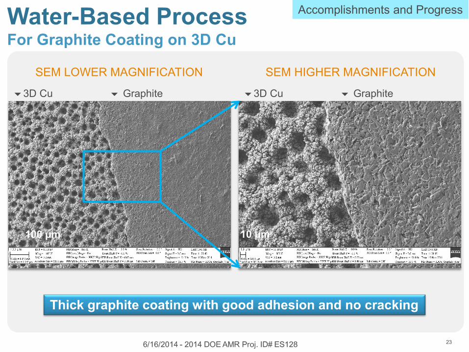
Water-Based Process For Graphite Coating on 3D Cu
3D Cu Graphite
Thick graphite coating with good adhesion and no cracking
SEM LOWER MAGNIFICATION SEM HIGHER MAGNIFICATION
100 µm 10 µm
Accomplishments and Progress
3D Cu Graphite

C-Rate Advantages 3D Cu/Graphite in Half Cell Tests at >3 mAh/cm2 Loadings
Charge capacity of control graphite and 3D Cu 60 µm / Graphite samples at different C-rates
Charge capacity of control graphite and 3D Cu 60 µm / Graphite samples at 2C rate (half cell)
24
Accomplishments and Progress
20-24% increase in capacity retention

SINGLE LAYER POUCH CELL SLP-5 WITH 60μm 3D Cu/GRAPHITE ANODE AND NMC CATHODE
3D Cu shows good cycle life in full cells
Accomplishments and Progress Results Baseline Cell Cycling Test
25

Transition from Baseline Electrode to Interim Alloy Electrodes
26
Parameters Baseline Interim-I Interim-II
Electrode 3DCu/graphite CuSn(Fe)/Graphite CuSn(Fe)/Graphite
Thickness (µm) 109 77 78
Electrode area
(cm2)
4.5 x 11 5x5 5x5
Estimated loading
(mAh/cm2)
3.0 3.0 3.0

27
Accomplishments and Progress Modeling Results Cell Level Design for Baseline and Interim Cells
Energy density up to 750 Wh/L by reducing Irreversible Capacity Loss
Project Target >500 Wh/L

“This material is based upon work supported by the Department of Energy under Award Number DE-EE0005455.”
DISCLAIMER: "This report was prepared as an account of work sponsored by an agency of the United States Government.
Neither the United States Government nor any agency thereof, nor any of their employees, makes any warranty, express or implied, or assumes any legal liability or responsibility for the accuracy, completeness, or usefulness of any information, apparatus, product, or process disclosed, or represents that its use would not infringe privately owned rights. Reference herein to any specific commercial product, process, or service by trade name, trademark, manufacturer, or otherwise does not necessarily constitute or imply its endorsement, recommendation, or favoring by the United States Government or any agency thereof. The views and opinions of authors expressed herein do not necessarily state or reflect those of the United States Government or any agency thereof."
INDEMNIFICATION:
“By submitting a presentation file to Alliance Technical Services, Inc. for use at the U.S. Department of Energy’s Hydrogen and Fuel Cells Program and Vehicle Technologies Program Annual Merit Review Meeting, and to be provided as hand-out materials, and posting on the DOE’s website, the presentation authors and the organizations they represent agree to defend, indemnify and hold harmless Alliance Technical Services, Inc., its officers, employees, consultants and subcontractors; the National Renewable Energy Laboratory; the Alliance for Sustainable Energy, LLC, Managing and Operating Contractor of the U.S. Department of Energy’s National Renewable Energy Laboratory; and the U.S. Department of Energy from and against any and all claims, losses, liabilities or expenses which may arise, in whole or in part, from the improper use, misuse, unauthorized use or disclosure, or misrepresentation of any intellectual property claimed by others. Such intellectual property includes copyrighted material, including documents, logos, photos, scripts, software, and videos or animations of any type; trademarks; service marks; and proprietary, or confidential information.”
28
Acknowledgment

29
6/16/2014 - 2014 DOE AMR Proj. ID# ES128