modular proximal tibia brochure 2012 proximal...modular proximal tibia 1.1 product overview the mets...
TRANSCRIPT

METSModularProximal Tibia
Surgical procedure

Surgical Procedure
Contents
1.0
2.0
3.0
Device information 4 1.1 Product overview 1.2 Indications 1.3 Absolute contra-indications 1.4 Relative contra-indications 1.5 Capabilities and restrictions of use
Operation instruction and guidelines 5 – 112.1 Recommendations for component selection 2.2 General points to note when using trial components 2.3 Recommendations for assembly of implant 2.4 Special instruments 2.5 Femoral cutting guide 2.6 Bone preparation 2.7 Femoral cutting guide and bone preparation
Rotating hinged proximal tibia 12 – 213.1 Components 3.2 Trial components 3.3 Tibial resection levels: rotating hinge proximal tibia 3.4 Tibial preparation 3.5 Short resections < 120mm 3.5.1 Trial assembly and insertion 3.5.2 Implant assembly and insertion 3.5.3 The proximal tibial component 3.6 Resections > 120mm 3.6.1 Trial assembly and insertion 3.6.2 Implant assembly and insertion 3.6.3 The proximal tibial component 3.7 Extensive resections > 165mm 3.7.1 Trial assembly and insertion 3.7.2 Implant assembly and insertion 3.7.3 The proximal tibial component
1

Surgical Procedure
Contents
4.0
6.0
5.0
Fixed hinged proximal tibia 22 – 314.1 Components 4.2 Trial components 4.3 Tibial resection levels: fixed hinge proximal tibia 4.4 Tibial preparation 4.5 Short resections < 75mm 4.5.1 Trial assembly and insertion 4.5.2 Implant assembly and insertion 4.5.2.1 The proximal tibial component 4.6 Resections > 75mm 4.6.1 Trial assembly and insertion 4.6.2 Implant assembly and insertion 4.6.2.1 The proximal tibial component 4.6.2.2 The femoral component 4.6.2.3 Femoral plateau plates 4.7 Extensive resections > 150mm 4.7.1 Trial assembly and insertion 4.7.2 Implant assembly and insertion 4.7.2.1 The proximal tibial component The femoral component 32 – 345.1 Femoral plateau plates 5.2 Insertion of the axle and circlip 5.2.1 Insertion 5.2.2 Use of circlip pliers 5.3 Disassembly
Parts and order references 35
2 – 3

Basic overview
– For femoral preparation, please refer to section 2.5, 2.6 and 2.7.
The METS proximal tibial system is available with the option of two different proximal tibial components:
– Rotating hinge configuration which is covered in Section 3.
– Fixed hinge configuration which is covered in Section 4.
Custom components are available to match the METS system for extreme tibial resections. Please contact Stanmore Implants for more details.
Modular Proximal TibiaBasic overview
A
B C
A
B
C

Modular Proximal Tibia
1.1 Product overview The METS proximal tibial replacement system is designed as a modular system that can be used to replace diseased or deficient bone in the proximal tibia. The system consists of a SMILES knee, a proximal tibial component, a range of shafts in 15mm increments to suit differing lengths of resection, a range of hydroxyapatite coated collars of different diameters to match the size of the resected bone and a range of cemented stems to fit the intramedullary canal. Individual components of the tibial shaft are connected using interlocking taper junctions allowing quick and easy assembly. The SMILES knee comes with the option of two different proximal tibial components; a rotating hinge and a fixed hinge, both suitable for primary and revision bone tumour cases and for revision total knee replacements where there is significant erosion of the proximal tibial bone. The fixed hinge is chosen for cases with significant loss of soft tissue function and where additional constraint is required. For very special cases, the METS modular system can be used in conjunction with custom-made components. For further details, please contact Stanmore Implants.
1.2 Indications – Primary bone tumour – Secondary tumour arising in bone – Non-neoplastic conditions affecting the
shafts of long bones – Failed joint replacements with significant
bone loss – Failed massive replacements.
1.3 Absolute contra-indications – Infection and sepsis.
1.4 Relative contra-indications – Inadequate or incomplete soft
tissue coverage – Uncooperative or unwilling patient or
patient unable to follow instructions – Foreign body sensitivity. Where materials
sensitivity occurs, seek advice with respect to testing
– Obesity – Vascular disorders, neuromuscular
disorders or muscular dystrophy – Inadequate bone stock.
1.5 Capabilities and restrictions of use – The components are designed and
manufactured and are to be assembled and used only in the manner specified. Any deviation from this may reduce the in-service life of the prosthesis.
– Mixing with unspecified components either from Stanmore Implants or from other manufacturers is not permitted since it may lead to mal-alignment, inadequate assembly, excessive wear and premature failure.
– A fully assembled proximal tibial replacement must consist of one of the two proximal tibia assemblies (rotating hinge or fixed hinge) with bumper, a femoral component with bushes, an axle and a circlip, a shaft with or without an extension piece, a collar, and a stem.
– The collar is not an optional item and it must be used. Failure to do so may result in excessive subsidence of the prosthesis.
– Should the interlocking surfaces of any of the implant components become damaged, they must not be used.
– The implant components are for SINGLE USE only and they must not be re-used.
– A set of instruments is provided to assist assembly of prosthesis, which includes a set of metal and Radel R trial components. The trial components are coloured to easily distinguish from implant components. Rotating hinge trials are blue, fixed hinge trials are yellow and all other trial components that can be used with both hinged versions are coloured green. Trial femoral plateau plates are titanium and anodised blue, while trial femoral components are silver and blue.
– In addition, the trial components cannot be used in combination with implant components.
– This implant is produced from titanium and CoCrMo alloys and therefore under no circumstances must it be allowed to come in contact with another stainless steel device since this would induce galvanic corrosion.
1.0 Device description
4 – 5

Modular Proximal Tibia2.0 Operation instructions and guidelines
2.1 Recommendations for component selection
Size of femoral knee component Where possible, a standard sized knee component should be used if the bone and surrounding soft tissues can accommodate it. For smaller patients, a small sized femoral knee can be used.
Tibial components Ideally, a rotating hinge proximal tibial replacement is recommended for cases where there is good muscle function and stability of the joint. Fixed hinged proximal tibial replacements should be considered where there is marked instability of the joint and the soft tissues have been sacrificed.
Shaft The prosthetic construct should only have one principal shaft with an extension shaft if required. More than one principal shaft must not be used.
Stem In order to optimise the implant fixation and strength, it is recommended that the largest stem diameter be chosen whilst still maintaining a minimum of 1mm cement mantle. Where thicker cortex is present, consider reaming the canal to accommodate the largest possible stem.
2.2 General points to note when using trial components – Trial shafts and stems are assembled
with a “push and click” mechanism where the rotational orientation is controlled by a lug.
– The trial collars are relieved by 2mm in the anterior/medial and anterior/lateral aspect and simply slide over the shaft. They can be used for left and right implants and are held in position by the insertion of a stem.
– There is a single sized axle for the trial components, thus it can be used for both small and standard size knees. The axle can be inserted from either side. It should be noted that a circlip is not required for the trial components.
– The trial components are designed to give a representation of the physical size of the actual implant component, and therefore, during trial reduction, they should provide an indication of the degree of soft tissue coverage and the function of the device.
– The trial proximal tibial components represent only the size and shape of the actual tibial construct and therefore do not rotate.
– During removal of the trial implant, if the stem should become lodged in the canal and left behind, use trial stem extractor to remove it.
2.3 Recommendations for assembly of implant It is recommended that the following points be considered during assembly of an implant:
– Always fully assemble an implant before exposing it to the body’s environment; failure to do so may result in contaminating the interlocking mechanism, which can impair the performance of the implant.
– Impact each junction as described in sections 3.5.2 or 4.5.2 in order to provide optimum strength to the joint. This is important since each interface will experience large bending forces that can result in excessive wear and fretting if not correctly assembled.
– Care must also be exercised when assembling components with hydroxyapatite coating, as it is brittle and can easily be damaged.
A
A

Modular Proximal Tibia
2.4 Special Instruments
1 Bush compressor standard2 Bush compressor small3 Bush reamer standard4 Bush reamer small5 Distraction tool6 Collar impacter small7 Drill Ø10mm8 Drill Ø8mm9 Stem extractor10 Bush compressor nut 11 Circlip pliers12 Femoral cutting block standard13 Pliers14 Femoral cutting block small
15 Hammer16 Distal cutting guide plate17 Distal cutting guide bolt screw18 Distal cutting IM rod19 Drill guide20 Collar impactor integral21 General impactor22 Plastic bearing impactor small23 Plastic bearing impactor standard
2.0 Operation instructions and guidelines
7
6
8
9
11 12
13
14
15
16
17
18
1920
21
22
23
10
5
1
2
3
4
6 – 7

Modular Proximal Tibia2.0 Operation instructions and guidelines
2.5 Femoral cutting guide In addition to these instruments, it is anticipated that the operating theatre should make available a bone saw, flexible reamers and an appropriate cement application device.
Ø10mm drill
Distal cutting guide bolt
Ø8mm drill
Distal cutting guide plate
Distal cutting guide slider
Distal cutting IM rodDistal cutting guide
Standard femoral cutting block
Small femoral cutting block
Drill guide

2.6 Bone preparation It should be noted that there is no prescribed order as to which bone (the femur or the tibia) is prepared first. Before femoral preparation, the size of the SMILES knee must be chosen as appropriate for the patient’s knee.
2.7 Femoral cutting guide and bone preparation
– Rotate the patella rest on the drill guide until the correct size SMILES knee mark is aligned with the arrow on the top of the guide.
– Place the drill guide on the condyles of the femur.
– With the patella rest resting in the patella track of the bone, rotate the drill guide in the sagittal plane and about the long axis of the bone so that the posterior condyles are aligned with the back edge of drill guide and that the patella rest is approximately in line with the femoral canal.
– Tap the drill guide using the hammer provided so the spikes are embedded into the condyles.
– Using the Ø10mm drill, drill through the guide into the inter-condylar notch to the depth indicated by the stop located on the drill.
– Remove the guide.
– Using Ø8mm drill, deepen the hole ensuring the drill follows the intramedullary canal of the femur to the depth marked on the drill.
Modular Proximal Tibia2.0 Operation instructions and guidelines
A
A
B
D
E
C
B
C
D
E
8 – 9
Patella rest
Drill guide Ø10mm drill

– Insert the IM rod into the distal cutting guide for right or left femur – as required – and lock it in position using the locking screw located in front of the distal cutting guide. The relevant marking should be proximal when inserting the rod into the guide.
– Assemble the distal cutting guide, guide slider, distal cutting guide slider bolt and the distal cutting plate. According to the chart below, adjust the guide slider for the amount of femoral resection measured from the femoral condyles and secure it by tightening the locking screw positioned above it.
Modular Proximal Tibia2.0 Operation instructions and guidelines
Size of SMILES Knee Slider readingSmall 22mmStandard 24mm
F
G
F
Distal cutting guide
IM rod
Locking screw
Femoral cutting guide assembled correctly
G
Guide slider
Distal cutting plate
Distal cutting guide slider bolt

Modular Proximal Tibia2.0 Operation instructions and guidelines
– Insert the IM rod into the previously drilled hole in the femur. Push the rod in as far as it can go, ensure that at least one of the femoral condyles is making contact with the distal cutting guide and then rotate the guide along the long axis of the femur to align with posterior condyles with the back edge of the cutting guide. Impact the three pins housed in the cutting plate to secure it onto the femoral bone.
HH
10 – 11
Modular Proximal Tibia2.0 Operation instructions and guidelines
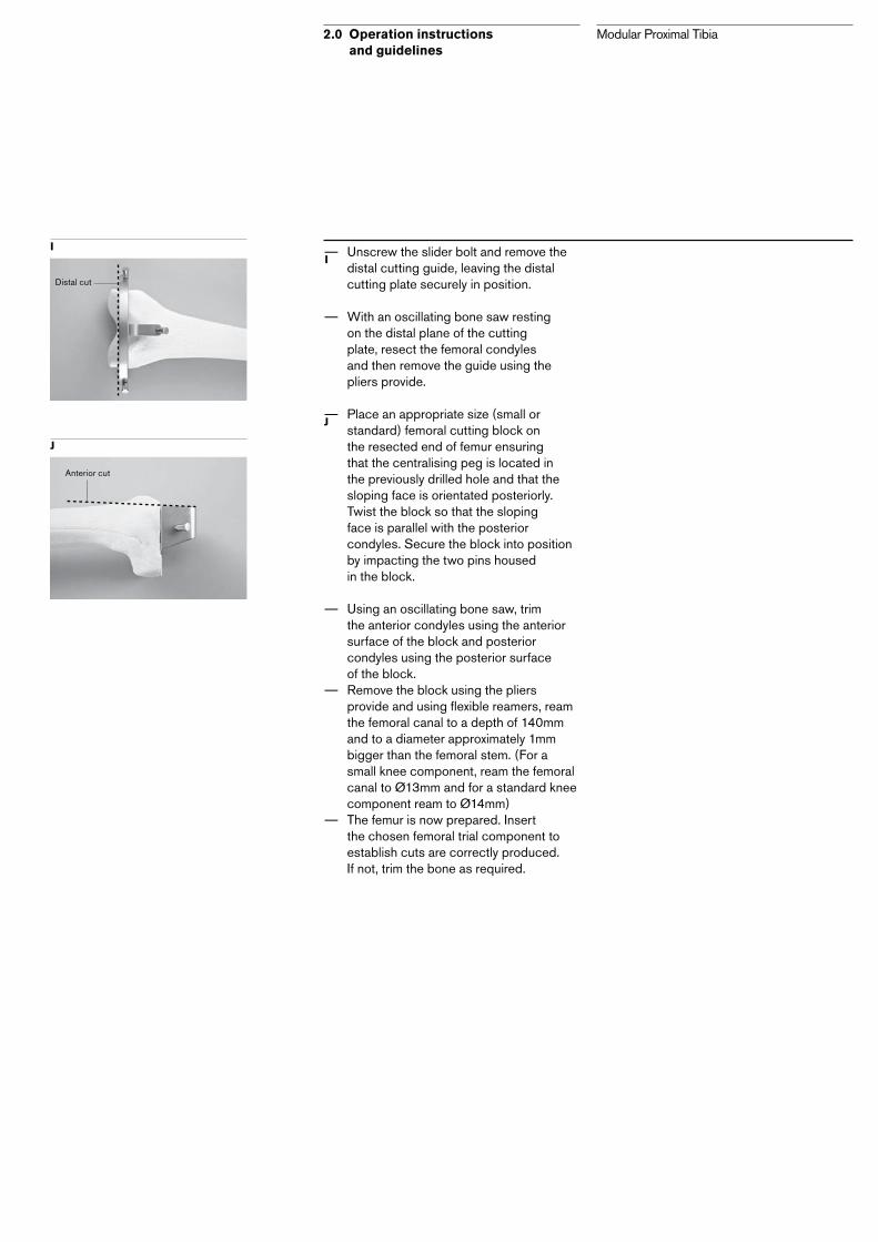
– Unscrew the slider bolt and remove the distal cutting guide, leaving the distal cutting plate securely in position.
– With an oscillating bone saw resting on the distal plane of the cutting plate, resect the femoral condyles and then remove the guide using the pliers provide.
– Place an appropriate size (small or standard) femoral cutting block on the resected end of femur ensuring that the centralising peg is located in the previously drilled hole and that the sloping face is orientated posteriorly.Twist the block so that the sloping face is parallel with the posterior condyles. Secure the block into position by impacting the two pins housed in the block.
– Using an oscillating bone saw, trim the anterior condyles using the anterior surface of the block and posterior condyles using the posterior surface of the block.
– Remove the block using the pliers provide and using flexible reamers, ream the femoral canal to a depth of 140mm and to a diameter approximately 1mm bigger than the femoral stem. (For a small knee component, ream the femoral canal to Ø13mm and for a standard knee component ream to Ø14mm)
– The femur is now prepared. Insert the chosen femoral trial component to establish cuts are correctly produced. If not, trim the bone as required.
I
J
I
Distal cut
J
Anterior cut

Modular Proximal Tibia3.0 Rotating hinged proximal tibia
12 – 13
1
2
3 6 8
4 4
4
9
5
7
7
1 Rotating hinge tibial component small and standard2 Rotating hinge proximal tibial component small and standard3 Integral collar/shaft/stem x1 (HA coated)4 HA collars x5 sizes5 Integral shaft/stem x16 Rotating hinge prinicpal shafts x3 lengths7 IM stems x5 diameters8 Rotating hinge extension shafts x1 length9 Fixed hinge principal shafts x5 lengths

Modular Proximal Tibia3.0 Rotating hinged proximal tibia
3.1 Components of the rotating hinged proximal tibial implant
Femoral plateau platesOptional femoral plateau plates (not shown) are available in 5, 10, 15 and 20mm thicknesses for both small and standard sizes.
Rotating hinge proximal tibial componentA titanium proximal tibial component with UHMWPE tibial bearing and a CoCrMo tibial component. In small and standard sizes, with HA coated patella tendon reattachment mechanism or smooth uncoated. Packaged as two individual assemblies:
– Rotating hinge proximal tibial component and UHMWPE bearing.
– Rotating hinge CoCrMo tibial component and UHMWPE bumper pad.
Shaft85 to 115mm long titanium shafts in 15mm increments.
– A 85mm long extension shaft to further increase the length capability.
– For very short resections, integral shafts / stems are
available in two lengths 55mm and 70mm.
Total length capability gives a range from 105mm to 240mm from tibial condyles to tibial plateau.
Cemented stemØ9 to Ø13mm straight titanium stems in 1mm increments and 120mm long. For extreme resections, a custom-made stem can be manufactured for use with this system. Please contact Stanmore Implants.
Axle, bushes and circlipA cobalt-chromium-molybdenum axle, a pair of UHMWPE bushes and a titanium circlip. (Packaged with the femoral component).
BumperAn UHMWPE bumper providing a secondary bearing surface and a soft hyperextension stop.
CollarØ20, Ø23, Ø26, Ø29 and Ø32mm HA coated titanium collars.
Femoral componentCobalt-chromium-molybdenum femoral component with a titanium stem. Anatomical for left and right sides. Available in small and standard sizes, with 140mm long femoral curved stem Ø13mm for standard components and Ø12mm for small components.

3.2 Trial components of the rotating hinged proximal tibia
Modular Proximal Tibia3.0 Rotating hinged proximal tibia
Femoral plateau platesTrial femoral plateau plates (not shown) in 5, 10, 15 and 20mm thicknesses for both small and standard sizes.
Trial rotating hinge proximal tibial component Trial proximal tibial component in small and standard sizes.
Trial axleOne size axle that can fit both small and standard components and can be inserted from either side of the knee.
Trial stemØ9 to Ø13mm straight stems in 1mm increments, 120mm long.
Trial collarsØ20mm to Ø32mm trial collars.
Trial shaft85 to 115mm trial shafts in 15mm increments with an 85mm long trial extension shaft and 55 and 70mm long trial integral shaft/stem constructs.
Trial femoral componentSmall and standard sizes in left hand and right hand versions.
14 – 15

Modular Proximal Tibia3.0 Rotating hinged proximal tibia
3.3 Tibia resection levels: Rotating hinge proximal tibiaPlease note: For extreme resections where a 120mm long stem is unsuitable, a stem made to your requirements may be custom manufactured. Please contact Stanmore Implants. It should be noted collar lengths are included in the resection values.
Tibial component plateau
Integral shaft/stem 55mm
Integral shaft/stem 70mm
Rotating hinge principal shaft 85mm
Rotating hinge principal shaft 100mm
Rotating hinge principal shaft 115mm
Rotating hinge extension shaft (85mm) + fixed hinge principal shaft 45mm
Rotating hinge extension shaft (85mm) + fixed hinge principal shaft 60mm
Rotating hinge extension shaft (85mm) + fixed hinge principal shaft 75mm
Rotating hinge extension shaft (85mm) + fixed hinge principal shaft 90mm
Rotating hinge extension shaft (85mm) + fixed hinge principal shaft 105mm
Shaft Component Resections
50mm
105mm
120mm
135mm
150mm
165mm
180mm
195mm
210mm
225mm
240mm
Medial tibial condyle

3.4 Tibial preparation – Resect the tibial bone to the level required. – Further trimming may be required when
selecting the trial components. Please refer to section 3.3 as a guide.
– Ream the tibial canal using an appropriate sized flexible reamer to a depth of 120mm and to the required diameter to accommodate the tibial stem, leaving a minimum of 1mm for the cement mantle.
3.5 Short resections < 120mm – For resections that are shorter than the
smallest principal shaft, integral shaft/stem constructs can be used.
– Integral shaft/stem components for the rotating hinged proximal tibial replacement are available in two shaft lengths 55mm and 70mm with a 120mm straight tibial stem Ø10mm.
– The 55mm integral shaft/stem construct has a fixed collar diameter of 26mm and is available hydroxyapatite coated.
– The 70mm integral shaft/stem construct must be used with any of the hydroxyapatite coated collars.
3.5.1 Trial assembly and insertion – Select the required size and side of the
trial femoral component and insert into the prepared femur.
– Select appropriate size proximal tibial component and integral shaft/stem construct to replace the resected length of the tibia and assemble them as described in the section 2.2. The assembly sequence should be tibial component onto the shaft/stem construct followed by the collar if using the 70mm integral construct.
– Insert the tibial assembly into the tibia. – Join the femoral and tibial components
together by insertion of the trial axle ensuring that it is correctly seated before performing a trial reduction.
– Once satisfied, remove all trial components and select corresponding implant components.
– During removal of the trial implant, if the stem should become lodged within the canal and left behind, the trial stem extractor should be used to remove it as shown on Page 5.
– If the joint is too tight or too loose between shaft increments, it may be necessary to resect extra bone from the tibia and repeat the trial.
Modular Proximal Tibia3.0 Rotating hinged proximal tibia
A
A
B
16 – 17
B

Modular Proximal Tibia3.0 Rotating hinged proximal tibia
3.5.2 Implant assembly and insertion
3.5.3 The proximal tibial component
– Holding the proximal tibial component with the spigot pointing upwards, insert the integral shaft/stem construct ensuring that the alignment lug is correctly engaged. Apply multiple sharp blows using the soft ended hammer provided to lock the taper securely in place.
70mm integral shaft/stem construct only
– If the collar is to be assembled separately, slide the selected collar over the stem of the assembled integral shaft/stem construct ensuring the alignments lugs are correctly engaged and the correct orientation is achieved.
– Place the integral collar impactor over the stem and using the soft ended hammer, apply multiple sharp blows to lock the components together, taking care not to damage the hydroxyapatite coating.
The proximal tibial component is now assembled and ready for insertion.
– Insert the proximal tibial component into the tibial canal and cement it securely into place using the polyethylene bearing impactor and the soft ended hammer provided, ensuring correct rotational alignment.
– Insert the rotating hinge tibial component into the rotating hinge proximal tibial component.
– Proceed to section 5.0
A
A
C
C
B
B
Integral shaft/stem (70mm shaft)
Integral collar impact
Hydroxyapatite coated collar
Rotating hinge proximal tibial component

3.6 Resections > 120mm
3.6.1 Trial assembly and insertion – Select the required size and side of the
trial femoral component and insert into the prepared femur.
– Select appropriate size proximal tibial component, shaft, collar and stem to replace the resected length of the tibia and assemble them as described in section 2.2. The assembly sequence should be tibial component onto the shaft followed by collar and then stem respectively.
– Insert the tibial assembly into the tibia. – Join the femoral and tibial components
together by insertion of the trial axle ensuring that it is correctly seated before performing a trial reduction. Replace shaft/stem/collar as required until satisfactory assembly is produced.
– Once satisfied, remove all trial components and select corresponding implant components.
– During removal of the trial implant, if the stem should become lodged within the canal and left behind, the trial stem extractor should be used to remove it as shown on Page 5.
– If the joint is too tight or too loose between shaft increments, it may be necessary to resect extra bone from the tibia and repeat the trial.
Modular Proximal Tibia3.0 Rotating hinged proximal tibia
18 – 19

Modular Proximal Tibia3.0 Rotating hinged proximal tibia
3.6.2 Implant assembly and insertion
3.6.3 The proximal tibial component
– Place the proximal tibial component with the spigot pointing upwards; insert the principal shaft ensuring that the alignment lug is properly engaged. Place the collar impactor over into the bore on the shaft and apply multiple sharp blows using the soft hammer provided, locking the taper securely in place.
– Place the selected collar onto the distal end of the shaft ensuring once again the alignment lugs are correctly aligned. Holding the collar impactor over the collar, impact using multiple sharp hammer blows as shown opposite, taking care not to damage the bore or hydroxyapatite coating.
– Finally, insert the appropriate sized stem, ensuring the alignment lug is correctly located and impact using multiple sharp blows on the end of the stem.
– The proximal tibial component is now assembled and ready for insertion.
– Insert the proximal tibial component into the tibial canal and cement securely into place ensuring correct rotational alignment. Impact the stem using the polyethylene bearing impactor and soft ended hammer provided.
– Insert the rotating hinge tibial component into the rotating hinge proximal tibial component.
– Proceed to Section 5.0
A
A
B
C
B
C

3.7 Extensive resections > 165mm
– For resections greater than 165mm, the use of an extension shaft is required. The rotating hinged extension shaft is 85mm long and must be used with the fixed hinge principal shafts.
3.7.1 Trial assembly and insertion – Select the required size and side of the
trial femoral component and insert into the prepared femur.
– Select appropriate size proximal tibial component, extension shaft, fixed hinge principal shaft, collar and stem to replace the resected length of the tibia and assemble them as described in the sections 2.2. The assembly sequence should be tibial component onto extension shaft, then the fixed hinge principal shaft followed by collar and then stem respectively. Insert the tibial assembly into the tibia.
– Join the femoral and tibial components together by insertion of the trial axle ensuring that it is correctly seated before performing a trial reduction. Replace shaft/stem/collar as required until satisfactory assembly is produced.
– Once satisfied, remove all trial components and select corresponding implant components.
– During removal of the trial implant, if the stem should become lodged within the canal and left behind, the trial stem extractor should be used to remove it as shown on Page 5.
– If the joint is too tight or too loose between shaft increments, it may be necessary to resect extra bone from the tibia and repeat the trial.
Modular Proximal Tibia3.0 Rotating hinged proximal tibia
20 – 21
A
A
3.7.2 Implant assembly and insertion
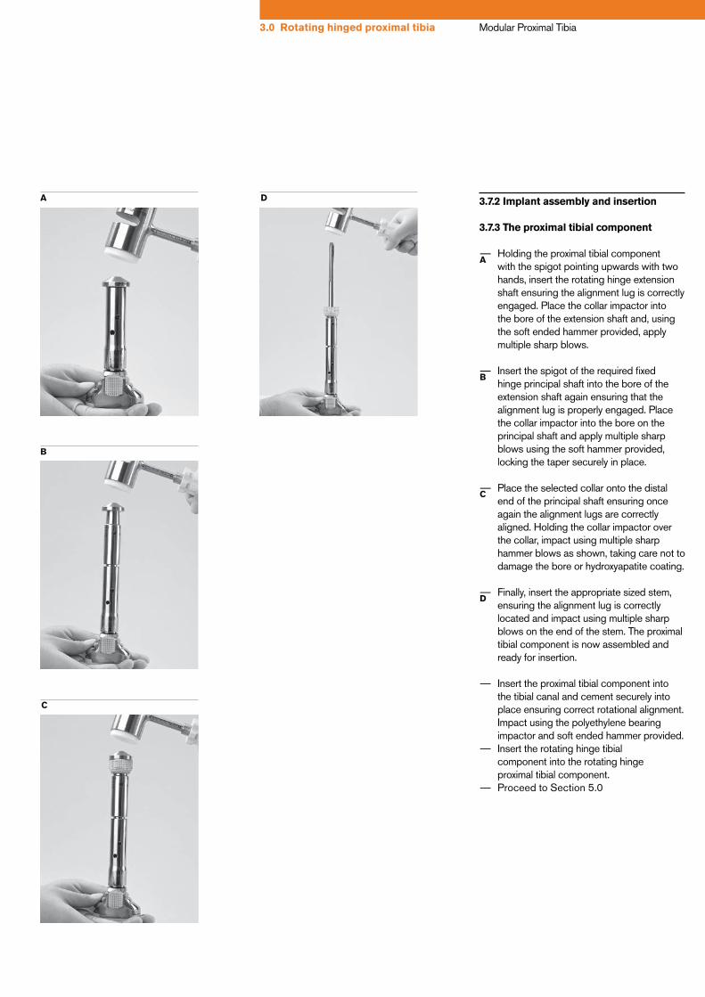
3.7.3 The proximal tibial component
– Holding the proximal tibial component with the spigot pointing upwards with two hands, insert the rotating hinge extension shaft ensuring the alignment lug is correctly engaged. Place the collar impactor into the bore of the extension shaft and, using the soft ended hammer provided, apply multiple sharp blows.
– Insert the spigot of the required fixed hinge principal shaft into the bore of the extension shaft again ensuring that the alignment lug is properly engaged. Place the collar impactor into the bore on the principal shaft and apply multiple sharp blows using the soft hammer provided, locking the taper securely in place.
– Place the selected collar onto the distal end of the principal shaft ensuring once again the alignment lugs are correctly aligned. Holding the collar impactor over the collar, impact using multiple sharp hammer blows as shown, taking care not to damage the bore or hydroxyapatite coating.
– Finally, insert the appropriate sized stem, ensuring the alignment lug is correctly located and impact using multiple sharp blows on the end of the stem. The proximal tibial component is now assembled and ready for insertion.
– Insert the proximal tibial component into the tibial canal and cement securely into place ensuring correct rotational alignment. Impact using the polyethylene bearing impactor and soft ended hammer provided.
– Insert the rotating hinge tibial component into the rotating hinge proximal tibial component.
– Proceed to Section 5.0
A
B
C
D
Modular Proximal Tibia3.0 Rotating hinged proximal tibia
A
C
B
D

Modular Proximal Tibia4.0 Fixed hinge proximal tibia
22 – 23
1
2 4 5
5
7
3 3
3
6
6
1 Fixed hinge proximal tibial small and standard2 Integral collar/shaft/stem x1 (HA coated)3 HA collars x5 sizes4 Integral shaft/stem x15 Fixed hinge principal shafts x5 shafts6 IM stems x5 diameters7 Fixed hinge extension shafts x1

4.1 Components of the fixed hinged proximal tibial implant
Modular Proximal Tibia4.0 Fixed hinge proximal tibia
Femoral componentCobalt-chromium-molybdenum femoral component with a titanium stem. Anatomical for left and right sides. Available in small and standard sizes, with 140mm long femoral curved stem Ø13mm for standard components and Ø12mm for small components.
Femoral plateau platesOptional femoral plateau plates (not shown) are available in 5, 10, 15 and 20mm thicknesses for both small and standard sizes.
Axle, bushes and circlipA cobalt-chromium-molybdenum axle, a pair of UHMWPE bushes and a titanium circlip. (Packaged with femoral components)
BumperAn UHMWPE bumper providing a secondary bearing surface and a soft hyperextension stop. Pre-assembled with the proximal tibial component.
Fixed hinged proximal tibial componentA CoCrMo proximal tibial component. In small and standard sizes with HA coated patella tendon reattachment mechanism or smooth uncoated.
Shaft45 to 105mm long titanium shafts in 15mm increments.
– A 75mm extension shaft to further increase the length capability.
– For very small resections, integral shafts/stems are available in two lengths 15mm and 30mm.
It must be noted that a HA coated collar must be used. Total length capability gives a range from 60mm to 225mm from tibial condyles to tibial plateau.
Cemented stemØ9 to Ø13mm straight titanium stems in 1mm increments and 120mm length. For extreme resections, a custom-made stem can be manufactured for use with this system. Please contact the Stanmore Implants.
CollarØ20, Ø23, Ø26, Ø29 and Ø32mm HA coated titanium collars.

4.2 Trial components of the fixed hinged proximal tibia
Modular Proximal Tibia4.0 Fixed hinge proximal tibia
Femoral plateau platesTrial femoral plateau plates (not shown) in 5, 10, 15 and 20mm thicknesses for both small and standard sizes.
24 – 25
Trial axleOne size axle that can fit both small and standard components and can be inserted from either side of the knee.
Trial femoral componentSmall and standard sizes in left hand and right hand versions.
Trial fixed hinged proximaltibial componentTrial proximal tibial component. In small and standard sizes.
Trial collarØ20mm to Ø32mm trial collars.
Trial shaft45 to 105mm trial shafts in 15mm increments with a 75mm long trial extension shaft and 15 and 30mm long trial integral shaft/stem constructs.
Trial stemØ9 to Ø13mm straight stems in 1mm increments, 120mm long.
Modular Proximal Tibia4.0 Fixed hinge proximal tibia
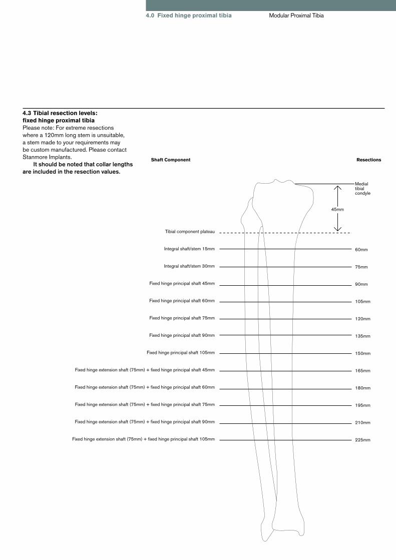
4.3 Tibial resection levels: fixed hinge proximal tibiaPlease note: For extreme resections where a 120mm long stem is unsuitable, a stem made to your requirements may be custom manufactured. Please contact Stanmore Implants. It should be noted that collar lengths are included in the resection values.
Tibial component plateau
Integral shaft/stem 15mm
Integral shaft/stem 30mm
Fixed hinge principal shaft 45mm
Fixed hinge principal shaft 60mm
Fixed hinge principal shaft 75mm
Fixed hinge principal shaft 90mm
Fixed hinge principal shaft 105mm
Fixed hinge extension shaft (75mm) + fixed hinge principal shaft 45mm
Fixed hinge extension shaft (75mm) + fixed hinge principal shaft 60mm
Fixed hinge extension shaft (75mm) + fixed hinge principal shaft 75mm
Fixed hinge extension shaft (75mm) + fixed hinge principal shaft 90mm
Fixed hinge extension shaft (75mm) + fixed hinge principal shaft 105mm
Shaft Component Resections
45mm
60mm
75mm
90mm
105mm
120mm
135mm
150mm
165mm
180mm
195mm
210mm
225mm
Medial tibial condyle

4.4 Tibial preparation – Resect the tibial bone to the level required.– Further trimming may be required when
selecting the trial components. Please refer to section 4.3 as a guide.
– Ream the tibial canal using an appropriate sized flexible reamer to a depth of 120mm and to the required diameter to accommodate the tibial stem, leaving a minimum of 1mm for the cement mantle.
4.5 Short resections < 75mm – For resections that are shorter than the
smallest principal shaft, integral shaft/stem constructs can be used. Integral shaft/stem components for the fixed hinged proximal tibial replacement are available in two shaft lengths 15mm and 30mm with a 120mm straight tibial stem Ø12mm.
– The 15mm integral shaft/stem construct has a fixed collar diameter of 33mm and is hydroxyapatite coated.
– The 30mm integral shaft/stem construct allows you the option to use any of the hydroxyapatite coated collars.
4.5.1 Trial assembly and insertion – Select the required size and side of trial
femoral component and insert into the prepared femur.
– Select appropriate size proximal tibial component and integral shaft/stem construct to replace the resected length of the tibia and assemble them as described in section 2.2. The assembly sequence should be tibial component onto the shaft stem/stem construct followed by the collar if using the 30mm integral construct. Insert the tibial assembly into the tibia.
– Join the two components together by insertion of the trial axle ensuring that it is correctly seated before performing a trial reduction. Replace shaft/stem/collar as required until satisfactory assembly is produced.
– Once satisfied, remove all trial components and select corresponding implant components.
– During removal of the trial implant, if the stem should become lodged within the canal and left behind, the trial stem extractor should be used to remove it as shown on Page 5.
– If the joint is too tight or too loose between shaft increments, it may be necessary to resect extra bone from the tibia and repeat the trial.
Modular Proximal Tibia4.0 Fixed hinge proximal tibia
A
A
B
26 – 27
B

Modular Proximal Tibia4.0 Fixed hinge proximal tibia
4.5.2 Implant assembly and insertion
4.5.2.1 The proximal tibial component – Holding the proximal tibial component
with the bore pointing upwards, insert the integral shaft/stem construct ensuring that the alignment lug is correctly engaged. Apply multiple sharp blows using the soft ended hammer provided to lock the taper securely in place.
30mm integral shaft stem construct only
– If the collar is to be assembled separately, slide the selected collar over the stem of the assembled integral shaft/stem construct ensuring the alignments lugs are correctly engaged and the correct orientation is achieved.
– Place the integral collar impactor over the stem and using the soft ended hammer, apply multiple sharp blows to lock the components together, taking care not to damage the hydroxyapatite coating.
The proximal tibial component is now assembled and ready for insertion.
– Using the general impactor and soft ended hammer provided, insert the proximal tibial component into the tibial canal and cement securely into place, ensuring correct rotational alignment.
– Proceed to section 5.0
A
B
C
A C
B
Integral shaft/stem (30mm shaft)
Integral collar impact
Hydroxyapatite coated collar
Fixed hinge proximal tibial component

4.6 Resections > 75mm
4.6.1 Trial assembly and insertion – Select the required size and side of trial
femoral component and insert into the prepared femur.
– Select appropriate size proximal tibial component, shaft, collar and stem to replace the resected length of the tibia and assemble them as described in section 2.2. The assembly sequence should be tibial component onto the shaft followed by the collar and then the stem respectively.
– Insert the tibial assembly into the tibia. – Join the two components together by
insertion of the trial axle ensuring that it is correctly seated before performing a trial reduction. Replace shaft/stem/collar as required until satisfactory assembly is produced.
– Once satisfied, remove all trial components and select corresponding implant components.
– During removal of the trial implant, if the stem should become lodged within the canal and left behind, the trial stem extractor should be used to remove it as shown on Page 5.
– If the joint is too tight or too loose between shaft increments, it may be necessary to resect extra bone from the tibia and repeat the trial.
Modular Proximal Tibia4.0 Fixed hinge proximal tibia
28 – 29

Modular Proximal Tibia4.0 Fixed hinge proximal tibia
4.6.2 Implant assembly and insertion
4.6.2.1 The proximal tibial component
– Hold the proximal tibial component with the bore pointing upwards with two hands. Insert the spigot of the required principal shaft ensuring that the alignment lug is properly engaged. Place the collar impactor into the bore on the shaft and apply multiple sharp blows using the soft hammer provided, locking the taper securely in place.
– Place the selected collar onto the distal end of the shaft ensuring once again the alignment lugs are correctly aligned. Holding the collar impactor over the collar, impact using multiple sharp hammer blows as shown below taking care not to damage the bore or hydroxyapatite coating.
– Finally, insert the appropriate sized stem, ensuring the alignment lug is correctly located and impact with multiple sharp blows on the end of the stem.
– The proximal tibial component is now assembled and ready for insertion. – Using the general impactor and soft ended
hammer provided, insert the proximal tibial component into the tibial canal and cement securely into place, ensuring correct rotational alignment.
– Proceed to section 5.0
A
B
C
A
B
C

4.7 Extensive resections > 120mm
– For resection greater than 120mm, the use of an extension shaft is required. The extension shaft is 75mm long and must be used with a principal shaft.
4.7.1 Trial assembly and insertion – Select the required size and side of trial
femoral component and insert into the prepared femur.
– Select appropriate size proximal tibial component, extension shaft, principal shaft, collar and stem to replace the resected length of the tibia and assemble them as described in the section 2.2. The assembly sequence should be tibial component onto the extension shaft, then the principal shaft followed by the collar and then the stem respectively. Insert the tibial assembly into the tibia.
– Join the two components together by insertion of the trial axle ensuring that it is correctly seated before performing a trial reduction. Replace shaft/stem/collar as required until satisfactory assembly is produced.
– Once satisfied, remove all trial components and select corresponding implant components.
– During removal of the trial implant, if the stem should become lodged within the canal and left behind, the trial stem extractor should be used to remove it as shown on Page 5.
– If the joint is too tight or too loose between shaft increments, it may be necessary to resect extra bone from the tibia and repeat the trial.
Modular Proximal Tibia4.0 Fixed hinge proximal tibia
30 – 31
A
A

Modular Proximal Tibia4.0 Fixed hinge proximal tibia
4.7.2 Implant assembly and insertion
4.7.2.1 The proximal tibial component
– Holding the proximal tibial component with the bore pointing upwards with two hands, insert the spigot of the fixed hinge extension shaft ensuring the alignment lug is correctly engaged. Place the collar impactor over the bore of the extension shaft and, using the soft ended hammer provided, apply multiple sharp blows.
– Insert the spigot of the required fixed hinge principal shaft into the bore of the extension shaft again ensuring that the alignment lug is properly engaged. Place the collar impactor into the bore on the principal shaft and apply multiple sharp blows using the soft hammer provided, locking the taper securely in place.
– Place the selected collar onto the distal end of the shaft ensuring once again the alignment lugs are correctly aligned. Holding the collar impactor over the collar, impact using multiple sharp hammer blows as shown taking care not to damage the bore or hydroxyapatite coating.
– Finally, insert the appropriate sized stem, ensuring the alignment lug is correctly located and impact using multiple sharp blows on the end of the stem.
– The proximal tibial component is now assembled and ready for insertion.
– Using the general impactor and soft ended hammer provided, insert the proximal tibial component into the tibial canal and cement securely into place, ensuring correct rotational alignment.
– Proceed to section 5.0
A
B
C
D
A
C
B
D

5.0 The femoral component – Cement the required femoral component
into the femoral canal, ensuring the correct orientation is achieved.
– Impact using the general impactor.
5.1 Femoral plateau plates – Optional femoral plateau plates
are available in 5, 10 15 and 20mm thicknesses for both small and standard sizes.
– Using a small amount of bone cement, secure the plateau plate onto the femoral component by sliding it over the femoral stem until the anti-rotation lugs on the femoral component are located within the holes in the femoral plateau plate.
It should be noted that only one femoral plateau plate can be used. Multiple plates cannot be stacked onto one another.
5.2 Insertion of the axle and circlip
5.2.1 Insertion of axle
– Align the femoral and tibial components and insert the axle into position as shown. It should be noted that the axle can be inserted from either side of the knee joint.
– Using the pronged end of the circlip pliers handle, push the axle in place. If required, rotate the axle to engage the axle head into the offset recess in the femoral component.
– Check to ensure the axle head is correctly sitting inside the recess and that it is not trapped within the circlip groove.
Modular Proximal Tibia5.0 The femoral component
B
C
32 – 33
A
B
C
A

Modular Proximal Tibia5.0 The femoral component
5.2.2 Use of circlip pliers
– The circlip and the pliers are designed to clip together for ease of use. The best way to place the circlip onto the pliers is by holding the circlip on your finger tip and then pushing the pliers into it ensuring the central pin locates in the centre of the circlip and the two moving jaws are either side of the central strips of the circlip as shown in the pictures below.
– A correctly inserted circlip is shown on the left with the jaws of the circlip pliers in the correct position.
– This picture on the left shows an incorrectly inserted circlip. This would not function and the circlip needs reinserting.
(Requires rotating 180º)
– The circlip is best inserted into the knee by holding the circlip at an angle, then placing the circular part of the circlip into the groove in the tibial component and then straightening and pushing the circlip into position as shown.
– Release circlip pliers and pull to unclip from the circlip.
– Ensure that the circlip is seated inside the groove in the tibial component and then, using a pointed implement, rotate it to ensure it turns inside the groove. Rotation of the circlip ensures the circlip is fully engaged in the groove.
A
A
B
C
D
E
D
B – Correct E
C – Incorrect

5.3 Disassembly
– During revision surgery, it may be necessary to disassemble the implant. This is achieved by inserting the distraction tool into the anterior hole of the shaft and impacting with a hammer.
– The distraction tool has a flat, which should locate on the end of the inner spigot. Part are for SINGLE USE only and cannot be reused.
A
A
34 – 35
Modular Proximal Tibia5.0 The femoral component

Modular Proximal Tibia6.0 Parts and order references
Femoral knee Components Small Left mptfc/LSm Small Right mptfc/RSm Standard Left mptfc/LStd Standard Right mptfc/RStd Proximal tibia Fixed hinge Small mptfh/SmU Plain uncoated Standard mptfh/StdU Fixed hinge Small mptfh/SmC With reattachment HA coated Standard mptfh/StdC Rotating hinge Small mptrh/SmU Plain uncoated Standard mptrh/StdU Rotating hinge Small mptrh/SmC With reattachment HA coated Standard mptrh/StdC Tibial components Rotating hinge Small mktsc/Sm Standard mktsc/Std Tibial shafts Fixed hinge 45mm mptfhshft/45 60mm mptfhshft/60 75mm mptfhshft/75 90mm mptfhshft/90 105mm mptfhshft/105 Tibial extension shaft Fixed hinge 75mm mptfhext/75 Integral shafts & stems Shaft Stem Fixed hinge L = 15 D = 33 L = 120 D = 12 > 9 mptfhiss/15C L = 30 D = 33 L = 120 D = 12 > 9 mptfhiss/30N Tibial shafts Rotating hinge 85mm mptrhshft/85 100mm mptrhshft/100 115mm mptrhshft/115 Tibial extension shaft Rotating hinge 85mm mptrhext/85 Integral shafts & stems Shaft Stem Rotating hinge L = 55 D = 26 L = 120 D = 10 > 9.5 mptrhiss/55C L = 70 D = 26 L = 120 D = 10 > 9.5 mptrhiss/70N Tibial collars HA coated Ø20 mptcol/20C Ø23 mptcol/23C Ø26 mptcol/26C Ø29 mptcol/29C Ø32 mptcol/32C Tibial stems Ø9 > 8mm mptstm/9 Ø10 > 9mm mptstm/10 Ø11 > 10mm mptstm/11 Ø12 > 11mm mptstm/12 Ø13 > 12mm mptstm/13 Femoral plateau plates Small 5mm mkfp/Sm5 Small 10mm mkfp/Sm10 Small 15mm mkfp/Sm15 Small 20mm mkfp/Sm20 Standard 5mm mkfp/Std5 Standard 10mm mkfp/Std10 Standard 15mm mkfp/Std15 Standard 20mm mkfp/Std20

Stanmore Implants210 Centennial AvenueCentennial ParkElstree WD6 3SJUnited Kingdom
T +44 (0) 20 8238 6500F +44 (0) 20 8953 0617www.stanmoreimplants.com