modular water treatment system
TRANSCRIPT

GRUNDFOS DATA BOOKLET
AQpureModular water treatment system
Ta
ble
of c
on
ten
ts
2
AQpure
1. Product introduction 3
2. Application examples 4AQpure with AQtap water dispenser . . . . . . . . . . . . . . . . . . . . . . . . . . . . . . . . . . . . . . . . . . . . . . . . . . . . . . . . . . . . . . . 4AQpure with a grid of AQtap water dispensers . . . . . . . . . . . . . . . . . . . . . . . . . . . . . . . . . . . . . . . . . . . . . . . . . . . . . . . 5
3. Water quality categorisation 6AQpure raw water matrix . . . . . . . . . . . . . . . . . . . . . . . . . . . . . . . . . . . . . . . . . . . . . . . . . . . . . . . . . . . . . . . . . . . . . . . . 6Water quality limits. . . . . . . . . . . . . . . . . . . . . . . . . . . . . . . . . . . . . . . . . . . . . . . . . . . . . . . . . . . . . . . . . . . . . . . . . . . . . 6Overview of pre-treatment options. . . . . . . . . . . . . . . . . . . . . . . . . . . . . . . . . . . . . . . . . . . . . . . . . . . . . . . . . . . . . . . . . 7
4. Product configuration 9Configuration depending on water category . . . . . . . . . . . . . . . . . . . . . . . . . . . . . . . . . . . . . . . . . . . . . . . . . . . . . . . . . 9Type key . . . . . . . . . . . . . . . . . . . . . . . . . . . . . . . . . . . . . . . . . . . . . . . . . . . . . . . . . . . . . . . . . . . . . . . . . . . . . . . . . . . . 9
5. Product description 10AQpure modules . . . . . . . . . . . . . . . . . . . . . . . . . . . . . . . . . . . . . . . . . . . . . . . . . . . . . . . . . . . . . . . . . . . . . . . . . . . . . 10Technical data . . . . . . . . . . . . . . . . . . . . . . . . . . . . . . . . . . . . . . . . . . . . . . . . . . . . . . . . . . . . . . . . . . . . . . . . . . . . . . . 13Dimensions . . . . . . . . . . . . . . . . . . . . . . . . . . . . . . . . . . . . . . . . . . . . . . . . . . . . . . . . . . . . . . . . . . . . . . . . . . . . . . . . . 13
6. Product selection 14
7. Service offerings 16Installation and operation. . . . . . . . . . . . . . . . . . . . . . . . . . . . . . . . . . . . . . . . . . . . . . . . . . . . . . . . . . . . . . . . . . . . . . . 16Repair and maintenance . . . . . . . . . . . . . . . . . . . . . . . . . . . . . . . . . . . . . . . . . . . . . . . . . . . . . . . . . . . . . . . . . . . . . . . 16Spare parts and maintenance kits . . . . . . . . . . . . . . . . . . . . . . . . . . . . . . . . . . . . . . . . . . . . . . . . . . . . . . . . . . . . . . . . 16Surveillance and mobility . . . . . . . . . . . . . . . . . . . . . . . . . . . . . . . . . . . . . . . . . . . . . . . . . . . . . . . . . . . . . . . . . . . . . . . 16
8. Accessories and spare parts 17Accessories . . . . . . . . . . . . . . . . . . . . . . . . . . . . . . . . . . . . . . . . . . . . . . . . . . . . . . . . . . . . . . . . . . . . . . . . . . . . . . . . . 17Spare parts . . . . . . . . . . . . . . . . . . . . . . . . . . . . . . . . . . . . . . . . . . . . . . . . . . . . . . . . . . . . . . . . . . . . . . . . . . . . . . . . . 18
9. Appendix 19Explanation of water parameters . . . . . . . . . . . . . . . . . . . . . . . . . . . . . . . . . . . . . . . . . . . . . . . . . . . . . . . . . . . . . . . . . 19Piping and instrumentation diagram (PID) . . . . . . . . . . . . . . . . . . . . . . . . . . . . . . . . . . . . . . . . . . . . . . . . . . . . . . . . . . 20
10. Grundfos Product Center 21

Pro
du
ct
intr
od
uc
tio
n
AQpure 1
1. Product introduction
The Grundfos AQpure water treatment system produces potable water by filtering bacteria, viruses and particles from raw source water, providing a reliable and affordable water supply even in remote areas. The water treatment is based on ultrafiltration (UF) technology.
Standardised treatment modules can be combined according to the specific raw water quality on site to deliver a complete water treatment unit.
Easy to installThe AQpure system is flexible and easy to install. It is delivered prefabricated and prewired as plug-and-play water treatment system. AQpure can easily be combined with other required treatment processes such as sedimentation, sand filtration, aeration.
Optimised adaptability• AQpure can be adapted to the local raw water
quality.
• Optional modules can be added to match the specific water treatment requirements.
Minimal downtime and optimal reliability• The complete preventive maintenance schedule is
delivered by Grundfos.
• Regular maintenance can easily be carried out by local operators.
• Professional service is required only 1 to 4 times a year, depending on the raw water quality.
• Grundfos Remote Management offers control and service planning.
• AQpure consists of high-quality components.
• Patented self-adaptive control software reacts to seasonal changes and maximises service intervals.
Minimal operation costs• Solar powering fully and partly possible
• Low consumption of energy
• Low consumption of chemicals
• Long lifetime of the membrane and other wear parts
• No need for a full-time operator
ApplicationsAQpure can operate as a stand-alone drinking water system or in combination with Grundfos AQtap water dispensers in water kiosk applications. The AQpure water treatment system can also be applied in water factories and bottling stations or at selected industrial sites, commercial buildings and estates.
AQpure water treatment system
Fig. 1 AQpure water treatment system with external CIP unit
TM
06
49
31
311
5
3

Ap
plic
atio
n e
xa
mp
les
4
AQpure2
2. Application examples
Grundfos offers a wide range of high-quality pumps, controls, and intelligent water dispensers with revenue collection. When combined with the AQpure, systems can be designed to meet project-specific requirements and criteria.
AQpure with AQtap water dispenserAn AQpure water treatment system with an AQtap water dispenser is the complete solution for a sustainable water supply in rural and peri-urban areas, which are not connected to the main water network.
Ground water or surface water is pumped to the AQpure water treatment system, where it is purified. The purified water is stored in a tank, which can be connected to a water kiosk with an AQtap water dispenser.
Fig. 2 AQpure application with AQtap water dispenser
Key components• Water source
• Grundfos pump solution
• Grundfos AQpure water treatment system
• Water tank
• Grundfos AQtap water dispenser
• Grundfos remote management GRM
• Grundfos 100 S solar panels
– Option 1: 3 solar panels are connected in series, 5 sets of 3 solar panels each are connected in parallel. For more details, see page 17.
– Option 2: 2 solar panels are connected in series, 7 sets of 2 solar panels each are connected in parallel. For more details see page 17.
Recommendations for installation• Select a configuration that matches the local water
quality.
• Select the distribution module to be able to pump the treated water to the elevated water tank.
• Include a level sensing module to make sure, that the AQpure system runs in accordance with the water consumption.
AQpure water treatment system
• AQpure should be installed inside a solid building for protection from vandalism and tampering. The building should be accessible only to authorized people.
Water tank
• The tank must be high enough for gravity feed. It is not possible to feed the dispenser directly from an AQpure system on the same level. The tank outlet should be placed at least 3 m above the AQtap dispenser inlet. Grundfos can provide a pump solution.
• The tank should have a lateral water outlet to avoid sediment entering the dispenser. Install the tank in a way that it can be emptied and cleaned.
TM
06
46
04
26
15
Grundfos AQtap water dispenser in a
water kiosk
Water tank
Grundfos AQpure water
treatment system
Ground water
source
Surface water
source
Grundfos solar panelGrundfos remote
management

Ap
pli
ca
tio
n e
xa
mp
les
AQpure 2
AQpure with a grid of AQtap water dispensersA complete grid of water dispensers can be supplied with water from one water treatment system. This is a reliable and efficient solution for a water supply infrastructure for larger settlements in peri-urban and rural areas, which are not connected to the main water network.
Fig. 3 AQpure application with mini-grid of water dispensers
Key Components• Water source
• Grundfos pump solution
• Grundfos AQpure water treatment system
• Water tank
• Grid of Grundfos AQtap water dispensers
• Grundfos remote management
• Grundfos 100 S solar panels
– Option 1: 3 solar panels are connected in series, 5 sets of 3 solar panels each are connected in parallel. For more details, see page 17.
– Option 2: 2 solar panels are connected in series, 7 sets of 2 solar panels each are connected in parallel. For more details, see page 17.
Recommendations for installation• Select a configuration that matches the local water
quality.
• Select the distribution module to be able to pump the treated water to the elevated water tank.
• Include a level sensing module to make sure, that the AQpure system runs in accordance with the water consumption.
AQpure water treatment system
• AQpure should be installed inside a solid building for protection from vandalism and tampering. The building should be accessible only to authorized people.
Water tank
• The tank must be high enough for gravity feed. It is not possible to feed the dispenser directly from an AQpure system on the same level. The tank outlet should be placed at least 3 m above the AQtap dispenser inlet. Grundfos can provide a pump solution.
• The tank should have a lateral water outlet to avoid sediment entering the AQtap dispenser. Install the tank in a way that it can be emptied and cleaned.
TM
06
46
05
26
15
Grundfos remote management
Grid of Grundfos AQtap water dispensers
Grundfos solar panel
Water tank
Grundfos AQpure water
treatment system
Surface water
source
Ground water
source
5

Wa
ter q
ua
lity c
ate
go
risa
tion
6
AQpure3
3. Water quality categorisation
The AQpure system consists of different modules. The quality of the raw water on site determines, which modules are necessary for the water treatment process.
The first step in the selection of the appropriate combination of modules is to determine the water treatment challenge at hand. For this purpose, we
developed the AQpure raw water matrix, which enables you to categorise the raw water into four water types: blue, green, brown and orange. The basis for this categorisation is the content of selected pollutants, referred to as water quality parameters in the table below.
AQpure raw water matrix
For Explanation of water parameters see 9. Appendix on page 19.
Water quality limitsUF membranes are very effective barriers for pollutants. Coarse pollutants bigger than 300 μm and abrasive particles must be removed from the water entering the system.
The customer is responsible for the relevant pre-treatment of the water. Before entering the UF treatment process, the water quality must comply with the values stated in the table below. Otherwise the warranty is voided.
Water samplesGrundfos highly recommends to take representative water samples on a regular basis, to be able to observe the values of the determined water parameters.
It has to be considered to:
• Take several samples from different spots due to changes in the aquatic system
• Ensure that the values account in the middle of the range and not to the critical boundaries
• Consider seasonal changes in the water quality. Take several samples covering a broad time range and weather conditions.
Parameter group Water quality parameter
Blue waterGround water, rain
water or public water
Green waterPond water
Brown waterRiver water in wet
season
Orange waterRivers and lakes in tropical
areas
Low fouling Organic fouling Inorganic fouling Organic & inorganic fouling
Solids
Turbidity [NTU] < 3 3-10 10-100 10-100
TSS [mg/l] < 5 5-10 > 10 5-50
SDI15 < 5 5 < 5 > 5
Dissolved organics
DOC [mg/l] < 5 5-10 < 5 10-20
UV254 [1/m] < 0.1 0.1 - 0.3 > 0.5 0.3 - 0.5
COD [mg/l] < 15 15-30 < 15 30-50
Oil [mg/l] < 0.1 0.1 - 0.3 < 0.1 0.3 - 0.5
Dissolved inorganics
Fe/Mn [mg/l] < 0.05 0.05 - 0.2 > 1 > 0.5
Water hardness (CaCO3)
[mg/l] < 60 > 60
Conductivity [µS/cm] < 500 500-1000
Water chemistry and temperature
pH 6-9
Temperature [°C] 10-35
Parameter group Water quality parameterRequired feed water quality
Solids
Turbidity [NTU] < 5
TSS [mg/l] < 5
SDI15 < 5
Dissolved organics
DOC [mg/l] < 10
UV254 [1/m] < 0.3
COD [mg/l] < 20
Oil [mg/l] 0
Dissolved inorganics
Fe/Mn [mg/l] < 0.1
Water hardness (CaCO3)
[mg/l] < 60
Conductivity [μS/cm] < 1000
Water chemistry and temperature
Cl2 [ppm]max 0.5
continuously
pH 6-9
Temperature [°C] 10-40
Wa
ter
qu
ali
ty c
ate
go
ris
ati
on
AQpure 3
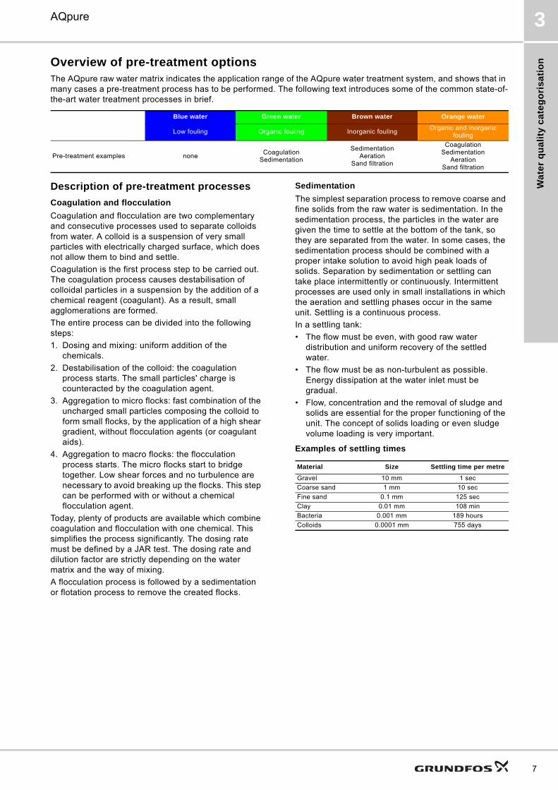
Overview of pre-treatment optionsThe AQpure raw water matrix indicates the application range of the AQpure water treatment system, and shows that in many cases a pre-treatment process has to be performed. The following text introduces some of the common state-of-the-art water treatment processes in brief.
Description of pre-treatment processes
Coagulation and flocculation
Coagulation and flocculation are two complementary and consecutive processes used to separate colloids from water. A colloid is a suspension of very small particles with electrically charged surface, which does not allow them to bind and settle.
Coagulation is the first process step to be carried out. The coagulation process causes destabilisation of colloidal particles in a suspension by the addition of a chemical reagent (coagulant). As a result, small agglomerations are formed.
The entire process can be divided into the following steps:
1. Dosing and mixing: uniform addition of the chemicals.
2. Destabilisation of the colloid: the coagulation process starts. The small particles' charge is counteracted by the coagulation agent.
3. Aggregation to micro flocks: fast combination of the uncharged small particles composing the colloid to form small flocks, by the application of a high shear gradient, without flocculation agents (or coagulant aids).
4. Aggregation to macro flocks: the flocculation process starts. The micro flocks start to bridge together. Low shear forces and no turbulence are necessary to avoid breaking up the flocks. This step can be performed with or without a chemical flocculation agent.
Today, plenty of products are available which combine coagulation and flocculation with one chemical. This simplifies the process significantly. The dosing rate must be defined by a JAR test. The dosing rate and dilution factor are strictly depending on the water matrix and the way of mixing.
A flocculation process is followed by a sedimentation or flotation process to remove the created flocks.
Sedimentation
The simplest separation process to remove coarse and fine solids from the raw water is sedimentation. In the sedimentation process, the particles in the water are given the time to settle at the bottom of the tank, so they are separated from the water. In some cases, the sedimentation process should be combined with a proper intake solution to avoid high peak loads of solids. Separation by sedimentation or settling can take place intermittently or continuously. Intermittent processes are used only in small installations in which the aeration and settling phases occur in the same unit. Settling is a continuous process.
In a settling tank:
• The flow must be even, with good raw water distribution and uniform recovery of the settled water.
• The flow must be as non-turbulent as possible. Energy dissipation at the water inlet must be gradual.
• Flow, concentration and the removal of sludge and solids are essential for the proper functioning of the unit. The concept of solids loading or even sludge volume loading is very important.
Examples of settling times
Blue water Green water Brown water Orange water
Low fouling Organic fouling Inorganic foulingOrganic and inorganic
fouling
Pre-treatment examples noneCoagulation
Sedimentation
SedimentationAeration
Sand filtration
CoagulationSedimentation
AerationSand filtration
Material Size Settling time per metre
Gravel 10 mm 1 sec
Coarse sand 1 mm 10 sec
Fine sand 0.1 mm 125 sec
Clay 0.01 mm 108 min
Bacteria 0.001 mm 189 hours
Colloids 0.0001 mm 755 days
7
Wa
ter q
ua
lity c
ate
go
risa
tion
8
AQpure3
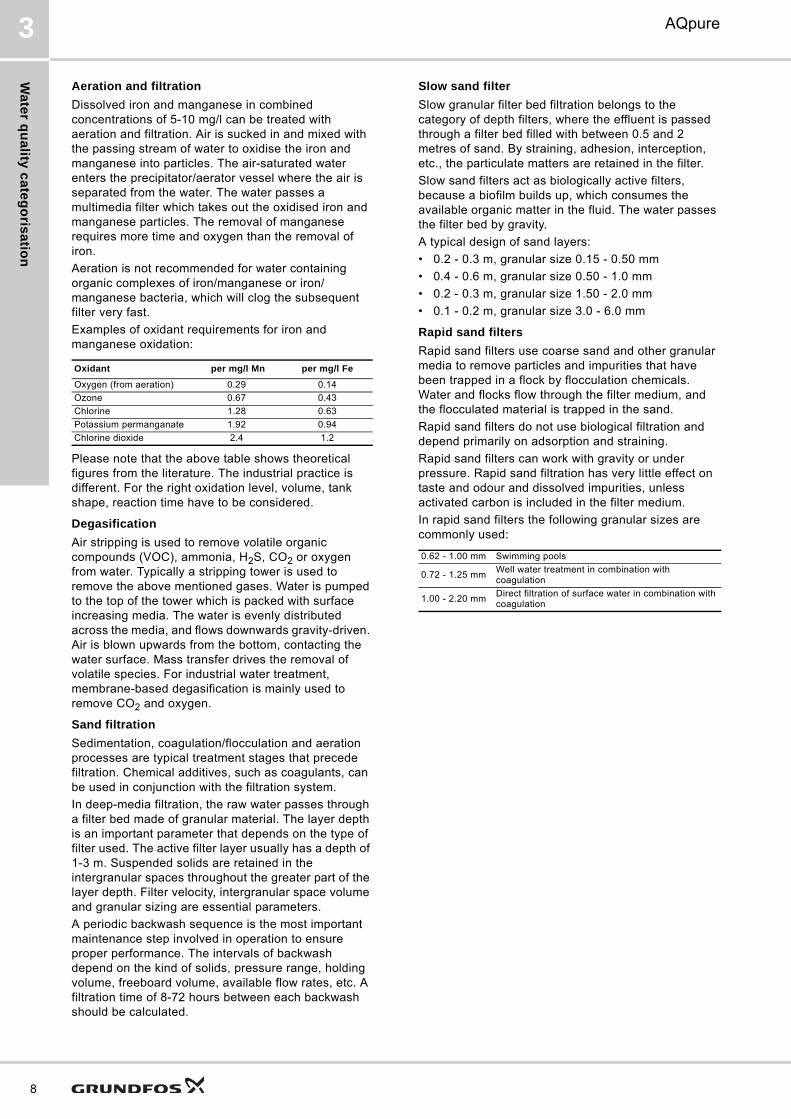
Aeration and filtration
Dissolved iron and manganese in combined concentrations of 5-10 mg/l can be treated with aeration and filtration. Air is sucked in and mixed with the passing stream of water to oxidise the iron and manganese into particles. The air-saturated water enters the precipitator/aerator vessel where the air is separated from the water. The water passes a multimedia filter which takes out the oxidised iron and manganese particles. The removal of manganese requires more time and oxygen than the removal of iron.
Aeration is not recommended for water containing organic complexes of iron/manganese or iron/manganese bacteria, which will clog the subsequent filter very fast.
Examples of oxidant requirements for iron and manganese oxidation:
Please note that the above table shows theoretical figures from the literature. The industrial practice is different. For the right oxidation level, volume, tank shape, reaction time have to be considered.
Degasification
Air stripping is used to remove volatile organic compounds (VOC), ammonia, H2S, CO2 or oxygen from water. Typically a stripping tower is used to remove the above mentioned gases. Water is pumped to the top of the tower which is packed with surface increasing media. The water is evenly distributed across the media, and flows downwards gravity-driven. Air is blown upwards from the bottom, contacting the water surface. Mass transfer drives the removal of volatile species. For industrial water treatment, membrane-based degasification is mainly used to remove CO2 and oxygen.
Sand filtration
Sedimentation, coagulation/flocculation and aeration processes are typical treatment stages that precede filtration. Chemical additives, such as coagulants, can be used in conjunction with the filtration system.
In deep-media filtration, the raw water passes through a filter bed made of granular material. The layer depth is an important parameter that depends on the type of filter used. The active filter layer usually has a depth of 1-3 m. Suspended solids are retained in the intergranular spaces throughout the greater part of the layer depth. Filter velocity, intergranular space volume and granular sizing are essential parameters.
A periodic backwash sequence is the most important maintenance step involved in operation to ensure proper performance. The intervals of backwash depend on the kind of solids, pressure range, holding volume, freeboard volume, available flow rates, etc. A filtration time of 8-72 hours between each backwash should be calculated.
Slow sand filter
Slow granular filter bed filtration belongs to the category of depth filters, where the effluent is passed through a filter bed filled with between 0.5 and 2 metres of sand. By straining, adhesion, interception, etc., the particulate matters are retained in the filter.
Slow sand filters act as biologically active filters, because a biofilm builds up, which consumes the available organic matter in the fluid. The water passes the filter bed by gravity.
A typical design of sand layers:
• 0.2 - 0.3 m, granular size 0.15 - 0.50 mm
• 0.4 - 0.6 m, granular size 0.50 - 1.0 mm
• 0.2 - 0.3 m, granular size 1.50 - 2.0 mm
• 0.1 - 0.2 m, granular size 3.0 - 6.0 mm
Rapid sand filters
Rapid sand filters use coarse sand and other granular media to remove particles and impurities that have been trapped in a flock by flocculation chemicals. Water and flocks flow through the filter medium, and the flocculated material is trapped in the sand.
Rapid sand filters do not use biological filtration and depend primarily on adsorption and straining.
Rapid sand filters can work with gravity or under pressure. Rapid sand filtration has very little effect on taste and odour and dissolved impurities, unless activated carbon is included in the filter medium.
In rapid sand filters the following granular sizes are commonly used:
Oxidant per mg/l Mn per mg/l Fe
Oxygen (from aeration) 0.29 0.14
Ozone 0.67 0.43
Chlorine 1.28 0.63
Potassium permanganate 1.92 0.94
Chlorine dioxide 2.4 1.2
0.62 - 1.00 mm Swimming pools
0.72 - 1.25 mmWell water treatment in combination with coagulation
1.00 - 2.20 mmDirect filtration of surface water in combination with coagulation

Pro
du
ct
co
nfi
gu
rati
on
AQpure 4
4. Product configuration
Configuration depending on water category
■ Built-in module❑ Optional module- Not selectable1) Must be combined with auxiliary equipment2) Includes 300 µm strainer
Type keyExample: AQP-UF-1-C1-PL-UV-D-SP-RM
AQpure selection toolGrundfos provides a selection tool for the easy configuration of AQpure.
Based on the determined water parameters and specific requirements, the appropriate combinations and accessories are suggested. The AQpure selection tool can be acquired from the local Grundfos representative.
UF process
only
Blue waterGround water, rain water
or public water
Green waterPond water
Brown waterRiver water in wet
season
Orange waterRivers and lakes in
tropical areas
Combination C11) C2 C3 C4 C5 C6 C7 C8 C9 C10 C11
Mo
du
les
Self-cleaning prefilter
- - - - - ■ ■ ■ ■ ■ ■
Standard UF ■ 2) ■ 2) ■ 2) ■ 2) ■ 2) ■ ■ ■ ■ ■ ■Air scouring - - - ■ ■ - ■ ■ ■ ■ ■Chlorination - ■ - ■ - ■ ■ ■ - ■ ■Internal CIP - - - - - ■ ■ - - ■ ■Level sensing ❑ ❑ ❑ ■ ■ ❑ ■ ❑ ■ ❑ ■Activated carbon filter
- - - ■ ■ - ■ - ■ - ■
UV disinfection ❑ - ■ - ■ ❑ ❑ - ■ ❑ ■Distribution ❑ ❑ ❑ ■ ■ ❑ ■ ❑ ■ ❑ ■Solar package ❑ ❑ ❑ ❑ ❑ ❑ ❑ ❑ ❑ ❑ ❑Remote management ❑ ■ ■ ■ ■ ■ ■ ■ ■ ■ ■
Code Description
Type AQP AQpure
Technology UF Ultrafiltration
Number of modules 1 1 module
Main combination
C1 Combination 1
C2 Combination 2
C3 Combination 3
C4 Combination 4
C5 Combination 5
C6 Combination 6
C7 Combination 7
C8 Combination 8
C9 Combination 9
C10 Combination 10
C11 Combination 11
Optional modules
Level sensingPL Level sensing
X No level sensing
UV disinfectionUV UV disinfection
X No UV
DistributionD Distribution
X No distribution
Solar packageSP Solar package
X No solar package
Remote managementRM Remote management (GRM)
X No remote management
9

Pro
du
ct d
es
crip
tion
10
AQpure5
5. Product description
AQpure modules
Fig. 4 Overview of AQpure modules
Self-cleaning prefilter
Standard UF
TM
06
52
53
42
15
Activated carbon filter
Internal CIP Air scouring UV disinfection
ChlorinationSelf-cleaning prefilterStandard UFLevel sensing
Distribution
Solar package
TM
06
38
99
12
15
The self-cleaning prefilter on the water inlet of the AQpure removes suspended solids > 100 μm.
Main components:
• Prefilter
• Motor valve
• Pressure sensor
TM
06
38
98
12
15
The standard UF module performs the ultrafiltration treatment step, and removes bacteria, viruses, and particles including colloids.
Main components:• UF membrane
• Feed pump
• Backwash pump
• Internal water tank
• Motor valves
• Pressure sensors
• Flow sensors
• Temperature sensor
• PLC
• Aluminium frame

Pro
du
ct
de
sc
rip
tio
n
AQpure 5
Air scouring
Chlorination
Internal CIP
Level sensing
Activated carbon filter
TM
06
52
54
42
15
The air scouring/PDT module blows a large amount of air into the UF membrane to improve the backwash. The Pressure Decay Test (PDT) can be performed with the air scouring/PDT module.
Main component:
• Air pump
TM
06
39
00
12
15
The chlorination module offers the possibility to disinfect the produced water with residual effect. Chlorine is also used to enhance backwash of the UF membrane and internal CIP (Clean In Place) process.
Main components:
• Dosing pump
• Chlorine tank with level switch
TM
06
38
95
12
15
In combination with the chlorination module, the internal Clean In Place (CIP) module provides improved cleaning of the UF membrane. The combination of both is also referred to as Chemical Enhanced Backwash (CEB).
Main components:
• Circulation pump
• Dosing pump
• Chlorine tank with level switch
TM
06
43
81
211
5
A pressure sensor is used for the tank level control of the external buffer tank. The sensor signals when to start and stop the production and when to start and stop transferring water from the internal tank to the external buffer tank.
TM
06
52
55
42
15
The activated carbon filter module removes chemicals from the water, particularly organic chemicals that are responsible for odour and taste.
Main components:
• Activated carbon filter
• Multiport valve (MPV)
• Pressure sensors
• Solenoid valve
• Cartridge filter
11
Pro
du
ct d
es
crip
tion
12
AQpure5
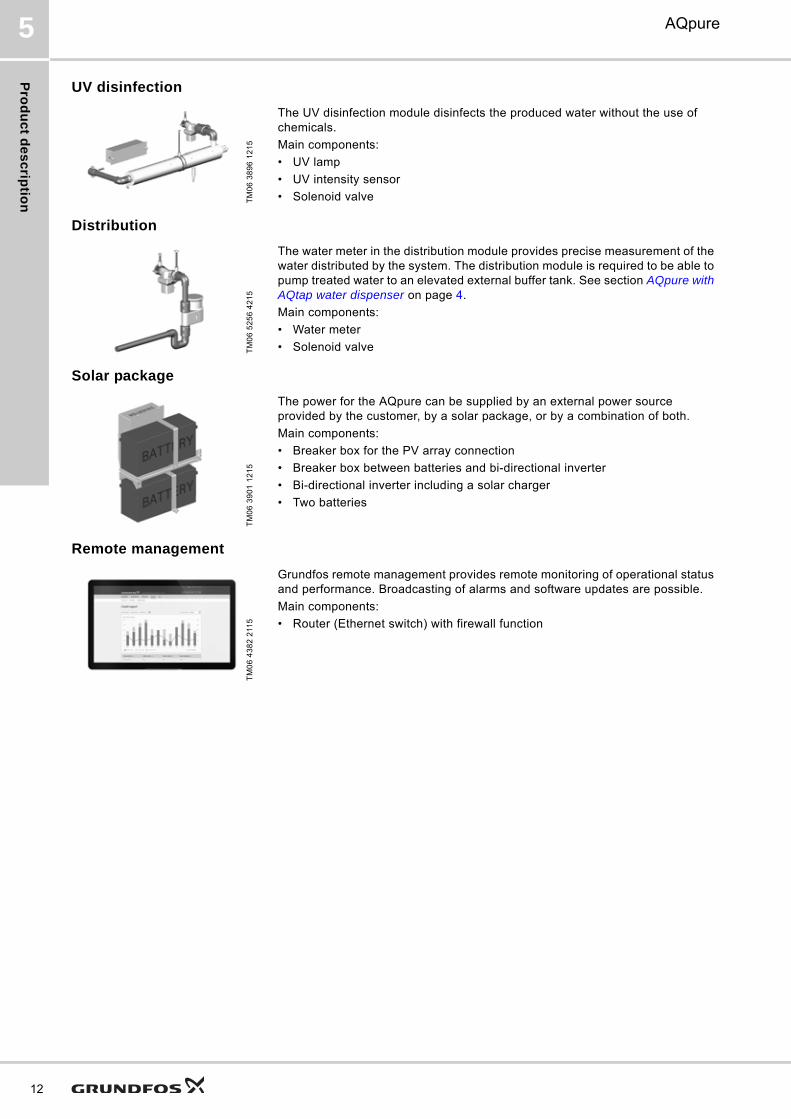
UV disinfection
Distribution
Solar package
Remote management
TM
06
38
96
12
15
The UV disinfection module disinfects the produced water without the use of chemicals.
Main components:
• UV lamp
• UV intensity sensor
• Solenoid valve
TM
06
52
56
42
15
The water meter in the distribution module provides precise measurement of the water distributed by the system. The distribution module is required to be able to pump treated water to an elevated external buffer tank. See section AQpure with AQtap water dispenser on page 4.
Main components:
• Water meter
• Solenoid valve
TM
06
39
01
12
15
The power for the AQpure can be supplied by an external power source provided by the customer, by a solar package, or by a combination of both.
Main components:
• Breaker box for the PV array connection
• Breaker box between batteries and bi-directional inverter
• Bi-directional inverter including a solar charger
• Two batteries
TM
06
43
82
211
5
Grundfos remote management provides remote monitoring of operational status and performance. Broadcasting of alarms and software updates are possible.
Main components:
• Router (Ethernet switch) with firewall function

Pro
du
ct
de
sc
rip
tio
n
AQpure 5
Technical data
Dimensions
Fig. 5 Front and side view of an AQpure system
Fig. 6 Top view of an AQpure system
Transport dimensions and weights
Water production 0.5 to 2 m3/h
Membrane type Hollow fibre, dead-end, outside-in
Membrane material PVDF
Membrane pore size 0.03 μm
Control strategy Parametric to be very flexible
Inlet pressure max. 1 bar at 1 m3/h
Power supply 200-240 V, 1-phase, 50/60 Hz
Control interface PLC based 7" touchscreen
Weight Empty: 400-615 kg; Filled: 750-1165 kg
TM
06
38
90
_2
12
15
1464
800
921
1785
2296
1804 19
0320
40
114
51.3
420.4
1475
1200*
45
269
* Space required for maintenance of UV disinfection module
TM
06
47
69
29
15
41
58
294
Description
Packing box dimensions[mm] Weight
[kg]Length Width Height
AQpure system with standard UF module only
1660 1030 2240 429
AQpure system with all modules
1740 1135 2240 612
External CIP unit 840 850 1215 93
UF membrane 2000 355 550 75
Activated carbon filter 2000 500 565 67
13
Pro
du
ct s
ele
ctio
n
14
AQpure6
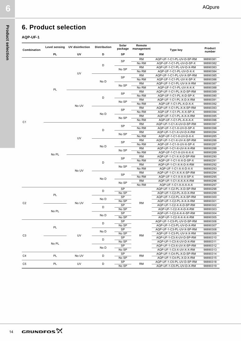
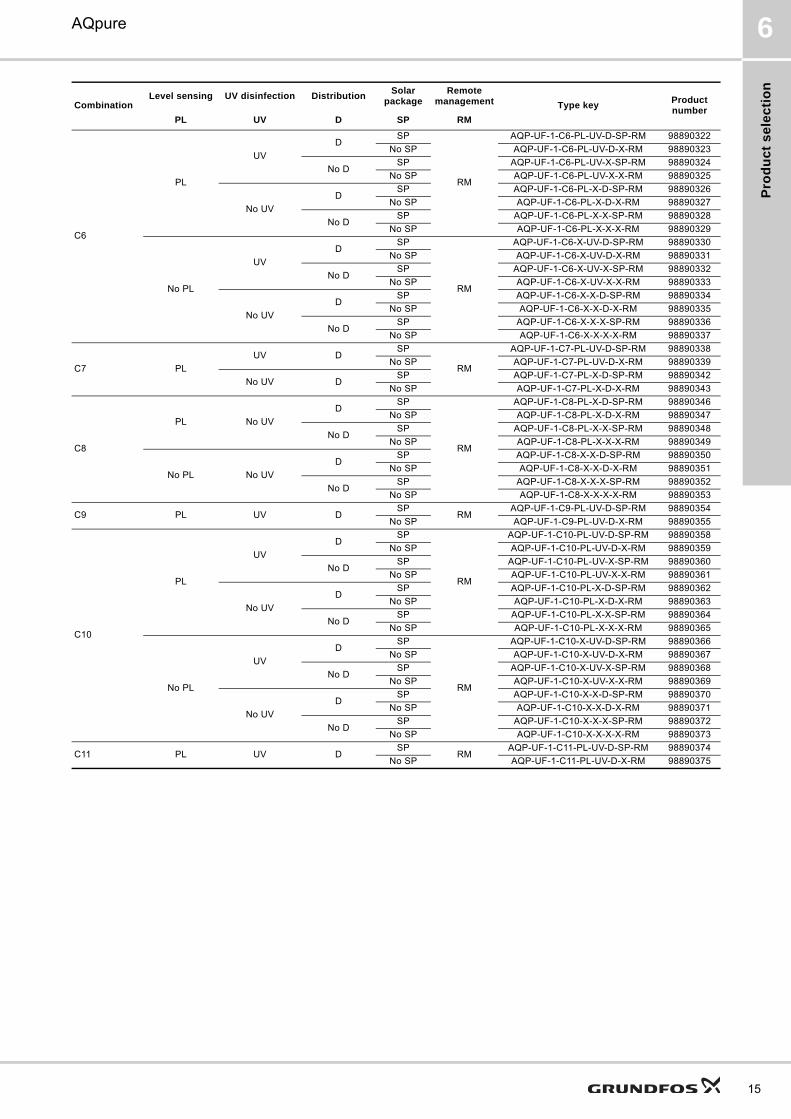
6. Product selection
AQP-UF-1
CombinationLevel sensing UV disinfection Distribution
Solar package
Remote management Type key
Product number
PL UV D SP RM
C1
PL
UV
D
SPRM AQP-UF-1-C1-PL-UV-D-SP-RM 98890381
No RM AQP-UF-1-C1-PL-UV-D-SP-X 98890382
No SPRM AQP-UF-1-C1-PL-UV-D-X-RM 98890383
No RM AQP-UF-1-C1-PL-UV-D-X-X 98890384
No D
SPRM AQP-UF-1-C1-PL-UV-X-SP-RM 98890385
No RM AQP-UF-1-C1-PL-UV-X-SP-X 98890386
No SPRM AQP-UF-1-C1-PL-UV-X-X-RM 98890387
No RM AQP-UF-1-C1-PL-UV-X-X-X 98890388
No UV
D
SPRM AQP-UF-1-C1-PL-X-D-SP-RM 98890389
No RM AQP-UF-1-C1-PL-X-D-SP-X 98890390
No SPRM AQP-UF-1-C1-PL-X-D-X-RM 98890391
No RM AQP-UF-1-C1-PL-X-D-X-X 98890392
No D
SPRM AQP-UF-1-C1-PL-X-X-SP-RM 98890393
No RM AQP-UF-1-C1-PL-X-X-SP-X 98890394
No SPRM AQP-UF-1-C1-PL-X-X-X-RM 98890395
No RM AQP-UF-1-C1-PL-X-X-X-X 98890396
No PL
UV
D
SPRM AQP-UF-1-C1-X-UV-D-SP-RM 98890397
No RM AQP-UF-1-C1-X-UV-D-SP-X 98890398
No SPRM AQP-UF-1-C1-X-UV-D-X-RM 98890284
No RM AQP-UF-1-C1-X-UV-D-X-X 98890285
No D
SPRM AQP-UF-1-C1-X-UV-X-SP-RM 98890286
No RM AQP-UF-1-C1-X-UV-X-SP-X 98890287
No SPRM AQP-UF-1-C1-X-UV-X-X-RM 98890288
No RM AQP-UF-1-C1-X-UV-X-X-X 98890289
No UV
D
SPRM AQP-UF-1-C1-X-X-D-SP-RM 98890290
No RM AQP-UF-1-C1-X-X-D-SP-X 98890291
No SPRM AQP-UF-1-C1-X-X-D-X-RM 98890292
No RM AQP-UF-1-C1-X-X-D-X-X 98890293
No D
SPRM AQP-UF-1-C1-X-X-X-SP-RM 98890294
No RM AQP-UF-1-C1-X-X-X-SP-X 98890295
No SPRM AQP-UF-1-C1-X-X-X-X-RM 98890296
No RM AQP-UF-1-C1-X-X-X-X-X 98890297
C2
PL
No UV
DSP
RM
AQP-UF-1-C2-PL-X-D-SP-RM 98890298
No SP AQP-UF-1-C2-PL-X-D-X-RM 98890299
No DSP AQP-UF-1-C2-PL-X-X-SP-RM 98890300
No SP AQP-UF-1-C2-PL-X-X-X-RM 98890301
No PL
DSP AQP-UF-1-C2-X-X-D-SP-RM 98890302
No SP AQP-UF-1-C2-X-X-D-X-RM 98890303
No DSP AQP-UF-1-C2-X-X-X-SP-RM 98890304
No SP AQP-UF-1-C2-X-X-X-X-RM 98890305
C3
PL
UV
DSP
RM
AQP-UF-1-C3-PL-UV-D-SP-RM 98890306
No SP AQP-UF-1-C3-PL-UV-D-X-RM 98890307
No DSP AQP-UF-1-C3-PL-UV-X-SP-RM 98890308
No SP AQP-UF-1-C3-PL-UV-X-X-RM 98890309
No PL
DSP AQP-UF-1-C3-X-UV-D-SP-RM 98890310
No SP AQP-UF-1-C3-X-UV-D-X-RM 98890311
No DSP AQP-UF-1-C3-X-UV-X-SP-RM 98890312
No SP AQP-UF-1-C3-X-UV-X-X-RM 98890313
C4 PL No UV DSP
RMAQP-UF-1-C4-PL-X-D-SP-RM 98890314
No SP AQP-UF-1-C4-PL-X-D-X-RM 98890315
C5 PL UV DSP
RMAQP-UF-1-C5-PL-UV-D-SP-RM 98890318
No SP AQP-UF-1-C5-PL-UV-D-X-RM 98890319
Pro
du
ct
se
lec
tio
n
AQpure 6
C6
PL
UV
DSP
RM
AQP-UF-1-C6-PL-UV-D-SP-RM 98890322
No SP AQP-UF-1-C6-PL-UV-D-X-RM 98890323
No DSP AQP-UF-1-C6-PL-UV-X-SP-RM 98890324
No SP AQP-UF-1-C6-PL-UV-X-X-RM 98890325
No UV
DSP AQP-UF-1-C6-PL-X-D-SP-RM 98890326
No SP AQP-UF-1-C6-PL-X-D-X-RM 98890327
No DSP AQP-UF-1-C6-PL-X-X-SP-RM 98890328
No SP AQP-UF-1-C6-PL-X-X-X-RM 98890329
No PL
UV
DSP
RM
AQP-UF-1-C6-X-UV-D-SP-RM 98890330
No SP AQP-UF-1-C6-X-UV-D-X-RM 98890331
No DSP AQP-UF-1-C6-X-UV-X-SP-RM 98890332
No SP AQP-UF-1-C6-X-UV-X-X-RM 98890333
No UV
DSP AQP-UF-1-C6-X-X-D-SP-RM 98890334
No SP AQP-UF-1-C6-X-X-D-X-RM 98890335
No DSP AQP-UF-1-C6-X-X-X-SP-RM 98890336
No SP AQP-UF-1-C6-X-X-X-X-RM 98890337
C7 PL
UV DSP
RM
AQP-UF-1-C7-PL-UV-D-SP-RM 98890338
No SP AQP-UF-1-C7-PL-UV-D-X-RM 98890339
No UV DSP AQP-UF-1-C7-PL-X-D-SP-RM 98890342
No SP AQP-UF-1-C7-PL-X-D-X-RM 98890343
C8
PL No UV
DSP
RM
AQP-UF-1-C8-PL-X-D-SP-RM 98890346
No SP AQP-UF-1-C8-PL-X-D-X-RM 98890347
No DSP AQP-UF-1-C8-PL-X-X-SP-RM 98890348
No SP AQP-UF-1-C8-PL-X-X-X-RM 98890349
No PL No UV
DSP AQP-UF-1-C8-X-X-D-SP-RM 98890350
No SP AQP-UF-1-C8-X-X-D-X-RM 98890351
No DSP AQP-UF-1-C8-X-X-X-SP-RM 98890352
No SP AQP-UF-1-C8-X-X-X-X-RM 98890353
C9 PL UV DSP
RMAQP-UF-1-C9-PL-UV-D-SP-RM 98890354
No SP AQP-UF-1-C9-PL-UV-D-X-RM 98890355
C10
PL
UV
DSP
RM
AQP-UF-1-C10-PL-UV-D-SP-RM 98890358
No SP AQP-UF-1-C10-PL-UV-D-X-RM 98890359
No DSP AQP-UF-1-C10-PL-UV-X-SP-RM 98890360
No SP AQP-UF-1-C10-PL-UV-X-X-RM 98890361
No UV
DSP AQP-UF-1-C10-PL-X-D-SP-RM 98890362
No SP AQP-UF-1-C10-PL-X-D-X-RM 98890363
No DSP AQP-UF-1-C10-PL-X-X-SP-RM 98890364
No SP AQP-UF-1-C10-PL-X-X-X-RM 98890365
No PL
UV
DSP
RM
AQP-UF-1-C10-X-UV-D-SP-RM 98890366
No SP AQP-UF-1-C10-X-UV-D-X-RM 98890367
No DSP AQP-UF-1-C10-X-UV-X-SP-RM 98890368
No SP AQP-UF-1-C10-X-UV-X-X-RM 98890369
No UV
DSP AQP-UF-1-C10-X-X-D-SP-RM 98890370
No SP AQP-UF-1-C10-X-X-D-X-RM 98890371
No DSP AQP-UF-1-C10-X-X-X-SP-RM 98890372
No SP AQP-UF-1-C10-X-X-X-X-RM 98890373
C11 PL UV DSP
RMAQP-UF-1-C11-PL-UV-D-SP-RM 98890374
No SP AQP-UF-1-C11-PL-UV-D-X-RM 98890375
CombinationLevel sensing UV disinfection Distribution
Solar package
Remote management Type key
Product number
PL UV D SP RM
15

Se
rvic
e o
fferin
gs
16
AQpure7
7. Service offerings
The service offerings described here ensure optimal functioning of the AQpure system with respect to:
• highly optimised system performance
• minimal energy consumption
• reduced operational costs
• low downtime on site
All service offerings listed below can be purchased individually and locally at Grundfos Service & Solutions. Our Authorised Service Partner network helps us secure a dependable and global availability of service products.
For further information contact your local Grundfos company or service partner or see:
http://www.grundfos.com/service-support.html
Installation and operation
Repair and maintenance
Spare parts and maintenance kits
Surveillance and mobility
Commissioning
• Check of installationDuring commissioning, all aspects of your Grundfos AQpure system are checked, if it is correctly installed and ready for start-up.
• CommissioningCommissioning is crucial to avoid breakdown of the AQpure system during operation.
• Train the operatorCertified service staff trains your operator in the basic maintenance tasks and writes a detailed report including the activities realised, the parameters measured, and gives recommendations. Your operator will be able to keep the system running at optimal conditions.
Service contracts
• Professional maintenance and repair serviceWith a Grundfos service contract, you get dependable and professional service and maintenance, making sure that your installation remains in top condition and runs in an energy efficient manner.
• Two-level service contractTo suit your needs, two different levels of service contracts are available: Basic and Advanced.
• Maximal reliability at low costsRegular scheduled service work with replacement of components maximises the reliability of the system and keeps the running costs low.
On-site repair
Certified service staff takes care of maintenance and repair tasks. This provides you with the following advantages:• Minimised downtime and expenditure due to fast and efficient repair work• Repair work is performed in such a way that the product warranty remains valid• No need to spend time and resources in dismantling installations, sending components for
repairs, and reassembling installations afterwards• Clear overview of repair costs
Spare parts and maintenance kits
• Each maintenance kit is tailor-made for one specific maintenance operation.• One-stop shop solution: You'll get all the suitable original spare parts and maintenance kits at
one place.• Spare parts can be ordered at the local Grundfos sales company or the Service and Sales
Partner.• Grundfos Distribution Service offers 24/7 global delivery options
Grundfos Remote Management
Expert service engineers perform remote monitoring of the key parameters of your AQpure system.• When a critical event occurs, you are informed immediately by a warning or alarm, which
avoids a breakdown of your system.• Your operator receives assistance and recommendations• Site visits for troubleshooting are coordinated• A detailed report that highlights potential problems, gives recommendations and analyses data
is sent periodically.
Ac
ce
ss
ori
es
an
d s
pa
re p
art
s
AQpure 8
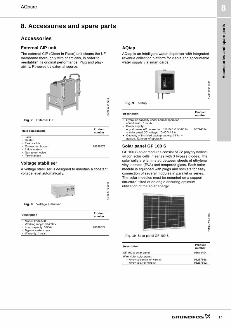
8. Accessories and spare parts
Accessories
External CIP unitThe external CIP (Clean In Place) unit cleans the UF membrane thoroughly with chemicals, in order to reestablish its original performance. Plug and play-ability. Powered by external source.
Fig. 7 External CIP
Voltage stabiliserA voltage stabiliser is designed to maintain a constant voltage level automatically.
Fig. 8 Voltage stabiliser
AQtapAQtap is an intelligent water dispenser with integrated revenue collection platform for viable and accountable water supply via smart cards.
Fig. 9 AQtap
Solar panel GF 100 SGF 100 S solar modules consist of 72 polycrystalline silicon solar cells in series with 3 bypass diodes. The solar cells are laminated between sheets of ethylene vinyl acetate (EVA) and tempered glass. Each solar module is equipped with plugs and sockets for easy connection of several modules in parallel or series. The solar modules must be mounted on a support structure, tilted at an angle ensuring optimum utilisation of the solar energy.
Fig. 10 Solar panel GF 100 S
TM
06
52
57
42
15
Main componentsProduct number
• Tank• Heater• Float switch• Connection hoses• 2 flow meters• Non-return valve• Terminal box
98890378
TM
06
47
73
30
15
DescriptionProduct number
• Model: DVR-590• Working range: 90-290 V• Load capacity: 5 KVA• Bypass system: yes• Warranty: 1 year
98890379
TM
06
47
65
29
15
DescriptionProduct number
• Hydraulic capacity under normal operation conditions: ~ 1 m3/h
• Power supply:– grid power AC connection: 110-240 V, 50/60 Hz– solar panel DC voltage: 15-45 V / 3 A
• Capacity of included backup-battery: 18 Ah = approx. 12 hours of operation
98794194
TM
06
47
68
29
15
DescriptionProduct number
GF 100 S solar panel 98614404
Wire kit for solar panel:– Array-to-controller wire kit– Array-to-array wire kit
9825786898257892
17

Ac
ce
ss
orie
s a
nd
sp
are
pa
rts
18
AQpure8
Option 1
3 solar panels are connected in series. 5 sets of 3 solar panels each are connected in parallel.
It requires:
• 1 array-to-controller wire kit
• 4 array-to-array wire kits
Fig. 11 Option 1: arrangement of solar panels
Option 2
2 solar panels are connected in series. 7 sets of 2 solar panels each are connected in parallel.
It requires:
• 2 array-to-controller wire kits
• 6 array-to-array wire kits
Fig. 12 Option 2: arrangement of solar panels
Grundfos water quality toolboxThe Grundfos water quality toolbox is a helpful tool to check and monitor the quality of the raw water, the feed water and the produced water. Portable devices and reagents that allow qualitative and quantitative parameter measurement are arranged in a suitcase for field testing. With the Grundfos water quality toolbox, it is easy to categorise the raw water and to select the suitable combination of AQpure modules.
Fig. 13 Water quality toolbox
Spare parts
TM
06
46
59
29
15
Description
• Voltage: 112.8 VDC• Open circuit voltage:132.6 VDC• Current: 13.75 A• Power: 1500 W• Dimensions of one panel: 1001*734*34 mm (length/width/height)
TM
06
46
60
29
15
Description
• Voltage: 75.2 VDC• Open circuit voltage: 88.4 VDC• Current: 19.25 A• Power: 1400 W• Dimensions of one panel: 1001*734*34 mm (length/width/height)
TM
06
54
60
47
15
Main componentsProduct number
• Portable incubator heater• Photometer• Conductivity measuring device• SDI15 measuring device• Turbidity measuring device• Fe, Mn, pH, TOC, DOC vials• Residual chlorine test• Syringes, filters and other accessories• Instructions
99013132
Module DescriptionProduct number
Standard UFKit, maintenance feed pump/ backwash pump
99025243
Spare, UF membrane element 99025244
Prefilter Kit, prefilter screen 99025245

Ap
pe
nd
ix
AQpure 9
9. Appendix
Explanation of water parameters
Water parameter Unit Interpretation Source
DOC(dissolved organic carbon)
[mg/l]
• The amount of carbon bound in an organic compound and is often used as a non-specific indicator of water quality.
• Measures CO2 formed when organic carbon is oxidized and/or when inorganic carbon is acidified and then subtract the inorganic carbon from the total carbon.
• Water needs to be filtered with 0.45 μm filter (preferred pre-flushed filter).
ISO 8245:1999 ASTM D7573-09
UV254 [1/m]• Organics with a high degree of conjugation absorb light in the UV at wavelength
of 254 nm of the electromagnetic spectrum, the extent the adsorption indicates the content of humic substances in water.
UV spectrophotometer at the wavelength of 254 nm
COD(chemical oxygen demand)
[mg/l]• Is commonly used to indirectly measure the amount of organic compounds in
water, indicates the mass of oxygen consumed per liter of solution.
ISO 15705:2002, reviewed in 2013ASTM D1252-06(2012)
Oil [mg/l]• Petroleum compounds in water or oil used in industry can be released into water
source due to heavy precipitation, vehicle accident, et al.• If oil contact with membrane, it is very difficult to be removed.
ISO 9377-2:2000ASTM D7066-04(2011)
Turbidity [NTU]
• Measure for the amount of particles in the water• Typically measured by light extinction in a water sample• Units:
– FNU indicates attenuation through the sample– NTU indicates scattered light (more focus on small particles)– Turbidity in FNU is not the same as in NTU (latter is preferred)
ISO 15715:2003 ASTM D7315-12
TSS(total suspended solids)
[mg/l]
• Solids in water that can be trapped by a filter with a pore size of 0.45 µm. TSS can include a wide variety of material, such as silt, decaying plant and animal matter, industrial wastes, and sewage. High concentrations of suspended solids can cause many problems for stream health and aquatic life.
ASTM D5907-13
SDI15(Silt Density Index)
• A measure for the fouling potential for water• Based on standard filtration protocol with micro filtration membranes
ASTM D4189-07(2014)
Fe/Mn [mg/l]
• Water percolating through soil and rock dissolves iron and manganese.• In groundwater due to low oxygen content and pH, water containing dissolved
iron or manganese appears colourless, but after contacting with oxygen iron changes to reddish-brown while manganese forms a black residue and both foul membrane heavily.
ASTM D1068-10ASTM D858-12
Water hardness(CaCO3)
[mg/l]
• Water hardness is the measure of concentration of divalent metal ions such as Ca/Mg per volume of water. It is common to use as unit of this parameter CaCO3equivalents in ppm or mg/l
• High content of Ca/Mg has high mineral content due to water percolating through deposits of calcium and magnesium-containing minerals such as limestone, chalk and dolomite.
• Hard drinking water is generally not harmful to one's health, but can pose serious problems in industrial settings. Under high pH CIP values they may sediment onto membrane and lead to severe fouling.
ASTM D511-14ASTM D1126-12
Conductivity [µS/cm]• Presents the ability to conduct electricity and indicating the ionic content in a
solution.
ASTM D1125-14ISO 7888:1985 (reviewed in 2012)
pH
• Presents the acidity or basicity of an aqueous solution. Solutions with a pH less than 7 are said to be acidic and solutions with a pH greater than 7 are basic or alkaline
• pH is the negative logarithm of the activity of the (solvated) hydronium ion.
ISO 10523:2008ASTM D1293-12
Temperature [°C]
• Temperature affects the viscosity of water. A low temperature indicates more energy needed to push water passing through membrane and correspondingly high transmembrane pressure.
• Cold temperatures are an indication of infiltration of ground water to the raw water source (to be considered during process design)
19

Ap
pe
nd
ix
20
AQpure9
Piping and instrumentation diagram (PID)
Fig. 14 PID of an AQpure water treatment system
Symbols of the PID
TM
06
38
92
12
15
UVT
P3
M
P2
M
P1
M
T1
M
P5
P4
P6
P7A
B
C
D
E
T
FI
FI
P7
••
M
UV disinfection
Air scouring
Throttle valve
Water quality sample
External buffer tank
External buffer tank
Waste tank
Standard UF
Food grade tank
Multiport valve
NaOCl chlorination
CRNE 5-4 pump
Self-cleaning prefilter
Internal CIP
CRNE 5-4 pump
Chemical tankwith lid
Heater
Water quality sample
Backwash out
Activated carbonfilter
Cartridge filterThermostat
External CIP connection
Hydraulic connection
Flow sensor Pump Solenoid valve Pressure relief valve
Pressure sensor or temperature sensor
Pipe or hose Non-return valve Float switch
Motor valve Compressor Manual valve Strainer
M

Gru
nd
fos
Pro
du
ct
Ce
nte
r
21
AQpure 10
10. Grundfos Product Center
Subject to alterations.
All the information you need in one place Downloads
Performance curves, technical specifications, pictures, dimensional drawings, motor curves, wiring diagrams, spare parts, service kits, 3D drawings, documents, system parts. The Product Center displays any recent and saved items - including complete projects - right on the main page.
On the product pages, you can download installation and operating instructions, data booklets, service instructions, etc. in PDF format.
"SIZING" enables you to size a pump based on entered data and selection choices.
Online search and sizing tool to help you make the right choice.
http://product-selection.grundfos.com
"REPLACEMENT" enables you to find a replacement product. Search results will include information on the following:
• the lowest purchase price• the lowest energy consumption• the lowest total life cycle cost.
"CATALOGUE" gives you access to the Grundfos product catalogue.
"LIQUIDS" enables you to find pumps designed for aggressive, flammable or other special liquids.

GRUNDFOS A/S DK-8850 Bjerringbro . DenmarkTelephone: +45 87 50 14 00www.grundfos.com
98890935 1215
ECM: 1156120 Th
e n
am
e G
run
dfo
s, t
he
Gru
nd
fos
log
o,
an
d b
e t
hin
k i
nn
ov
ate
are
re
gis
tere
d t
rad
em
ark
s o
wn
ed
by
Gru
nd
fos
Ho
ldin
g A
/S o
r G
run
dfo
s A
/S,
De
nm
ark
. A
ll ri
gh
ts r
ese
rve
d w
orl
dw
ide
.©
Co
pyr
igh
t G
run
dfo
s H
old
ing
A/S