modulation and demodulation. radio telescopes used in radio astronomy arecibo observatory, puerto...
TRANSCRIPT

Modulation and Demodulation

Radio telescopes used in radio astronomy
Arecibo Observatory, Puerto Rico Very Large Array, New Mexico

As in movies
• Contact– https://www.youtube.com/watch?v=C9DuMK0uo
1c• Goldeneyes
– https://www.youtube.com/watch?v=MH2qnn4D0kY
3

Why Do We Need A Large Radio Telescope like This?
• Difficulties in low frequency communications– Many astronomical objects emit radiation at radio
frequency (RF)• RF is much small than the frequency of visible lights
– Antenna size: the same magnitude of the wavelength of a signal
– Low frequency signals require large antennas.
f *l = c (speed of light)
We need a way to transmit and receive low frequency signals easily!

Modulation and Demodulation
• Modulation: use a high frequency signal to carry information about a low-frequency signal (e.g., sound waves).
• Demodulation: recreate the low-frequency signal from the high frequency signal.

More Motivation for Modulation
• Interference– Signals occupy similar frequency bands
• TV, radio stations
• Modulation: allow different signals to be transmitted simultaneously with a single device– Radio and TV channels: with different frequencies.

7
Methods for Modulation
• In essence, a sender must change one of the characteristics of the carrier
• Amplitude modulation• Frequency modulation• Phase shift modulation
y = A sin(2 p f t + f)

8
Amplitude Modulation (AM)
• The amplitude of a carrier is modified in proportion to the information signal.– The frequency of the carrier is fixed.
carrier
information

Example
• The original signal: sin(x)• The carrier: sin(35x)
• Multiplication – sin(x) * sin(35x)

10
Problems of Amplitude Modulation• Power level to zero
• Practical systems do not allow for a modulated signal to approach zero
• In practice, modulation only changes the amplitude of a carrier slightly– Keeping the carrier wave near maximum

Example
• The carrier: sin(35x)• The signal: sin(x)
• AM with a modulation index a– [ a * sin(x) + mi ] * sin (35x)
• a = 0.3, mi =1

12
Frequency Modulation (FM) • Signal amplitude can be easily affected by the
environment. • Signal frequency, however, is quite stable.• In FM, frequency changes according to the signal.

13
Frequency Modulation (FM) • The carrier: sin(5t)• The signal: sin(t)
• FM– sin ( (sin(t) + 2) * 5 t)
Q: Is the constant “2" necessary here?

14
Modulation of Digital Signals • A different term: shift keying
– Instead of a continuum of possible values, digital shift keying has a fixed set
• Mapping to the power levels of a digital signal

15
a carrier wave
a digital input signal
amplitude shift keying
frequency shift keying

Exercise: ASK
Consider the input signal with 3 levels shown above. Assume we want to use the following sine wave as the carrier.
10 sin(2 p 2 t)
And we want to use the following ASK scheme – 15V level ‘1’– 10V level ‘0’– 5V level ‘-1’
Please draw the resulting waveform after modulation.
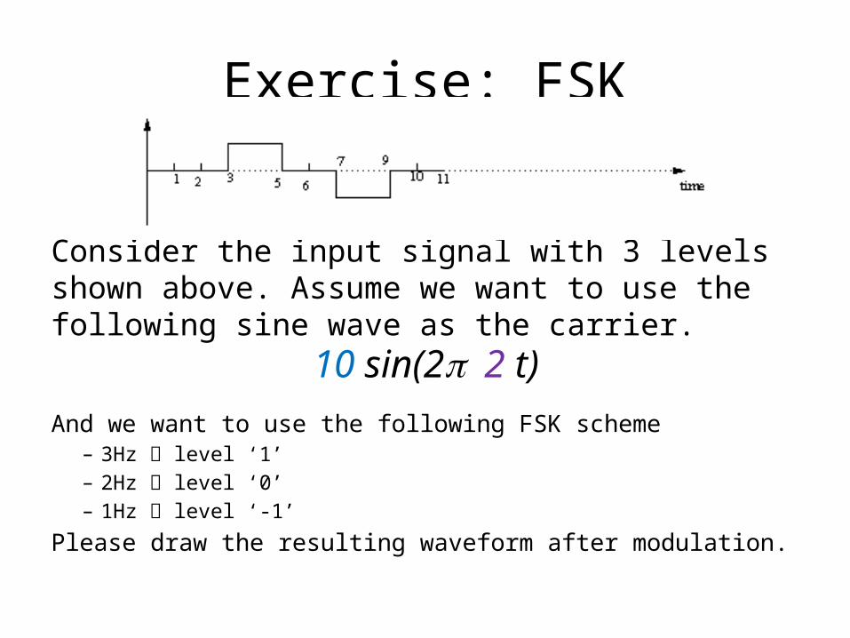
Exercise: FSK
Consider the input signal with 3 levels shown above. Assume we want to use the following sine wave as the carrier.
10 sin(2 p 2 t)
And we want to use the following FSK scheme – 3Hz level ‘1’– 2Hz level ‘0’– 1Hz level ‘-1’
Please draw the resulting waveform after modulation.

Efficiency Issues of ASK and FSK
• Must capture the amplitude or frequency information of the carrier– Require at least one cycle of a carrier wave to send a
single bit– Transmission capacity is limited by the carrier frequency!
• A single sine wave circle– One amplitude– One frequency– Can be shifted with multiple phases!

19
Phase Shift Keying (PSK) • Almost every real world modem use PSK to send
more bits.– PSK changes the phase of the carrier wave abruptly.– Each such change is called a phase shift
• On a sine wave, each point correspond to a phase (angle)
0°
90°
180°
270°
360°

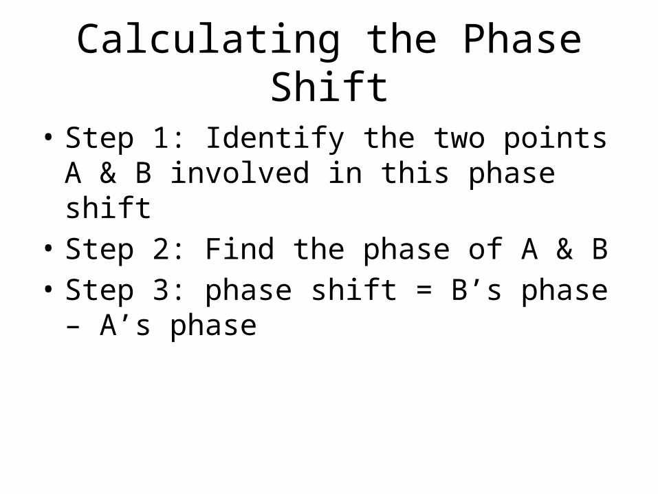
Calculating the Phase Shift
20
• Example: • The first change:
• Point A’s phase: 90°• Point B’s phase: 270°• Phase change: 270° - 90° = 180°
• The second change:• 360° - 180° = 180°
• The third change?
A
B
A BA B
Calculating the Phase Shift
• Step 1: Identify the two points A & B involved in this phase shift
• Step 2: Find the phase of A & B• Step 3: phase shift = B’s phase – A’s phase

22
Phase Shift and a Constellation Diagram
• How to encode data into phase shifts?– A sender and receiver can agree on the number of
bits per second– Use different phase shifts to denote the data bits.
• A constellation diagram is used to express the exact assignment of data bits to specific phase changes

23
Constellation Diagram
Example: Assume 4 bits / cycle:
1 1 0 0
1 bit / shift
2-PSK

Exercise: PSK
Assume we want to use the following sine wave as the carrier.
sin(2 p t)
And we want to use the 2-PSK to send four bits “0101” in one second. Please draw the resulting waveform after modulation.

25
Phase Shift and Constellation Diagram
Phase Shift 45° 135° 215° 305°
Bit Value 00 01 10 11
2 bit / shift
4-PSK

26
Phase Shift and a Constellation Diagram
• In theory, it is possible to increase the data rate by decreasing the angular difference between phases– 4-PSK 8-PSK
• 90° 45°
– 16-PSK: 22.5°
• Noise and distortion limit the ability of practical systems to distinguish among arbitrarily small differences in phase changes.

27
Quadrature Amplitude Modulation (QAM)
• ASK + PSK• In a constellation diagram, we use distance from
the origin as a measure of amplitude
16QAM

28
45 ° shifted away from the original signal
67.5 ° shifted away from the original signal, but only 22.5 ° from the previous signal

29
MODEM: MOdulator + DEModulator
• Usually within the same device– Each location needs both a modulator to send data
and a demodulator to receive data.– Most communication systems are full duplex.
After Class Reading
• Sections 10.14 – 10.16: Dial-up models and QAM