modulation of optical spatial coherence by surface …tvisser/plasmonmodulatedcoherence.pdf ·...
TRANSCRIPT

Modulation of optical spatial coherenceby surface plasmon polaritonsSHAWN DIVITT,1 MARTIN FRIMMER,1 TACO D. VISSER,2,3 AND LUKAS NOVOTNY1,*1Photonics Laboratory, ETH Zürich, 8093 Zürich, Switzerland2Faculty of Electrical Engineering, Mathematics and Computer Science, Delft University of Technology, Delft, The Netherlands3Department of Physics and Astronomy, Vrije Universiteit, Amsterdam, The Netherlands*Corresponding author: [email protected]
Received 28 April 2016; revised 3 June 2016; accepted 4 June 2016; posted 6 June 2016 (Doc. ID 262276); published 29 June 2016
The interference pattern observed in Young’s double-slit ex-periment is intimately related to the statistical correlationsof the waves emitted by the slits. As the waves in the slitsbecome more correlated, the visibility of the interferencepattern increases. Here, we experimentally modulate thestatistical correlations between the optical fields emittedby a pair of slits in a metal film. The interaction betweenthe slits is mediated by surface plasmon polaritons and canbe tuned by the slit separation, which allows us to eitherincrease or decrease the spatial coherence of the emergingfields relative to that of the incoming fields. © 2016 OpticalSociety of America
OCIS codes: (240.6680) Surface plasmons; (030.0030) Coherence
and statistical optics.
http://dx.doi.org/10.1364/OL.41.003094
The observation of interference fringes in Thomas Young’sdouble-slit experiment stands as a pivotal moment in waveoptics [1]. The spatial modulation of the light intensity onYoung’s screen can be explained by applying the superpositionprinciple to optical waves emitted by the slits [2]. In morerecent years, double- and multi-slit experiments have beenapplied in evincing the wave nature of matter as well [3,4].An important aspect of the double-slit experiment is the visibilityof the fringes, which is a measure for the contrast between neigh-boring bright and dark regions in the interference pattern [5].
As long as the superposition principle applies, the fringevisibility is invariably determined by statistical correlationsbetween the waves emitted by the slits, whether they areelectromagnetic, matter, or otherwise. That is, the amplitudeand phase of the waves act like correlated random variablesand information about their correlation can be found in thevisibility of the fringes [6]. In optics, the statistical correlationbetween the electromagnetic fields at two points in space, as afunction of frequency, is known as the spectral degree of spatialcoherence [7], called hereafter simply the degree of coherence.
Since full control over optical fields includes control overtheir statistical correlations, several methods for controlling op-tical spatial coherence have been developed, including spinning
phase diffusers [8], spatial light modulators (SLMs) [9], anddigital micromirror devices (DMDs) [10]. Each of these meth-ods generates the equivalent of many phase and amplitudemasks that, under ensemble averaging, impart the desired spa-tial coherence on the outgoing light. However, these masks re-quire a characteristic generation time that is limited by theswitching speed of the active device.
It was recently suggested that surface modes of electromag-netic fields at metal-dielectric interfaces, known as surfaceplasmon polaritons (SPPs), can be used to control the spatialcoherence between optical fields [11]. In this case, an ensembleof device realizations is unnecessary to impart the desired degreeof coherence. This concept has since attracted significanttheoretical attention [12–16]. Experimentally, interferencephenomena have been observed in systems that use SPPs tocouple two or more emitters [17–22], which indicates thatplasmonic control over spatial field correlations, as a functionof frequency, is indeed possible. However, an explicit and quan-titative demonstration of SPP-controlled modulation of thedegree of coherence has remained elusive to date.
In this Letter, we harness the interaction of light and matterto control the degree of coherence between two optical wavesof the same frequency. Explicitly, we use SPPs to modulatethe degree of coherence between the fields in the two slits ofa double-slit experiment [23]. The plasmonic method pre-sented here stands apart from other techniques because the fieldrandomization is passive rather than relying on an ensemble ofactive device realizations. Accordingly, coherence control basedon SPP coupling relies on engineering the generation andpropagation of electromagnetic surface waves rather than on thegeneration of an ensemble of amplitude and phase masks nec-essary for previous methods.
A sketch of our experiment is given in Fig. 1(a). Light from aspatially extended thermal light source is spectrally bandpassfiltered at 633� 5 nm wavelength and linearly polarizedbefore it illuminates the double-slit sample, which is mountedin front of a CCD detector that records the generated interfer-ence pattern. The sample is a 200 nm thick gold film depositedon glass. Two slits with a width of 400 nm have been created inthe metal film, as drawn in Fig. 3(a), using electron beamlithography and argon ion milling. The light impinges onto
3094 Vol. 41, No. 13 / July 1 2016 / Optics Letters Letter
0146-9592/16/133094-04 Journal © 2016 Optical Society of America
the glass side of the sample. The slits have a length of 4 mm andtheir separation varies from 1 to 10 μm, as sketched inFig. 1(b). The parallel parts of the slits serve for reference.With the slit length largely exceeding the slit separation, each hori-zontal line in the interference pattern encodes the statistical cor-relations of the fields in the two slits at a specific slit separation d .
We record two interference patterns using the same double-slit sample. The first one, shown in Fig. 2(a) in false color, isacquired under TE-polarized illumination (electric field vectorparallel to the slits). In this case, the incoming field cannotcouple to surface modes of the metal-dielectric interface andthe slits in the gold film act like a simple binary mask [24].As expected, we observe the typical interference fringes, wherethe distance between intensity minima along the horizontal di-mension is, to first order, inversely proportional to the slit sep-aration d and gives each fringe its hyperbolic shape [25]. Thesecond measurement, shown in Fig. 2(b), is taken under TM-polarized illumination (electric field vector perpendicular to theslits). Under these conditions, SPPs are excited at the edges ofthe slits and propagate across the surface of the gold film [21].We observe the expected interference fringes as under TE illu-mination. Strikingly, however, the fringe visibility is modulatedwith changing slit separation d under TM-polarized illumina-
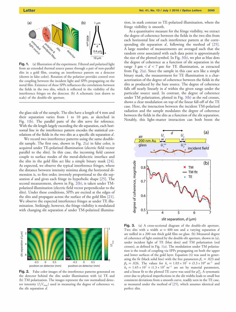
tion, in stark contrast to TE-polarized illumination, where thefringe visibility is smooth.
As a quantitative measure for the fringe visibility, we extractthe degree of coherence between the fields in the two slits fromeach horizontal line of each interference pattern at the corre-sponding slit separation d , following the method of [25].A large number of measurements are averaged such that therandom error associated with each data point is approximatelythe size of the plotted symbol. In Fig. 3(b), we plot as blue dotsthe degree of coherence as a function of slit separation in therange 3 μm < d < 7 μm for TE illumination, as extractedfrom Fig. 2(a). Since the sample in this case acts like a simplebinary mask, the measurement for TE illumination is a char-acterization of the degree of coherence between the fields in theslits as produced by the bare source. The degree of coherencefalls off nearly linearly in d within the given range under theparticular source used. In contrast, the degree of coherenceunder TM polarization, plotted in Fig. 3(b) as the red crosses,shows a clear modulation on top of the linear fall-off of the TEcase. Here, the interaction between the incident TM-polarizedradiation and the sample modulates the degree of coherencebetween the fields in the slits as a function of the slit separation.Notably, this light–matter interaction can both boost the
Fig. 1. (a) Illustration of the experiment. Filtered and polarized lightfrom an extended thermal source passes through a pair of non-parallelslits in a gold film, creating an interference pattern on a detector(shown in false color). Rotation of the polarizer provides control overthe coupling between the incident light and SPPs propagating on themetal film. Existence of these SPPs influences the correlations betweenthe fields in the two slits, which is reflected in the visibility of theinterference fringes on the detector. (b) A schematic (not drawn toscale) of the double-slit aperture.
Fig. 2. False color images of the interference patterns generated onthe detector behind the slits under illumination with (a) TE and(b) TM polarization. The images represent the raw normalized detec-tor intensity (I∕Imax) used in measuring the degree of coherence vs.the slit separation d .
Fig. 3. (a) A cross-sectional diagram of the double-slit aperture.Two slits with a width w � 400 nm and a varying separation dare milled in a 200 nm thick gold film on glass. (b) Measured degreeof coherence of light emitted by the double-slit aperture, shown in (a),under incident light of TE (blue dots) and TM polarization (redcrosses), as defined in Fig. 1(a). The modulation under TM polariza-tion is the result of coupling via SPPs propagating on both the upperand lower surfaces of the gold layer. Equation (4) was used in gener-ating the fit (black solid line) with the free parameters βt � :023 andβb � :026. The values for kt � 1.03 × 10⁷ � i3.3 × 104 m−1 andkb � 1.65 × 10⁷ � i1.3 × 105 m−1 are set by material parameters,and a linear fit to the plotted TE curve was used for μin12. A systematicerror due to physical imperfections in the slit widths leads to small butconsistent deviations from a smooth curve, readily seen in the TE case,as measured under the method of [25], which assumes identical andperfect slits.
Letter Vol. 41, No. 13 / July 1 2016 / Optics Letters 3095

degree of coherence beyond and suppress it below that of theincoming field.
The excitation of SPPs traveling on the metal surface andmediating the coupling between the slits indeed explains theobserved modulation of the degree of coherence under TMpolarization. A simple model taking into account surface wavesfully describes our measurements. Letting U 1�ω� and U 2�ω�be complex scalar fields at some positions 1 and 2, respectively,with angular frequency ω, the degree of coherence between thefields is defined by [5]
μ12�ω�≔W 12�ω�∕ffiffiffiffiffiffiffiffiffiffiffiffiffiffiffiffiffiffiffiffiffiffiffiffiffiffiffiffiffiffiffiffiW 11�ω�W 22�ω�
p; (1)
where W nm�ω�≔hU �n�ω�Um�ω�i is the cross-spectral density
(or covariance) function, � indicates a complex conjugate, andthe angle brackets indicate an ensemble average over quasi-monochromatic field realizations.
We now apply Eq. (1) to the SPP-coupled double-slit case todescribe the degree of coherence between the fields that exit theslits under knowledge of the degree of coherence of the fieldsthat enter the slits. We let U in
1 �ω� and U in2 �ω� be the fields
incident on slits 1 and 2, respectively, as sketched in Fig. 3(a),and μin12�ω� be the degree of coherence between them.Following the model of Gan et al. [11], we assume that theincident field at each slit can be separated into two parts.The first part is directly transmitted, while the second is con-verted into SPPs that travel to the other slit and scatter backinto freely propagating radiation. Further allowing for differentmaterials at the top and bottom gold interfaces, we express thefield U j (j � 1; 2), leaving slit j as
U 1 � αU in1 � αβtU in
2 eikt d � αβbU in
2 eikbd ; (2)
and
U 2 � αU in2 � αβtU in
1 eikt d � αβbU in
1 eikbd ; (3)
where α is the fraction of the incident field that couples into theslits, βt and βb are the fractions of the coupled field that areconverted to SPPs on the gold–air and the gold–glass interfaces,respectively, kt and kb are the wave numbers associated with thesurface plasmons at these interfaces, and d is the slit separation.All the parameters α; βt ; βb; kt , and kb are complex valued anddepend on ω, in general.
Assuming the incoming power spectral densities at each slitare identical, that isW in
11�ω� � W in22�ω�, we can insert Eqs. (2)
and (3) into Eq. (1). Dropping the dependence on ω, we find
μ12 �μin12 � 2Re�A� � μin�12 Bffiffiffiffiffiffiffiffiffiffiffiffiffiffiffiffiffiffiffiffiffiffiffiffiffiffiffiffiffiffiffiffiffiffiffiffiffiffiffiffiffiffiffiffiffiffiffiffiffiffiffiffiffiffiffiffiffiffiffiffiffiffiffiffiffiffiffiffiffiffiffiffiffiffiffiffiffiffiffiffiffiffiffi
�1� 2Re�μin12A � B��1� 2Re�μin�12 A � B�p ; (4)
where A≔βteidkt � βbe
idkb , B≔jβt j2eid �kt−k�t ��jβbj2eid �kb−k�b � � 2Re�β�t βbeid�kb−k�t ��, Re indicates the real part,and we have used the fact that μin21�ω� � μin�12 �ω�. We note thatin the absence of SPPs, where βt � βb � 0, Eq. (4) predicts theentering and exiting degrees of coherence to be identical.Accordingly, the measurement of the degree of coherence underTE illumination is a measurement of μin12, since no SPPs areexcited in that case. With Eq. (4), the degree of coherence be-tween the fields U 1 and U 2 can be predicted given the materialparameters, which set the propagation constants kt and kb, andthe degree of coherence between the incident fields, μin12.
The fit to the TM data, shown as the solid line in Fig. 3(b),was created using Eq. (4). The coupling strengths βt and βbwere the only fit parameters. While βt and βb vary somewhat
for different slit separations due to physical imperfections in theslits themselves, constant values provide a consistent and mean-ingful approximation. A linear fit of the measured TE curve wasinserted for μin12, and kt and kb were determined by the materialparameters for air (refractive index 1), gold (relative permittivityϵ � −13� 1i) [26], glass (refractive index 1.51), and thecenter free-space wavelength λ � 633 nm of the incident light[24]. The fit and the measured curve correspond well, indicat-ing that Eq. (4) successfully describes the degree of coherencebetween the fields exiting the slits.
To further corroborate that the observed modulation of thedegree of coherence indeed relies on the generation of SPPsmediating between the fields in the two slits, we evaporatedan optically thin layer of 5 nm of titanium (Ti) onto the goldfilm. The resulting structure is sketched in Fig. 4(a). We againmeasure the degree of coherence of the fields in the slits forboth TE polarization [blue dots in Fig. 4(b)] and TM polari-zation (red crosses). For TE polarization, the degree of coher-ence falls off linearly with slit separation d , just as for thesample without the titanium layer. For TM polarization, thedegree of coherence has a simple sinusoidal modulation in dsitting atop the linearly sloped incoming coherence function.The modulation of the degree of coherence as a function ofslit separation d for TM illumination is markedly different inthe sample after addition of the titanium layer [Fig. 4(b)] ascompared to that before adding the titanium layer [Fig 3(b)].
Fig. 4. (a) A cross-sectional diagram of the double-slit apertureafter being covered with an optically thin (5 nm) layer of titanium.The titanium layer serves to damp SPPs on the top gold surface.(b) The measured degree of coherence of light emitted by the double-slit aperture shown in (a), under incident light of TE (blue dots) andTM polarization (red crosses). Here, the modulation under TM polari-zation is the result of coupling via SPPs propagating on only thelower surface of the gold layer. Equation (4) was used to calculatethe expected curve (solid black line) with βt set to zero to accountfor the absence of SPPs on the top gold surface, βb as extracted fromthe fit in Fig. 3(b), kb set by the material parameters, and inserting alinear fit of the plotted TE curve for μin12. The systematic error men-tioned in Fig. 3 also affects these measurements.
3096 Vol. 41, No. 13 / July 1 2016 / Optics Letters Letter

In the absence of the titanium layer, SPPs propagate on bothsurfaces of the gold layer with different propagation constants,leading to the beat pattern observed in Fig. 3(b). Addition ofthe titanium layer causes the SPPs propagating on the topinterface to be highly damped such that plasmonic couplingoccurs only on the gold–glass interface. Since only one SPPwavelength is present, the degree of coherence has a simplesinusoidal modulation in d under TM polarization. Ignoringdamping, Eq. (4) predicts this modulation to have a wavelengthequal to the SPP wavelength of 2π∕Re�kb� � 381 nm. Asshown in Fig. 4(b), the period of modulation is indeed theSPP wavelength, as indicated by the two vertical dashed lines.We stress that the solid line in Fig. 4(b) is not a fit but a cal-culation according to Eq. (4) with all parameters deduced fromindependent measurements: the value for μin12 was extractedfrom a linear fit to the measured curve under TE illumination,the value for kb is set by material parameters (and identical tothat used in the case without titanium layer), βb is the fitparameter obtained from the sample without titanium layer,and βt is set to zero, accounting for the absence of SPPs propa-gating at the top surface of the gold film. We note that althoughthe modulation depth appears to be constant in both Figs. 3(b)and 4(b), the finite propagation length of the SPPs eventuallycauses the modulation depth to decrease with increasing d . Theexpected and measured TM curves are in excellent agreement,indicating that our simple model successfully accounts for allsignificant physical mechanisms at play.
Our experimental results clearly demonstrate that surfaceplasmon polaritons modulate the statistical correlation, alsoknown as the spectral degree of spatial coherence, betweenthe light fields emitted by a double-slit aperture [23]. Ourmethod allows for a controllable increase in the degree of co-herence beyond that of the incoming light, and for a reductionin the degree of coherence below that of the incoming light, bychanging the separation between the slits. By choosing themetal, illumination wavelength, and slit width, the modulationdepth of the degree of coherence between the fields in the twoslits can be engineered [27]. Spatial coherence modulation is ofconsiderable interest for applications in optical free-space com-munications, where partially spatially coherent beams might bemore robust against atmospheric or undersea turbulence thancoherent beams [28]. More generally, the spatial coherence of abeam determines how it propagates through space [29], and theability to modulate the coherence of a beam at high speed canserve as a powerful tool for controlling electromagnetic radia-tion. Current methods of dynamically controlling spatial coher-ence rely on devices such as SLMs or DMDs, whose switchingspeeds forbid any high-speed application. The nanophotonicmethod described here is fundamentally different, and whencombined with dynamic SPP control methods [30] will enableintegrated spatial coherence switching at extremely high rates.
Funding. Swiss National Science Foundation (SNSF)(200021_149433); Air Force Office of Scientific Research(AFOSR) (FA9550-16-1-0119).
Acknowledgment. The authors acknowledge NickVamivakas, Miguel Alonso, and Dieter Pohl for fruitfuldiscussions.
REFERENCES
1. T. Young, A Course of Lectures on Natural Philosophy and theMechanical Arts (J. Johnson, 1807), Vol. 1, pp. 464–465.
2. M. Born and E. Wolf, Principles of Optics, 7th ed. (CambridgeUniversity, 1999).
3. C. Jönsson, Z. Phys. 161, 454 (1961).4. M. Arndt, O. Nairz, J. Vos-Andreae, C. Keller, G. van der Zouw, and A.
Zeilinger, Nature 401, 680 (1999).5. E. Wolf, Introduction to the Theory of Coherence and Polarization of
Light (Cambridge University, 2007).6. J. W. Goodman, Statistical Optics (Wiley, 2015).7. E. Collett and E. Wolf, Opt. Lett. 2, 27 (1978).8. P. D. Santis, F. Gori, G. Guattari, and C. Palma, Opt. Commun. 29,
256 (1979).9. M. W. Hyde, S. Basu, D. G. Voelz, and X. Xiao, J. Appl. Phys. 118,
093102 (2015).10. B. Rodenburg, M. Mirhosseini, O. S. M. na Loaiza, and R. W. Boyd,
J. Opt. Soc. Am. B 31, A51 (2014).11. C. H. Gan, G. Gbur, and T. D. Visser, Phys. Rev. Lett. 98, 043908
(2007).12. C. H. Gan and G. Gbur, Plasmonics 3, 111 (2008).13. C. H. Gan, Y. Gu, T. D. Visser, and G. Gbur, Plasmonics 7, 313
(2012).14. T.-T. Bian, B.-Y. Gu, and Y. Zhang, Opt. Commun. 283, 608 (2010).15. B. Kanseri, H. C. Kandpal, and R. C. Budhani, Opt. Commun. 285,
4811 (2012).16. T. Saastamoinen and H. Lajunen, Opt. Lett. 38, 5000 (2013).17. N. Kuzmin, G. W. ’t Hooft, E. R. Eliel, G. Gbur, H. F. Schouten, and
T. D. Visser, Opt. Lett. 32, 445 (2007).18. S. Ravets, J. C. Rodier, B. E. Kim, J. P. Hugonin, L. Jacubowiez, and
P. Lalanne, J. Opt. Soc. Am. B 26, B28 (2009).19. S. Aberra Guebrou, C. Symonds, E. Homeyer, J. C. Plenet, Y. N.
Gartstein, V. M. Agranovich, and J. Bellessa, Phys. Rev. Lett. 108,066401 (2012).
20. L. Shi, T. K. Hakala, H. T. Rekola, J.-P. Martikainen, R. J. Moerland,and P. Törmä, Phys. Rev. Lett. 112, 153002 (2014).
21. H. F. Schouten, N. Kuzmin, G. Dubois, T. D. Visser, G. Gbur, P. F. A.Alkemade, H. Blok, G. W. ’t Hooft, D. Lenstra, and E. R. Eliel, Phys.Rev. Lett. 94, 053901 (2005).
22. T. Wang, G. Comtet, E. L. Moal, G. Dujardin, A. Drezet, S. Huant, andE. Boer-Duchemin, Opt. Lett. 39, 6679 (2014).
23. R. Carminati and J.-J. Greffet, Phys. Rev. Lett. 82, 1660 (1999).24. S. A. Maier, Plasmonics: Fundamentals and Applications (Springer,
2007).25. S. Divitt, Z. J. Lapin, and L. Novotny, Opt. Express 22, 8277 (2014).26. K. M. McPeak, S. V. Jayanti, S. J. P. Kress, S. Meyer, S. Iotti, A.
Rossinelli, and D. J. Norris, ACS Photon. 2, 326 (2015).27. J. Renger, S. Grafström, and L. M. Eng, Phys. Rev. B 76, 045431
(2007).28. G. Gbur, J. Opt. Soc. Am. A 31, 2038 (2014).29. L. Mandel and E. Wolf, Optical Coherence and Quantum Optics
(Cambridge University, 1995).30. D. Pacifici, H. J. Lezec, and H. A. Atwater, Nat. Photonics 1, 402
(2007).
Letter Vol. 41, No. 13 / July 1 2016 / Optics Letters 3097