module (03) arc breaking technologies and current interrupt
DESCRIPTION
sTRANSCRIPT

LV , MV & HV Switchgear
Module (03) Arc Breaking Technologies and Current Interruption Page 1 of 22
Module
03 Arc Breaking Technologies
and Current Interruption
LV , MV & HV Switchgear
Module (03) Arc Breaking Technologies and Current Interruption Page 2 of 22
3.1 INTRODUCTION
The circuit‐breakers, as they have been defined earlier in chapter 1, are automatic switches which can interrupt fault
currents. In some applications, like single phase traction systems, single‐pole circuit‐breakers are used. The part of the
circuit‐breaker connected in one phase is called the "pole". The circuit‐breaker suitable for three phase system is
called a triple‐pole circuit‐breaker. Each pole, of the circuit‐breaker, comprises one or more "interrupters" or "arc‐
extinguishing chambers". The interrupter encloses a set of "fixed and moving contacts". The moving contacts can be
drawn apart by means of the operating links of an operating mechanism.
The electric arc, produced by the separation of current carrying contacts, is a type of electric discharge between
electrodes. In circuit‐breakers, the arc persists during the brief period after separation of current carrying contacts.
The circuit‐breaker should be capable of extinguishing the arc without getting damaged. The arc is interrupted by a
suitable medium and by adopting suitable technique for arc extinction. The circuit‐breakers can be classified on the
basis of arc extinction medium.
The arc plays an important role in the behavior of the circuit breaker. The interruption of d.c. arcs is relatively more
difficult than a.c. arcs. In a.c. arcs, as the current becomes zero during the regular wave, the arc vanishes and it is
prevented from re‐striking. Circuit‐breakers employ various techniques to extinguish the arc resulting from the
separation of the current carrying contacts. The mode of arc extinction is either "high resistance interruption" or
"zero‐point interruption". High Resistance Interruption: In this process, the resistance of the arc is increased by
lengthening and cooling it to such an extent that the system voltage is no longer able to maintain the arc and the arc
gets extinguished. This technique is employed in air break circuit‐breakers and d.c. circuit‐breakers.
Low Resistance or Zero‐point Interruption: In this process, the arc gets extinguished at natural current zero, of the
alternating current wave, and is prevented from restriking again by rapid build‐up of dielectric strength of the contact
space. This process is employed in almost all a.c. circuit‐breakers. The theory and manner in which the various types of
circuit breaker and contactor extinguish the arc and interrupt the current is dealt with in the following.
3.2 BREAKING TECHNOLOGIES IN BRIEF
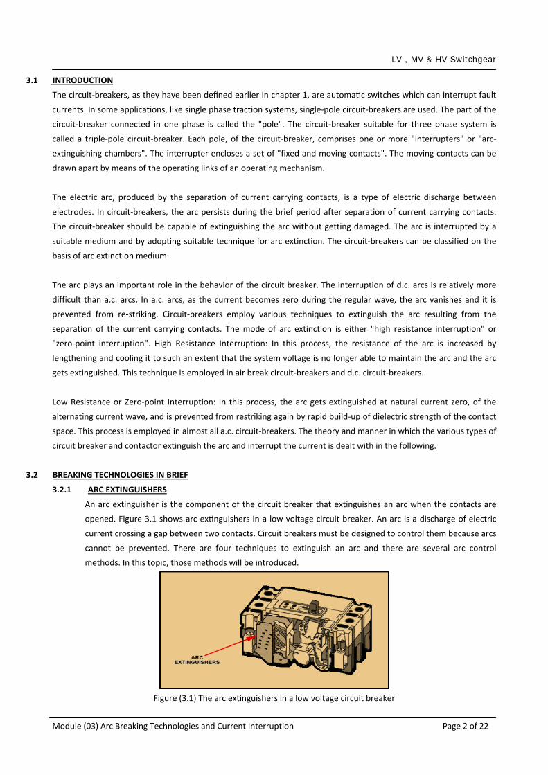
3.2.1 ARC EXTINGUISHERS
An arc extinguisher is the component of the circuit breaker that extinguishes an arc when the contacts are
opened. Figure 3.1 shows arc extinguishers in a low voltage circuit breaker. An arc is a discharge of electric
current crossing a gap between two contacts. Circuit breakers must be designed to control them because arcs
cannot be prevented. There are four techniques to extinguish an arc and there are several arc control
methods. In this topic, those methods will be introduced.
Figure (3.1) The arc extinguishers in a low voltage circuit breaker

LV , MV & HV Switchgear
Module (03) Arc Breaking Technologies and Current Interruption Page 3 of 22
3.2.2 WHAT IS AN ARC?
Do you ever recall pulling a plug from a wall socket (Fig. 3.2) and seeing what appeared to be sparks? What
you were observing, on a very small scale, was an attempt at arc formation between the wall contacts and
the plug contacts in your hand. For the sake of this discussion, let’s define an arc as a discharge of electric
current crossing a gap between two contacts.
Figure (3.2) Typical ARC
Arcs are formed when the contacts of a circuit breaker are opened under a load. Arcs can be very destructive and vary
greatly in size and intensity. The size of the arc depends on the amount of current present when the contacts are
pulled apart. For example, an arc that forms when normal load current is broken is insignificant compared to the arc
that forms when a short circuit is broken. Because arcs cannot be prevented, circuit breakers must be designed to
control them.
The heat associated with an arc creates an ionized gas environment. The more ionization, the better the conditions
are for an arc to be maintained and grow. The bigger the arc, the more heat created, which increases ionization.
Arcing is a condition that must be dealt with quickly and effectively by a circuit breaker.
The important thing to remember here is that the ability of the circuit breaker to control the arc is the key to its short
circuit interrupting capability. This is a critical factor for selecting circuit breakers. A short circuit is the most
devastating over‐current condition.
Current Zero or Zero Point is a very important aspect to arc extinguishing. At current zero, conditions are optimal for
preventing an arc from continuing. The current is said to be “Current Zero” when the sine curve is at 0°, 180° and 360°
(Fig. 3.3).
Figure (3.3) Current Zero
Voltage is also a very important consideration because it is the pressure that keeps the current moving. Left
unchecked, voltage will keep pushing the current through current zero and give new life to the arc. Voltage does not
take kindly to being stopped in its tracks during the extinguishing of an arc. If it reignites, it can damage the whole
electrical system.

LV , MV & HV Switchgear
Module (03) Arc Breaking Technologies and Current Interruption Page 4 of 22
Circuit breakers take this process into account by simultaneously opening the contacts and extinguishing the arc. The
successful extinguishing of the arc depends on the Dielectric Strength of the gap between the contacts. The dielectric
strength is the maximum voltage a dielectric can withstand without breaking down. A Dielectric is any insulating
material between two conductors. In these discussions, the circuit breaker contacts are the conductors and the
insulating material can be air, gas or a vacuum. If the dielectric strength is greater than the voltage trying to re‐ignite
the arc, the arc extinguishing will be successful.
The invention of a device called DE‐ION® arc extinguisher in the early 1900s by Westinghouse was a revolutionary
advance in arc interruption. Improved versions were used for years with a majority of circuit breakers and continue to
be used today with low voltage circuit breakers.
A number of other approaches to arc control have also been tried. One of the success stories is the use of Vacuum
Interruption with medium voltage breakers.
3.2.3 ARC CONTROL TECHNIQUES
Each approach has made improvements to its initial concept in an effort to extinguish arcs more efficiently. Arc
control methods utilize one or more of the following general techniques:
Stretching Arc: The arc is produced when the contacts part. As the gap widens, the arc is stretched (Fig. 3.4)
and cooled to the point where it is extinguished.
Figure (3.4) Stretching ARC
Breaking Arc into Smaller Pieces: The arc is produced when the contacts part. The arc moves up into the arc
divider and splits (Fig. 3.5), cools and is extinguished.
Figure (3.5) Breaking ARC
Blowing Out Arc: In this method, a high‐pressure gas blows the arc into an arc divider to be extinguished (Fig. 3.6).
Figure (3.6) Blowing out arc

LV , MV & HV Switchgear
Module (03) Arc Breaking Technologies and Current Interruption Page 5 of 22
Enclosing Contacts: In this method, the contacts are housed in an oxygen‐free enclosure (Fig. 3.7) with a dielectric
such as a vacuum, gas or cooling oil. Without oxygen, the arc cannot sustain itself and the arc is extinguished.
Figure (3.7) Enclosing contacts
3.2.4 ARC CONTROL METHODS
There are six methods used around the world today to deal with arc control, arc chute, vacuum interrupter, SF6
minimum oil, magnetic coil, Puffer
The arc chute method: only uses the Breaking Arc into Smaller Pieces technique. Arc chutes are normally
associated with low voltage circuit breakers due to efficiency and cost. In general, an arc chute will confine,
divide and cool an arc (Fig. 3.8), resulting in the arc being unable to sustain itself. There is one arc chute for
each set of contacts.
Figure (3.8) Arc chute method
The vacuum interrupter: method uses the Enclosing Contacts technique to extinguish arcs. The vacuum enables
the contacts to be smaller and eliminates the divider, making this method the most cost effective and efficient
above 1000V. Arcing takes place within a sealed evacuated enclosure (Fig. 3.9). The contacts are located inside
and arcing occurs when the contacts are separated. Because the environment inside the interrupter envelope
is a vacuum, an arc cannot be easily sustained. It will not reach the intensity possible with an arc chute. One
vacuum interrupter is provided for each set of contacts.
Figure (3.9) Vacuum interrupter method

LV , MV & HV Switchgear
Module (03) Arc Breaking Technologies and Current Interruption Page 6 of 22
The SF6 method: also uses the Enclosing Contacts technique. It was a precursor to the vacuum interrupter and
used SF6 gas as the dielectric (Fig. 3.10). The heat energy created by the arc works to break apart the SF6
molecules . The larger the arc, the greater the breakdown of the gas which aids in extinguishing the arc .
Figure (3.10) SF6 method
The minimum oil method: also uses Enclosing Contacts with oil as the dielectric (Fig. 3.11). The arc energy is
absorbed as it rips hydrogen away from the oil molecule. The oil itself also helps to cool the arc. As current zero
is approached, more oil is drawn into the system, further cooling and Deionizing the arc. It is used today in low
voltage situations and potentially explosive environments where an arc chute is not desirable.
Figure (3.11) Minimum oil method
The magnetic coil method: uses the Breaking Arc into Smaller Pieces technique. It is very similar to the arc
chute method. The natural movement of an arc is upward, in this instance, into an arc chute. A coil, called a
blowout coil, is located in the centre of the arc chute (Fig. 3.12). The arc is broken into two. The arcs are
lengthened and cooled as they rise higher. The cooling reduces the rate of ionization. When the ionization
drops below the level necessary to sustain the arcs, they extinguish at current zero. Prior to vacuum interrupter
technology becoming the method of choice with medium voltage power breakers for extinguishing arcs, the
magnetic coil method served well for many years.

LV , MV & HV Switchgear
Module (03) Arc Breaking Technologies and Current Interruption Page 7 of 22
Arc runners
Arc splitters
Elongated arc
Arc in process of travelling
Blowout coils
Origin of arc
Figure (3.12) Magnetic blowout coil
The puffer method: uses the Blowing Out Arc and Enclosing Contacts techniques. It uses SF6 gas as the
dielectric. It is the most efficient and cost effective method above 38 kV. This type interrupter is basically a pair
of separable contacts, a piston and a cylinder, mounted in a reservoir of gas (Fig. 3.13). As the contacts part,
the piston moves up to drive the gas through the arc to interrupt it. It also utilizes coils and takes advantage of
natural magnetic affects to create a force sufficient to extinguish the arc.
Figure (3.13) Puffer method Current Interruption in A.C. Circuit‐Breakers
3.3 INTRODUCTION TO CURRENT INTERRUPTION IN AC CIRCUIT BREAKERS
The waveforms of the current and the voltage during the arc interruption process will be studied in this chapter. This
description applies to the circuit‐breakers employing the principle of zero‐point interruption. Every a.c. circuit‐breaker
generally adopts the zero‐point interruption technique. Consider a circuit‐breaker connected to a generator on no
load at rated terminal voltage. The circuit‐breaker is in open position and the other side of circuit‐breaker is short
circuited (Fig. 3.14).
Figure (3.14) Alternator circuit breaker closing on 3‐phase short circuit.

LV , MV & HV Switchgear
Module (03) Arc Breaking Technologies and Current Interruption Page 8 of 22
Let the circuit‐breaker be closed at the instant when voltage of terminal B w.r.t. neutral is zero. In such a case the
short circuit current in phase B will have maximum d.c. component and the waveform of current will be
unsymmetrical about normal zero axis as shown in Fig. 3.15.
The figure shows the typical waveform of short circuit current in a phase having maximum d.c. component. The
generator is on no load before t = 0. Hence the current is zero before t = 0. At t = 0, the short circuit is applied and the
current increases to a high value during the first quarter cycle. The peak of the first major current loop (shown dotted)
is OM and this is the maximum instantaneous value of current during the short‐circuit. This instantaneous peak value
of the first major current loop is called the Making current. In the figure the making current is OM. We will come back
to this making current after covering the remaining process.
The circuit‐breaker contacts separate after a few cycles since the relay and the operating mechanism takes at least a
couple of cycles. Let us assume that the circuit‐breaker contacts separate at t = T1. The r.m.s. value of short circuit
current at the instant of contact separation is termed as Breaking current.
Figure (3.15) Oscillogram of current and voltage during fault‐clearing.
After the separation of contacts of the circuit‐breaker, an arc is drawn between the contacts. The arc current varies
sinusoidally for a few cycles. At t = T2, a particular current zero, the dielectric strength of arc space builds up
sufficiently so as to prevent the continuation of arc. At the current zero, this arc is extinguished and is interrupted.
Meanwhile what is happening to the voltage between contacts? This voltage is recorded in Fig. 3.15. Before t = 0, the
contacts are closed and the voltage between them is zero. After the separation of the contact (t = T1), the voltage
across contact increases, in fact this voltage is the voltage drop across the arc during the arcing period. The voltage
across arc is in phase with current since the arc is resistive. The peculiar waveform shape is a result of volt‐ampere
characteristic of arc‐discharge. During subsequent half cycles, the voltages across contact increases due to increased
arc resistance. Finally at t = T2, when arc gets extinguished, a high frequency voltage transient appears across the
contacts which is superimposed on power frequency system voltage. This high frequency transient voltage tries to re‐
strike the arc. Hence it is called Restriking Voltages or Transient Recovery Voltage (TRV). The restriking voltage is
LV , MV & HV Switchgear
Module (03) Arc Breaking Technologies and Current Interruption Page 9 of 22
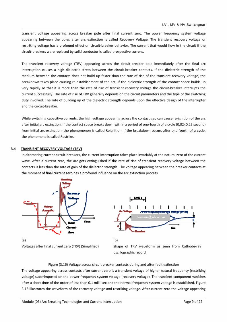
transient voltage appearing across breaker pole after final current zero. The power frequency system voltage
appearing between the poles after arc extinction is called Recovery Voltage. The transient recovery voltage or
restriking voltage has a profound effect on circuit‐breaker behavior. The current that would flow in the circuit if the
circuit‐breakers were replaced by solid conductor is called prospective current.
The transient recovery voltage (TRV) appearing across the circuit‐breaker pole immediately after the final arc
interruption causes a high dielectric stress between the circuit‐breaker contacts. If the dielectric strength of the
medium between the contacts does not build up faster than the rate of rise of the transient recovery voltage, the
breakdown takes place causing re‐establishment of the arc. If the dielectric strength of the contact‐space builds up
very rapidly so that it is more than the rate of rise of transient recovery voltage the circuit‐breaker interrupts the
current successfully. The rate of rise of TRV generally depends on the circuit parameters and the type of the switching
duty involved. The rate of building up of the dielectric strength depends upon the effective design of the interrupter
and the circuit‐breaker.
While switching capacitive currents, the high voltage appearing across the contact gap can cause re‐ignition of the arc
after initial arc extinction. If the contact space breaks down within a period of one‐fourth of a cycle (0.02×0.25 second)
from initial arc extinction, the phenomenon is called Reignition. If the breakdown occurs after one‐fourth of a cycle,
the phenomena is called Restrike.
3.4 TRANSIENT RECOVERY VOLTAGE (TRV)
In alternating current circuit‐breakers, the current interruption takes place invariably at the natural zero of the current
wave. After a current zero, the arc gets extinguished if the rate of rise of transient recovery voltage between the
contacts is less than the rate of gain of the dielectric strength. The voltage appearing between the breaker contacts at
the moment of final current zero has a profound influence on the arc extinction process.
(a) (b)
Voltages after final current zero (TRV) (Simplified) Shape of TRV waveform as seen from Cathode‐ray
oscillographic record
Figure (3.16) Voltage across circuit breaker contacts during and after fault extinction
The voltage appearing across contacts after current zero is a transient voltage of higher natural frequency (restriking
voltage) superimposed on the power frequency system voltage (recovery voltage). The transient component vanishes
after a short time of the order of less than 0.1 milli‐sec and the normal frequency system voltage is established. Figure
3.16 illustrates the waveform of the recovery voltage and restriking voltage. After current zero the voltage appearing

LV , MV & HV Switchgear
Module (03) Arc Breaking Technologies and Current Interruption Page 10 of 22
across the contacts is composed of transient restriking voltage and power frequency recovery voltage. Recovery
voltage is the voltage which appears across the terminals of a pole of a circuit‐breaker after the breaking of current. It
refers to the breaker‐pole first to clear, while the transient recovery (TRV) or Restriking Voltage is the recovery voltage
during the time in which it has a significant transient character. TRV lasts for a few tens or hundreds of microseconds
(Fig. 3.16b). It may be oscillatory or non‐oscillatory or a combination, depending upon the characteristics of the circuit
and the circuit‐breaker. It is the voltage across the first pole to clear. The same is generally higher than across the two
poles which clear later.
Power Frequency Recovery Voltage is the recovery voltage of power frequency (50 Hz.) appearing after the transient
voltage has been subsided. The Transient Recovery Voltage refers to the voltage across the pole immediately after arc
extinction. Such voltage has a power‐frequency component plus an oscillatory transient component. The oscillatory
transient component is due to the inductance and capacitance in the circuit. The power frequency component is due
to the system voltage (Fig. 3.16). The transient oscillatory component subsides after a few micro‐seconds and the
power frequency component continues. The frequency of transient component is given by
Hz2
1LC
fn π=
where fn = frequency of transient recovery voltage, Hz
L = equivalent inductance, Henry
C = equivalent capacitance, Farad.
In actual systems the waveform of the transient recovery voltage has several component frequencies ranging from a
few hertz to several thousand hertz, depending upon the values of the circuit parameters.
3.4.1 EFFECT OF NATURAL FREQUENCY OF TRV
Figure 3.17 illustrates the slopes of tangents to three TRV waveforms of different frequencies (fn , f2n , f4n).
With increase in the natural frequency, the rate of rise of TRV (RRRV) at current zero increases.

LV , MV & HV Switchgear
Module (03) Arc Breaking Technologies and Current Interruption Page 11 of 22
Figure (3.17) Effect of frequency of TRV on the RRRV
The rate of rise of transient recovery voltage across circuit‐breaker pole causes voltage stress on the contact‐
gap tending to continue the arc. With higher frequency (say f4n), relatively less time is available for the
building of dielectric strength of the contact gap. Hence higher frequency is associated with greater stresses.
The breaking capacity of a circuit‐breaker (r.m.s. value of current, which the circuit‐breaker can interrupt) is
related with the rate if rise TRV and, therefore, natural frequency of TRV. The breaking capacity reduces with
increase in natural frequency.
3.4.2 EFFECT OF POWER‐FACTOR ON TRV
The voltage appearing across the circuit‐breaker pole at the instant of final current zero is influenced by the
power‐factor of the current (Fig. 3.18). The arc gets extinguished at current zero. The power‐frequency
voltage appears across the circuit‐breaker pole. The instantaneous value of the voltage at the instant of
current zero depends upon the phase angle between current and voltage. For unity power‐factor loads, the
voltage and current are in phase and both are zero at the same instant (Fig. 3.18a). For zero power‐factor
currents, the peak of the voltage (emax) is impressed on the circuit‐breaker pole at the instant of current
zero. Such sudden application of voltage gives rise to severe transient and has a high rate of rise of TRV (Fig.
3.18b). Hence interrupting currents of low power‐factor is a difficult switching duty.
3.4.3 EFFECT OF REACTANCE‐DROP ON POWER‐FREQUENCY RECOVERY VOLTAGE
Suppose V1 is voltage at the location of the circuit‐breaker before fault. During the fault the increased current
cause an increase in the voltage drop in the reactance. As a result the voltage appearing at the location of the
fault, immediately after fault clearance say V2 is slightly less than V1. It takes some time for the system
voltage to regain the original value V1. Hence the power frequency recovery voltage is slightly less than the
normal power frequency system voltage.
(a) Unity power factor: e0 at i0 (b) Zero power factor: emax at i0
Figure (3.18) Effect of power factor on instantaneous value of voltage at current zero.

LV , MV & HV Switchgear
Module (03) Arc Breaking Technologies and Current Interruption Page 12 of 22
3.4.4 EFFECT OF ARMATURE REACTION ON RECOVERY VOLTAGE
The short‐circuit currents are at lagging power factor and, therefore, have a demagnetizing armature reaction
in alternators. As a result, the induced e.m.f. of alternators reduces during short‐circuit currents. The e.m.f
requires some time to regain its original value. Hence the power frequency component of recovery voltage is
slightly less than the normal value of system voltage.
3.4.5 EFFECT OF THE FIRST‐POLE‐TO‐CLEAR
Refer to Figure 3.19 illustrating a three phase fault not involving the earth. The voltage across the circuit‐
breaker pole, first to clear is 1.5 times the phase voltage. In three‐pole circuit‐breakers, arc extinction in the
three poles is not simultaneous as currents in three phases are mutually 120o out‐of‐phase. Hence, the
power‐frequency recovery voltage of the phase in which the arc gets extinguished first, is about 1.5 times the
phase voltage. In practice the recovery voltage of the pole, first‐to‐extinguish the arc is of the order of 1.2 to
1.5 times. If the neutral is grounded through reactor and if the fault involves earth, the recovery voltage at
the location of the circuit‐breaker is influenced by the equivalent system reactances and can be calculated by
the method of symmetrical components.
3.4.6 THE FIRST‐POLE‐TO‐CLEAR FACTOR
To consider the effect of the first‐pole‐clear on the power frequency component of the recovery voltage, the
following factor has been defined in the standards on high voltage a.c. circuit breakers.
The first pole to clear factor is defined as
removedfault with voltageneutral toPhasephasefaulty & phasehealthy between voltageRMSfactorclear -to-pole-first The =
at the location of the circuit‐breaker during a phase ‐to‐phase fault. Referring to Fig. 3.20, first‐pole‐to‐clear factor is
the ratio RN
RY
VV
at the location of the circuit‐breaker for a phase‐to‐phase fault.
Figure (3.19) Voltage across the phase, first‐to‐open .

LV , MV & HV Switchgear
Module (03) Arc Breaking Technologies and Current Interruption Page 13 of 22
Figure (3.20) Explaining the first‐pale‐to clear factor (VRY/VRN)
3.5 SINGLE FREQUENCY TRANSIENT
The single frequency restriking voltage transient is produced in the circuit illustrated in Fig. 3.21b. Frequency of
oscillation is given by the natural frequency of the circuit, i.e. Hz
LCfn π2
1=
where L = inductance, Henry
C = capacitance, Farads.
These frequencies are of the order of 10 to 10,000 Hz depending upon the value of L and C. The actual power system
is composed of distributed capacitance and inductances. The circuit configuration is also complex. The TRV for such
circuits can have several component frequencies ranging from a few Hertz to several kilohertz. A typical single
frequency transient is illustrated in Fig. 3.21a. Such a transient is obtained while opening on a terminal fault. In such
cases the reactance between the fault and the circuit‐breaker is negligible.

LV , MV & HV Switchgear
Module (03) Arc Breaking Technologies and Current Interruption Page 14 of 22
(a) waveform (b) Circuit
Figure (3.21) Explaining single frequency transient of TRV.
3.6 DOUBLE FREQUENCY TRANSIENTS
The circuit may have L and C on both sides of the circuit‐breaker as shown in Fig. 3.22a. Before clearing the fault, both
terminals 1 and 2 are at the same potential. After arc extinction both circuits oscillate at their own natural frequencies
and a composite double frequency transient appears across the circuit breaker pole (Fig. 3.22b). In general the
frequencies and waveform, rate of rise and peak value of the TRV depends upon, several aspects such as:
network configuration
type of fault
type of neutral earthing
(a) circuit (b) waveform
Figure (3.22) Double frequency transient of TRV .
The TRV wave can be defined by various methods such as
specifying the peak and time to reach the peak.
specifying the TRV wave by defining the segment of lines which enclose the TRV waveform.
The latter method has been now universally adopted.
3.7 RATE OF RISE OF TRV
The rate of rise of restriking voltage usually abbreviated by R.R.R.V. is a rate expressed in Volts per micro‐second,
represents the rate of increase in restriking voltage. The rate of rise of Transient Recovery Voltage (TRV) and the
natural frequency of TRV are closely associated. The rate of the rise of TRV depends on the system parameters. The
circuit breaker should be capable of interrupting its rated short‐circuit breaking current under the specified conditions
of TRV. Hence the following characteristics of TRV are significant:
LV , MV & HV Switchgear
Module (03) Arc Breaking Technologies and Current Interruption Page 15 of 22
• Peak of TRV, time to reach the peak. Hence the rate of rise of TRV
• Frequency of TRV • Initial rate of rise
The term rate of rise of restriking voltage is explained as follows. If e is the restriking voltage,
secvolts.... −= μ
dtdeVRRR
where t is in micro‐seconds and e is in volts.
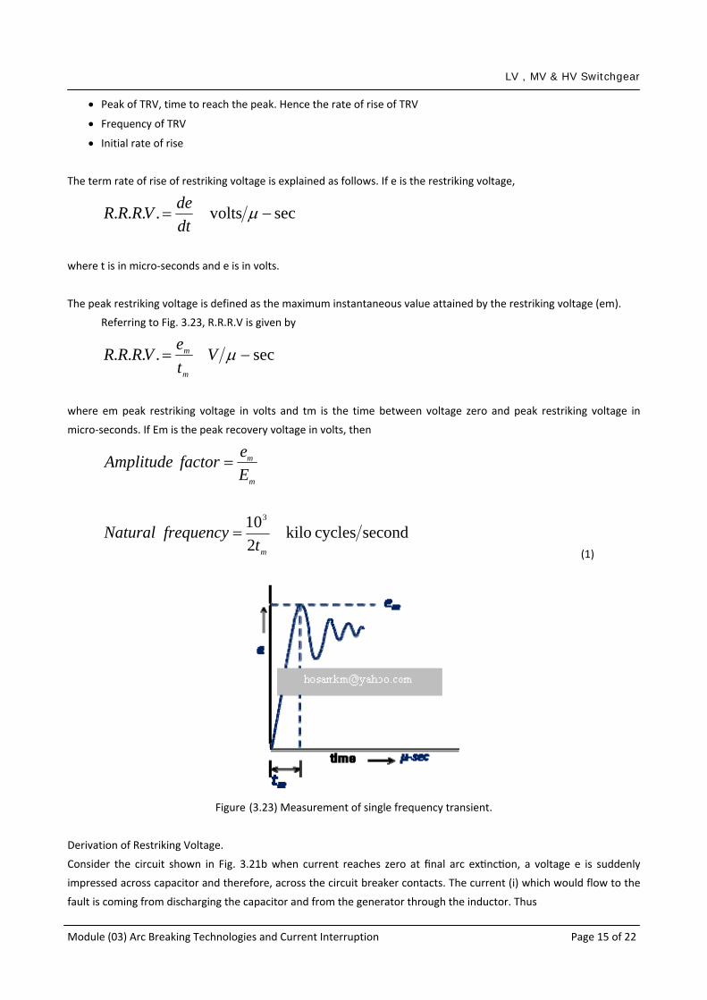
The peak restriking voltage is defined as the maximum instantaneous value attained by the restriking voltage (em).
Referring to Fig. 3.23, R.R.R.V is given by
sec.... −= μVteVRRR
m
m
where em peak restriking voltage in volts and tm is the time between voltage zero and peak restriking voltage in
micro‐seconds. If Em is the peak recovery voltage in volts, then
m
m
EefactorAmplitude =
secondcycles kilo2103
mtfrequencyNatural =
(1)
Figure (3.23) Measurement of single frequency transient.
Derivation of Restriking Voltage.
Consider the circuit shown in Fig. 3.21b when current reaches zero at final arc extinction, a voltage e is suddenly
impressed across capacitor and therefore, across the circuit breaker contacts. The current (i) which would flow to the
fault is coming from discharging the capacitor and from the generator through the inductor. Thus

LV , MV & HV Switchgear
Module (03) Arc Breaking Technologies and Current Interruption Page 16 of 22
dtdeCedt
Li
iii CL
+=
+=
∫1
2
2
dtedC
Le
dtdi
+= (2)
Assuming zero time at zero currents, and further e = Emcos(�t) and ( )t
LEi m ωω
sin= before opening of circuit
breaker,
( )t
LE
dtdi m ωω
ωcos=
At t = 0, LE
dtdi m=
Substituting in Eq. (2), we get
2
2
dtedC
Le
LEm +=
(3)
The solution of this standard equation is
⎟⎠⎞
⎜⎝⎛ −=
LCtEe m cos1
(4)
This is an expression for restriking voltage in which
Em is the peak value of recovery voltage in Volts, phase to neutral
t = time in seconds
L = inductance in Henrys
C = capacitance in Farads
e = restriking voltage in Volts.
Note, Rate of rise of restriking voltage
LCt
LCE
dtde m sin=
(5)
R.R.R.V is maximum when its derivative is zero,
i.e. ;0 when maximum is
2
2
=dt
eddtde

LV , MV & HV Switchgear
Module (03) Arc Breaking Technologies and Current Interruption Page 17 of 22
0cos =LCt
LCEm
or when
2π
=LCt
; i.e.
LCt
2π
=
The maximum R.R.R.V is the value of de/dt at LCt
2π
=
R.R.R.V.max = LCEm
(6)
Further, peak restriking voltage occurs when e is maximum, i.e. when wheni.e. ;0 =
dtde
π=LCt
; i.e.
LCt π=
and peaking restriking voltage is equal to
( ) mm EEe 2cos1 =−= π
(7)
SUMMARY OF EXPRESSIONS
⎟⎠⎞
⎜⎝⎛ −=
LCtEe m cos1
(8)
LCt
LCEVRRR m sin.... =
(9)
π==LCtEe m at2max
(10)
LCtLCEVRRR m
2at.... max
π==
(11)
LCfn π2
1=
(12)

LV , MV & HV Switchgear
Module (03) Arc Breaking Technologies and Current Interruption Page 18 of 22
It is observed from Eqs. 11 and 12 that
R.R.R.V.max = 2π Em fn (13)
The Maximum Rate of Rise of Restriking voltage is proportional to the natural frequency of the circuit. This is an
important conclusion. The circuit with high natural frequency gives a high rate of TRV and produces severe dielectric
stress on the contact space of the circuit‐breaker. Hence
High fn → High rate of rise of TRV
Examples on Restriking Voltage
Example 1: A 50‐Hz, 3‐phase alternator with grounded neutral has inductance of 1.6 mH per phase and is connected
to busbar through a circuit‐breaker. The capacitance to earth between the alternator and the circuit‐breaker is 0.003
μF per phase. The circuit breaker opens when r.m.s. value of current is 7500 A. Determined analytically the following:
Maximum rate of rise of restriking voltage.
Time for maximum rate of rise of restriking voltage.
Frequency of oscillations.
Neglect first‐pole‐to‐clear factor.
Solution:
Frequency of oscillation is given by
LCfn π2
1=
Hz7264410003.0106.12
163=
×××=∴
−−πnf
The recovery voltage can be calculated from the known values of current i and ωL
E = i×ωL = i×2πf×L
= 7500×314×1.6×10‐3 = 3768 volts‐rms
Em = √2×Erms = √2×3768 = 5329 volts
Expression for restriking voltage is
⎟⎠⎞
⎜⎝⎛
×−=
⎟⎠
⎞⎜⎝
⎛×××
−=
⎟⎠⎞
⎜⎝⎛ −=
−
−−
6
63
102.2cos15329
10003.0106.1cos15329
cos1
t
tLCtEe m
where e is in volts and t is in sec.

LV , MV & HV Switchgear
Module (03) Arc Breaking Technologies and Current Interruption Page 19 of 22
Maximum rate at rise of restriking voltage occurs when wheni.e. ;0
2
2
=dt
ed
sec46.32.2
22−=×== μππ LCt
Maximum R.R.R.V is given by
sec-volts24222.2
5329 μ==LCEm
Example 2: A three phase alternator has the line voltage of 11 kV. The generator is connected to a circuit‐breaker. The
inductive reactance up to the circuit breaker is 5 Ohms per phase. The distributed capacitance up to circuit‐breaker
between phase and neutral is 0.01 μF. Determine the following:
• Peak restriking voltage across the c.b. • Frequency of restriking voltage transient. • Average rate of restriking voltage up to peak restriking voltage. • Maximum R.R.R.V.
• Neglect First Pole to clear factor
Solution:
2πf×L = 5 Ω
HL 0159.0
3145
==
Vr = 11 kV
rmsph kVV 35.6
311
==
Emax = √2×6.35 = 9 kV
Expression for striking voltage
⎟⎠⎞
⎜⎝⎛
×−=
⎟⎠
⎞⎜⎝
⎛××
−=
⎟⎠⎞
⎜⎝⎛ −=
−
−
6
6
106.12cos19
1001.00159.0cos19
cos1
t
tLCtEe m
Peak restriking vo1tage = 2×Emax =2×9 = l8 kV
Time for peak restriking voltage,

LV , MV & HV Switchgear
Module (03) Arc Breaking Technologies and Current Interruption Page 20 of 22
sec6.396.12 −=×== μππ LCt
Average rate of restriking voltage
sec455.06.39
18max −== μkVt
e
m
Frequency oscillations
LCfn π2
1=
Hz12631
106.1221
6 =××=∴
−πnf
Maximum R.R.R.V. =
sec-volts7146.12
109 3
μ=×
=LCEm
Example 3: In a system the r.m.s. voltage is 19.1 kV, L is 10 mH, C is 0.02 �F. Determine the average rate of rise of
restriking voltage, when the circuit breaker opens.
Solution:
kVt
tLCtEe m
⎟⎠⎞
⎜⎝⎛
×−=
⎟⎠
⎞⎜⎝
⎛×××
−×=
⎟⎠⎞
⎜⎝⎛ −=
−
−−
6
63
1014.14cos127
1002.01010cos11.192
cos1
Time to reach maximum restriking voltage,
sec4.4414.14 −=×== μππ LCt
Peak restriking vo1tage (emax) = 2×Emax =2×27 = 54 kV
Average rate of restriking voltage
sec12164.44
000,54max −== μVt
e
m
Example 4: In a short‐circuit test on a 3‐pole circuit‐breaker power factor of fault was 0.4, the recovery voltage was

LV , MV & HV Switchgear
Module (03) Arc Breaking Technologies and Current Interruption Page 21 of 22
0.95 times full line value. The breaking current was symmetrical. The frequency of oscillations of restriking voltage was
15,000 c/s. Estimate the average rate of rise of restriking voltage. The neutral is grounded and fault involves earth.
Neglect first pole to clear factor.
Solution:
The maximum restriking voltage is given by 2Emax, where Emax is the instantaneous value of power frequency
voltage at the time of current zero.
Line to line voltage = 110 kVr.m.s.
Line to phase voltage = 3110
kVr.m.s.
Peak Emax = 3110
×√2 = 90 kV
The power factor = 0.4
Hence p.f. angle θ = 66.4o
sin θ = 0.92
Recovery voltage is 0.95 times peak value.
The instantaneous value of the recovery voltage is
e = kEmax
where
k = k1×k2×k3
k1 = multiplying factor due to power factor angle = sin � = 0.92
k2 = multiplying factor due to system voltage = 0.95
k3 = factor depends on circuit conditions = 1 in this case since the fault involves earth
k = 0.92×0.95×1 = 0.875
e = 0.875×90 = 78.75 kV (instantaneous)
Time to reach the first peak of restriking voltage,
sec21
nm f
t =
sec33sec1033.0000,152
1 4 −=×=×
= − μmt
Average rate of restriking voltage (R.R.R.V.)
sec8.433
75.7822−=
×= μkV
te
m

LV , MV & HV Switchgear
Module (03) Arc Breaking Technologies and Current Interruption Page 22 of 22
3.8 REIGNITION AND RESTRIKE
Reignition is the reappearing of arc after arc extinction within one‐fourth of a cycle from final current zero. Reignition
may occur by chance if the moving‐contact travel was too small after arc extinction current zero. The contact gap
breaks down and arc reignites without overvoltage. The arc gets quenched at the very next current zero by which time
moving‐contact should have moved sufficiently away from the fixed‐contact to withstand the TRV. The reignition itself
is not harmful as it does not give any overvoltage beyond permissible limit.
Restrike is defined as the reappearance of arc after one‐fourth cycle from the arc extinction current zero. In capacitor
current breaking, a single restrike gives an overvoltage of about 4 p.u. and a second restrike gives an overvoltage of
about 6 p.u. resulting in internal and external flashovers, phase to phase as well as phase to ground.
3.9 SPECIFYING THE TRV WAVE
The TRV waveform can be specified by various methods (Fig. 3.24) such as Specifying the peak value and time to reach
the peak (Fig. 3.24a). This method was used earlier. Specifying the parameters which determine the line segments
enveloping the TRV wave (Fig. 3.24b).
(a) Two‐parameter method, VC, t3 (b) Four‐parameter method, V1, VC, t1, t3
Figure (3.24) Possible methods defining TRV waveform (t in μs)
SUMMARY
The sudden short‐circuit in an a.c. system causes a rise in current in the short‐circuited phases. The current increases
to several times the normal current, during the first quarter cycle. Thereafter the amplitude of the waveform reduces
successively, while passing through the sub‐transient, transient, and steady state. The waveform is asymmetrical
about the normal zero axis. The value of current at the peak of the first major or current loop is called making current.
The r.m.s. value at the instant of contact separation is called breaking current.
The voltage appearing across the circuit‐breaker pole after final current zero is called recovery voltage. The recovery
voltage containing the high frequency component is called Transient Recovery Voltage (TRV). TRV tries to restrike the
arc. The ability of the circuit‐breaker to clear the short‐circuit depends upon the rate of rise of dielectric strength of
the gap, which should be more than the rate of rise of TRV.