module 2: fundamentals of electricity - wecc.orgintro_mod_2-fundamentals=rev2015-june.pdf · course...
TRANSCRIPT

Course Outline
1. Introduction to WECC 2. Fundamentals of Electricity 3. Power System Overview 4. Principles of Generation 5. Substation Overview 6. Transformers 7. Power Transmission 8. System Protection 9. Principles of System Operation

2|Fundamentals of Electricity
• Electric Theory, Quantities and Circuit Elements
• Alternating Current
• Power in AC Circuits
• Three-Phase Circuits
• Electromechanics
3
W E S T E R N E L E C T R I C I T Y C O O R D I N A T I N G C O U N C I L

Charge, Force and Voltage

Electric Theory, Quantities and Circuit Elements
• Atoms, Electrons, Charge
• Conductors and Insulators
• Current
• Voltage
• Power
• Magnetism and Electromagnetism
• Circuit Components and Resistance
• Circuit Analysis (Ohm’s and Kirchoff’s Laws)
5

Electric Theory, Quantities and Circuit Elements Electricity
• Electricity is the set of physical phenomena associated with the presence and flow of electric charge. Including:
• Lightning and Static electricity
• Electromagnetic induction
• Current
• Electromagnetic radiation and radio waves

Atoms, Electrons, Charge
W E S T E R N E L E C T R I C I T Y C O O R D I N A T I N G C O U N C I L
7

Electric Theory, Quantities and Circuit Elements Atoms, Electrons, Charge
• Matter - has weight and occupies space.
• Matter is composed of atoms.
• Atoms are composed of: – Electrons(-) orbiting around a nucleus of
Protons(+) and Neutrons.

Electric Theory, Quantities and Circuit Elements Atoms, Electrons, Charge
Electrons have a negative charge
Protons have a positive charge
Opposite charges attract
Like charges repel

Electric Theory, Quantities and Circuit Elements Atoms, Electrons, Charge
An Electric (force) field surrounds any charged object – it spreads out - weakens with distance.
– Electric field around various shaped objects

Electric Theory, Quantities and Circuit Elements Atoms, Electrons, Charge
• Charge is measured in Coulombs
• 1 Coulomb =1 amp per second
• The charge of one electron is -1.6 X 10⁻¹⁹ Coulombs.
6,250,000,000,000,000,000 electrons!
1 𝐶𝑜𝑢𝑙𝑜𝑚𝑏 =1
−1.6 ∗ 10−19= 6.25 ∗ 1018 𝐸𝑙𝑒𝑐𝑡𝑟𝑜𝑛𝑠

Electric Theory, Quantities and Circuit Elements Atoms, Electrons, Charge
• Electrons orbiting the nucleus are organized into shells
• The number of protons in an atom determine what the element is
• For instance:
– Hydrogen - 1 proton and 1 electron
– Aluminum - 13 protons and 13 electrons

Electric Theory, Quantities and Circuit Elements Atoms, Electrons, Charge
Electrons (negative charge)
Nucleus consisting of: Protons (positive charge) Neutrons (neutral charge)
3 Valence Electrons
Shell 1 (2 electrons)
Shell 2 (8 electrons)
Shell 3 (3 electrons)
Aluminum Atom (13 Protons)
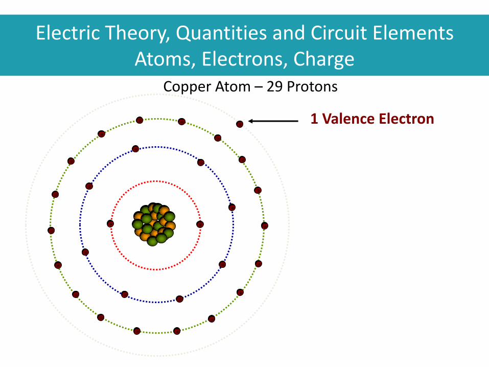
Electric Theory, Quantities and Circuit Elements Atoms, Electrons, Charge
1 Valence Electron
Copper Atom – 29 Protons

Electric Theory, Quantities and Circuit Elements Atoms, Electrons, Charge
• Free Electrons - jump easily from one atom to another
• The number of shells, and electrons in each shell, determine how tightly they are bound to the atom
• In a good conductor the valence electrons can be easily forced to move from one atom to the next

An external force can cause the free electrons to move from
one atom to the next.
friction (static), thermal (thermocouple), light (photocell),
chemical (battery) or electromagnetic (generator)
Force
Electric Theory, Quantities and Circuit Elements Atoms, Electrons, Charge
Conductors and Insulators
W E S T E R N E L E C T R I C I T Y C O O R D I N A T I N G C O U N C I L
17

When it comes to electricity there are generally two types of material:
–Conductors
–Insulators
Electric Theory, Quantities and Circuit Elements Conductors and Insulators

Electric Theory, Quantities and Circuit Elements Conductors and Insulators

Electric Theory, Quantities and Circuit Elements Conductors and Insulators
A conductor is a material that has a large number of free electrons that continually jump to other atoms.
• Good electrical conductors are copper and aluminum. Gold, silver, and platinum are also good conductors, but are very expensive

An insulator is a material that has only a few free electrons. In insulators, the electrons are tightly bound by the nucleus.
• Good electrical insulators are rubber, porcelain, glass, and dry wood
Electric Theory, Quantities and Circuit Elements Conductors and Insulators

Electric Theory, Quantities and Circuit Elements Conductors and Insulators
• Insulators prevent current from flowing
• Insulators are used to isolate electrical components and prevent current flow

Electric Theory, Quantities and Circuit Elements Conductors and Insulators
Electric Theory, Quantities and Circuit Elements Conductors and Insulators
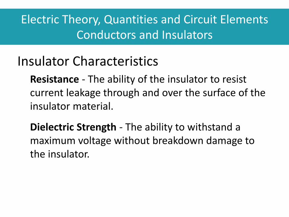
Insulator Characteristics Resistance - The ability of the insulator to resist current leakage through and over the surface of the insulator material.
Dielectric Strength - The ability to withstand a maximum voltage without breakdown damage to the insulator.

Check Your Knowledge: Fundamentals of Electricity
1. In general are objects charged, or neutral? Why is that?
2. Where do you see static electricity?
3. What are good conductors? What are good insulators?
4. What decides which conductor you should use?
25
W E S T E R N E L E C T R I C I T Y C O O R D I N A T I N G C O U N C I L

Current

Current Electric Theory, Quantities and Circuit Elements Current
Current (I) is the movement of charge through a conductor. Electrons carry the charge.
• Unit of measurement: Amperes (A)
• One ampere (amp) of current is one coulomb of charge passing a point on a conductor in one second
• This measurement is analogous to “gallons or liters per second” when measuring the flow of water

Electric Theory, Quantities and Circuit Elements Current
Direct Current (DC) flows in only one direction.
• Many uses including: Batteries, electronic circuits, LED lights, generator excitation systems and rotors, DC transmission lines – and much more

Electric Theory, Quantities and Circuit Elements Current
Alternating Current (AC) continuously changes in magnitude and direction.
• AC is used by most lights, appliances and motors. It is used in the high voltage transmission system
• AC enables use of transformers to change voltage from high to low and back

Electric Theory, Quantities and Circuit Elements Current
Typical Current Levels: Cell phone battery charger 5/1000 Amps = 5mA = (5 milli-amps)
Sensation .2 - .5mA
Let-go threshold 5mA
Potentially lethal 50mA
40 watt incandescent light bulb .33 Amps
Toaster 10 Amps
Car Starter Motor 100+ Amps
Transmission line conductor 1000 Amps
Lightning Bolt or Ground Fault 20,000+ Amps

Voltage

Electric Theory, Quantities and Circuit Elements Voltage
Voltage (V) is the force that causes electrons to move.
• Voltage is also referred to as potential difference or electromotive force (emf or E)
• Unit of measurement: Volts (V)
• Similar to “pounds per square
inch” when measuring water
pressure.
Alessandro Volta (1745–1827)

Electric Theory, Quantities and Circuit Elements Voltage Sources

Electric Theory, Quantities and Circuit Elements Voltage
Sample Voltage Levels
AA Battery 1.5v
Car Battery 12v
Household 120v
Distribution Feeder Circuit 12.47kV
High Voltage Line 47kV to 500kV
Lightning 1,000,000+ volts

Electric Theory, Quantities and Circuit Elements Power

Electric Theory, Quantities and Circuit Elements Power
Power (P) is the rate at which work is being performed.
• Unit of Measurement: watts (w)
• Power = Voltage x Current
• This means that the electrical
energy is being converted into
another form of energy
(e.g. heat energy, light energy,
mechanical energy, etc.) James Watt, 1736 -1819

Electric Theory, Quantities and Circuit Elements Power
W E S T E R N E L E C T R I C I T Y C O O R D I N A T I N G C O U N C I L

Electric Theory, Quantities and Circuit Elements Power
Sample Power Calculation
A Toaster uses 120-volts and allows 10 amps of current to flow. How much power does it consume?
Instructions: Using the formula for power and substituting the known values, we have:
𝑃 = 𝑉𝐼 𝑃 = (_____)(_____) 𝑃 = _____________
38
W E S T E R N E L E C T R I C I T Y C O O R D I N A T I N G C O U N C I L

Electric Theory, Quantities and Circuit Elements Power
Sample Power Calculation
A Toaster uses 120-volts and allows 10 amps of current to flow. How much power does it consume?
Instructions: Using the formula for power and substituting the known values, we have:
𝑃 = 𝑉𝐼 𝑃 = 120𝑉 10𝐴 𝑃 = 1200 𝑊𝑎𝑡𝑡𝑠
39
W E S T E R N E L E C T R I C I T Y C O O R D I N A T I N G C O U N C I L

Electric Theory, Quantities and Circuit Elements Power
• A “watt” is an instantaneous value, it is the power being used at any given instant of time
• A “watt hour” indicates how much power is being consumed over an hour
watt x time (in hours) = watt hours = energy

Electric Theory, Quantities and Circuit Elements Power
Retail Power consumption is typically measured in kilowatt hours (KWh)
Kilowatts x time (in hours) = Kilowatt hours
Example:
5,000 watts used for 3 hours
5,000 = 5 kW
5 kW x 3 hours = 15 kWh
Wholesale power consumption is typically measured in megawatt hours (MWh)
41
W E S T E R N E L E C T R I C I T Y C O O R D I N A T I N G C O U N C I L

Electric Theory, Quantities and Circuit Elements Power
Example Power Use:
• Small light bulb 40 watts
• Toaster 1000 watts or 1 kW
• Household 5–10kW
• One horsepower 746 watts (.746 kW)
• Wind turbine 1,000 kW or 1.0 MW
• Power Plant 500 MW

Electric Theory, Quantities and Circuit Elements Power
Example Power Use:
Small light bulb 40 watts
Toaster 1000 watts or 1 kilowatt (1kW)
Household 5 – 10kW
One horsepower 746 watts (.746 kW)
Wind turbine 1,000 kW or 1.0 Megawatts (MW)
Combined Cycle Power Plant 500 MW

Check Your Knowledge: Fundamentals of Electricity
1. How many volts does a hair dryer use?
2. How many amps?
3. How many watts?
4. How many watts are consumed in a city at 7:00am where 50,000 people are simultaneously drying their hair to get ready for work?
44
W E S T E R N E L E C T R I C I T Y C O O R D I N A T I N G C O U N C I L

Magnetism and Electromagnetism

Electric Theory, Quantities and Circuit Elements Magnetism and Electromagnetism
Wherever an electric current exists, a magnetic field also exists.
• The magnetic field carries the invisible force of magnetism
• The magnetic field surrounds the conductor

CURRENT FLOW
Electric Theory, Quantities and Circuit Elements Magnetism and Electromagnetism
Whenever current flows through a conductor, a magnetic field is created around the conductor.

W E S T E R N E L E C T R I C I T Y C O O R D I N A T I N G C O U N C I L
What happens when you drop a magnet in a copper tube?

Electric Theory, Quantities and Circuit Elements Magnetism and Electromagnetism
Right hand rule for Magnetic Field around a conductor.
Assumes Current flows from Positive to Negative

Electric Theory, Quantities and Circuit Elements Magnetism and Electromagnetism
Magnetic Field Lines of Force

Electric Theory, Quantities and Circuit Elements Magnetism and Electromagnetism

Electric Theory, Quantities and Circuit Elements Electromagnet
52
W E S T E R N E L E C T R I C I T Y C O O R D I N A T I N G C O U N C I L
Current Flow
Battery
+

Electric Theory, Quantities and Circuit Elements Electromagnetic Induction
In order to induce current and voltage you need 3-things:
1. Conductor
2. Magnetic field
3. Relative motion between the conductor and the magnetic field.

W E S T E R N E L E C T R I C I T Y C O O R D I N A T I N G C O U N C I L
Creation of Voltage

Electric Theory, Quantities and Circuit Elements Magnetism and Electromagnetism

N S
Flux Opposite Directions (cancels)
Flux the Same Direction (adds)
Direction of Deflection
Direction
of Deflection
Magnet
Current Carrying
Conductors
Electric Theory, Quantities and Circuit Elements Magnetism and Electromagnetism

Electric Theory, Quantities and Circuit Elements Magnetism and Electromagnetism
• Electromagnetic Induction creates a voltage or current in a conductor when a magnetic field changes
• In a transformer, alternating current in one winding induces a changing magnetic field in the transformer core
• The changing magnetic field induces an alternating voltage and current in the second winding

Electric Theory, Quantities and Circuit Elements Magnetism and Electromagnetism
Basic Transformer Operation
𝑉𝑃𝑟𝑖𝑚𝑎𝑟𝑦= 𝑊𝑖𝑛𝑑𝑖𝑛𝑔𝑠
𝑃𝑟𝑖𝑚𝑎𝑟𝑦
𝑊𝑖𝑛𝑑𝑖𝑛𝑔𝑠 𝑆𝑒𝑐𝑜𝑛𝑑𝑎𝑟𝑦
𝑉𝑆𝑒𝑐𝑜𝑛𝑑𝑎𝑟𝑦

Electric Theory, Quantities and Circuit Elements Magnetism and Electromagnetism
Generator - magnetic field of the rotor Induces a voltage in the stator windings.
• Rotor may be a permanent magnet
• In a large generator, the rotor is a spinning electromagnet – created by current from the exciter
Guide Page #
W E S T E R N E L E C T R I C I T Y C O O R D I N A T I N G C O U N C I L

Whenever a magnetic field is moved past a conductor a voltage is induced in the conductor
Voltmeter N
S
Motion
+
Magnetic Lines of Flux
Electric Theory, Quantities and Circuit Elements Electromagnetic Induction

Circuit Components and Properties
Electric Theory, Quantities and Circuit Elements Circuit Components and Properties
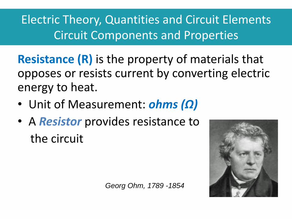
Resistance (R) is the property of materials that opposes or resists current by converting electric energy to heat.
• Unit of Measurement: ohms (Ω)
• A Resistor provides resistance to
the circuit
Georg Ohm, 1789 -1854

Electric Theory, Quantities and Circuit Elements Circuit Components and Properties
Resistance depends on: Resistivity
Conducting material has very low resistivity, insulators have very high resistivity.
Length Decreasing the material's length decreases the resistance.
Cross-sectional area Increasing the material's cross-sectional area decreases the resistance.
Temperature The hotter the wire, the more resistance it exhibits.

Inductance (L) is the property of an electrical circuit that opposes change in current. The unit of inductance is the Henry (H).
• Any component that we use for its inductive property is called an inductor
• In the Power system, an inductor is sometimes also called a reactor
Electric Theory, Quantities and Circuit Elements Circuit Components and Properties

Electric Theory, Quantities and Circuit Elements Circuit Components and Properties
• An Inductor (L) is a coil of wire that creates a magnetic field when current is applied
• The changing magnetic field of an Inductor opposes the voltage that is trying to force current in the wire
• An inductor opposes a change in current
𝑉 = 𝐿𝑑𝐼
𝑑𝑡
(Voltage equals Inductor size times rate-of-change of Current)

Electric Theory, Quantities and Circuit Elements Circuit Components and Properties
Capacitance (C) is the property of an electrical circuit that opposes change in voltage.
• Unit of Measurement: Farads(F)
A Capacitor stores electrical charge.
• A Capacitor consists of two metal plates separated by an insulating layer.
𝑉 = 1/(2𝜋𝑓𝐶) 𝐼𝑑𝑡
(Voltage builds up as current flows into the Capacitor)

Electric Theory, Quantities and Circuit Elements Circuit Components and Properties
• The value of capacitance in a circuit is measured in capacitive units called farads.
• The farad is named after Michael Faraday, a 19th century British physicist, who is credited with developing the method of measuring capacitance.
• Farad determined that a capacitor has a value of one farad of capacitance if one volt of potential difference applied across its plates moved one coulomb of electrons from one plate to the other.
Michael Faraday

Electric Theory, Quantities and Circuit Elements Circuit Components and Properties
• A Capacitor consists of two conducting metal plates with an insulating sheet of material in between.
• When current is applied across the terminals, charge flows from one side to the other.
• Over time as charge builds on the capacitor, voltage increases.

Electric Theory, Quantities and Circuit Elements Circuit Components and Properties: Capacitor Construction
Conducting Plates(electrodes)
Insulating Dielectric

Electric Theory, Quantities and Circuit Elements Circuit Components and Properties
Capacitors come in all sizes and shapes…


Electric Theory, Quantities and Circuit Elements Circuit Components and Properties
Chemical Battery Operation
In the battery, two different metals, called ELECTRODES are placed in a chemical solution called the ELECTROLYTE.
• The metals react differently.
• One loses electrons and develops a positive charge, the other attracts electrons and develops a negative charge.

Electric Theory, Quantities and Circuit Elements Circuit Components and Properties
Chemical Battery Operation
This results in a DIFFERENCE IN POTENTIAL (Voltage) between the two electrodes.
When a conductor is attached to the electrodes of the battery, electrons flow from the negative electrode to the positive electrode.
V

Electric Theory, Quantities and Circuit Elements Circuit Components and Properties
Chemical Battery Operation

Circuit Analysis

Electric Theory, Quantities and Circuit Elements Circuit Analysis - Series and Parallel Circuits

Electric Theory, Quantities and Circuit Elements Circuit Analysis: Series and Parallel Circuits
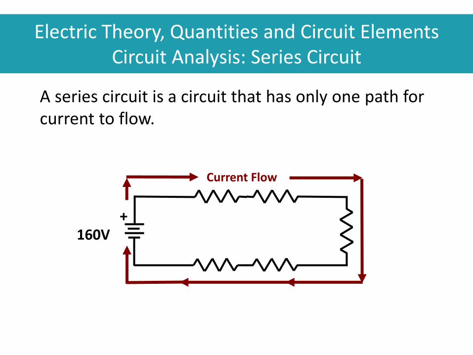
A series circuit is a circuit that has only one path for current to flow.
Current Flow
160V +
Electric Theory, Quantities and Circuit Elements Circuit Analysis: Series Circuit

Total resistance of the circuit (RT)?
RT =
R1 R2 R3
R4 R5 160V
+
5 + 10 + 40 + 20 + 5
R1 + R2 + R3 + R4 + R5 RT =
RT = 80
5 10
40
20 5
Electric Theory, Quantities and Circuit Elements Circuit Analysis: Series Circuit

A parallel circuit is a circuit that has more than one path for current to flow.
120V 50 100 300
CURRENT FLOW
2.4
A
1.2
A
0.4
A 4.0A 1.6A 0.4A
Electric Theory, Quantities and Circuit Elements Circuit Analysis: Parallel Circuit

R1 R2 R3 120V 50 100 300
1
RT
= + 1
R3
+ 1
R2
1
R1
1
RT
= + 1
300
+ 1
100
1
50
1
RT
= 0.02 0.0033 0.01 + +
1
0.0333 = RT 0.0333
1
RT
=
= RT 30
Electric Theory, Quantities and Circuit Elements Circuit Analysis: Parallel Circuit

Ohm’s Law and Kirchoff’s Law
W E S T E R N E L E C T R I C I T Y C O O R D I N A T I N G C O U N C I L
83

Electric Theory, Quantities and Circuit Elements Ohm’s Law
Ohm's Law:
– Voltage Drop = Current * Resistance
Kirchhoff's Laws:
– Sum of current entering a junction equals the sum of current leaving the junction.
– Sum of voltage drops equals the applied voltage.
84
W E S T E R N E L E C T R I C I T Y C O O R D I N A T I N G C O U N C I L

Electric Theory, Quantities and Circuit Elements Ohm’s Law
Ohm’s law, named after Mr. Georg Ohm, a German mathematician and physicist. 1789 -1854.
He defined the basic relationship between power, voltage, current and resistance.
The principles apply to AC, DC or RF (radio frequency).

Electric Theory, Quantities and Circuit Elements Ohm’s Law
V = IR
I = V/R
R = V/I
Where:
V = Voltage in Volts
I = Current in Amps
R = Resistance in Ohms
86
W E S T E R N E L E C T R I C I T Y C O O R D I N A T I N G C O U N C I L

E
I R
Electric Theory, Quantities and Circuit Elements Ohm’s Law: Pie or Triangle

Electric Theory, Quantities and Circuit Elements Quick question
How much current is flowing in the toaster circuit?
I = __ amps

Electric Theory, Quantities and Circuit Elements Quick question
How much current is flowing in the toaster circuit?
I = 10 amps

Kirchhoff's Current Law: the sum of the currents entering a junction equals the sum of the currents leaving a junction.
• For series circuits - the current is the same at all points
• For parallel circuits - the total current in a parallel circuit is equal to the sum of the currents in each branch
Electric Theory, Quantities and Circuit Elements Kirchoff’s Law

Gustav Kirchoff was a German
Physicist 1824 – 1887.
He developed laws for circuit
analysis as well as other laws for
“black body” radiation and
thermochemistry.
Electric Theory, Quantities and Circuit Elements Kirchoff’s Law
Kirchhoff’s Voltage Law states:
• The voltage difference across a resistor is called a voltage drop
• In series circuits, the sum of the voltage drops around the circuit is equal to the applied voltage
• In parallel circuits, the voltage drops across all the branches are the same
Electric Theory, Quantities and Circuit Elements Kirchoff’s Law

Check Your Knowledge: Fundamentals of Electricity
1. A blow drier uses 120 Volts and draws 10 amps. What is its resistance?
2. How much power does it use? 3. How much would it cost to run the blow drier for one hour? 4. If you had two similar blow dryers plugged in to the wall –
would they be in series or parallel? 5. How many amps total would they use? 6. If you re-wired the blow dryers to put one in series with the
other, what would be the total resistance? 7. How much current would flow through the circuit? 8. What would the voltage across each dryer be? 9. What would be the total power used?
93
W E S T E R N E L E C T R I C I T Y C O O R D I N A T I N G C O U N C I L

Alternating Current
• Generating AC Current
• Sine Waves
• RMS Values
• Phase Relationship
• Right Triangle Relationships
• Impedance–Resistance, Inductance, Capacitance

Alternating Current (AC)
Alternating Current (AC) periodically changes direction of flow and magnitude.
• AC voltage produces an alternating current
• AC power is produced by alternating current and alternating voltage

Generating AC Current
W E S T E R N E L E C T R I C I T Y C O O R D I N A T I N G C O U N C I L
96

N S
0° 90° 180° 270° 360° Time
Rotation 0°
90°
270° +
_
180°
Amplitude
of Voltage
or Current
0V
Generator

N
S
0° 90° 180° 270° 360° Time
+
_
Current Flow
_
+
Amplitude
of Voltage
or Current
90°
270°
0° 180°
Generator

N
S
0° 90° 180° 270° 360° Time
+
_
Current Flow
_
+
Amplitude
of Voltage
or Current
90°
270°
0° 180°
Generator

N
S
0° 90° 180° 270° 360° Time
+
_
Current Flow
_
+
Amplitude
of Voltage
or Current
90°
270°
0° 180°
Generator

N S
0° 90° 180° 270° 360°
Amplitude
of Voltage
or Current
Time
+
_ 0V
90°
270°
0° 180°
Generator

N
S
0° 90° 180° 270° 360° Time
+
_
Current Flow
+
_
Amplitude
of Voltage
or Current
90°
270°
0° 180°
Generator

N
S
0° 90° 180° 270° 360° Time
+
_
Current Flow
+
_
Amplitude
of Voltage
or Current
90°
270°
0° 180°
Generator

0° 90° 180° 270° 360° Time
+
_
Current Flow
+
_
N
S
Amplitude
of Voltage
or Current
90°
270°
0° 180°
Generator

0° 90° 180° 270° 360° Time
0° (360°)
+
_
N S
Amplitude
of Voltage
or Current
0V
90°
270°
180°
Generator

Sine Waves
W E S T E R N E L E C T R I C I T Y C O O R D I N A T I N G C O U N C I L
106

A Sine Wave is a curve that describes a smooth repetitive oscillation.
Alternating Current (AC) Sine Waves

A Sine Wave shows the height of the circle at a given angle.
𝐴1 0º
90º
180º
270º
0º
90º
180º
270º
𝐴2
𝐴3 𝐴1 𝐴2 𝐴3
Alternating Current (AC) Sine Waves

𝐴1 0º
90º
180º
270º
0º
90º
180º
270º
𝐴1
Spinning Generator Rotor Sine Wave Voltage
Rotor
Rotor Angle = Phase Angle
Spinning Generator Rotor creates a Sine Wave Voltage
Alternating Current (AC) Sine Waves

A Cycle is the part of a waveform that does not repeat or duplicate itself. In the time it takes to complete one cycle, the current:
builds from zero to the maximum amplitude in one direction
decays back to zero
builds to the maximum amplitude in the opposite direction
decays back to zero again
Alternating Current (AC) Sine Waves

• The Period (T) is the time required to complete one cycle
• Frequency (f) is the rate at which the cycles are produced
• Frequency is measured in Hertz (Hz). One hertz equals one cycle per second
Alternating Current (AC) Sine Waves

Frequency (f) and period (T) are related by the following equations:
f = 1/T T = 1/f
Alternating Current (AC) Sine Waves
Amplitude
– peak
– peak-to-peak
– RMS (Effective Value)
Alternating Current (AC) Sine Waves

Maximum Negative Value
Peak-to-Peak
Maximum Positive Value
Peak
Alternating Current (AC) AC Power Sine Wave

RMS Values
W E S T E R N E L E C T R I C I T Y C O O R D I N A T I N G C O U N C I L
115

Alternating Current (AC) RMS (Effective) Value
• The effective or root mean square (RMS) is the amount of AC current or voltage that has the same effect as a given amount of DC current or voltage in producing heat in a resistive circuit
• Effective value (RMS) is the most common way of specifying the amount of AC
• One amp of effective AC and one amp of DC produce the same power when flowing through equal resistors

• The Root Mean Square (RMS) Value is the Effective value
• To calculate the RMS value of a waveform, Square the instantaneous values over one period, average them to provide the Mean, and take the square Root of the mean
• RMS value is 70.7% of Peak value
𝐼𝑟𝑚𝑠 =2
2𝐼𝑝 = .707 𝐼𝑝
Alternating Current (AC) RMS Values

RMS Value
70.7% of Peak Voltage
Zero
Alternating Current RMS (Effective) Value

VP-P = 340 V
Vpeak = 170 V
Vpeak = 170 V
VRMS = .707 x 170 V = 120.2 V
Vrms = 120 V
Alternating Current Household Voltage

60
50
40
30
20
10
0
-10
-20
Average Power 25 Watts
10 Volts, 7.07V rms
5 Amps, 3.53A rms
RMS Voltage * RMS Current = Average Power
0 30 60 90 120 150 180 210 240 270 300 330 360
50 Watts Peak Power

Phase Relationship
W E S T E R N E L E C T R I C I T Y C O O R D I N A T I N G C O U N C I L
121

Alternating Current (AC) Phase Relations
Phase Angle is the angle difference between two sine waves with the same frequency
• Phase Angle is sometimes called phase relation
• Phase angle is the portion of a cycle that has elapsed since another wave passed through a given value

Alternating Current (AC) Phase Angle Between Two Generators
𝐴1 0º
90º
180º
270º
𝐴1
Two Generators - Out of Phase Sine Wave Voltages
Gen 1
Relative Rotor Angle = Phase Angle
Gen 2
Gen 1
Gen 2

𝐴1 0º
90º
180º
270º
𝐴1
Two Generators – Out of Phase Sine Wave Voltages
Gen 1
Relative Rotor Angle = Phase Angle
Gen 2
Gen 1
Gen 2
Alternating Current (AC) Phase Angle Between Two Generators
Angle between Generators stays the same while they both rotate

Figure 2.8: Phase Angle
V1 = Generator #1 V2 = Generator #2
Alternating Current (AC) Phase Relations
Alternating Current (AC) Phase Angle Between Two Generators
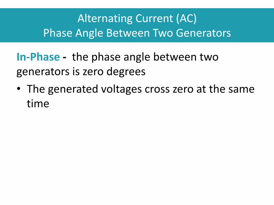
In-Phase - the phase angle between two generators is zero degrees
• The generated voltages cross zero at the same time

Alternating Current (AC) Phase Angle Between Two Generators
Out-of-Phase means that the phase angle between two generators is not zero degrees.
• The generated voltages cross zero at different times
• Only applies if the two waveforms have the same frequency

A phasor is a line representing a rotating quantity (voltage or current) for which:
Length represents magnitude
Direction represents the phase angle (in electrical degrees)
Zero electrical degrees are on the right side of the horizontal axis
Rotation is counterclockwise
Alternating Current (AC) Phase Relations

A phasor is similar to an arrow drawn on the end of a spinning shaft
• A strobe light flashes once each time the shaft does a full revolution
Alternating Current (AC) Phase Relations

𝐴1 0º
90º
180º
270º
0º
90º
180º
270º
𝐴1
Spinning Generator Rotor Sine Wave Voltage
Phasor
Rotor Angle = Phase Angle
Alternating Current (AC) Phase Relations

Since phasors rotate in a counterclockwise direction, the phasor diagram above shows the current leading the voltage by 30º.
30°
90º
180º
270º
Phasors – Voltage and Current
Voltage Phasor
Current Phasor
Alternating Current (AC) Phase Relations

Right Triangle Relationships
W E S T E R N E L E C T R I C I T Y C O O R D I N A T I N G C O U N C I L
132

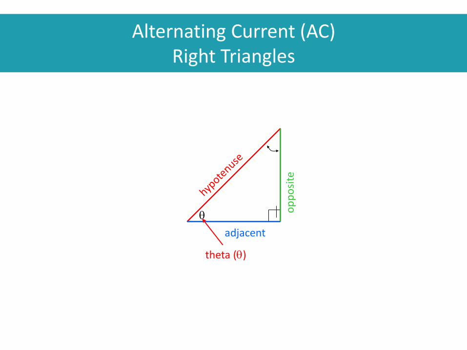
Alternating Current (AC) Right Triangles
A Right Triangle has one corner with a 90º Angle.
q
adjacent
op
po
site
Symbol for a right angle (900)

Alternating Current (AC) Right Triangles
The right triangle can be used to represent:
– Resistance vs Reactance
– Real versus Reactive portion of Current and Voltage
– Real and Reactive Power

The right triangle can be used to represent the resistive, reactive, and Resulting total.
Alternating Current (AC) Right Triangles
Real
Reactive

Alternating Current (AC) Right Triangles
Angles total 180º 450
450
900
1800
600
300
900
1800
Alternating Current (AC) Right Triangles
q
adjacent
op
po
site
theta (q)

Right Triangles
The Pythagorean Theorem states that the square of the hypotenuse of a right triangle is equal to the sum of the squares of the remaining two sides.
q
adjacent
op
po
site
Pythagorean Theorem

Right Triangles
The Pythagorean Theorem states that the square of the hypotenuse of a right triangle is equal to the sum of the squares of the remaining two sides.
q
adjacent
op
po
site
9
16
25
hypotenuse2 = + opposite2 adjacent2

Alternating Current (AC) Right Triangles
140
Pythagorean Theorem

Alternating Current (AC) Right Triangles
Using our formula, we could find the value of any side if we know the value of the other two sides.
q
A
B
Pythagorean Theorem
C2 = A2 + B2
C2 = A2 + B2
or
A2 = C2 - B2
or
B2 = C2 - A2

Alternating Current (AC) Right Triangles
Generators produce Mega-Watts and Mega-Vars. Use the right triangle to find the values.
q
MW
MV
AR
Pythagorean Theorem
MVA2 = MW2 + MVAR2
MVA2 = MW2 + MVAR2
MVA2 = - MVAR2
MVA2 = MW2 -
MW2
MVAR2

Alternating Current (AC) Right Triangles
If a generator was producing 100 MW and 50 MVAR we could calculate the MVA using our formula.
q
100 MW
50
MV
AR
MVA2 = 1002 + 502
MVA2 = 10,000 + 2,500
MVA2 = 12,500
MVA = 111.8
Pythagorean Theorem

q
adjacent
op
po
site
Sine and Cosine
Sine q =
opposite
hypotenuse
Cosine q =
adjacent
hypotenuse
Alternating Current (AC) Right Triangles

This ratio of Adjacent side to Hypotenuse establishes the slope of the angle
q
4
Sine and Cosine
5
4 cosine q =
Alternating Current (AC) Right Triangles

Determine the angle theta using the inverse of the cosine of theta the arccosine.
q
4
Sine and Cosine
cosine q = 5
4
cosine q = 0.8
arccosine 0.8 = 36.860 36.90
q = 36.90
Alternating Current (AC) Right Triangles

q
4
Sine and Cosine
36.90
900
1800
900
36.90
53.10
-
Alternating Current (AC) Right Triangles

We can solve for all angles and sides given only one side and one angle
q 36.90
Alternating Current (AC) Right Triangles

Alternating Current (AC) Right Triangles
q 36.90
arccosine q = 36.90
cosine q (36.9) = 0.8
a = 0.8 X 5
a = 4
a
o

Alternating Current (AC) Right Triangles
q 36.90
a = 4
o2 = h2 - a2
o2 = 25 - 16
o2 = 9
o = 3
o
O = 5 sin(36.9) = 3 OR

Alternating Current (AC) Right Triangles
Summary
• A right triangle has one right angle (90º)
• The sum of the angles of any triangle equals 1800
• The sides of a right triangle are named the hypotenuse, adjacent and opposite side.
• The hypotenuse of any right triangle will always be the longest side.
• The square of the hypotenuse is equal to the sum of the squares of the remaining two sides
• The sine equals the ratio of the opposite side to the hypotenuse
• The cosine equals the ratio of the adjacent side to the hypotenuse

Alternating Current (AC) Right Triangles
Practice Question
q 41.40
Solve the unknown sides and angles of this right triangle using the methods we have learned in this module on right triangles.

Resistive, Reactive, and Total Impedance
Alternating Current (AC) Right Triangles
Resistance R
Reactance X
Application to Electricity

Total Voltage drop equals the voltage drop across resistor squared plus voltage drop across reactor squared.
Alternating Current (AC) Right Triangles
I*R = VR
I*X = VX
Application to Electricity

Apparent Power = Real Power + Reactive Power (Vars)
Alternating Current (AC) Right Triangles
Application to Electricity
I*VR=Real Power =MWatts
I*VX=Reactive Power = MVars

Check Your Knowledge: Fundamentals of Electricity
1. In a right triangle with the adjacent side equal to 5 and
the opposite side equal to 12, what is the length of the
hypotenuse?
2. Can you prove graphically that the Pythagorean
Theorem is true?
3. What is the sine of 45 degrees?
4. With a hypotenuse of one and an adjacent side of .5,
what is the angle? The opposite side?
156
W E S T E R N E L E C T R I C I T Y C O O R D I N A T I N G C O U N C I L

Impedance Resistance, Inductance, Capacitance
W E S T E R N E L E C T R I C I T Y C O O R D I N A T I N G C O U N C I L
157

Alternating Current (AC) Impedance
Impedance (Z) is the total opposition to current.
• Impedance is the vector sum of the resistance and reactance
• Impedance is represented by a Z and measured in ohms (Ω)
Real R
Reactive X

Alternating Current (AC) Impedance
• Impedance of resistors is independent of whether the current is AC or DC
• Impedance of inductors and capacitors depends on the rate-of-change or frequency of the voltage
Alternating Current (AC) Impedance
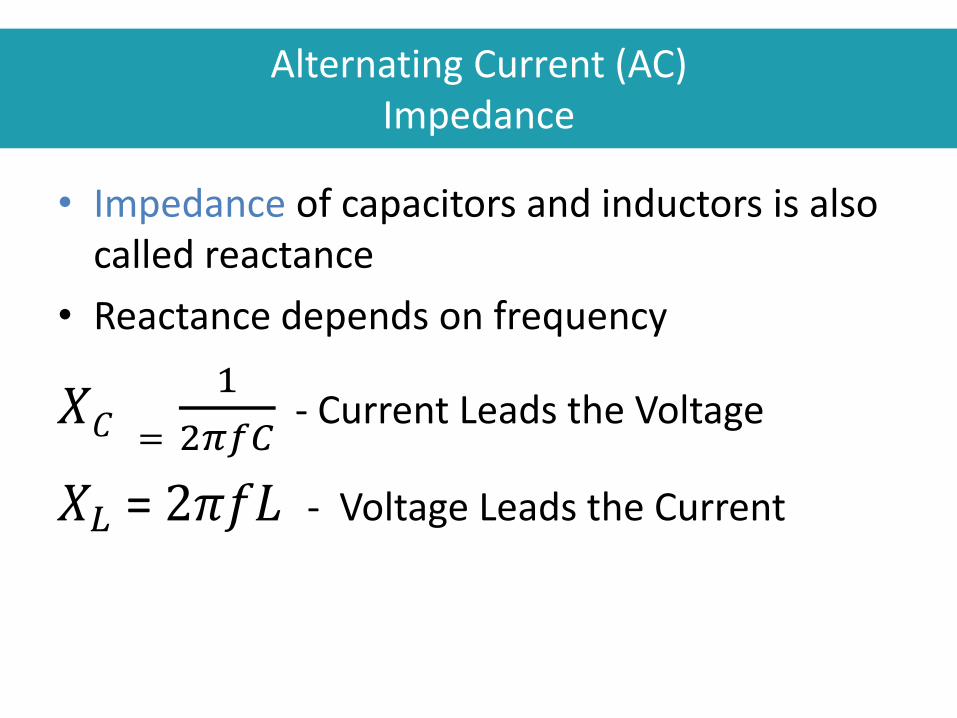
• Impedance of capacitors and inductors is also called reactance
• Reactance depends on frequency
𝑋𝐶 =
1
2𝜋𝑓𝐶 - Current Leads the Voltage
𝑋𝐿 = 2𝜋𝑓𝐿 - Voltage Leads the Current

Alternating Current (AC) Impedance
Inductive Reactance(XL) opposes change in current. It is measured in ohms(Ω).
• Reactance does not convert the electrical energy into heat energy
• The reactor temporarily stores the energy in the expanding magnetic field, then gives it back when the field collapses

Alternating Current (AC) Impedance
Applied EMF
Counter EMF
I
XL
Inductors are devices that oppose changes in current flow using a magnetic field.

Alternating Current (AC) Impedance
This form of Ohm's Law applies to inductive reactance:
𝑉 = 𝐼𝑋𝐿
Where: • V and I = Voltage and current, respectively
• 𝑋𝐿 = 2𝜋𝑓𝐿= Inductive Reactance
• 𝜋 = Constant (approximately 3.14)
• f = Frequency
• L = Inductance
The Current lags the voltage by 90º
V
I XL

Inductance
The current lags the voltage by 90º in this example.

Applied Voltage
Current Lags Voltage by a Maximum 90°
Circuit Current
The maximum amount that the inductance can cause the current to lag behind the voltage is 90°
Alternating Current (AC) Inductance
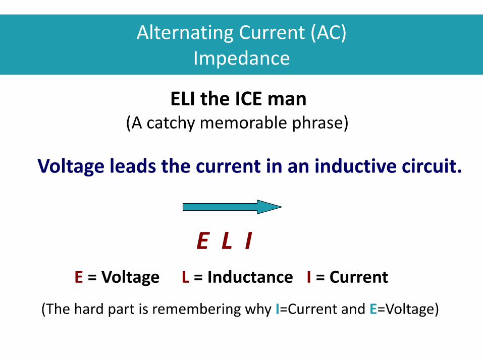
E L I
E = Voltage L = Inductance I = Current
Voltage leads the current in an inductive circuit.
ELI the ICE man (A catchy memorable phrase)
(The hard part is remembering why I=Current and E=Voltage)
Alternating Current (AC) Impedance

Inductive loads


Alternating Current (AC) Impedance
Capacitive Reactance (Xc) opposes change in voltage. It is measured in ohms(Ω).
• Reactance does not convert the electrical energy into heat energy
• The capacitor temporarily stores the energy in the electric field between its plates, then gives it back when the field collapses

Alternating Current (AC) Impedance
Capacitors are devices that store electrical charge. They oppose a change of voltage.
+ +
Voltage

The following form of Ohm's Law applies to capacitive reactance:
𝑉 = 𝐼𝑋𝐶
Where:
• V and I = Voltage and current, respectively. • 𝑋𝐶 = 1/(2𝜋𝑓𝐶)= Capacitive Reactance
• 𝜋 = Constant (approximately 3.14) • f = Frequency • C = Capacitance
Current can lead the voltage by up to 90º.
V
I XC
Alternating Current (AC) Impedance
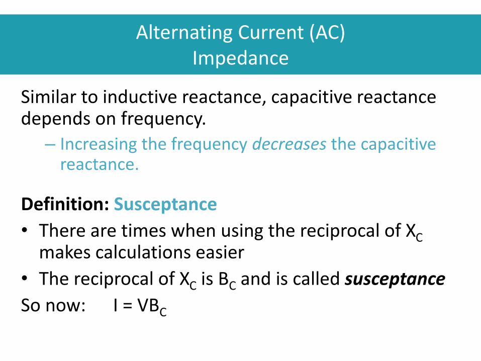
Similar to inductive reactance, capacitive reactance depends on frequency.
– Increasing the frequency decreases the capacitive reactance.
Definition: Susceptance
• There are times when using the reciprocal of XC makes calculations easier
• The reciprocal of XC is BC and is called susceptance
So now: I = VBC
Alternating Current (AC) Impedance

E L I
I = Current C = Capacitance E = Voltage
Current leads the voltage in a capacitive circuit.
ELI the ICE man (A catchy memorable phrase)
(The hard part is remembering why I=Current and E=Voltage)
Alternating Current (AC) Impedance

Check Your Knowledge: Fundamentals of Electricity
1. With a Voltage of 120 volts, Resistance of
10Ω and Inductive Reactance of 5Ω. What is
the current?
2. Does the current lead or lag the voltage?
3. What is the angle between the current and
the voltage legs of the triangle?
178
W E S T E R N E L E C T R I C I T Y C O O R D I N A T I N G C O U N C I L

Power in AC Circuits
• Resistive Circuits - Watts
• Reactive Circuits – VARS
• Complex Power
• Power Triangle
• Power Factor
• VARs – Effect on Voltage
• Voltage Collapse


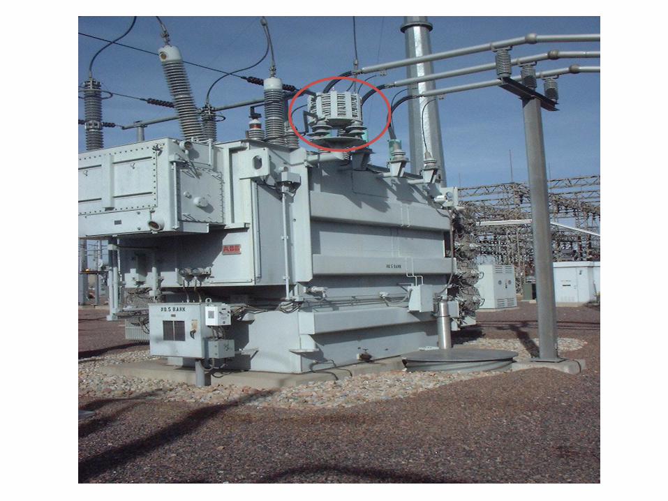
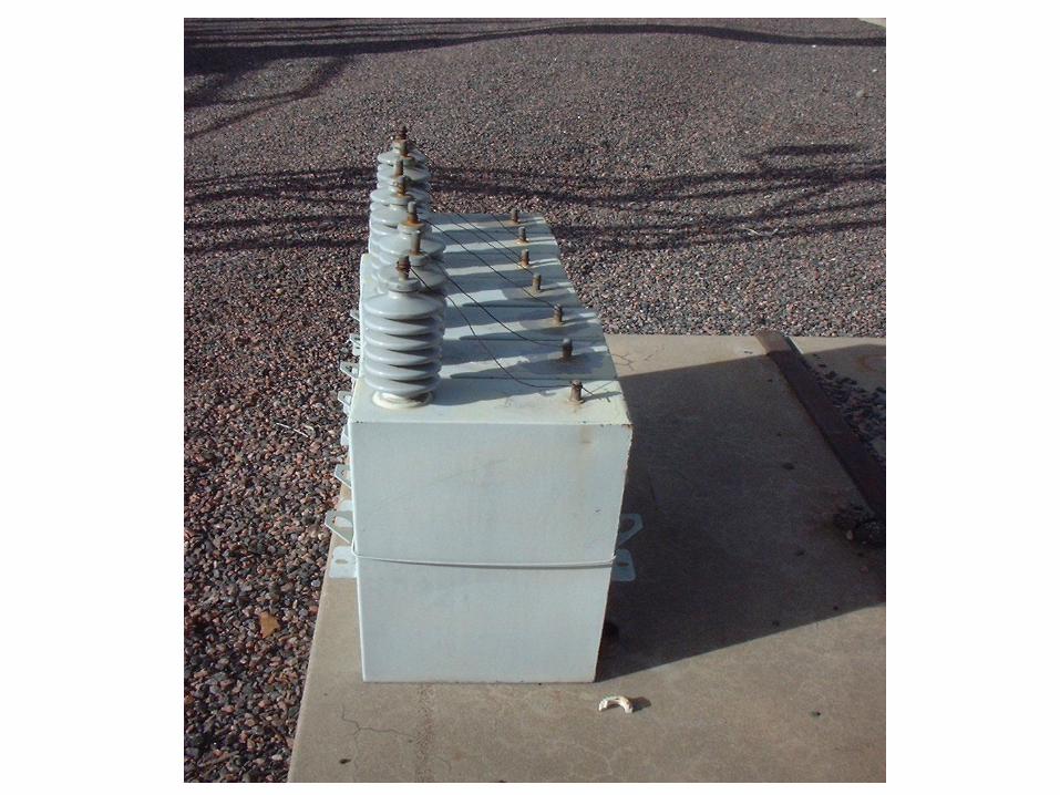
Power Capacitors


Resistive Circuits - Watts
W E S T E R N E L E C T R I C I T Y C O O R D I N A T I N G C O U N C I L
184

Power is the rate at which work is performed it is measured in watts.
• In a resistive circuit, the current and voltage are in phase.
• Real Power is the power consumed by the resistance in a circuit.
Power in AC Circuits Resistive Circuits

60
50
40
30
20
10
0
-10
-20
Average Power 25 Watts
10 Volts, 7.07V rms
5 Amps, 3.53A rms
REAL POWER IN A RESISTIVE CIRCUIT
0 30 60 90 120 150 180 210 240 270 300 330 360
50 Watts
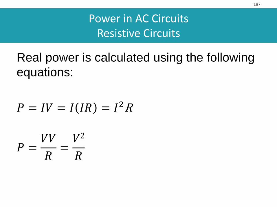
Power in AC Circuits Resistive Circuits
Real power is calculated using the following
equations:
𝑃 = 𝐼𝑉 = 𝐼 𝐼𝑅 = 𝐼2R
𝑃 =𝑉𝑉
𝑅=𝑉2
𝑅
187

• Losses are dissipated as heat in transmission lines and transformers
• I2R = Heating Losses
• Most circuits are not entirely resistive – they contain reactance
Power in AC Circuits Resistive Circuits
Reactive Circuits - VARs
W E S T E R N E L E C T R I C I T Y C O O R D I N A T I N G C O U N C I L
189

Reactance causes a phase shift between voltage and the current.
Power in AC Circuits Reactive Circuits

Power in AC Circuits Reactive Circuits
𝑉 = 𝐼𝑅 + 𝐼𝑋 < 90°
IR
IX V
90°
Note: Reactive Impedance of a Transmission line is much larger then the resistance.

Power in AC Circuits Reactive Circuits
Reactive Power is the power used to support the magnetic and electric fields found in inductive and capacitive loads throughout a power system.
• Reactive power is measured in volt-amps-reactive (Vars)

Complex Power
W E S T E R N E L E C T R I C I T Y C O O R D I N A T I N G C O U N C I L
193

Power in AC Circuits Complex Power
Complex Power = Real Power + Reactive Power.
• Unlike resistors; inductors and capacitors do not consume power, they store and release energy
• In a resistive circuit, the current and voltage are in phase. But that is not the case in a reactive circuit

Power in AC Circuits Complex Power
• Reactive Power supports the magnetic
and electric fields found in inductive and
capacitive loads
• Reactive power is measured in volt-
amperes reactive (Vars)
195

Power in AC Circuits Complex Power
We use phasors and right triangle relationships to break the current and voltage into resistive and reactive parts.
𝐴1 0º
90º
180º
270º
0º
90º
180º
270º
𝐴1
Rotor
Rotor Angle = Phase Angle
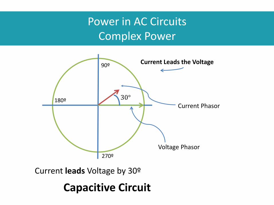
Current leads Voltage by 30º
30°
90º
180º
270º
Current Leads the Voltage
Voltage Phasor
Current Phasor
Power in AC Circuits Complex Power
Capacitive Circuit

Current leads Voltage by 30º
30°
Voltage Phasor
Total Current Phasor
Power in AC Circuits Complex Power
Part of the Current is in-phase with the voltage. Part of the Current is out-of-phase with the voltage.
IX=Out of Phase Current
IR=In Phase Current

Current leads Voltage by 30º
30°
Power in AC Circuits Complex Power
Part of the Current is in-phase with the voltage. Part of the Current is out-of-phase with the voltage.
VIX=Reactive Power = VARS
VIR= Real Power = Watts
Leading!

Current Lags Voltage by 30º
30°
90º
180º
270º
Current Lags the Voltage
Voltage Phasor
Current Phasor
Power in AC Circuits Complex Power
Inductive Circuit

Current Lags Voltage by 30º
30°
Power in AC Circuits Complex Power
VIX=Reactive Power = VARS
VIR= Real Power = Watts
Lagging
Inductive Circuit

Power in AC Circuits Complex Power
• When voltage and current are not in phase or in sync, there are two components: • Real or active power is measured in Watts • Reactive (sometimes referred to as imaginary)
power is measured in VARs • The combination (vector product) is Complex Power
or Apparent Power • The term “Power” normally refers to active power
Power in AC Circuits Complex Power
Real power does the work; it does the heating, lighting, and turning of motors, etc.
It is measured in Watts

Power in AC Circuits Complex Power
Reactive power supports magnetic and electric fields required for AC systems to function.
It is measured in:
Volt-Amperes-Reactive (VARs)

Power Triangle
W E S T E R N E L E C T R I C I T Y C O O R D I N A T I N G C O U N C I L
205

Angle between Apparent Power and Real Power is Ɵ
Ɵ
Power in AC Circuits Power Triangle
VIX=Reactive Power = VARS
VIR= Real Power = Watts

Power Factor
W E S T E R N E L E C T R I C I T Y C O O R D I N A T I N G C O U N C I L
207

Power Factor (PF) is the ratio of real power to apparent power.
Power factor = 𝑊𝑎𝑡𝑡𝑠
𝑉𝐴
Power in AC Circuits Power Factor
Ɵ
VARS
Watts

The Power Factor (cos Ө) = Real/Apparent
Power in AC Circuits Power Factor
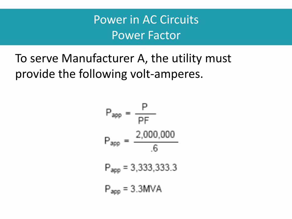
To serve Manufacturer A, the utility must provide the following volt-amperes.
Power in AC Circuits Power Factor

To serve this load, the utility's conductors must be able to carry the following current:
Power in AC Circuits Power Factor
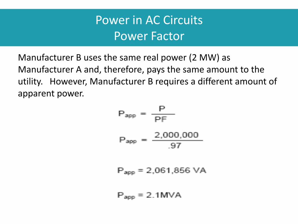
Manufacturer B uses the same real power (2 MW) as Manufacturer A and, therefore, pays the same amount to the utility. However, Manufacturer B requires a different amount of apparent power.
Power in AC Circuits Power Factor

And, the current drawn by Manufacturer B is:
Power in AC Circuits Power Factor

Manufacturer B draws much less current to obtain the same real power. Utilities design their transmission and distribution systems based on the apparent power and the current they must deliver. Since utilities bill their customers for the true power used, utilities encourage the use of high-power factor systems.
Power in AC Circuits Power Factor
VARs – Effect on Voltage
W E S T E R N E L E C T R I C I T Y C O O R D I N A T I N G C O U N C I L
215

Power in AC Circuits VAR Effect on Voltage Control
Reactive power supply is the most important element in controlling voltage.
Why? If I put a lagging reactive current that is 90º out of phase through a reactive line impedance that is 90º out of phase, it results in a 180º voltage drop.
216

Current In Phase with Voltage
90º
180º
270º
Receiving End Voltage Phasor
Current Phasor
Power in AC Circuits VAR effect on Voltage Control
Resistive Load

Current In Phase with Voltage
90º
180º
270º
Voltage Drop due to Line Resistance (Parallel to Current)
Sending End Voltage
Current Phasor
Power in AC Circuits VAR effect on Voltage Control
Resistive Load
Voltage Drop due to Line Reactance (90º to Current)
Receiving End Voltage

Load Current Lags Voltage by 30º
30°
90º
180º
270º
Current Lags the Voltage
Receiving End Voltage Phasor
Current Phasor
Power in AC Circuits VAR effect on Voltage Control
Inductive Load

Current Lags Voltage by 30º
30°
90º
180º
270º
Voltage Drop due to Line Resistance (Parallel to Current)
Receiving End Voltage
Load Current
Power in AC Circuits VAR effect on Voltage Control
Inductive Load
Sending End Voltage
Voltage Drop due to Line Reactance (90º to Current)

30°
90º
180º
270º
Power in AC Circuits VAR effect on Voltage Control
Lagging Load Current
Voltage Drop High VARS
Voltage Drop Low VARS

Power in AC Circuits VAR Effect on Voltage Control
Voltage fluctuates due to:
Load
• Consumes VARs
• More load, more VARs used
Lines – inductive impedance
• More load, more VAR losses
• Loss of a transmission line means other lines load heavier and we experience even more VAR losses

Voltage Collapse
W E S T E R N E L E C T R I C I T Y C O O R D I N A T I N G C O U N C I L
223

Voltage Collapse – when the grid system experiences an uncontrollable reduction in voltage due to a deficiency in reactive power (VARS).
Power in AC Circuits Voltage Collapse
Real Real Real Real
VAR
VAR
VAR No VAR

Power in AC Circuits WHAT are VARs?
System Operator and Engineering Terms
• Volt Amp Reactive
• Reactive Power
• Imaginary Power
• Part of Complex Power
• Part of Apparent Power
225

Power in AC Circuits WHAT are VARs?
VAR analogy --- Building a roof
Flat roof with no vertical load is OK (Voltage is OK)
Flat roof with vertical load (VARS) Sags (Voltage Sags)
Slanted roof with VARS added to compensate for load VARS is ok

Power in AC Circuits WHAT are VARs?
• VARs support the system and pull down or push up the voltage
• When circuits result in the current leading the voltage, voltage rises as VARs increase
• When circuits result in the current lagging the voltage, voltage decreases as VARs are consumed

Power in AC Circuits Why do WE need Reactive Power
“Reactive power (VARs) is required to maintain the voltage to deliver active power (watts) through transmission lines. Motor loads and other loads require reactive power to convert the flow of electrons into useful work. When there is not enough reactive power, the voltage sags down and it is not possible to push the power demanded by loads through the lines.”
(“Signatures of the Blackout of 2003”, Roger C. Dugan et. al.)

Power in AC Circuits Importance of Reactive Power
• Refers to the circulating power in the grid that does no useful work
• Results from energy storage elements in the power grid (mainly inductors and capacitors)
• It must be controlled to prevent voltage problems.
• Reactive power levels have an effect on voltage collapse
• The reactive power flow should be minimized to reduce losses. This ensures that the system operates efficiently

Power in AC Circuits Reactive Power is a Byproduct of AC systems
• Transformers, transmission lines, and motors require reactive power.
• Transformers and transmission lines introduce inductance as well as resistance.
• Both oppose the flow of current
• Must raise the voltage higher to push the power through the inductance of the lines.
• Unless capacitance is introduced to offset inductance
• The farther the transmission of power, the higher the voltage needs to be raised.

Power in AC Circuits Reactive Power & Power Factor
• Reactive power is present when the voltage and current are not in phase
• One waveform leads the other • Phase angle not equal to Zero Degrees • Power factor less than unity
• Measured in volt-ampere reactive (VAR) • Produced when the current waveform leads
voltage waveform (Leading power factor) • Vice versa, consumed when the current
waveform lags voltage (lagging power factor)

AC Voltage & Current Phase Shift due to Inductance
Current Lags Voltage
Per
Un
it
0.00 0.20 0.40 0.60 0.80 1.00
Time
1.00
0.80
0.60
0.40
0.20
0.00
-0.20
-0.40
-0.60
-0.80
-1.00
V=IR+IXL
Voltage
Current
Power
Φ
V
I

Power Triangle
True Power = Watts
Reactive Power = VARS
θ Phase Angle
Volt-Amperes = (VA) = Apparent Power
Watts = (W) = True Power
Vars = (VARS) = Volt-Amperes Reactive
Power Factor = (PF) = Watts/(Volt Amperes)
Phase Angle = Ɵ = COS-1 (PF) = Angular displacement between voltage & current

Power in AC Circuits Power Triangle
234

Power in AC Circuits Reactive Power Limitations
• Reactive power does not travel very far
• Usually necessary to produce it close to the location where it is needed
• A supplier/source close to the location of the need is in a much better position to provide reactive power – versus one that is located far from the location of the need
• Reactive power supplies are closely tied to the ability to deliver real or active power

Check Your Knowledge: Fundamentals of Electricity
1. In a Resistive Load the current A) Leads, B) Lags, C) is in phase with the voltage. T/F?
2. A load consists of a 4 ohms resistor in parallel with a 3 ohm reactor with a voltage of 10 volts.
a. What is the total Impedance?
b. Current?
c. Real Power?
d. Reactive Power?
e. Power Factor?
236
W E S T E R N E L E C T R I C I T Y C O O R D I N A T I N G C O U N C I L

Three-Phase Circuits
• Definition and Advantages
• Three Phase Connections

W E S T E R N E L E C T R I C I T Y C O O R D I N A T I N G C O U N C I L
WYE vs. Delta

Definition and Advantages

Three-Phase Circuits Definition and Advantages
• Almost all electricity is generated and distributed as three-phase rather than single-phase
• Cost of three-phase is less than single-phase
• Uses fewer conductors
• Reduces Losses

Three-Phase Circuits Definition and Advantages
Phase Neutral
3 – Single Phase Lines
=
1 – 3 Phase Line
Phase Phase
Phase Phase Phase Neutral Neutral
Six Conductors Three Conductors
Neutral Current – returns on other two phases

Three-Phase Circuits Definition and Advantages
Phase A
Phase A= - (Phase B +Phase C)
Neutral Current – returns on other two phases

Three-Phase Circuits Definition and Advantages
• More constant load on the generator shaft.
• Single-phase load on the generator shaft goes from zero to maximum power and back to zero with each cycle.
• With three-phase current, at least two of the phases provide current (and therefore, power) at any instant.
• Load on a three-phase generator never reduces to zero. This uniform load allows smoother operation of the generator…

A Phase C Phase B Phase
Three-Phase Circuits Definition and Advantages

In a three-phase circuit:
• An AC voltage generator produces three evenly spaced sinusoidal voltages, identical except for a phase angle difference of 120º
• Three conductors transmit the electric energy. The conductors are called phases and are commonly labeled A Phase, B Phase, and C Phase
• Each phase conductor carries its own phase current
Three-Phase Circuits Definition and Advantages

0o
120o
240o
360o
A Phase C Phase B Phase
Three-Phase Circuits Three-Phase Power

A
B
C
A B C +
Three-Phase Circuits Generating 3-Phase Power Waves

1/60th sec.
+
-
Three-Phase Circuits vs. Single Phase Power

Three-Phase Circuits Three-Phase Power

Three-Phase Circuits Interconnected 3-Phase Power
In an AC interconnection, all connected utilities see the same electrical frequency and all generators operate in synchronism with each other.
W E S T E R N E L E C T R I C I T Y C O O R D I N A T I N G C O U N C I L

• Definition: Phase-to-Phase and Line Voltages
• The voltages between the outputs of the generator are called the line voltages (sometimes called phase-to-phase voltages).
• The line voltages are equal to the phase voltages.
• When a Delta-connected generator is loaded, current flows in the loads, lines, and phase windings.
Three-Phase Circuits Definition and Advantages

Three-Phase Circuits
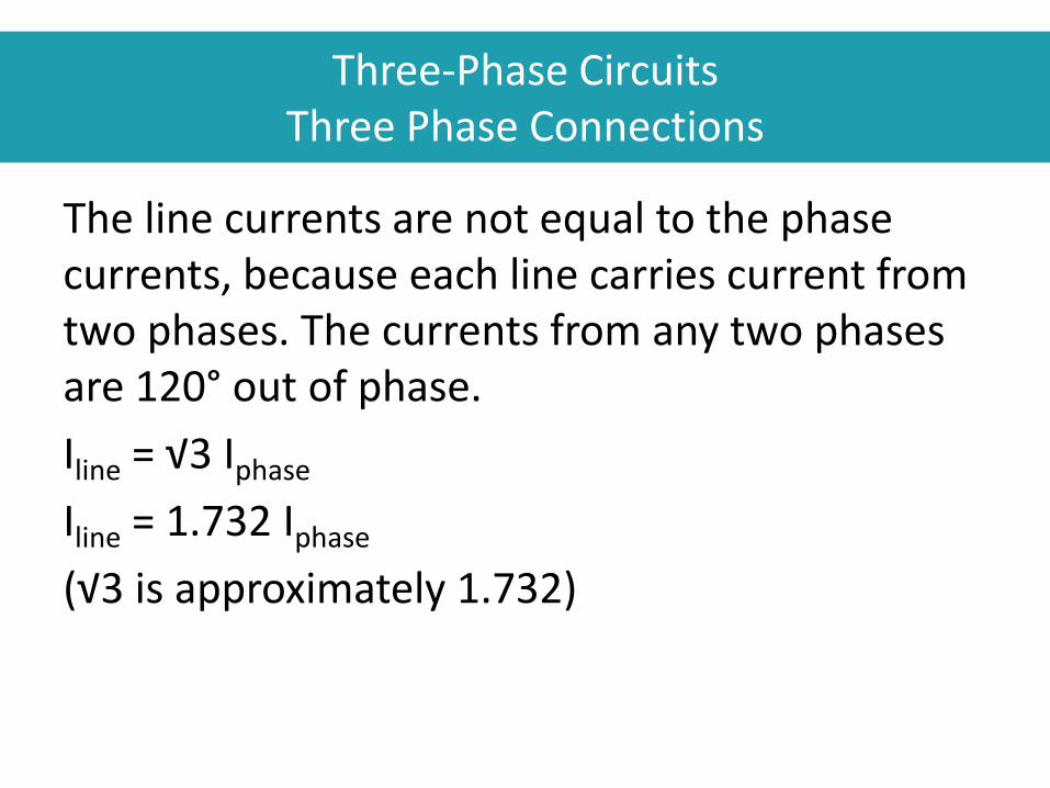
The line currents are not equal to the phase currents, because each line carries current from two phases. The currents from any two phases are 120° out of phase.
Iline = √3 Iphase
Iline = 1.732 Iphase
(√3 is approximately 1.732)
Three-Phase Circuits Three Phase Connections

“Delta” Connection
“A” Phase “B” Phase
“C” Phase
Three-Phase Circuits Three Phase Connections

Three-Phase Circuits Three Phase Connections

Three-Phase Circuits Three Phase Connections

Three-Phase Circuits Three Phase Connections

Three-Phase Circuits
Three Phase Connections

Three-Phase Circuits Three Phase Connections

Three-Phase Circuits Three Phase Connections
“WYE” Connection

Three-Phase Circuits Three Phase Connections
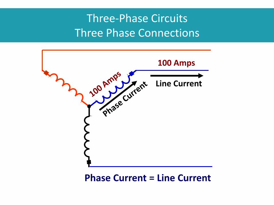
Three-Phase Circuits Three Phase Connections
100 Amps
Phase Current = Line Current

Three-Phase Circuits Three Phase Connections
13,200 Volts
Line Voltage = Phase Voltage x √3 = PV x 1.732
1.732 Vphase= VLine-Line

Three-Phase Circuits
Three Phase Connections

Electromechanics
• Definition
• Generators
• Motors
• Synchronous Condenser

Electromechanics Definition
Electromechanical Energy Conversion is used by generators and motors.
• This process transforms mechanical energy into electrical energy and vice versa

Electromechanics
Generators
A simple Generator

Electromechanics Motors
A simple Motor

Generators and Motors

Electromechanics Generators and Motors
A generator converts mechanical energy into electrical energy.
– A voltage is induced in stator conductors as the magnetic flux from the rotor moves past them
A motor converts electrical energy into rotary motion.
– Current-carrying conductors in the rotor experience a force at right angles to the magnetic field of the motor

Electromechanics
Generators

Electromechanics
Generators

Electromechanics Motors

Sychronous Condenser

Electromechanics Synchronous Condenser
A synchronous condenser is a large synchronous motor.
• A synchronous condenser is used to generate or absorb VARs
• Operators can control whether it produces or consumes VARs

Check Your Knowledge: Fundamentals of Electricity
1. A conductor is a material that has only a few free valance electrons that continually jump to other atoms. T/F?
2. What are two materials that are good electrical conductors?
3. An insulator is a material that has a large number of free valance electrons that continually jump to other atoms. T/F?
4. What are two materials that are good electrical insulators.
5. Whenever current flows in a conductor, what invisible force surrounds the conductor?
6. In an inductive circuit, does the current lead or lag the voltage?
7. What is impedance?
276
W E S T E R N E L E C T R I C I T Y C O O R D I N A T I N G C O U N C I L