module 3 with answers - quia – electrical workshop module 3: basic electrical components 3 3.1...
TRANSCRIPT

Electrical Workshop
Module 3: Basic Electrical Components
PREPARED BY
Academic Services Unit
August 2012
© Applied technology High Schools, 2012
ATE210 – Electrical Workshop
Module 3: Basic Electrical Components 2
Module 3: Basic Electrical Components
Module Objectives
Upon successful completion of this module, students should be able to:
1. Identify basic electrical components such as:
Lamps, motors and buzzers.
Resistors, LDRs, capacitors and inductors.
Diodes.
2. State the application of each component.
Module Contents:
Topic Page No.
3.1 Introduction 3
3.2 Basic Electrical Components 3
3.3 Components Coding 6
3.4 Class and Lab Activities 9
3.5 Review Exercise 14

ATE210 – Electrical Workshop
Module 3: Basic Electrical Components 3
3.1 Introduction Have you ever opened your personal computer (PC) or your radio from the inside? If
you tried so, have you seen the electrical boards with many components mounted on
them? Figure 3.1 shows an example of a PC electrical board with different
components. In this module, we will study these components and understand their
usages and applications.
Figure 3.1: PC Electrical Board
3.2 Basic Electrical Components
Component Symbol Function Picture
Lamp
Light Indicator
Motor
Motion Indicator
Buzzer
Sound Indictor

ATE210 – Electrical Workshop
Module 3: Basic Electrical Components 4
Component Symbol Function Picture
Resistor
Resistors limit the current flow
Variable Resistor
Variable resistors control the current in the circuit:
- Adjust lamp brightness - Adjust motor speed
They are also called potentiometers
LDR (Light Dependent Resistor)
LDRs are variable resistors where resistance value changes with light
ATE210 – Electrical Workshop
Module 3: Basic Electrical Components 5
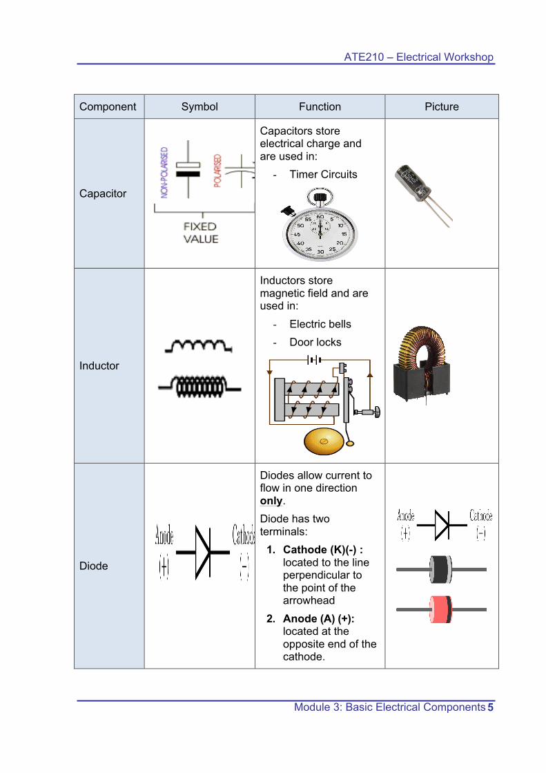
Component Symbol Function Picture
Capacitor
Capacitors store electrical charge and are used in:
- Timer Circuits
Inductor
Inductors store magnetic field and are used in:
- Electric bells - Door locks
Diode
Diodes allow current to flow in one direction only. Diode has two terminals:
1. Cathode (K)(-) : located to the line perpendicular to the point of the arrowhead
2. Anode (A) (+): located at the opposite end of the cathode.

ATE210 – Electrical Workshop
Module 3: Basic Electrical Components 6
3.3 Components Coding: 1. Resistance Coding: Resistors are specified by their resistance value and their
tolerance. One way to indicate the resistance value and tolerance is color code method, which is explained in Figure 3.2.
1. Resistance is measured in ohms (Ω) 2. Most resistors have 3 bands:
• The 1st band gives the first digit. • The 2nd band gives the second digit. • The 3rd band indicates the number of zeros. • The 4th band gives the tolerance
Figure 3.2 Resistance color code

ATE210 – Electrical Workshop
Module 3: Basic Electrical Components 7
• Exercises: State the resistor’s value and tolerance for the following resistors:
R = 470 Ω ± 10%
Yellow Violet Brown Silver
4 7 0 ±10 %
R = 25 Ω ± 5%
Red Green Black Gold
2 5 ±5 %
R = 72 Ω ± 5%
Violet Red Black Gold
7 2 ±5 %
R = 94000 Ω ± 10%
White Yellow Orange Silver
9 4 000 ±10%
R = 25000 Ω ± 10%
Red Green Orange Silver
2 5 000 ±10%
R = 65000 Ω ±5%
Blue Green Orange Gold
6 5 000 ±5 %

ATE210 – Electrical Workshop
Module 3: Basic Electrical Components 8
2. Capacitor Coding: Capacitors are usually specified by three quantities;
capacitor value, tolerance and voltage rating. A number code is often used
on small capacitors where printing is difficult.
• The 1st number is the 1st digit,
• The 2nd number is the 2nd digit
• The 3rd number is the number of zeros to give the capacitance in pF
• Ignore any letters - they just indicate tolerance and voltage rating.
• Example 1: You have a capacitor with "104" stamped on it.
- The first two digits are: 1 0
- The third digit is: 4 so add four zeros to the 1 0 à 1 0, 0 0 0 0 pF
• Exercises:
State the capacitance value for the following capacitors:
C = 1000 pF C=68000 pF C = 2200 pF
C = 150000pF C = 470pF C = 540pF
102 683 222
154 471 541
ATE210 – Electrical Workshop
Module 3: Basic Electrical Components 9
3.4 Class and Lab Activities:
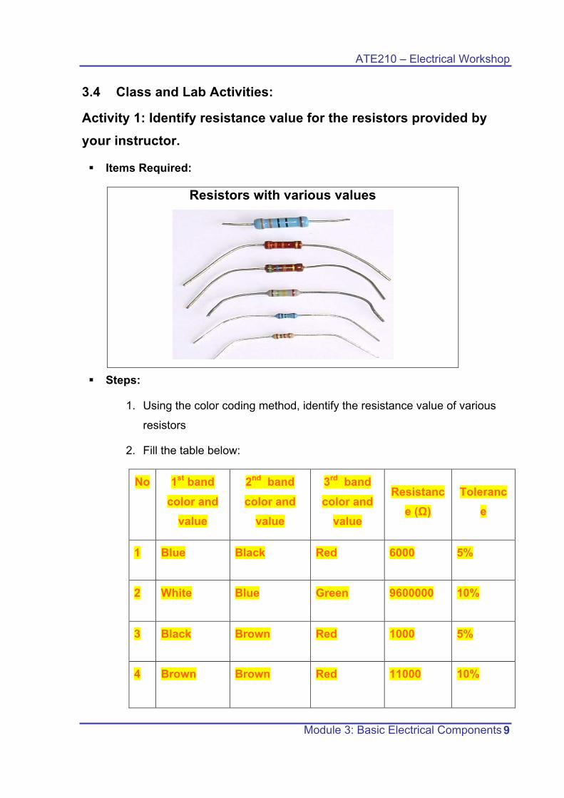
Activity 1: Identify resistance value for the resistors provided by your instructor.
§ Items Required:
Resistors with various values
§ Steps:
1. Using the color coding method, identify the resistance value of various
resistors
2. Fill the table below:
No 1st band color and
value
2nd band color and
value
3rd band color and
value
Resistance (Ω)
Tolerance
1 Blue Black Red 6000 5%
2 White Blue Green 9600000 10%
3 Black Brown Red 1000 5%
4 Brown Brown Red 11000 10%

ATE210 – Electrical Workshop
Module 3: Basic Electrical Components 10
Activity 2:
Light intensity control using potentiometer (variable resistor).
§ Items Required:
Potentiometer 9V Battery 9 V Light Bulb Alligator Clips
§ Steps:
Connect the following circuit:
Rotate the spindle of the potentiometer. What do you observe on the light
brightness?
The light will increase or decrease depending on the direction of the movement.
State an application of potentiometers
Light dimmers, speed control (fan), sound control (speakers).
ATE210 – Electrical Workshop
Module 3: Basic Electrical Components 11
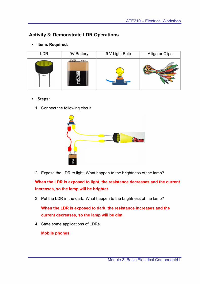
Activity 3: Demonstrate LDR Operations
§ Items Required:
LDR 9V Battery 9 V Light Bulb Alligator Clips
§ Steps:
1. Connect the following circuit:
2. Expose the LDR to light. What happen to the brightness of the lamp? When the LDR is exposed to light, the resistance decreases and the current increases, so the lamp will be brighter.
3. Put the LDR in the dark. What happen to the brightness of the lamp?
When the LDR is exposed to dark, the resistance increases and the current decreases, so the lamp will be dim.
4. State some applications of LDRs. Mobile phones
ATE210 – Electrical Workshop
Module 3: Basic Electrical Components 12
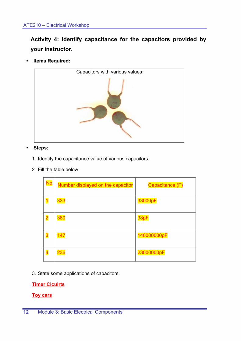
Activity 4: Identify capacitance for the capacitors provided by your instructor.
§ Items Required:
Capacitors with various values
§ Steps:
1. Identify the capacitance value of various capacitors.
2. Fill the table below:
No Number displayed on the capacitor Capacitance (F)
1 333 33000pF
2 380 38pF
3 147 140000000pF
4 236 23000000pF
3. State some applications of capacitors.
Timer Cicuirts
Toy cars

ATE210 – Electrical Workshop
Module 3: Basic Electrical Components 13
Activity 5: Draw the symbols for the following components:
Components Symbol
LDR
Diode
Variable Resistor
Capacitor
Resistor
Inductor
ATE210 – Electrical Workshop
Module 3: Basic Electrical Components 14
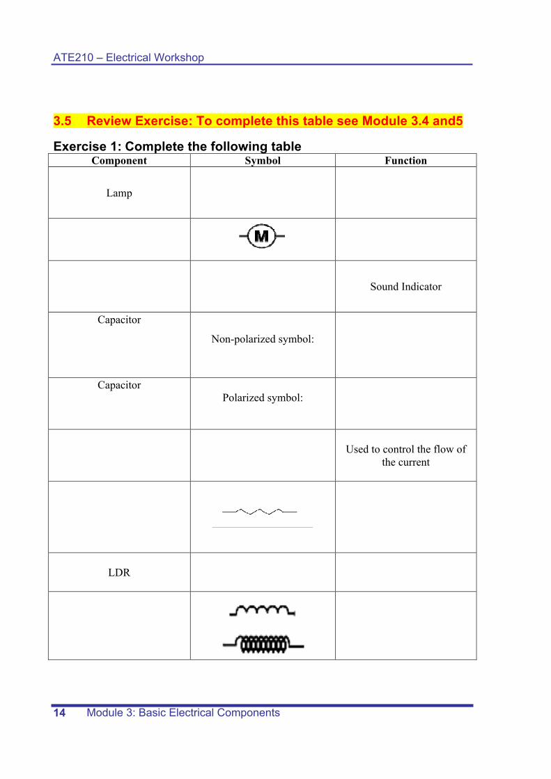
3.5 Review Exercise: To complete this table see Module 3.4 and5
Exercise 1: Complete the following table Component Symbol Function
Lamp
Sound Indicator
Capacitor
Non-polarized symbol:
Capacitor
Polarized symbol:
Used to control the flow of the current
LDR

ATE210 – Electrical Workshop
Module 3: Basic Electrical Components 15
Exercise 2:
• If the value of a capacitor is 1000 pf, what is the capacitor code that should be stamped on it? 103
• The value of the capacitor shown below is: 1540000pF
Exercise 3:
Draw the electrical symbol of the diode and mark the anode and cathode:
ATE210 – Electrical Workshop
Module 3: Basic Electrical Components 16
Exercise 4:
Complete the following:
• LDR stands for: Light dependent resistor
• When the LDR is exposed to light it has a low resistance.
• When the LDR is exposed to darkness it has a high resistance.
• An electrical component allows the current to flow in one direction only: diode
• An electrical component that stores magnetic field: inductor
• An electrical component that stores electrical charge: capacitor
• An electrical component that is used to adjust the lamp brightness: Variable Resistor
• An electrical component that is used to adjust the motor speed is Variable Resistor
•
• An electrical component that is used to limit the flow of current is: resistor