module 4 architecture development for dodaf 2.0 plan/module 4 architecture... · development...
TRANSCRIPT
Architecture Development
1 May 10, 2010 Version 1.0
Architecture Development
The architecture development chapter is where the DoDAF training course becomes more
technical. Learning about the DoDAF 2.0 viewpoints, views, and models means nothing without
the knowledge of architectural development. This chapter covers the 6 Step Architecture
development process, Architecture planning, Analytics and of course, presentation techniques.
This chapter covers the A‐Z of the architecture development process, without getting buried in
the details of merits and drawbacks of certain viewpoints. Keep the class focused on the larger
picture at this point in time. In addition, tailor this section to your audience. For example, if you
have mostly managers in this course, don’t go into detail about what an architect should know.
1. Methodologies
a. Methodology Based Approach to Architecture
b. 6‐Step Architecture Development process
2. What Does the DoD Manager (Decision‐Maker, Process‐Owner, Executive, or
Stakeholder) need to do?
3. What does the Architect do?
4. Enterprise Architecture
5. Scoping Architectures to be “fit‐for‐purpose”
6. Architecture Planning
7. Detailed Planning
8. Approaches to Architecture Development
9. Architecture‐Based Analytics
10. Architecture Presentation Techniques (utilize the diagrams in the appendix extensively
for this section)
11. Security
Architecture Development
2 May 10, 2010 Version 1.0
Methodologies
Methodology Based Approach to Architecture
6‐Step Architecture Development process
The methodology‐based approach to Architectural Description development in DoD draws on
the methodology originally introduced in DoDAF V1.5 and expands on that methodology to
highlight its use in a data‐driven, net‐centric architecture development environment. The
methodology represents best practices that have evolved over time, and can be utilized in
conjunction with, or as a replacement for other methodologies, as described below.
Methodology Based Approach to Architecture
Methodology Based Approach to Architecture
o Static Analyses
o Dynamic Analyses
o Experimentation
An architecture development methodology specifies how to derive relevant information about
an enterprise’s processes and business or operational requirements, and how to organize and
model that information. Architecture methods describe consistent and efficient ways to collect
data, organize the data in a particular grouping or structure, and store collected data for later
presentation and use in decision‐making processes. A methodology also provides a means for
replicating the steps taken to create an Architectural Description for a specific purpose later, by
another person or team with the expectation of achieving similar results.
In turn, through utilization of a method, it is possible to compare Architectural Descriptions
created under the same, or similar methods, evaluate how disparate Architectural Descriptions
can be linked to provide a higher‐level picture of a process or capability, and to analyze the
impact of future change. These analyses can include:
1. Static Analyses – can include capability audit, interoperability analysis, or functional
analysis. These analyses are often performed using simple analysis tools such as paper‐
based comparisons and database queries.
2. Dynamic Analyses – sometimes referred to as executable models, these analyses
typically examine the temporal, spatial, or other performance aspects of a system
through dynamic simulations. For example, these analyses might be used to assess the
Architecture Development
3 May 10, 2010 Version 1.0
latency of time sensitive targeting systems or conduct traffic analyses on deployed
tactical networks under a variety of loading scenarios.
3. Experimentation – the use of tactical capability requirements, such as the Coalition
Warrior Interoperability Demonstration (CWID), and various battle labs to provide the
ability to conduct human‐in‐the‐loop simulations of operational activities. Differing
degrees of live versus simulated systems can be deployed during these experiments and
there is a high degree of control over the experiment variables. These can be used for a
variety of purposes.
6‐Step Architecture Development Process
Step 1: Determine Intended Use of Architecture
Step 2: Determine Scope of Architecture
Step 3: Determine Data Required to Support Architecture Development
Step 4: Collect, Organize, Correlate, and Store Architectural Data
Step 5: Conduct Analyses in Support of Architecture Objectives
Step 6: Document Results in Accordance with Decision‐Maker Needs
See Page 2 of the Appendix, Figure 2.1, for a visual depiction of the 6‐Step Architecture
Development Process.
The 6‐step architecture development process described below is a generic, time‐tested
method, which can be utilized, in a wide range of architectural requirements through relatively
simple adaptation. The examples described within the steps provide information on
customization of the generic method for use in major departmental functions and operations.
NOTE: The methodology described is also applicable to development of SOA‐based
architectures. The steps described in the methodology, together with the requirements of the
toolset, techniques and notation desired, should be considered together when defining a
SOA. The Service Viewpoint provides specific models that are useful for services‐specific data
collection, and presentation models and documents that describe services.
If another method is desired, then utilization of the information contained in Architectural Data
and Models and the DM2 PES, provide the information needed for use in developing an
Architectural Description. When utilizing another method, reference to this methodology can
ensure adherence to the principles described in DoDAF V2.0, to maximize the potential for
reuse of essential data, and also to ensure conformance with DoDAF V2.0.
The process is data‐centric rather than product‐centric (e.g., it emphasizes focus on data, and
relationships among and between data, rather than DoDAF V1.0 or V1.5 products). This data‐
centric approach ensures concordance between views in the Architectural Description while
Architecture Development
4 May 10, 2010 Version 1.0
ensuring that all essential data relationships are captured to support a wide variety of analysis
tasks. The views created as a result of the architecture development process provide visual
renderings of the underlying architectural data and convey information of interest from the
Architectural Description needed by specific user communities or decision makers. The figure
above depicts this 6‐step process.
Architectural Description: It is important to note that the development of Architectural
Description is an iterative process and a unique one, in that every Architectural Description is:
Different in that architecture creation serves a specific purpose, and is created from a
particular viewpoint.
Serving differing requirements, necessitating different types of views to represent the
collected data.
Representative of a ‘snapshot in time’ (e.g., the Architectural Description may represent the
current view or baseline, or it may represent a desired view in some future time).
Changeable over time as requirements become more focused or additional knowledge
about a process or requirement becomes known.
The methodology is designed to cover the broadest possible set of circumstances, and also to
focus on the most commonly used steps by the architecture community.
Step 1: Determine Intended Use of Architecture
Defines the purpose and intended use of the architecture (“Fit‐for‐Purpose”); how the
Architectural Description effort will be conducted; the methods to be used in architecture
development; the data categories needed; the potential impact on others; and the process by
which success of the effort will be measured in terms of performance and customer
satisfaction. This information is generally provided by the process owner to support
architecture development describing some aspect of their area of responsibility (process,
activity, etc.).
A template for collection of high‐level information relating to the purpose and scope of the
Architectural Description, its glossary, and other information, has been developed for
registration of that data in DARS.
Step 2: Determine Scope of Architecture
The scope defines the boundaries that establish the depth and breadth of the Architectural
Description and establish the architecture’s problem set, helps define its context and defines
the level of detail required for the architectural content. While many architecture development
efforts are similar in their approach, each effort is also unique in that the desired results or
Architecture Development
5 May 10, 2010 Version 1.0
effect may be quite different. As an example, system development efforts generally focus first
on process change, and then concentrate on those automated functions supporting work
processes or activities. In addition to understanding the process, discovery of the system
functions is important in deciding how to proceed with development or purchase of
automation support.
Information collected for Architectural Descriptions describing services is similar to information
collected for Architectural Descriptions describing systems. For describing services,
Architectural Description will collect additional information concerning subscriptions, directory
services, distribution channels within the organization, and supporting
systems/communications web requirements.
Similar situations occur with Architectural Description development for joint operations. Joint
capabilities are defined processes with expected results, and expected execution capability
dates. The Architectural Descriptions supporting the development of these types of capabilities
usually require the reuse of data already established by the military services and agencies,
analyzed, and configured into a new or updated process that provides the desired capability.
Included are the processes needed for military service and/or agency response, needed
automation support, and a clear definition of both desired result and supporting performance
measures (metrics). These types of data are presented in models.
The important concept for this step is the clarity of scope of effort defined for the project that
enables an expected result. Broad scoping or unclear definition of the problem can delay or
prevent success. The process owner has the primary responsibility for ensuring that the scoping
is correct, and that the project can be successfully completed.
Clarity of scope can better be determined by defining and describing the data to be used in the
proposed Architectural Description in advance of the creation of views that present desired
data in a format useful to managers. Early identification of needed data, particularly data about
the Architectural Description itself, the subject‐matter of the proposed Architectural
Description, and a review of existing data from COIs, can provide a rich source for ensuring that
Architectural Descriptions, when developed, are consistent with other existing Architectural
Descriptions. It also ensures conformance with any data‐sharing requirements within the
Department or individual COIs, and conformant with the DM2.
An important consideration beginning with this and each subsequent step of the architecture
development process is the continual collection and recording of a consistent, harmonized, and
common vocabulary. The collection of terms should continue throughout the architecture
development process. As architectural data is identified to help clarify the appropriate scope of
the architecture effort, vocabulary terms and definitions should be disambiguated, harmonized,
Architecture Development
6 May 10, 2010 Version 1.0
and recorded in a consistent AV‐2 process documented in the “DoDAF V2.0 Architecture
Development Process for the DoDAF‐described Models” Microsoft Project Plan.
Analysis of vocabularies across different Architectural Descriptions with similar scope may help
to clarify and determine appropriate Architectural Description scope. Specific examples of data
identification utilizing the AV‐2 Data Dictionary construct are found in the DoDAF Journal.
Step 3: Determine Data Required to Support Architecture Development
The required level of detail to be captured for each of the data entities and attributes is
determined through the analysis of the process undergoing review conducted during the
scoping in Step 2. This includes the data identified as needed for execution of the process, and
other data required to effect change in the current process, (e.g., administrative data required
by the organization to document the Architectural Description effort). These considerations
establish the type of data collected in Step 4, which relate to the architectural structure, and
the depth of detail required.
The initial type of architectural data content to be collected is determined by the established
scope of the Architectural Description, and recorded as attributes, associations, and concepts
as described in the DM2. A mapping from DM2 concepts, associations, and attributes to
architecture models suggests relevant architectural views the architect may develop (using
associated architecture techniques) during the more comprehensive and coherent data
collection of Step 4. This step is normally completed in conjunction with Step 4, a bottom‐up
approach to organized data collection, and Architectural Description development typically
iterates over these two steps. As initial data content is scoped, additional data scope may be
suggested by the more comprehensive content of Architectural Views desired for presentation
or decision‐making purposes.
This step can often be simplified through reuse of data previously collected by others, but
relevant to the current effort. Access to appropriate COI data and other architecture
information, discoverable via DARS and the DMR, can provide information on data and other
architectural views that may provide useful in a current effort.
Work is presently underway within the Department to ensure uniform representation for the
same semantic content within architecture modeling, called Architecture Modeling Primitives.
The Architecture Modeling Primitives, hereafter referred to as Primitives, will be a standard set
of modeling elements, and associated symbols mapped to DM2 concepts and applied to
modeling techniques. Using the Primitives to support the collection of architecture content and,
in concert with the PES, will aid in generating common understanding and communication
among architects in regard to architectural views. As the Primitives concepts are applied to
Architecture Development
7 May 10, 2010 Version 1.0
more modeling techniques, they will be updated in the DoDAF Journal and details provided in
subsequent releases of DoDAF. When creating an OV‐6c in Business Process Modeling Notation
(BPMN), the Primitives notation may be used. DoD has created the notation and it is in the
DoDAF Journal. The full range of Primitives for views, as with the current BPMN Primitives, will
be coordinated for adoption by architecture tool vendors.
Step 4: Collect, Organize, Correlate, and Store Architectural Data
Architects typically collect and organize data through the use of architecture techniques
designed to use views (e.g., activity, process, organization, and data models as views) for
presentation and decision‐making purposes. The architectural data should be stored in a
recognized commercial or government architecture tool. Terms and definitions recorded are
related to elements of the (DM2).
Designation of a data structure for the Architectural Description effort involves creation of a
taxonomy to organize the collected data. This effort can be made considerably simpler by
leveraging existing, registered artifacts registered in DARS, to include data taxonomies and data
sets. Each COI maintains its registered data on DARS, either directly or through a federated
approach. In addition, some organizations, such as U.S. Joint Forces Command (JFCOM), have
developed templates, which provide the basis of a customizable solution to common problems,
or requirements, which includes datasets already described and registered in the DMR.
Examples of this template‐based approach are in the DoDAF Journal.
DARS provides more information that is specific, and guidance on retrieving needed data
through a discovery process. Once registered data is discovered, the data can be cataloged and
organized within a focused taxonomy, facilitating a means to determine what new data is
required. New data is defined, registered in DARS, and incorporated into the taxonomy
structure to create a complete defined list of required data. The data is arranged for upload to
an automated repository to permit subsequent analysis and reuse. Discovery metadata (i.e., the
metadata that identifies a specific Architectural Description, its data, views, and usage) should
be registered in DARS as soon as it is available to support discovery and enable federation.
Architects and data managers should use the DoD EA Business Reference Model (DoD EA BRM)
taxonomy elements as the starting point for their registration efforts. Additional discovery
metadata, such as processes and services may be required later, and should follow the same
registration process.
Step 5: Conduct Analyses in Support of Architecture Objectives
Architectural data analysis determines the level of adherence to process owner requirements.
This step may also identify additional process steps and data collection requirements needed to
Architecture Development
8 May 10, 2010 Version 1.0
complete the Architectural Description and better facilitate its intended use. Validation applies
the guiding principles, goals, and objectives to the process requirement, as defined by the
process owner, along with the published performance measures (metrics), to determine the
achieved level of success in the Architectural Description effort. Completion of this step
prepares the Architectural Description for approval by the process owner. Changes required
from the validation process, result in iteration of the architecture process (repeat steps 3
through 5 as necessary).
Step 6: Document Results in Accordance with Decision‐Maker Needs
The final step in the architecture development process involves creation of architectural views
based on queries of the underlying data. Presenting the architectural data to varied audiences
requires transforming the architectural data into meaningful presentations for decision‐makers.
This is facilitated by the data requirements determined in Step 3, and the data collection
methods employed during Step 4.
DoDAF V2.0 provides for models and views. DoDAF‐described Models are those models that
enable an architect and development team whose data has already been defined and described
consistent with the DM2. The models become views when they are populated with
architectural data. These models include those previously described in earlier versions of
DoDAF, along with new models incorporated from the MODAF, the NATO NAF, and TOGAF that
have relevance to DoD architecture development efforts.
Fit‐for‐Purpose Views are user‐defined views that an architect and development team can
create to provide information necessary for decision‐making in a format customarily used in an
agency. These views should be developed consistent with the DM2, but can be in formats (e.g.,
dashboards, charts, graphical representations) that are normally used in an agency for briefing
and decision purposes. An Architectural Description development effort can result in an
Architectural Description that is a combination of DoDAF‐described Models and Fit‐for‐Purpose
Views.
DoDAF does not require specific models or views, but suggests that local organizational
presentation types that can utilize DoDAF‐created data are preferred for management
presentation. A number of available architecture tools support the creation of views described
in this step. The PES provides the format for data sharing.
NOTE: DoDAF V2.0 does NOT prescribe a Physical Data Model, leaving that task to the software
developers who will implement the principles and practices of DoDAF in their own software
offerings.
Architecture Development
9 May 10, 2010 Version 1.0
What Does the DoD Manager (Decision‐Maker, Process‐Owner, Executive, or
Stakeholder) Need to Do?
See Page 3 in Appendix, Figure 2.2, for a visual depection of the the DoD manager needs to do.
Purpose and Scope
The DoD Manager identifies the Purpose and Scope for the Architectural Description and gains
agreement with the architect. Through the 6‐Step Architecture Development Process, the DoD
Manager needs to remain involved from end‐to‐end to support the Architectural Description
development.
Step 3.1
After the DoD Manager has determined the Purpose and Scope (Steps 1 and 2), they need to
review the Purpose and Scope with the architect. In order for the architecture to be “Fit‐for‐
Purpose”, the DoD Manager needs to provide the architect with the list of data needed and the
usage of that data (use‐cases). The DoD Manager, not the architect, is the subject matter
expert. The DoD Manager, in concert with the architect, will determine the problem to be
solved, the decisions to be made, and the corresponding data and information to be captured
and analyzed. These key responsibilities cannot be delegated to the architect.
Step 3.2
The DoD Manager reviews the DoDAF‐described Models and Fit‐for‐Purpose Views, Concepts,
Associations, and Attributes that, according to the architect, meet the data requirements and
use‐cases.
Step 4.1
The DoD Manager must assist or provide the data needed to enable the architecture collection
method to work.
Step 5.1
The DoD Manager needs to verify that the data collected meets their needs (uses) and is
sufficient to support the analysis that will be performed in Step 5.
Step 6.1
Architecture Development
10 May 10, 2010 Version 1.0
Based on data collected in Step 4 and the use‐cases, the DoD Manager determines the
appropriate methods of presentation of the “Fit‐for‐Purpose” views and to support their
decision processes.

Architecture Development
11 May 10, 2010 Version 1.0
What does the Architect Do?
Using DoDAF V2.0 and the DoDAF Journal, the architect needs to perform two key activities:
Develop the Architectural Description
Enable use of the Architectural Description in the solution implementation
Develop the Architectural Description
See page 4 in Appendix, Figure 2.3, for a visual depiction of what an Architect needs to do.
Once the Architectural Description Purpose and Scope are identified, what does the architect
need to do? Within the 6‐Step Architecture Development Process, in Step 3 the architect
determines the data needed to support the Architectural Description development.
In each step, the Meta‐model Groups referred to by the step is that data in the Meta‐model
Groups in the DoDAF Meta‐model. The figure below depicts the sub steps that the architect
needs to perform within the 6‐Step Architecture Development Process. Some of these sub steps
are performed in concert with the decision‐maker, but the architect has more steps than the
decision‐maker.
With the specific list of required:
DoDAF‐described Models,
Fit‐for‐Purpose Views,
DM2 Meta‐model Groups,
Concepts, Associations, and Attributes along with the:
Legacy Products,
User Requirements, and
Example Presentations
the architect and decision‐maker determines the appropriate presentations (Fit‐for‐Purpose
Views) and data for the identified “Fit‐for‐Purpose” needs that will meet the decision‐maker’s
purpose and support their decision processes.
The results of this sub‐step should support the presentations (Fit‐for‐Purpose Views) that will
be created in Step 6 of the 6‐Step Architecture Development Process. The DoDAF V2.0
Architecture Development Process for the DoDAF‐described Models in the DoDAF Journal
Architecture Development
12 May 10, 2010 Version 1.0
presents a non‐prescriptive set of tasks to develop DoDAF‐described Models in a Microsoft
Project Plan.
Step 3.1
Using the DM2 Concepts, Associations, and Attributes Mapping to DoDAF‐described Models in
Mappings to DM2 Concepts, the architect determines the DoDAF‐described Models needed,
based on the concepts required to satisfy the architecture’s purpose and scope (from Step 1
and 2 of the 6‐Step Architecture Development Process). The architect also determines the Fit‐
for‐Purpose Views needed, also based on the concepts required to satisfy the architecture’s
purpose and scope.
Step 3.2
After determining the DoDAF‐described Models and Fit‐for‐Purpose Views required, the
architect reviews the:
DM2 Conceptual Data Model
DM2 Logical Data Model
DM2 Concepts, Associations, and Attributes
DoDAF Meta‐model Data Dictionary
Step 4.1
With the concepts identified in the Architectural Description’s Purpose and Scope (from Step 1
and 2 of the 6‐Step Architecture Development Process), the required DoDAF‐described Models
and Fit‐for‐Purpose Views, the available DM2 metadata, the architect determines the specific
architecture DM2 Meta‐model Groups, concepts, associations, and attributes that need to be
collected for the Architecture Development Process. The tables in the Method subsections of
Section 2, Meta‐model Data Groups, identify the specific data.
Step 4.2
The architect assembles the list of required DoDAF‐described Models and Fit‐for‐Purpose
Views, DM2 Meta‐model Groups, Concepts, Associations, and Attributes. This provides the list
of architectural data that needs to be collected, organized, correlated, and stored as part of
Step 4 of the 6‐Step Architecture Development Process.
Step 4.3
Using the identified Meta‐model Groups in the DM2, the architect determines the method to
collect the data. With the specific list of required DoDAF‐described Models, Fit‐for‐Purpose
Architecture Development
13 May 10, 2010 Version 1.0
Views, DM2 Meta‐model Groups, Concepts, Associations, and Attributes, the architect
determines the appropriate collection methods for the “Fit‐for‐Purpose” needs. The results of
this sub‐step should guide the collection methods that will be performed in Step 4 of the 6‐Step
Architecture Development Process.
Step 5.1
Using the identified Meta‐model Groups in the DM2, the architect determines the usage of the
data. With the specific list of required DoDAF‐described Models, Fit‐for‐Purpose Views, DM2
Meta‐model Groups, Concepts, Associations, and Attributes, the architect determines the
appropriate usage to satisfy the identified “Fit‐for‐Purpose” needs. The architect needs to
determine the “Fit‐for‐Purpose” use of the architectural data that will meet the decision‐
maker’s purpose and support the decision processes, including the analysis that will need to be
performed in Step 5 of the 6‐Step Architecture Development Process. The results of this sub
step should support the analysis that will be performed in Step 5 of the 6‐Step Architecture
Development Process. Architectural Description analysis is key to proper use of an architecture
by its stakeholders. Such analysis should be the joint responsibility of the stakeholders and the
architect to ensure it answers the stakeholders’ questions.
Step 6.1
Using the identified Meta‐model Groups in the DM2, the architect and decision‐maker
determines the presentations of the data.
Using Architectural Metadata
In addition, as the architecture is being developed, architecture metadata can be used (and
updated) to support various processes and to populate architecture resources for
implementation. One of the Net‐Centric Data Strategy goals supported is to enable the
architecture to be Discoverable as a reusable Architecture Resource. The Figure 2.4 in the
Appendix, on page 5, illustrates the potential uses of architecture metadata for the processes
they can support and the architecture resources that can be populated from the metadata
captured in an architecture repository. It is important to note that architecture metadata can
be used throughout the development process, not just at the end of the architecture effort.
The architecture metadata can support:
Defense Acquisition System process with Project metadata.
Planning, Programming, Budgeting, and Execution (PPBE) process with Cost metadata
Information Support Plan (ISP) process with Capability metadata.
Architecture Development
14 May 10, 2010 Version 1.0
Systems Design and Systems Engineering processes with various metadata, e.g., capability,
activity, processes, systems, services, cost, project, data, and taxonomies.
Service description, service port, and service Resource Flow metadata is used to populate a
Service Registry.
AV‐2 metadata is used to create DDMS data catalog entries for authoritative sources.
Resource Flow and Physical Schema metadata is used to populate the Metadata Registry.
DoD Information Technology Portfolio Repository (DITPR) population with System data.
Architecture Development
15 May 10, 2010 Version 1.0
Enterprise Architecture
Introduction and Overview
Transition Planning
Federated Approach to DoD Architecture Management
Tiered Accountability
DoD Architecture Enterprise Services
Within DoD, Enterprise Architecture (EA) has been seen for many years as providing product‐
oriented insight into a wide range of data, programs, and activities, organized through
Communities of Interest (COI). The data‐centric approach to DoDAF V2.0 is designed to
facilitate the reuse and sharing of COI data. Since DoDAF provides the conceptual, logical, and
PES but does not otherwise prescribe the configuration of the product composition, architects
and stakeholders are free to create their views of data that best serve their needs.
Introduction and Overview
An Architectural Description is a strategic information asset that describes the current and/or
desired relationships between an organization’s business, mission and management processes,
and the supporting infrastructure. Architectural Descriptions define a strategy for managing
change, along with transitional processes needed to evolve the state of a business or mission to
one that is more efficient, effective, current, and capable of providing those actions needed to
fulfill its goals and objectives. Architectural Descriptions may illustrate an organization, or a part
of it, as it presently exists; any changes desired (whether operational or technology‐driven); and
the strategies and projects employed to achieve the desired transformation. An Architectural
Description also defines principles and goals and sets direction on issues, such as the promotion
of interoperability, intra‐, and interagency information sharing, and improved processes, that
facilitate key DoD program decisions.
Such support extends beyond details or summaries of operational and systems solutions, and
includes program plans, programmatic status reporting, financial and budget relationships, and
risk management. In addition to detailed views of individual solutions, the framework supports
the communication of enterprise‐wide views and goals that illustrate the context for those
solutions, and the interdependencies among the components. Beyond the solution space,
standard mechanisms for communicating program plans, financial information, and project
status are established so that executives and managers can evaluate and direct their programs.

Architecture Development
16 May 10, 2010 Version 1.0
The DoD EA is an Architectural Description that is an enterprise asset used to assess alignment
with the missions of the DoD enterprise, to strengthen customer support, to support capability
portfolio management (PfM), and to ensure that operational goals and strategies are met.
The DoD EA is shown in Figure 2.5, on page 6 of the Appendix.
The DoD EA is comprised of DoD architecture policy, tools, and standards, DoD‐level
Architectural Descriptions like the DoD Information Enterprise Architecture (DoD IEA), DoD‐
level Capability Architectural Descriptions, and Component Architectural Descriptions. Its
purposes are to guide investment portfolio strategies and decisions, define capability and
interoperability requirements, provide access to Segment architecture information, to establish
and enforce standards, guide security and information assurance requirements across the
Department of Defense, and provide a sound basis for transition from the existing DoD
environment to the future. The DoD EA is a federation of Architectural Descriptions with which
Solution Architectural Descriptions must conform. Its content includes but is not limited to
rules, standards, services and systems lifecycle information needed to optimize and maintain a
process, or part of a process that a self‐sufficient organization wants to create and maintain by
managing its IT portfolio. The DoD EA provides a strategy that enables the organization to
support its current operations while serving as the roadmap for transitioning to its target
environment. Transition processes include an organization’s PfM, PPBE, and EA planning
processes, along with services and systems lifecycle methodologies.
The JCA portfolios describe future, required operational, warfighting, business, and Defense
intelligence capabilities, together with the systems and services required. They provide the
organizing construct for aligning and federating DoD EA content to support the Department
portfolio management structure. The description of the future DoD operating environment and
associated capability requirements represent the target architecture of the DoD EA. These are
time‐phased as determined by functional owners and JCA developers.
Migration in a net‐centric operating environment from the “As‐Is” to the “To‐Be” requires that
the DoD Information Environment Architecture (DoD IEA) and the Net‐Centric strategies act as
uniform references for, and guide the transition sequence to ensure that both
operational/business capabilities and IT capabilities, as required, are properly described. Policy
is being developed by the DoD CIO to describe how federation will be used to mature the DoD
EA as well as its relationship to federated, solution Architectural Descriptions.
Transition Planning
As discussed above, one major impetus for creating and using Architectural Descriptions is to
guide acquisition and development of new enterprises, capabilities and systems or
Architecture Development
17 May 10, 2010 Version 1.0
improvements to existing ones. Earlier versions of DoDAF addressed this need exclusively using
“As‐Is” and “To‐Be” Architectural Descriptions, along with a Systems and/or Services
Technology Forecast. The “As‐Is” and “To‐Be” concepts are time‐specific snapshots of DoDAF
views that initially served as the endpoints of a transition process. However, this transition
strategy has several potential pitfalls, to include the difficulty in accurately representing the
“As‐Is” starting point where legacy systems are sometimes poorly documented, and processes
are largely undefined. There is also the consideration that long‐term goals are often very
flexible, resulting in flux in the “To‐Be” version.
Since the “As‐Is” and “To‐Be” Architectural Descriptions are time‐specific versions of similar
sets of data with similar viewpoints, transition planning is able to chart an evolutionary path
from the “As‐Is” to its corresponding “To‐Be” architectural vision given a clear understanding of
the expected outcomes or objectives through some future (perhaps undefined) future point. It
is expected that the To‐Be Architectural Descriptions will change over time as Departmental
priorities shift and realign.
Federated Approach to DoD Architecture Management
The Department has adopted a federated approach to distributed architectural data collection,
organization, and management among the Services, Agencies and COIs as its means of
developing the DoD Enterprise Architecture, with a virtual rather than physical data set
described through supporting documentation and architectural views. This approach provides
increased flexibility while retaining significant oversight and quality management services at the
Departmental level. Detailed guidance on the DoD Federation approach will be contained in
DoDD 8210, “Architecting the DoD Enterprise.”
Tiered Accountability
Tiered Accountability (TA) is the distribution of authority and responsibility to a DoD
organization for an element of the DoD EA. Under TA, DoD is defining and building enterprise‐
wide capabilities that include data standards, business rules, enabling systems, and an
associated layer of interfaces for Department, specified segments of the enterprise (e.g., JCA,
DoD Components), and Programmatic solutions. Each tier has specific goals, as well as
responsibilities to the tiers above or below them.
Architectural Descriptions are categorized when developed to facilitate alignment (mapping
and linking), cataloging, navigating, and searching disparate architecture information in a DoD
registry of holdings. All Architectural Descriptions developed by the tiers should be federated,
as described in the DoD Federation Strategy.
Architecture Development
18 May 10, 2010 Version 1.0
Alignment in the tiers is required for the DoD EA to be discoverable, shareable, and
interoperable. Architectural Descriptions can also support many goals within the tiers, each of
which may imply specific requirements for structure, content, or level of detail. Alignment
decisions should balance the interdependence of Architectural Descriptions with the need for
local flexibility to address local issues. Alignment describes the minimum constraints needed to
ensure consistency across architecture levels. Architectural Descriptions often relate at some
‘touch point’ to other Architectural Descriptions on the same level, level(s) above, or level(s)
below, and should be discovered and utilized in the development of Architectural Descriptions
to ensure that appropriate linkages are created and maintained. The need to plan for them
implies that each Architectural Description sharing a touch‐point should be available to
architects on both sides. The DMR for data and the DARS for architecture registration facilitate
the ability to discover and utilize architectural data, with the caveat that any touch‐points
within the purview of an established COI adhere to COI guidance.
DoD Architecture Enterprise Services
The next generation of DoD Enterprise Architectures will be constructed by employing a set of
DoD Architecture Enterprise Services (DAES) for registering, discovering, aligning, translating,
and utilizing architectural data, and derived information to support key DoD decision processes
through implementing the concepts of the DoD Net‐Centric Strategies. DAES will be
implemented using Web Services, in which specific content and/or functionality is provided by
one user for others, many of whom may be unknown to the provider. An Operational Resource
Flow Description (A redesigned Operational Viewpoint 2 (OV‐2) DoDAF‐described Model) has
been retained in DoDAF V2.0 to describe those services that can be discovered and subscribed
from one or more specific sources and delivered to one or more known or unknown
subscribers.
Registration of architectures, one of the goals of the NCDS , is the first step toward enabling
discovery of architecture metadata. DAES includes a registration service to register the
metadata (through the DMR), and a method to describe the purpose and scope of an
Architectural Description (through DARS). The registration service will enable cataloging of
Architectural Descriptions in federated repositories, and, once complete, Architectural
Descriptions are ‘available’ for discovery. When an Architectural Description is discoverable, it
can be aligned to, linked to, or re‐used by other Architectural Descriptions. The discovery
service enables users to execute a federated search for architecture holdings meeting specified
search parameters.
Alignment to the Federal Enterprise Architecture
Architecture Development
19 May 10, 2010 Version 1.0
The OMB established the Federal Enterprise Architecture (FEA) program in 2003 to build a
comprehensive business‐driven blueprint of the entire Federal Government. OMB’s Circular A‐
11 requires that Cabinet‐level agencies, including the DoD, link their budget submissions to the
FEA, and annually evaluates those submissions through the Enterprise Architecture Assessment
Program, which establishes an evaluation score for overall agency progress.
The core principles of the FEA program are:
Business‐driven approach.
Promote collaboration of effort and reuse.
Improve efficiency and effectiveness of business operations through the use of enterprise
architecture for the capital investment process.
Demonstrate cost savings and cost avoidance through improved core processes, and cross‐
agency sharing and mutual investment.
DoD leverages the FEA construct and core principles to provide the Department with the
enterprise management information it needs to achieve its own strategic transformation goals
and respond to upward reporting requirements of OMB. The primary objective is to improve
DoD performance, using EA, by providing a framework for cross‐mission analysis and
identification of gaps and redundancies; and by developing transition plans and target
architectures that will help move DoD to the net‐centric environment.
Several Federal and DoD‐specific EA artifacts exist that describe enterprise‐level management
information. These include:
The President’s Management Agenda.
OMB A‐11 Exhibit 300 submissions.
OMB FEA Practice Guidance.
OMB EA Assessment Guide.
OMB FEA Reference Models.
DoD EA Reference Model (RM) Taxonomy.
DoD EA Consolidated RM.
DoD EA Transition Strategy.
DoD Segment Architectures.
DoD EA Self‐Assessment.
DoD Architecture Federation Strategy.
Architecture Development
20 May 10, 2010 Version 1.0
These artifacts facilitate the alignment with the FEA, contribute to a broader understanding of
architecture alignment, provide a basis for federated Architectural Descriptions, promote a
more efficient and effective use of assets, and ultimately lead to better decision‐making.
When developing architectures, particularly at the Departmental and Component levels,
alignment with the FEA is accomplished by utilizing the Federal Enterprise Architecture‐
Consolidated Reference Model (FEA‐CRM) documents together with DoD documents and
references as a basis for defining processes, data, services, and technical standards. As an
example, when a process owner determines that an Architectural Description is needed for
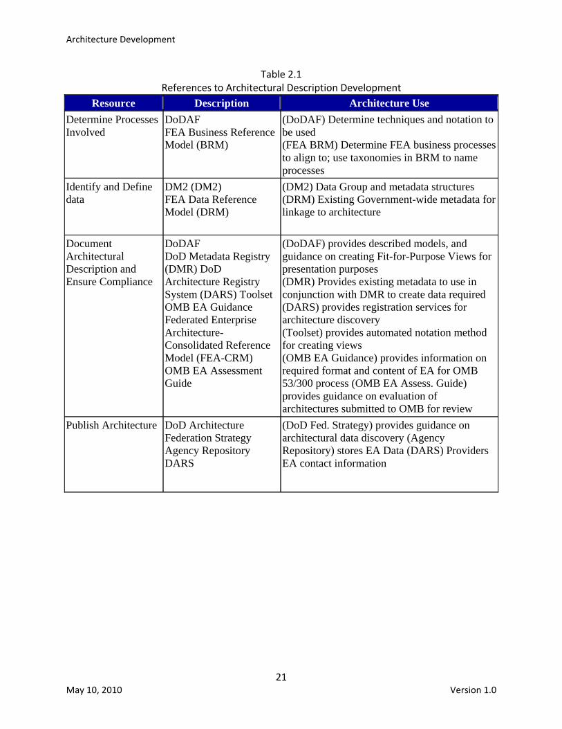
some specific purpose, the first references to use are as shown in Table 2.1 below, as well as
other Architectural Descriptions above and below the level of the Architectural Description
under development. The DoD‐level information is contained in the DoD EA Reference Models,
along with the implementing guidance, standards, and descriptions of Department‐wide
information that is mapped to the FEA‐CRM in accordance with the FEA construct.
Architecture Development
21 May 10, 2010 Version 1.0
Table 2.1 References to Architectural Description Development
Resource Description Architecture Use
Determine Processes Involved
DoDAF FEA Business Reference Model (BRM)
(DoDAF) Determine techniques and notation to be used (FEA BRM) Determine FEA business processes to align to; use taxonomies in BRM to name processes
Identify and Define data
DM2 (DM2) FEA Data Reference Model (DRM)
(DM2) Data Group and metadata structures (DRM) Existing Government-wide metadata for linkage to architecture
Document Architectural Description and Ensure Compliance
DoDAF DoD Metadata Registry (DMR) DoD Architecture Registry System (DARS) ToolsetOMB EA Guidance Federated Enterprise Architecture-Consolidated Reference Model (FEA-CRM) OMB EA Assessment Guide
(DoDAF) provides described models, and guidance on creating Fit-for-Purpose Views for presentation purposes (DMR) Provides existing metadata to use in conjunction with DMR to create data required (DARS) provides registration services for architecture discovery (Toolset) provides automated notation method for creating views (OMB EA Guidance) provides information on required format and content of EA for OMB 53/300 process (OMB EA Assess. Guide) provides guidance on evaluation of architectures submitted to OMB for review
Publish Architecture DoD Architecture Federation Strategy Agency Repository DARS
(DoD Fed. Strategy) provides guidance on architectural data discovery (Agency Repository) stores EA Data (DARS) Providers EA contact information
Architecture Development
22 May 10, 2010 Version 1.0
Scoping Architectures to be “Fit‐for‐Purpose”
Establishing the scope of an architecture is critical to ensuring that its purpose and use are
consistent with specific project goals and objectives. The term “Fit‐for‐Purpose” is used in
DoDAF to describe an architecture (and its views) that is appropriately focused (i.e., responds to
the stated goals and objectives of process owner), is useful in the decision‐making process, and
responds to internal and external stakeholder concerns. Meeting intended objectives means
those actions that either directly support customer needs or improve the overall process
undergoing change. The architect is the technical expert who translates the decision‐maker’s
requirements into a set of data that can be used by engineers to design possible solutions. At
each tier of the DoD, goals and objectives, along with corresponding issues that may exist
should be addressed according to the established scope and purpose, (e.g., Departmental,
Capability, SE, and Operational), as shown in the notional diagram, Figure 2.6, on page 7 of the
Appendix.
Establishing a scope for an architecture effort at any tier is similarly critical in determining the
architecture boundaries (Purpose and Use expected), along with establishing the data
categories needed for analysis and management decision‐making. Scope also defines the key
players whose input, advice, and consensus is needed to successfully architect and implement
change (i.e., Stakeholders, both internal and external). Importantly, scope also determines the
goals and objectives of the effort, consistent with both boundaries and stakeholders; since
goals and objectives define both the purpose for architecture creation and the level of the
architecture. Establishing the scope of an effort also determines the level of complexity for data
collection and information presentation.
Architecture development also requires an understanding of external requirements that may
influence architecture creation. An architecture developed for an internal agency purpose still
needs to be mappable, and consistent with, higher level architectures, and mappable to the
DoD EA. For some architecture developments, consideration must be given in data collection
and graphical presentation to satisfaction of other external requirements, such as upward
reporting and submission of architectural data and models for program review, funding
approval, or budget review due to the sensitivity or dollar value of the proposed solution. This
site contains guidance on data collection for specific views required by instruction, regulation,
or other regulatory guidance (i.e., Exhibit 53, or Exhibit 300 submissions; OMB Segment
architecture reviews, or interoperability requirements).
Architecture scoping must facilitate alignment with, and support the decision‐making process
and ultimately mission outcomes and objectives as shown in Figure 2.7 on page 7 of the

Architecture Development
23 May 10, 2010 Version 1.0
Appendix. Architectural data and supporting views, created from organizing raw data into
useful information, and collected into a useful viewpoint, should enable domain experts,
program managers, and decision makers to utilize the architecture to locate, identify, and
resolve definitions, properties, facts, constraints, inferences, and issues, both within and across
architectural boundaries that are redundant, conflicting, missing, and/or obsolete. DoDAF V2.0
provides the flexibility to develop both Fit‐for‐Purpose Views (User‐developed Views) and views
from DoDAF‐described Models to maximize the capability for decision‐making at all levels.
Figure 2.7 on page 7 of the Appendix shows how the development of architectures supports the
management decision process. In this case, the example shows how an architecture and the use
of it in analysis can facilitate the ability to determine and/or validate mission outcome.
Analysis also uncovers the effect and impact of change (“what if”) when something is redefined,
redeployed, deleted, moved, delayed, accelerated, or no longer funded. Having a disciplined
process for architecture development in support of analytics will produce quality results, not be
prone to misinterpretations, and therefore, be of high value to decision makers and mission
outcomes.

Architecture Development
24 May 10, 2010 Version 1.0
Architecture Planning
Defining the Enterprise
The Enterprise‐level architecture
Solution Architectures
Architecture Management
Architecture Development
Architecture Lifecycle and Architecture Governance
Architecture Utilization
Architecture Maintenance
Architecture Compliance Reviews
User Support
Training
Communications Planning
Quality Planning
Risk Management
Defining the Enterprise
In a generic sense, an enterprise is any collection of organizations that has a common set of
goals and/or a single bottom line. An enterprise, by that definition, can encompass a Military
Department, DoD as a whole, a division within an organization, an organization in a single
location, or a chain of geographically distant organizations linked by a common management or
purpose. An enterprise today is often thought of as an extended enterprise where partners,
suppliers, customers, along with their activities and supporting systems, are included in the
Architectural Description.
Government agencies may comprise multiple enterprises, and there may be separate
enterprise architecture, or Architectural Description projects. However, the projects often have
much in common about the execution of process activities and their supporting information
systems, and they are all linked an enterprise architecture. Architectural description
development in conjunction with the use of a common architecture framework, which
describes the common elements of Architectural Descriptions, lends additional value to the
effort, and provides a basis for the development of an architecture repository for the
integration and reuse of models, designs, and baseline data.
Architecture Development
25 May 10, 2010 Version 1.0
The Enterprise‐level Architecture
Enterprise‐level Architectural Descriptions in DoD are generally created under the responsibility
and authority of a senior‐level official within the Department, Component, Organization,
Agency, or the program office responsible for development of JCAs. As an enterprise‐level
effort, it is expected that all of the major processes are documented and described, even if a
specific project involves only a more limited subset of processes or activities. That way,
subsequent Architectural Description efforts can build on previous efforts to ensure the
integration and extension of the enterprise is not compromised. Enterprise‐level Architectural
Descriptions usually exhibit breadth rather than depth. Since this Architectural Description is
the 'capstone', or highest level of an Architectural Description, on which others will build, it is
especially important that processes, which relate to each other, either through interaction of
activities, or the use of data by internal and external stakeholders, are identified or
documented.
Solution Architectures
The solution‐architecture is scoped to include all major activities that are associated with an
identified solution for a capability gap in response to a specific requirement. This solution may
contain links to one or programs which require the data and/or outputs produced by the
specified the solution identified to fill a specified gap.
Architecture Management
Architectural Descriptions are designed to describe the data on an organization or
program/capability that will support continuing managing decision‐making over time. Creation
of Architectural Descriptions and their management follow an established lifecycle that is
similar to those other resources that have well‐described lifecycles. OMB Circular A‐130
describes the lifecycle as:
Develop
Use
Maintain
These phases recognize discreet actions that occur at various times, all designed to ensure that
architectural data can be collected and later reused for management decision‐making and
reporting.
Architecture Development
26 May 10, 2010 Version 1.0
Architecture Development
Architectural Descriptions are developed to represent either the state of an activity at a
specified time (i.e., baseline architecture) or the results of change in an activity that will occur
over some future time (i.e., "To‐Be" or future architecture). Enterprise architectures (usually
with Departmental, Capability, Segment, or Component content) are initially created to create a
common context needed to understand the organization and operations of high‐level processes
under their control.
Solution Architectural Descriptions collect data that is specific to their program or capability,
and data necessary to link to both the higher‐level Architectural Descriptions with which they
share common parentage, and any lower‐level Architectural Descriptions, which describe in
more detail particular aspects of the program or JCA.
Visualization of data provides a unique perspective of data from the viewpoint needed for
decision‐making. That may be a commander/director, action officer, system developer, data
administrator, user, or anyone else executing some part of the architected process. More
discussion of data collection and visualization is contained in the Logical data Model.
Architecture Lifecycle and Architecture Governance
Architectural Description development is only one phase of an overall architecture lifecycle,
similar to other process maturity and change lifecycles. One such lifecycle, the Architecture
Governance, Implementation, and Maturity Cycle, shown in Figure 2.8, on page 8 of the
Appendix, can be used to illustrate this point. This lifecycle relies on the commonly used Plan‐
Do‐Check‐Act (PDCA) governance method.
Architecture Utilization
The ultimate success of an Architectural Description effort lies in the ability to use architectural‐
related data to support decisions for change within the organization. While Architectural
Description development is generally accomplished as a project, accomplished through a team
trained for that purpose, the results of the Architectural Description development, to be
effective over the longer term, need to be adopted as the common, normal mode of
performing the organization's business.
The enterprise architecture, as a corporate asset, should be managed like any other asset, and
reinforced by management as a key part of the formal program that results in decision‐making.
Achieving that level of acceptance occurs only when Architectural Descriptions are created that
reflect reality (e.g., baseline), or planned change/growth (e.g., "To‐Be", or target).
Architecture Development
27 May 10, 2010 Version 1.0
Successful execution of the EA development process in an agency‐wide endeavor requires
management direction and support, allocation of resources, continuity, and coordination.
Creating an EA program calls for sustained leadership and strong commitment. It also requires
buy‐in by the agency head, senior leadership, and early designation of a lead architect. These
leaders and the supporting EA Team are the first level of support for institutionalizing the
results of the effort.
When architectural data and views are constructed and organized in a way that they are
understood, accepted, and utilized in daily activities, they facilitate decision‐making. To achieve
optimal success, architectural views and data must meet standards that facilitate reuse by
others whose activities border on, or replicate activities, services and systems already
documented by architectural data and products. To that end, data collection must adhere to
the standards set by the COI, or other recognized authority so that the data can be registered
for, and used by others.
Architecture Maintenance
Changes in an organization supported by Architectural Description development will achieve
institutionalization only when the senior leadership agrees with, supports, encourages,
reinforces, and adopts the results of the Architectural Description effort. Ideally, a member of
the Senior Leadership Team should be designated as the 'champion' of the change effort, and
should work with the process owner to ensure that institutionalization occurs Employees, who
actually perform the daily activities described in the Architectural Description, must be
represented in the Architecture Development Team and contribute to the overall data
collection and view creation.
Architecture Compliance Reviews
Architectural description compliance reviews are a key part of the validation and verification
(V&V) process ongoing throughout the Architectural Description development effort. A
compliance review is a type of review that analyzes whether Architectural Description
developers are progressing according to the specifications and requirements developed for the
Architectural Description effort by the process owner. The goals of an architecture compliance
review include:
Identifying errors in the Architectural Description early to reduce the cost and risk of
changes required later in the project. These error‐catching actions will reduce cost and
schedule slips, and will quickly realize business objectives.
Ensuring the application of best practices to Architectural Descriptions work
(Development, use, and maintenance).
Architecture Development
28 May 10, 2010 Version 1.0
Providing an overview of the compliance of architecture to mandated enterprise
standards.
Identifying and communicating significant architectural gaps to supplier and service
providers.
Communicating to management the status of technical readiness of the project.
Utilization of architecture compliance reviews as an integral part of the development process
ensures that utilization of architectural data and views later will be in conformance with
applicable requirements. A more in‐depth discussion of the compliance review process is
contained in the DoDAF Journal.
OMB Architecture Assessment
The OMB requires departments and independent agencies to submit a self‐assessment of their
enterprise architecture programs in February of each year. For DoD, this applies at the
Department level. The self‐assessment is performed in three EA capability areas: completion of
the EA, use of the EA and results, and utilization of the OMB Federal Enterprise Architecture
program EA Assessment Framework. Specifics of the DoD/OMB architecture self‐assessment
are described in the DoDAF Journal.
GAO Architecture Assessment
The Government Accountability Office (GAO) periodically requires all departments and
independent agencies to submit a self‐assessment of the maturity of the management of their
EA programs. In addition, GAO may perform their own review and assessment of architecture
efforts associated with large‐scale programs. In certain cases, GAO expects an agency to
establish an independent quality assurance process for a large‐scale architecture to determine
whether it meets quality criteria such as those identified earlier in this page. Specifics of the
DoD/GAO architecture self‐assessment are described in the DoDAF Journal. The Enterprise
Architecture Management Maturity Framework (EAMMF) can also be used for this purpose.
User Support
User support is the service that each enterprise unit provides its users, both internally and
externally to the enterprise, as described in the architectural data and views.
Training
It is the responsibility of agency executive management to institutionalize the control structures
for the EA process, as well as for the agency Capital Planning & Investment (CPIC) and Shelf Life
Code (SLC) processes. For each decision‐making body, all members should be trained, as
Architecture Development
29 May 10, 2010 Version 1.0
appropriate, in the EA, the EA process, the relationship of the EA to the Agency's mission,
DoDAF, and the FEA. Specific training, at various levels of detail, should be tailored to the
architecture role of the personnel.
Architecture development training for team members is often provided by the team leader and
Chief Architect during the course of team operations. Training for team members includes
sessions on group interactions, toolset operations, data collection, and creation of models and
views.
Communications Planning
Communication management is the formal and informal process of conducting or supervising
the exchange of information to all stakeholders of enterprise architecture. Communication
planning is the process of ensuring that the dissemination, management, and control of critical
stakeholder information is planned and executed in an efficient and effective manner.
The purpose of communications planning is to (1) keep senior executives and business units
continually informed, and (2) to disseminate EA information to management teams. The Chief
Architect and support staff defines a marketing and communications plan consisting of:
Constituencies
Level of detail
Means of communication
Participant feedback
Schedule for marketing efforts
Method of evaluating progress and buy‐in
The CIO's role is to interpret the Agency Head's vision, and recognize innovative ideas (e.g., the
creation of a digital government) that can become key drivers in the EA strategy and plan. In
turn, the Chief Architect is the primary technical communicator with the communities of
interest involved in an Architectural Description effort.
At the Process Owner level, the communications plan is similar to that described above for the
CIO. As with the CIO at the enterprise, the process owner is the manager of Architectural
Description efforts, supported by an architect and development team. The process owner must
clearly define the purpose and scope of an Architectural Description effort (i.e., "Fit‐for‐
Purpose") and communicate those goals and objectives for the Architectural Description effort
to the architect and team. In turn, as development of the Architectural Description progresses,
the architect provides feedback to the process owner, participates in validation and verification
activities, and provides revisions, as required to the original development plan.
Architecture Development
30 May 10, 2010 Version 1.0
Quality Planning
Quality management is the process of organizing activities involving the determination of
quality requirements, establishing quality policies, objectives, performance measures (metrics),
and responsibilities, and ensuring that these policies, objectives, and measures (metrics) will
satisfy the needs within the enterprise. The quality management system executes policies,
procedures, and quality planning processes, along with quality assurance, quality control
processes, and continuous process improvement activities to improve the overall health and
capability of the enterprise. The primary input into the quality management process is quality
planning.
Quality planning for Architectural Description development identifies which quality standards
are relevant to creation of the Architectural Description and determines how to satisfy them.
Quality requirements are stated in the Project Scope Statement, further defined in the Program
Management Plan and other guidance, such as that provided by the methodology being applied
to the development effort. Guidance also includes other enterprise environmental factors, such
as Governmental agency regulations, rules, standards, and guidelines specific to the application
area. Information needed during quality planning is generally collected during Architectural
Description development, and represented in architectural data and views as controls,
resources, inputs, and outputs, as appropriate. A more comprehensive discussion of quality
planning is provided online in the DoDAF Journal.
Risk Management
Risk management is the act or practice of dealing with risk. It includes planning for risk,
assessing risk issues, developing risk handling strategies, and monitoring risk to determine how
they have changed. Risk management planning is the process of deciding how to approach and
conduct the risk management activities for the enterprise, program, and projects.
Architectural‐based risk assessment is a risk management process that identifies flaws in
Architectural Description and determines risks to business information assets that result from
those flaws. Through the process of architectural risk assessment, risks are identified and
prioritized based on their impact to the business; mitigations for those risks are developed and
implemented; and the Architectural Description is reassessed to determine the efficacy of the
mitigations.
Risk management planning should be initiated early during development of the scope for the
Architectural Description effort. Mitigation of risk is crucial to success of the overall effort.
Inputs to the risk management planning process include a review of existing enterprise
environmental factors, organizational process assets, the proposed scope statement, and the
Architecture Development
31 May 10, 2010 Version 1.0
program management plan. Enterprise environmental factors are the attitudes toward risk and
the risk tolerance of the organizations and people involved in the organization that exert
influence over change. Risk attitudes and tolerances may be expressed in policy statements or
revealed in actions. Organizational process assets are tools and techniques, which normally
predefine organizational approaches to risk management such as established risk categories,
common definitions of concepts and terms, standard templates, roles and responsibilities, and
authority levels for decision‐making.
A comprehensive discussion of Risk management can be found online in the DoDAF Journal.
Architecture Development
32 May 10, 2010 Version 1.0
Detailed Planning
Planning an Architectural Description effort involves more than selection of a method for
development. The Architectural Description effort starts with the identification of a
requirement, problem, or desired change by the process owner – the senior official responsible
for the overall operation of the functional, tactical, component or JCA. The process owner
selects a team leader and team members who will actively participate in the Architectural
Description effort. That team may have a varying membership, generally including an enterprise
architect, and subject matter experts in the process area undergoing analysis and potential
change, and will refine the process owner’s vision and/or initial requirement into a project
through development of an appropriate Architectural Description.
Managers and decision‐makers are generally not technicians or information architects. They do,
however, have a vital part in the decisions that need to be made early in the planning process
to define the types of views they need to support their involvement in the decision‐making
process. Organizations differ in the type of presentation materials they prefer (i.e., dashboards,
charts, tables) and these preferences need to be accommodated during Architectural
Description development. Toolsets should be selected that have the capability to provide these
management views and products, along with the ability to collect and organize data consistent
with the DM2 to facilitate reuse. A detailed discussion of toolset requirements and capabilities
is contained in the DoDAF Journal.
Architecture Development
33 May 10, 2010 Version 1.0
Approaches to Architecture Development
Structured Technique Overview
Process Data Flow
Process Task‐Dependency Diagram
Entity‐Relation Model
Object‐Oriented Technique Overview
Process‐Activity Diagram, Object‐Sequence Diagram
Data‐Object Class Diagram
System Diagram
Component Model and Package Diagram
Deployment/Operational Model
Several methodologies, with supporting tools, techniques, and notations (i.e., a set of written
symbols used to represent something such as activity, decisions, systems, applications,
interfaces) exist for developing Architectural Descriptions. While DoDAF does not promote a
specific approach, the DoDAF provides the rules, standard entities, and relationships for
developing Architectural Descriptions in a semantically consistent and interoperable fashion.
The DoDAF V2.0 CDM and LDM, along with the PES, have been designed to facilitate adoption
of DoDAF by a wide range of toolsets and techniques. The DM2 should be used as the principal
reference for creating the data structures in toolsets to ensure both interoperability and reuse
capabilities. An achievable level of commonality among the notations is possible when basing
architecture development on the DoDAF V2.0 CDM and LDM.
NOTE: Several commercial toolsets that are commonly used to develop architecture views still
use the terms ‘model’ of ‘diagram’ to describe those views. Within this chapter, we continue to
use the terms ‘model’ and ‘diagram’, as they are used by toolset vendors, to avoid confusion.
However, a model or diagram created by a toolset, using an appropriate notation, and included
in a set of views in a DoD architecture should be understood as a ‘view’ within DoDAF.
The two most common techniques—the SADT Approach and the OOAD Approach—are
discussed briefly below. Examples of the notation supporting these techniques are presented in
examples contained within this site. Either of these techniques can be used with the
methodology described above, or by others, such as MODAF, NAF, TOGAF, or other
Government or commercial offerings.

Architecture Development
34 May 10, 2010 Version 1.0
Structured Technique Overview
Architectural Descriptions developed under a structured analysis‐driven approach are process‐
oriented and characterized by hierarchical process decomposition. Historically, structured
models generally used in DoD originated from the Integration Definition Language developed
by the U.S. Air Force, and later used to develop the Integration Definition for Activity Modeling
(IDEF0) [IDEF0 1993] Standards and the Federal Information Processing Standard (FIPS)
published by the National Institutes for Standards & Technology (NIST). This technique evolved
from an earlier, also process‐driven approach, SADT, developed for the U.S. Air Force Materiel
Command. More recently, architecture development using structured methods has also
included those utilizing the BPMN, developed by the Business Process Management Initiative,
and currently managed by the Object Management Group (OMG).
Process Data Flow
A process flow diagram (PFD) is a graphical representation of the flow of data through a
process. With a process flow diagram, users are able to visualize how the process will operate,
what the process will accomplish, and how the process is executed normally. Process flow
diagrams can be used to provide the end user with a physical idea of the resulting actions that
occur on data input, and how their actions ultimately have an effect upon the structure of the
whole process. Process flow diagrams also define desired or required system‐level functions—
the level and type of automation desired to improve the time, efficiency, and results of
executing a process.
Process Task‐Dependency Diagram
Process Task Dependency (PTD) Diagrams lay out clearly the step‐by‐step flow of a process by
tracking the flow of material, information or a service through all its steps in a logical or
required order. The PTD diagram assists an unfamiliar audience to picture the steps of a process
and clarifies misconceptions about how the process actually operates, while providing a
reference for the handling of corrective action or process improvement. Task‐sequence
notations work especially well for uninterruptible processes, meaning a set of steps that
exhibits clear dependencies, doesn’t execute until explicitly triggered, and normally continues
until it achieves a clear exit criterion. Such processes are generally low‐level and detailed, and
useful for:
Defining detailed performance measures (metrics) and measures capture.
Establishing an information base for executable architecture/process simulation.
Defining automation functional requirements.
Architecture Development
35 May 10, 2010 Version 1.0
Entity‐Relation Model
The Entity‐Relation Model describes the structure of an architecture domain’s system data
types and the business process rules that govern the system data. It provides a definition of
architectural domain data types, their attributes or characteristics, and their interrelationships.
Object‐Oriented Technique Overview
Object‐oriented architectural views are created utilizing the Unified Modeling Language (UML)
architecture technique and notation, together with the DoDAF logical and PES data structures.
This technique describes the operational need, places data (objects, or ‘performers’ in the
DoDAF data structure) in the context of its use, and provides a traceable foundation for system
and software design. It is based on the concepts of data abstraction and inheritance from a
service‐oriented view. The object‐oriented technique provides an orderly arrangement of the
parts of the business organization and includes a style and method of design through its highly
developed notation style.
Process – Activity Diagram, Object‐Sequence Diagram
An activity diagram is frequently used in conjunction with a process flow diagram that describes
the sequence and other attributes (i.e., timing) of the activities. A process flow diagram further
captures the precedence and causality relations between situations and events. In object
modeling, activity diagrams address the dynamic view of the system. They are especially
important in modeling the function of a system and emphasize the flow of control among
objects. An object diagram shows a set of objects (i.e., performers) and their relationships.
Object diagrams represent static snapshots of instances of things found in class diagrams.
Data – Object Class Diagram
Class diagrams offer all the UML elements needed to produce entity‐relationship diagrams.
Class diagrams consist of classes, interfaces, collaborations, dependency, generalization,
association, and realization relationships. The attributes of these classes can be expanded to
include associations and cardinality [Booch, 1999]. In terms of support to DoDAF V1.5, classes
that appear in an OV‐7 (The DIV‐3 in DoDAF V2.0) class diagram correlate to OV‐3 information
elements and OV‐5 inputs and outputs. The OV‐7 class diagram is a separate diagram from the
class diagrams that may be developed for other products.
System (Component, Package, Deployment) Diagram
DoDAF V2.0 provides extensive architectural support for the SE process. As the process of
developing the system architecture moves from the high‐level concept (e.g., system interface
Architecture Development
36 May 10, 2010 Version 1.0
description, system overview diagram) to more detailed views, it becomes useful to create
multiple models so that specialized views (“Fit‐for‐Purpose”) of the Architectural Description
can be depicted. Three important diagrams (Fit‐for‐Purpose Views) are 1) the Component
Model, which focuses on functional features of the system; 2) the Package Diagram, which
focuses on grouping of components for specific purposes; and 3) the Deployment/Operational
Model, which focuses on the physical runtime infrastructure on which functional components
will be deployed.
The value of using multiple models arises from the fact that each of these models begins to call
upon different skills and knowledge sets as the level of detail increases. Since these diagrams/
models are dependent upon each other, they cannot be created in complete isolation. The
architecting process thus becomes an iterative process, defining the data for each portion, then
evaluating how the data portion fits with other data portions, and making revisions that
optimize the data. This can enable the generation of dependent diagrams which are accurate.
Component Model and Package Diagram
A Component Model, which can be a Systems Engineering Fit‐for‐Purpose View, describes the
hierarchy of functional components, their responsibilities, static relationships, and the way
components collaborate to deliver required functionality. For discussion only, a component is a
relatively independent part of an IT System and is characterized by its responsibilities, and the
interfaces it offers. Components can be decomposed into smaller components or aggregated
into larger components. Some components already exist, but it may be necessary to build or
buy others. A component can be a collection of classes, a program (e.g., one that performs
event notification), a part of a product, or a hardware device with embedded functional
characteristics (e.g., a Personal Digital Assistant [PDA]). Some are primarily concerned with data
storage. A more comprehensive treatment of Component Models is found in the DoDAF
Journal.
Deployment/Operational Model
The Operational Model, another potential Systems Engineering Fit‐for‐Purpose View, describes
the operation of the IT system, as illustrated below. The Operational Model is derived primarily
from the operational requirements placed on the e‐business application. Like the Component
Model, the Operational Model is typically developed through a series of progressively more
detailed elaborations (i.e., Conceptual, Specified, and Physical). Also like the Component model,
at each level of elaboration there may be a need to create more than one view of the
Operational Model so that no single view becomes overloaded by attempting to convey too
much information. A more comprehensive treatment of the Deployment/Operational Model is
contained in the DoDAF Journal.
Architecture Development
37 May 10, 2010 Version 1.0
Architecture – Based Analytics
Analytics Context
Types of Architecture Analysis
o Static Analyses
o Dynamic Analyses
Principles of Architecture Analytics
o Information Consistency
o Data Completeness
o Transformation
o Iteration
o Lack of Ambiguity
Figures 2.9 and 2.10 on page 8 and 9 in the appendix can be utilized to supplement this section
during a course lecture.
Architecture‐based analytics is the process of doing analysis with and on architectural data. It
includes all of the processes that transform architectural data into useful information in support
of the decision making process. Various types of analysis are described (static vs. dynamic),
along with descriptions of desirable characteristics for the overall architectural data set needed
for successful and accurate analysis capability. Architectural Descriptions are an ideal construct
to use in decision‐making, provided they represent the most current and accurate information
about a program or mission requirement.
Analytics Context
DoDAF V2.0 has been designed to facilitate the collection of relevant data employing
quantitative, repeatable, analytical processes to support decisions at all levels of an enterprise.
Architectural views (formerly “products”) are no longer the end goal, but are described solely to
facilitate useful to the underlying information. All views can be tailored. Data completeness of
the data schema is more critical than the view chosen by a particular user. Analytics, properly
conducted, represent a powerful tool for the decision‐maker, ensuring that the most
appropriate, current, and valid data is used to support decisions.
Analytics are central to successful decision‐making. Analysis defines and describes potential
courses of action (i.e., alternatives) that can be considered when making a mission or program
decision.
Architecture development is an iterative process. Analyses developed on the basis of significant
architectural data remain valid only as long as the processes and information do not change,
Architecture Development
38 May 10, 2010 Version 1.0
and management decision‐making remains focused on the same problem for which the
architectural data was collected. When any of these assumptions is updated, previous analyses
should be reviewed to determine if the previous analysis needs to be redone. Such examination
needs to be recognized as natural in an environment where program direction and priorities are
constantly in flux.
The need for iterative analyses points towards tool‐assisted and tool‐supported analyses
whenever possible. Process steps, such as re‐running analyses, that are difficult or time
consuming to perform will not likely be performed unless they are automated. The iterative
approach enables Architectural Descriptions to achieve incremental goals early, and throughout
the architecture lifecycle.
Architecture Development
39 May 10, 2010 Version 1.0
Types of Architecture Analysis
There are two categories of analytical activity. These are:
Static Analyses: Those analyses, which are based on making value judgments, based on
data extracted from the Architectural Description. Analysis of weather patterns and
measurements for the last 50 years to determine trends and correlations is an example of
static analyses.
Dynamic Analyses: Those analyses, which are based on running an executable version of
the architectural data to observe the overall behavior of the model. The construction and
execution of weather prediction model to determine possible future weather trends is an
example of dynamic analysis.
Principles of Architecture Analytics
Information Consistency
Information consistency means that data (and the information derived from it) within an
Architectural Description is consistent with an overarching metadata structure (called a
‘schema’). In addition to adhering to the explicit syntax (naming rules) of the schema, data also
needs to be consistent with any additional rules specified by the project. Information
consistency is usually checked to some degree by commercial architecture tools; additional
checking should be conducted to help assure a consistent architectural view.
Information consistency also refers to whether the data in one area of the Architectural
Description agrees with the data in another area. For instance, if a specific Activity is assigned
to a role in one place, yet in another portion of the Architectural Description, that role is shown
as not having responsibility for that activity, this would be an information inconsistency.
Data Completeness
Data completeness refers to the requirement that all necessary attributes of each data element
be specified. For example, a set of system functions where only some of the functions have
associated textual descriptions would not be data complete. Data completeness also refers to
the property of having all necessary data to perform certain analyses, view generation, and/or
simulations or executable architectures.

Architecture Development
40 May 10, 2010 Version 1.0
Transformation
Many decisions require the use of data contained in datasets created by different tools.
Utilizing the data for analysis may require a transformation of the data into an alternative
structure, where it may be accessed by another tool. Transformation allows the intellectual
capital invested in the Architectural Description to reach beyond the set of tools used to create
it.
Iteration
Analysis needs to support an iterative architecture refinement and decision process. Analysis
that takes too long in any iteration will quickly become irrelevant. Rather, small iterative steps
or modules should be created that will produce reliable, trusted results.
Lack of Ambiguity
An architectural dataset must make clear the meaning of each element defined within it. If
there are semantically variable architectural constructs, they cannot be accurately analyzed.
This limits the scope and effectiveness of analytics and the usefulness of the architecture itself.
Semantic specificity is essential to gain the full benefits of analyses.
Architecture Development
41 May 10, 2010 Version 1.0
Architecture Presentation Techniques
Overview
Selecting an Appropriate Presentation Technique
Composite Views
Dashboards
Fusion Views
Graphics
Reference Models
While information is the lifeblood of enterprise architecture, it can be overwhelming to
decision makers when presented in a raw format. Likewise, the structured methodology of
modeling enterprise architecture information is both necessary and useful for creating
Architectural Descriptions that can be shared between organizations. However, many of the
'traditional' architecture products are unwieldy because of their format and are useful only to
trained architects. Many organizations develop a mandated architecture but make it expensive
shelf‐ware instead of using it to communicate important, accurate, and relevant information to
the stakeholders who need it. Architects must be able to communicate architectural
information in a meaningful way to process owners and other stakeholders, or the discipline of
enterprise architecture will soon meet an untimely demise.
The results of architectural‐related data collection need to be presentable to non‐technical
senior executives and managers at all levels. Many managers are skilled decision‐makers, but
have not had technical training in Architectural Description development. Since Architectural
Description development efforts are designed to provide input to the decision‐making process,
representation of data needed is a logical extension of the overall process. This section
describes these representations (architects call them models or views).
Overview
Effective presentation of business information is necessary for architects to tell the story of the
architectural data with stakeholders. Since the purpose of the architecture discipline is to
collect and store all relevant information about an enterprise, or some specific part of the
enterprise, it can reasonably be assumed that the majority of information needed by an
organization's decision makers is contained somewhere in the architectural data. Many of the
existing architecture methods are valuable for organizing architectural information, but less
valuable for communicating that information to stakeholders. Presentation views are always
dependent on the quality of the architectural information that is collected through the rigor of
architecture methods. As Figure 2.11, on page 9 of the Appendix, illustrates, presentation
Architecture Development
42 May 10, 2010 Version 1.0
techniques pull from the architectural information store and display the data in a variety of
meaningful ways to stakeholders.
The presentation techniques and best practices described here were developed based on the
idea that business information, captured both internally and externally to an organization's
architecture in support of common user requirements, can be displayed in a way that enhances
clarity and understanding, and facilitates decision‐making. That often means complex technical
information has to be 'translated' into a form for presentation that is useful to management. An
'Information Bridge', as shown in Figure 2.12 on page 10 of the Appendix, is the link between
the architect and management. The bridge provides the means to take technical information,
and recast that information in graphical or textual terms that consistent with the culture of the
organization.
DoDAF V1.0 and V1.5 defined a set of products for visualizing, understanding, and assimilating
the broad scope and complexities of an Architectural Description through graphic, tabular, or
textual means. These products can still be produced, and are supported by the sets of DoDAF‐
described Models.
Choosing an Appropriate Presentation Technique
In any given business process, decisions must be made at multiple levels of the organization.
Whether one is a senior level executive, a process owner, or a system developer, he or she will
need to make judgment calls based upon the available data. Each level of decision making, in
turn, has both a unique purpose and understanding of Architectural Description, making it
important to tailor the data to maximize its effectiveness. The presenter, with the help of an
experienced architect, must determine the audience of a presentation before choosing the type
of presentation technique to use. Figure 2.13 on page 10 of the Appendix, based on the
Zachman Framework, summarizes the multiple levels of decision makers within a typical
organization that make up an audience.
Each level has differing requirements for presentation of data. Level 1 Planners may find a
graphical wall chart more useful in making decisions, whereas a Level 4 Builder will most likely
require a more technical presentation, one relating more directly to the Architectural
Description. Level 5 sub‐contractors are the workers who will perform the work required, and
generally required varying levels of technical data and other information to accomplish their
task.
Narrowing down the type of presentation required is done by asking the following question:
What information does the decision maker need to make a data‐supported decision? For each
decision level there is a data set that can be manipulated using a presentation technique. After

Architecture Development
43 May 10, 2010 Version 1.0
analyzing the audience and type of information, the presenter should consider the various
types of techniques discussed in this section. The "Presentation Development Process," Figure
2.14 on page 11 of the Appendix, is a simplified representation of the presentation
development process.
It is imperative to realize that when choosing how to present data sets, there is no limit on
what views to use. There are countless ways to display information to decision makers, and it is
up to the presentation developer to determine the most effective way to accomplish this task.
This section describes a base of view development techniques to start from, each created to
serve its own unique purpose. Details are provided on five different presentation techniques
that have proven to be useful in engaging various audiences.
A more detailed discussion of DM2 Meta‐model Groups is provided in the LDM, including a
description and purpose for each group, the data capture method, and the use of each group.
There are the DoDAF‐described Models that derive from and conform to the DM2.
Alternatively, Fit‐for‐Purpose Views can be created, utilizing DoDAF‐conformant data that
provide other forms of graphical presentation. These use presentation that are more common
to briefings and decision analysis. The five techniques commonly used are:
Composite Views: Display multiple pieces of architectural data in formats that are relevant
to a specific decision maker.
Dashboards: Integrate abstracted architectural information for a given business context.
Fusion Views: Display multiple pieces of architectural data and incorporate disparate pieces
of information that are not captured within the Architectural Description.
Graphics: Visually represent manipulated data.
Reference Models: Capture the elements of the architectural data and translate those
elements into text.
Fit‐for‐Purpose Views provide wide flexibility for the architect and process owner to create
architectural views easily understood and useful to management for decision‐making purposes.
Each of these types of views is described below.
Composite Views
A composite view displays multiple pieces of architectural data in formats that are relevant to a
specific decision maker. By drawing information from numerous sources, this presentation
technique provides a holistic view for the audience. Contrasting two or more snapshots next to
each other allow for an easy comparison of composite views. These views will be comprised of
related architectural views that directly support each other (i.e., system functions in an SV‐4
Architecture Development
44 May 10, 2010 Version 1.0
that support activities in an OV‐5). The view can be graphically displayed in three dimensions to
tie the pieces of architectural data together.
Purpose and Audience
Composite views allow decision makers to view important relationships in data without reading
through large pieces of architectural data. Most business owners are interested only in their
particular business area and its immediate interconnections. By placing relevant parts of
architectural data directly in front of the audience, it is easier to gain a comprehensive
understanding of the data in an efficient manner. The audience that will find these views most
useful are:
Process Owners who have direct staff oversight or technical systems expertise and require
high level conceptual briefings.
Designers—implementers of the initiative, who require information detailing specifics of
implementation.
Builders—System architects who require details on how to implement and use products.
See Figure 2.15 on page 11 of Appendix for an example.
Dashboard Views
Dashboards integrate abstracted architectural information for a given business context and are
generally geared to displaying information required by a specific stakeholder. A well‐
constructed dashboard consists of a status, trend, or a variance to a plan, forecast, or budget
(or combination thereof). Dashboards are generally user friendly, providing easy access to
enterprise data to enable organizations to track performance and optimize decision‐making.
High‐level decision makers generally like dashboards because dashboards are frequently used
in other business contexts besides enterprise architecture, and decision makers have a
familiarity with this presentation tool. In addition, the dashboard is formatted so key
stakeholders can review valuable, insightful information at a glance to manage their
organization’s performance goals effectively.
Purpose and Audience
The visual qualities of a dashboard allow executives and managers to identify which of their
business areas are successful and which are problem areas needing immediate attention. Like
all enterprise architecture presentation techniques, the dashboard must be designed with the
stakeholder audience in mind and should be geared towards the audience’s specific goals. One
of the most important goals in creating a dashboard is to deliver a highly intuitive tool that
yields greater business insight for decision makers.
Architecture Development
45 May 10, 2010 Version 1.0
Since dashboards display highly aggregated and abstracted information, they are typically
targeted to senior decision makers. However, they are also a great tool to share with junior
architects to ensure they understand key business drivers and concepts as they take a deeper
dive into their respective areas.
See Figure 2.16 on page 12 of the Appendix.
Fusion Views
A fusion view is very similar to a composite view in that it displays multiple pieces of
architectural data in formats that are relevant to a specific decision maker. However, a fusion
view also incorporates disparate pieces of information that are not captured within the
Architectural Description. Fusion views are frequently used to display information that is
sensitive in nature and that is viewed only by certain stakeholders making specific decisions. For
example, fusion views could be used to display funding information regarding a program or
system.
Purpose and Audience
Fusion views serve as a single location for viewing disparate pieces of information from within
and outside of the context of the Architectural Description. A fusion view can be used to bridge
the gap between an enterprise architecture analysis, other analysis, and transformation
processes. It is frequently used when making a decision that incorporates information that has
been deliberately omitted from the Architectural Description.
Fusion views can be used by all members of the Development Team (i.e., Planners, Owners,
Designers, Builders, and Subcontractors). Planners use them to review portfolio choices within
the context of the Architectural Description and to determine how choices compare to the
portfolio as a whole, as well as against an individual system or group of systems. Owners use
fusion views to review current progress against planned goals, which may include cost and
schedule data or to address capability gaps within the Architectural Description. Designers,
Builders, and Subcontractors can use a more detailed fusion view to review implementation
impacts associated with the development of a particular system and to show the complexity of
the information involved.
See Figure 2.17 on page 12 of the Appendix for an example.

Architecture Development
46 May 10, 2010 Version 1.0
Graphics Views
A graphic is a representation (as a picture, map, or graph) used especially for illustration of
concepts. In the case of enterprise architecture, graphics views are used for the pictorial
representation and manipulation of data. In other words graphics provide a visual
representation of business information and processes. Graphical views can be of tremendous
benefit in representing multiple concepts in a clean, simple design.
Purpose and Audience
Graphical views provide a visual depiction of the information and are therefore targeted at
visually oriented learners. When properly executed, a graphical view allows the intended
audience to view the information in an uncluttered, easy to understand, and precise design.
Additionally, graphical views can attract attention and cause interest. Most people understand
pictures faster and easier than they do text or model‐based documents. Graphical views
provide the presenter with unlimited options for displaying their business concepts and for
tailoring their product to the targeted audience.
Because of the lack of underlying complexity, a graphical view tends to be more abstract and is
usually presented to high‐level audiences. The identification of the target stakeholder level and
the intended message is the first step in determining whether a graphical view is the
appropriate tool for information delivery. The appropriateness of graphical views can only be
determined once the message and stakeholder level have been identified. Graphical depictions
of data and business processes can be tailored to any stakeholder level as long as the intended
message and information can be represented in a logical, reader‐friendly form. All levels of
decision makers will find graphical views useful for high‐level analysis.
See Figure 2.18 on page 13 of the Appendix for an example.
Reference Models
Reference models provide textual extractions of underlying architectural data. As the notional
reference model figure below illustrates, reference models capture the elements of the
architectural views, and translate those elements into text. This reference model provides a
framework for describing important elements of the FEA in a common and consistent way. The
FEA consists of five reference models: Performance Reference Model (PRM), Business
Reference Model (BRM), Service Component Reference Model (SRM), Data Reference Model
(DRM), and the Technical Reference Model (TRM). Through the use of this common framework
and vocabulary, IT portfolios can be better managed and leveraged across the Federal
Government.

Architecture Development
47 May 10, 2010 Version 1.0
Purpose and Audience
Reference models are designed to facilitate cross‐agency analysis, through the development of
a common taxonomy and ontology for describing the business operations of Federal agencies,
independent of any specific agency. Cross‐agency analysis is used by planners and process
owners to identify duplicate investments, gaps, and opportunities for collaboration within and
across agencies. Collectively, the reference models comprise a framework for describing
important elements of the FEA in a common and consistent way. Through the use of this
common framework and vocabulary, IT portfolios can be better managed and leveraged across
the Federal Government.
See Figure 2.19 on page 13 of the Appendix for an example.
Architecture Development
48 May 10, 2010 Version 1.0
Security (Diagrams for Appendix associated with this chapter)
Addressing Security Issues in DoDAF‐Conformant Architecture Development
How Does DoDAF Represent Security?
Addressing Security Issues in DoDAF‐Conformant Architecture Development
Security continues to be a critical concern within the DoD, and Architectural Description
development efforts at any level need to ensure that appropriate security concerns are
addressed clearly, so that any decisions made that rely on the Architectural Descriptions are
valid and useful. Security concerns are routinely addressed through the risk assessment
process.
Each of the individual models provides the architect and development team with a set of data
for collecting, documenting, and maintaining security data. These data support physical,
procedural, communications security (COMSEC), Transient Electromagnetic Pulse Emanation
Standard (TEMPEST), and Information Security (INFOSEC) concerns. DM2 incorporates the
Intelligence Community Information Security Marking (IC ISM) standard for classification
markings of architecture information.
How Does DoDAF Represent Security?
Capabilities are subject to a variety of threats to the integrity, availability, and confidentiality of
their operation. These threats range from failures of equipment, attempts to gain unauthorized
access to their services and data, to sabotage of their functions. Security engineering is
concerned with identifying the potential threats to a capability, and then, using a risk
management approach, devising a set of measures which reduce the known and potential
vulnerabilities to an acceptable level. In general, the measures that can be applied fall into the
following categories:
Physical – measures such as guards, guard dogs, fences, locks, sensors, including Closed
Circuit Television, strong rooms, armor, weapons systems, etc.
Procedural – the specification of procedures, including vetting (which tests that personnel
have a sufficient level of integrity and trust to be given responsibility to access and use a
capability’s services and data) that will reduce the likelihood of vulnerabilities being
exploited.
Communication Security (COMSEC) – using encryption and other techniques to ensure that
data transmission is available at sufficient bandwidth, that the traffic pattern and content of
data in transit are indecipherable to a third party who might intercept the data, and that its
integrity is protected.
Architecture Development
49 May 10, 2010 Version 1.0
Transient Electromagnetic Pulse Emanation Standard (TEMPEST) – measures to ensure that
the electromagnetic transmissions from equipment can’t be intercepted to derive
information about the equipment’s operation and the data it processes.
Information Security (INFOSEC) – ensuring the integrity, availability and confidentiality of
data and IT‐based services.
In general, the measures employed to protect a capability will have undesirable impacts on all
of the capability’s lines of development, and in particular on its deployability, usability and
procurement and maintenance costs. It is therefore desirable to minimize the strength of the
measures to be employed in a fashion commensurate with the value of the assets being
protected. This requires a risk‐managed approach based on the assessment of the likely threats
posed to the asset. A risk assessment approach considers the following characteristics:
Environment – The level of hostility of the environment the asset is being deployed to.
Asset Value – this is denoted by a protective marking which indicates the impact of the loss
or disclosure of the asset would have on the effective operation of the government and its
departments of state.
Criticality – an assessment of the criticality of the asset to enabling the government to
undertake its activities.
Personnel Clearance – a measure of the degree of trust that the government is willing to
put in the personnel that will have (direct or indirect) access to the asset.
The aim of this guidance for representing security considerations is to enable sufficient
information to be recorded for interested parties (accreditors, security advisors, users, system
managers) to understand the potential security exposure of capabilities so that security can be
managed effectively throughout the life of a capability.
Table 2.2 shows the DoDAF scheme for assigning security characteristics and protective
measures to elements of DoDAF. There is not a specific security viewpoint in DoDAF; security
information can be shown on models using annotations and call–outs. The DoDAF Meta‐Model
contains the concepts, associations, and attributes for capturing and representing security
characteristics in a consistent way between models.
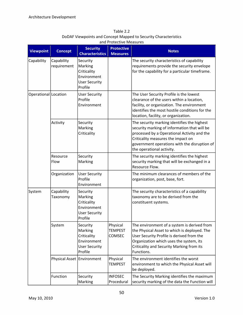
Architecture Development
50 May 10, 2010 Version 1.0
Table 2.2 DoDAF Viewpoints and Concept Mapped to Security Characteristics
and Protective Measures
Viewpoint Concept Security
CharacteristicsProtective Measures
Notes
Capability Capability requirement
Security Marking Criticality Environment User Security Profile
The security characteristics of capability requirements provide the security envelope for the capability for a particular timeframe.
Operational Location User Security Profile Environment
The User Security Profile is the lowest clearance of the users within a location, facility, or organization. The environment identifies the most hostile conditions for the location, facility, or organization.
Activity Security Marking Criticality
The security marking identifies the highest security marking of information that will be processed by a Operational Activity and the Criticality measures the impact on government operations with the disruption of the operational activity.
Resource Flow
Security Marking
The security marking identifies the highest security marking that will be exchanged in a Resource Flow.
Organization User Security Profile Environment
The minimum clearances of members of the organization, post, base, fort.
System Capability Taxonomy
Security Marking Criticality Environment User Security Profile
The security characteristics of a capability taxonomy are to be derived from the constituent systems.
System Security Marking Criticality Environment User Security Profile
Physical TEMPEST COMSEC
The environment of a system is derived from the Physical Asset to which is deployed. The User Security Profile is derived from the Organization which uses the system, its Criticality and Security Marking from its Functions.
Physical Asset Environment Physical TEMPEST
The environment identifies the worst environment to which the Physical Asset will be deployed.
Function Security Marking
INFOSEC Procedural
The Security Marking identifies the maximum security marking of the data the Function will

Architecture Development
51 May 10, 2010 Version 1.0
Viewpoint Concept Security
CharacteristicsProtective Measures
Notes
Criticality process and the criticality represents the degree of harm to government operations if disrupted.
Resource Flow
Security Marking
COMSEC The Security Marking represents the maximum security marking of the Resource Flow.
Performer and Activity
User Security Profile
Procedural The User Security Profile is the lowest clearance of the user performing the function. This should be derived from Organizations who perform the Function, if the information exists.
Service Capability Taxonomy
Security Marking Criticality Environment User Security Profile
The security characteristics of a capability taxonomy are to be derived from the constituent services.
Service Security Marking Criticality Environment User Security Profile
Physical TEMPEST COMSEC
The environment of a service is derived from the Physical Asset to which is deployed. The User Security Profile is derived from the Organization which uses the service, its Criticality and Security Marking from its Functions.
Physical Asset Environment Physical TEMPEST
The environment identifies the worst environment to which the Physical Asset will be deployed.
Activity Security Marking Criticality
INFOSEC Procedural
The Security Marking identifies the maximum security marking of the data the Function will process and the criticality represents the degree of harm to government operations if disrupted.
Resource Flow
Security Marking
COMSEC The Security Marking represents the maximum security marking of the Resource Flow.
Performer and Activity
User Security Profile
Procedural The User Security Profile is the lowest clearance of the user performing the function. This should be derived from Organizations who perform the Function, if the information exists.
Standards Performer Security Marking
INFOSEC Procedural
The Security Marking identifies the security standard for the data the Function will process and the criticality represents the
Architecture Development
52 May 10, 2010 Version 1.0
Viewpoint Concept Security
CharacteristicsProtective Measures
Notes
degree of harm to government operations if there is unauthorized access.