module 7 radio transmission technology finalcemca.org.in/ckfinder/userfiles/files/module...
TRANSCRIPT


Module: 1
Community Radio: An Introduction
Commonwealth Educational Media
Centre for Asia
4
1Commonwealth Educational Media
Centre for Asia
Module: 7
Radio Transmission Technology Course - lll
Community Radio Transmission: System & Technology
Module: 7
Radio Transmission
Technology
Commonwealth Educational Media Centre for Asia
New Delhi
Broadcast Engineering Consultants India Ltd.
Noida, UP
Module: 7
Radio Transmission Technology
Commonwealth Educational Media
Centre for Asia
2
Curriculum Design Experts
Abhay Gupta, BECIL, Noida
Aditeshwar Seth, Gram Vaani, New Delhi
C.R.K. Murthy, STRIDE, IGNOU, New Delhi
D. Rukmini Vemraju, CEMCA, New Delhi
Hemant Babu, Nomad, Mumbai
Iskra Panevska, UNESCO, New Delhi
J. P. Nathani, BECIL, Noida
Jayalakshmi Chittoor, Independent Consultant, New Delhi
K. Subramanian, BECIL, Noida
Kandarpa Das, Radio Luit, Gauhati University, Guwahati
N.Ramakrishnan, Ideosync Media Combine, Faridabad
Pankaj Athawale, MUST Radio; Mumbai University, Mumbai
Ramnath Bhat, Maraa, Bengaluru
Ravina Aggarwal, Ford Foundation, New Delhi
Sanjaya Mishra, CEMCA, New Delhi
Santosh Panda, STRIDE, IGNOU, New Delhi
Satish Nagaraji, One World South Asia, New Delhi
Supriya Sahu, Ministry of I & B, GoI, New Delhi
V. Krishnamoorthy, Independent Consultant, New Delhi
Y. K. Sharma, BECIL, Noida
Instructional Designer
Prof. Santosh Panda
Indira Gandhi National Open
University, New Delhi
Module Editor
Y. K. Sharma
BECIL, Noida
Authors
H. R. Chug (Units 23 & 25)
BECIL, Surat
Hemant Babu (Unit 24)
Nomad, Mumbai
Padarabinda Das (Unit 26)
BECIL, SuratAnkuran Dutta
CEMCA, New Delhi
D Rukmini Vemraju
CEMCA, New Delhi (up to 30.9.2013)
Language Editor
Anamika Ray
Module 7: Radio Transmission Technology
The Commonwealth Educational Media Centre for Asia (CEMCA) is an international organization established by the Commonwealth of
Learning (COL), Vancouver, Canada, to promote the meaningful, relevant and appropriate use of ICTs to serve the educational and training
needs of Commonwealth member states of Asia. CEMCA receives diplomatic privileges and immunities in India under section 3 of the United
Nations (privileges and immunities) Act, 1947.
Broadcast Engineering Consultants India Limited (BECIL) an ISO certified, Mini Ratna public sector enterprise of Government of India was
established in the year 1995 and provides project consultancy services and turnkey solutions encompassing the entire gamut of radio and
television broadcast engineering viz content production facilities, terrestrial, satellite and cable broadcasting in India & abroad. It also
provides associated services like trained manpower and organizing training for the technical staff in the areas of broadcast engineering.
Copyright © CEMCA, 2014.
This module is made available under a Creative Commons Attribution-ShareAlike 4.0 License (international):
http://creativecommons.org/licenses/by-sa/4.0/
For the avoidance of doubt, by applying this license Commonwealth of Learning and Commonwealth Educational Media Centre for Asia (CEMCA)
do not waive any privileges or immunities from claims that they may be entitled to assert, nor do COL/CEMCA submit themselves to the
jurisdiction, courts, legal processes or laws of any jurisdiction.
ISBN:
81-88770-17-5 (10 digits)
978-81-88770-17-5 (13 digits)
While all efforts have been made by Editors to check accuracy of the content, the representation of facts, principles, descriptions and methods
are that of the respective authors. Views expressed in the publication are that of the authors, and do not necessarily reflect the views of
CEMCA/COL. All products and services mentioned are owned by their respective copyrights holders, and mere presentation in the publication
does not mean endorsement by CEMCA/COL. Every effort has been made to acknowledge and attribute all sources of information used in
preparation of this learning material. Readers are requested to kindly notify missing attribution, if any.
For further information, contact:
Commonwealth Educational Media Centre for Asia
13/14, Sarv Priya Vihar
New Delhi - 110016
http://www.cemca.org.in
e-mail: [email protected]
Printed and published on behalf of Director, CEMCA by Mr. R. Thyagarajan, Head (Administration and Finance), CEMCA, 13/14 Sarv Priya Vihar,
New Delhi - 110016, India.
Module Development Team
Layout Designer
Sabyasachi Panja
Chief Editor
B.P. SrivastavaBECIL, Noida
Course Development Coordinators

3Commonwealth Educational Media
Centre for Asia
Module: 7
Radio Transmission Technology
Courses Modules Units
Course I: Module 1 Unit 1 : Community Radio: Concept and
Understanding Community Radio: Evolution
Community Radio An Introduction Unit 2: Context, Access and Equity
(3 Credits, 90 Hours) Unit 3: Community Radio: Policy Guidelines
Unit 4: Technology for CR: Guiding Principles
Module 2 Unit 5: Components of CR Station
Setting up of CRS Unit 6: Radio Waves and Spectrum
Unit 7: Basics of Electricity
Unit 8: Power Backup and Voltage
Stabilization
Course II: Module 3 Unit 9: Basics of Sound
Community Radio Studio Technology Unit 10: Analog and Digital Audio
Production: System & Unit 11: Components of the Audio Chain
Technology Unit 12: Studio Acoustics
(5 Credits,150 Hours)
Module 4 Unit 13: Audio Hardware and Field Recording
Audio Production Unit 14: Free and Open Source Software
Unit 15: Telephony for Radio
Module 5 Unit 16: Sound Recording and Editing
Audio Post Production Unit 17: Mixing and Mastering
Unit 18: File Formats and Compression
Unit 19: Storing and Retrieval
Module 6 Unit 20: Good Engineering Practices for Studio
Studio Operations Setup
Unit 21: Studio Equipment: Preventive &
Corrective Maintenance
Unit 22: Content Distribution: Alternative
Mechanisms
Course III: Module 7 Unit 23: Components of Transmission Chain
Community Radio Radio Transmission Unit 24: Components of FM Transmitter
Transmission: System & Technology Unit 25: Antenna and Coaxial Cable
Technology Unit 26: Propagation and Coverage
(2 Credits, 60 Hrs)
Module 8 Unit 27: Transmitter Setup: Step-by-step
FM Transmitter Setup Unit 28: Transmission System-Preventive and
Corrective Maintenance
Unit 29: Transmission Setup–Good Engineering
Practices
Course IV: Module 9 Section A: Introduction
Technical Internship Practical Internship Section B: Activities to be Conducted During the
(2 Credits, 60 Hrs) Handbook Practical Internship
Section C: The Internship Journal and Self-
Assessment Paper
Section D: Assessment of Internship
Section E: Appendices
Certificate in Community Radio Technology

Module: 7
Radio Transmission Technology
Commonwealth Educational Media
Centre for Asia
4
Video in the Module:
http://tinyurl.com/q2n6wm5
Coaxial Cable and FM
Antenna
By Ramnath Bhat

5Commonwealth Educational Media
Centre for Asia
Module: 7
Radio Transmission Technology
CONTENTSPage No.
About the Module 7
Unit 23 : Components of Transmission Chain 8
23.1 Introduction
23.2 Learning Outcomes
23.3 Transmission Chain Overview
23.4 Live Transmission (Live Console)
23.5 Pre-recorded Transmission (Radio Automation/Scheduling)
23.6 Connectivity (from Studio to Transmitter)
23.7 Audio Processor/Limiter (if not Processed through the PC)
23.8 FM Transmitter
23.9 Principles of FM Transmission
23.10 Antenna (Types and Polarization)
23.11 Let Us Sum Up
23.12 Model Answers to Activities
Unit 24: Components of FM Transmitter 29
24.1 Introduction
24.2 Learning Outcomes
24.3 FM Transmitter Overview
24.4 Power Supply
24.5 Audio Processing
24.6 Exciter
24.7 Amplifier
24.8 Transmitter Maintenance and Fault Diagnosis
24.9 Let Us Sum Up
24.10 Model Answers to Activities
24.11 Additional Readings
Unit 25: Antenna and Coaxial Cable 44
C25.1 Introduction
25.2 Learning Outcomes
25.3 Dummy Load
25.4 Coaxial Cables and Connectors
25.5 Antenna System
25.6 Types of Mast/Tower
25.7 Lightning Arrestor
25.8 Grounding
25.9 Let Us Sum Up
25.10 Model Answers to Activities
Unit 26: Propagation and Coverage 68
26.1 Introduction
26.2 Learning Outcomes
26.3 What is Spectrum?
26.4 Layers of Atmosphere and Radio Wave Propagation
26.5 Factors Affecting Coverage and Shadow Areas
26.6 Topography
26.7 Signal Requirements and Coverage Planning Parameters
26.8 Field Strength Measurements and Drawing an Actual Coverage Map
26.9 Let Us Sum Up
26.10 Model Answers to Activities
26.11 Additional Readings
CO
NT
EN
TS

Module: 7
Radio Transmission Technology
Commonwealth Educational Media
Centre for Asia
6

7Commonwealth Educational Media
Centre for Asia
Module: 7
Radio Transmission Technology
About the Module
Module Description
The first module of Course III: CR Transmission: System & Technology deals with
the transmission technology used in the broadcast of community radio (CR)
programmes/signals generated at the studio of the CR station. In Courses I and II,
you studied about basic CR and studio production of CR programmes. In this unit,
you will learn how these programmes are broadcast by a frequency modulation
(FM) transmitter using radio frequency (RF) signals in FM-band for reception by
FM radio receivers. The first module of Course III is on Radio Transmission
Technology, which has four units. These four units cover the basic components of
the transmission chain and their features and applications (Unit 23), important
components of the FM transmitter (Unit 24) and FM antenna (Unit 25) as well as
the propagation and coverage of FM radio frequency signals (Unit 26). This
module would need about 26 hrs of study. As a part of this module, a video of
antenna installation aspects is also included. After getting a good idea of FM
transmission technology through this module, you will further study the practical
aspects of transmitter set-up in the next module, that is, Module 8. A good
understanding of the basic concepts of this module will help you learn and grasp
better the practical aspects of transmitter set-up.
Module Objectives
After going through this module, you should be able to:
• Enumerate various components of the FM transmission chain and its
features and applications.
• Explain various components of a typical FM transmitter as used for CRS-
FM transmission.
• Describe different types of FM antenna particularly those used for CRS
transmitters, their features and the coaxial cable used to connect with
the transmitter.
• Explain propagation and coverage of RF signals in special reference to
FM propagation.
Units in the Module
• Unit 23: Components of Transmission Chain
• Unit 24: Components of FM Transmitter
• Unit 25: Antenna and Coaxial Cable
• Unit 26: Propagation and Coverage
Module: 7
Radio Transmission Technology
Commonwealth Educational Media
Centre for Asia
8
Components of Transmission
Chain
UNIT 23
Structure
23.1 Introduction
23.2 Learning Outcomes
23.3 Transmission Chain Overview
23.4 Live Transmission (Live Console)
23.5 Pre-recorded Transmission (Radio Automation/Scheduling)
23.6 Connectivity (from Studio to Transmitter)
23.7 Audio Processor/Limiter (if not Processed through the PC)
23.8 FM Transmitter
23.9 Principles of FM Transmission
23.10 Antenna (Types and Polarization)
23.11 Let Us Sum Up
23.12 Model Answers to Activities
9Commonwealth Educational Media
Centre for Asia
Module: 7
Radio Transmission Technology
23.1 Introduction
In Units 5, 11 and 13, you learnt about the functions and use of audio mixers and
audio work stations as a part of studio chain. In this unit, you will learn about
various components of the transmission chain and the functions performed by
each of these. The components of a transmission chain, which will be described
in this unit, include the following:
• Transmission chain overview
• Live transmission (live console)
• Pre-recorded transmission (radio automation/scheduling)
• Connectivity (from studio to transmitter)
• Audio processor/limiter
• FM transmitter
• Principles of FM transmission
• Antenna (types and polarization)
We shall discuss the above components in the order as given.
You will learn in detail about FM transmitter and antenna in the next two units.
You may require about 6 hours to complete this unit including answering
questions in various activities.
23.2 Learning Outcomes
After going through this unit, you will be able to:
• list and describe various components of a transmission chain such as
mixer, workstation, processor, transmitter and antenna.
• describe their features and application in respect of CR stations.
• describe the requirements of connectivity between a studio and the
transmitter.
• explain the necessity of using an audio processor in the transmission
chain.
• explain the basic terms and concepts used in FM transmissions.
• explain different types of antennae and polarizations.
Module: 7
Radio Transmission Technology
Commonwealth Educational Media
Centre for Asia
10
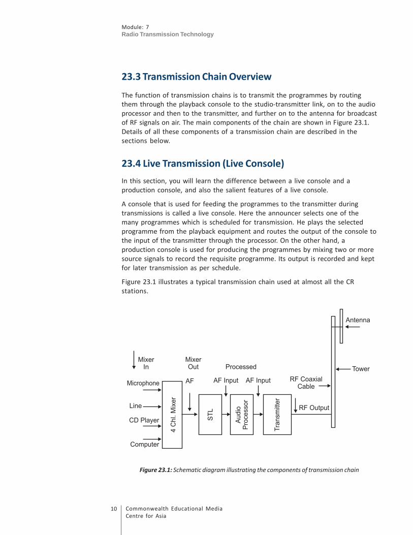
23.3 Transmission Chain Overview
The function of transmission chains is to transmit the programmes by routing
them through the playback console to the studio-transmitter link, on to the audio
processor and then to the transmitter, and further on to the antenna for broadcast
of RF signals on air. The main components of the chain are shown in Figure 23.1.
Details of all these components of a transmission chain are described in the
sections below.
23.4 Live Transmission (Live Console)
In this section, you will learn the difference between a live console and a
production console, and also the salient features of a live console.
A console that is used for feeding the programmes to the transmitter during
transmissions is called a live console. Here the announcer selects one of the
many programmes which is scheduled for transmission. He plays the selected
programme from the playback equipment and routes the output of the console to
the input of the transmitter through the processor. On the other hand, a
production console is used for producing the programmes by mixing two or more
source signals to record the requisite programme. Its output is recorded and kept
for later transmission as per schedule.
Figure 23.1 illustrates a typical transmission chain used at almost all the CR
stations.
Figure 23.1: Schematic diagram illustrating the components of transmission chain

11Commonwealth Educational Media
Centre for Asia
Module: 7
Radio Transmission Technology
You may note the sequence in which the components of the transmission chain
are connected in Figure 23.1. Each stage and the type of signal available at the
input and output of that stage are labelled for the purpose of understanding the
process. The audio mixer/console selects one out of the four input channels that
is to be broadcast. A studio transmitter link (STL) feeds the selected channel to
the audio processor. An STL is, however, not required where the studio and the
transmitter are co-located, which is generally the case with most CR stations. The
audio processor processes the audio signals to increase the average modulation
and at the same time limits the audio level to protect the transmitter from over-
modulation. The output of this processor is fed to the input of the transmitter.
The transmitter then converts the processed audio signals into frequency
modulated (FM) radio frequency (RF) signals at the rated output power. The
output of the transmitter is connected to the antenna system mounted on top of
the tower via an RF coaxial cable. An antenna system converts the RF out of the
transmitter to electromagnetic (EM) waves travelling in all directions.
All the components of the transmission chain will be discussed in detail in this
section as also subsequent sections.
Let us now begin with the first component of the chain, that is, audio mixer/
console, which is used as a live or transmission console. You have already studied
about audio mixer/console in the unit on studio chain. We will here recapitulate
these concepts to refresh your memory.
An audio mixer/console used in broadcast or transmission studio is an electronic
device which is used to select and route one out of a number of playback
equipment connected to it as input channels. The input playback equipment can
be anything from the list below:
• A microphone
• A CD player
• A playback deck
• A line feed having a live programme
• A computer or a workstation
All these pieces of equipment, called the input channels, are connected to the
audio mixer. An Audio Mixer is identified according to the number of input
channels. For example, a 4-channel mixer will have facility to connect four
channels as input channels and any one of them can be selected as output for
feeding it to the next stage. These channels can be mono or stereo, digital or
analog as per requirement.
Audio mixers/consoles of various models and ranges are available in the market.
Prominent manufactures being Behringer, Soundcraft, Studer, Yamaha, Sonifex,
etc. Cost may vary depending on the number of input and output channels, mono
Module: 7
Radio Transmission Technology
Commonwealth Educational Media
Centre for Asia
12
or stereo, analog or digital and additional features/facilities provided by the
manufacturers. Since the CR stations have low budgets, simple 4/6 channel
consoles are mostly used depending upon their specific requirements. Whatever
may be the type/model or brand used, the principle of operation remains the
same.
A typical analog mixer has three main sections, as follows.
1. Channel Inputs
All the input channels are terminated on the mixer generally through good
quality audio cables by using XLR connectors. Each channel has its own switch and
a fader or a knob to control its volume level. The selected channel is connected to
the input bus. Some channels (like microphones) are connected to the input bus
via pre-amplifiers to boost their levels.
2. Master Output
The selected channel is connected to another set of switch, fader and amplifier,
called the master output channel, which feeds the selected programme to the
next stage in the transmission chain after adjusting its output to a desired level.
All other input channels remain isolated by keeping the switches/faders in the
‘Off’ position.
3. Audio Level Metering and Monitoring Facility
Audio level metering facilities are provided to monitor and control the output
level to its nominal level. Usually, there are one or more volume units (VU) or
peak meters to indicate the levels of each channel and the master output.
Generally, a split of input or output signal is extended on a separate jack/
connector (called Aux. Out) to facilitate connecting of auxiliary equipment for
monitoring and measurement.
Apart from the essential components discussed above, the number of additional
features is also provided in these consoles, such as
• Audio oscillator for calibration and level adjustments
• Phantom supplies for microphones
• Equalizers for correcting the frequency response
• Colour coding for quick identification of the operator
In order to maintain proper transmission standards, the output level and
impedance of each equipment must match with the input level and impedance of
the next stage. For example, the nominal level set at the output of audio console
is 0VU (+4dBu). Audio levels in consoles are displayed in VU (see Box 1) or in
decibels (see Box 2).
13Commonwealth Educational Media
Centre for Asia
Module: 7
Radio Transmission Technology
Note It
Box 1
VU meter
A volume unit (VU) meter is a device used for displaying the signal level in
audio equipment.
The VU meter normally measures the average level of the signal. It averages
the peaks and troughs of short durations and thus reflects the perceived
loudness of the signal.
A value of 0VU corresponds to a voltage level of 1.23 Volts (RMS) of an
alternating frequency of 1,000Hz measured across 600 ohm load. This is equal
to +4 dBu (on a decibel scale with reference to 0.775V).
Note It
Box 2
Decibel (dB)
The decibel is a logarithmic unit that indicates the ratio of a physical quantity
(usually power, voltage level of any signal) relative to a specified reference
level. In electronics, the gains of amplifiers, attenuation of signals, and signal
to noise ratios are often expressed in decibels.
A decibel symbol is often qualified with a suffix that indicates which reference
quantity has been used.
For example, dBm indicates a reference level of one milliwatt, while dBu is
referred to 0.775 volts RMS.
Mathematically,
Power gain in dB = 10 log10
(P1 / P
0), where P
1 is the power level to be
measured and P0 is the reference power.
Voltage gain in dB = 20 log10
(V1 / V
0), where V
1 is the voltage level to be
measured and V0
is the reference voltage.

Module: 7
Radio Transmission Technology
Commonwealth Educational Media
Centre for Asia
14
Activity 23.1
To complete this activity, you may need about 15 minutes including writing
down the answers in the space provided.
This activity will help you understand the concepts and functions of the
components of a transmission chain in a CR station. This will also help you in
understanding the representation of audio levels in volume units and decibel
units.
Question: 1 How is a live console functionally different from a production
console?
Question: 2 A VU (volume unit) question meter connected at the output of an
audio mixer displays a level of ‘0’ VU on its scale. What does ‘0’ VU correspond
to?
Question: 3 What is the decibel (dB) unit used for audio levels? Why is a
decibel symbol often written with a suffix? What is the difference between
dBm
and dBu?
23.5 Pre-recorded Transmission (Radio Automation/
Scheduling)
In this section, you will learn about pre-recorded transmissions, radio automation
and scheduling.
In CRS set-ups, most of the programmes are pre-recorded either in the studio or
in the field. They are played from the playback or transmission studios.
Nowadays, a large variety of digital audio workstations (DAW) using radio
automation software are available in the market but the one that best meets the
requirements is used by a particular CR station. You learnt about the details of
audio workstation in Unit 13 including its recording, editing and other features. In
this section, you will learn about the functional requirements as far as scheduling
and automatic transmission of pre-recorded programmes are concerned.
An audio workstation is a computer-based system which is solely designed to
work as an all-in-one machine. It is able to record, edit, store, retrieve and play
back as desired. With the help of a customized radio automation package, the
operator can schedule the transmission for a day on real-time basis. It can
automatically transmit the scheduled programmes on air.
15Commonwealth Educational Media
Centre for Asia
Module: 7
Radio Transmission Technology
Some of the features mostly available in almost all the software are:
• Semantically searchable records from library
• Retrieval of records from the stored data
• Preview of selected programme(s)
• Scheduling (auto transmission on real-time basis)
• Automatic fault diagnosis
• Logging and certification of all audio/data
• Master fader for control of transmission levels
As you learnt in the previous section of this unit, the most important parameter is
to control the output levels of the selected programme (which may be either
from the workstation or any other playback channel selected by the operator) to
ensure that we do not overload the chain beyond the specified levels.
Activity 23.2
To complete this activity, you may need about 15 minutes including writing
down the answer in about 100 words in the space provided.
This activity will help you in understanding the concept and function of digital
workstations.
Question: What is an audio workstation? Why is it becoming more popular to
use it in CRS? Briefly describe its main functions.
Let us now move to the second component of the chain, that is, connectivity
from the studio to the transmitter.
23.6 Connectivity (from Studio to Transmitter)
Your next step is to feed the output of the transmission studio to the transmitter,
which may or may not be located in the same room. For this purpose, a suitable
connectivity is required between the studio and the transmitter. In this section,
you will learn about the various modes of connectivity used from the studio to
the transmitter.
In most CR stations, studio and transmitter are co-located, may be in the same
room or adjoining rooms. But in some of the situations, it is not possible to locate
the transmitter with antenna and tower at a place where the studio is located. In
such situations, it becomes necessary to provide a suitable connectivity between
them.

Module: 7
Radio Transmission Technology
Commonwealth Educational Media
Centre for Asia
16
The various modes of connectivity are as follows:
1. Dedicated Physical Cable Pairs
In most of the CR stations, the distance between the studio and the
transmitter may not be so much that it requires hiring telephone or
leased lines. The transmitter may be located in the same campus but at a
small distance from the studio. In such cases, a good quality shielded
audio cable is laid locally to provide the connectivity. The cable must be
passed through suitable conduits or pipes to avoid getting damaged.
2. Telephone Lines or Leased Lines
The Department of Telecommunication is having a large network of
telephone cables or lines laid in all the cities for providing telephone
connections to the subscribers. This department provides and extends
any number of pairs between two locations (studio and transmitter in our
case) on demand. These are the easiest and cheapest modes of
connectivity. However, the technical quality of this pair may or may not be
up to the mark. It has limited bandwidth. Moreover, if the distance is
more between the studio and the transmitter, the loss due to use of cable
is huge. Nowadays, good quality broadband ISDN or leased lines are also
available but they are costlier.
3. VHF or Microwave Links
The connectivity between the studio and the transmitter can also be
provided by use of point-to-point VHF or microwave links if the distance
is more. Technically, the quality through this link is much better, but it has
got a lot of limitations and restrictions. Separate siting and frequency
clearances from Wireless Planning and Coordination (WPC) are necessary
like a CRS. It involves extra spectrum fees apart from cost of towers and
link equipment. The option is simply not cost effective for a low-budget
CR station.
Laying of dedicated physical pairs for providing connectivity from the studio to
the transmitter is the best possible option. The losses due to length of the
cable can easily be compensated at the input transmitter.
23.7 Audio Processor/Limiter (if not Processed through
the PC)
In Unit 17, you learnt about adjusting and balancing of levels at the mixer output.
In this section, you will learn why it is necessary to process these audio signals
again before feeding them to the transmitter.
Normally, the audio signals received from the broadcast studio are already
processed and level controlled through the transmission console. However, since
17Commonwealth Educational Media
Centre for Asia
Module: 7
Radio Transmission Technology
live consoles use different types of live or pre-recorded programmes, the
recording levels may not be uniform.
An audio processor/limiter is needed to:
• Protect the transmitter against over modulation
• Increase average modulation or loudness
A large variety of audio processors are available in the market with varying range
of features. The prominent ones are Orban, Alto pro, Behringer and Veronica.
Whatever may be the type and brand of processor, the basic functions remain the
same.
Every audio processor has the following three components:
• The compressor
• The limiter
• The peak clipper
The compressor is used to compress the large dynamic range of signals in a
programme. It increases the average modulation level and thereby loudness in
the programme.
The limiter limits the peaks in programmes beyond a set level to protect the
transmitter from over-modulation.
The peak clipper cuts very high peaks, which are otherwise beyond the limiting
level.
Various controls are provided in every processor to set the compression ratio,
attack time, release time and thresholds of limiting and clipping. These are to be
adjusted in accordance with the procedures given in the operating manual of
each processor. The points to be kept in mind are:
• Nominal input levels of transmitters to get desired deviation.
• Quality of programme may not get deteriorated due to over-setting of
compression and limiting.
You will learn about setting of controls and alignment of a transmission chain in
practical workshop.
23.8 FM Transmitter
The next component of the tranmitter chain is the main FM transmitter, which is
used to generate the frequency modulated RF signal of required power for
feeding the transmission antenna for broadcast of RF signals. The FM transmitter
Module: 7
Radio Transmission Technology
Commonwealth Educational Media
Centre for Asia
18
is generally a stand-alone unit housed in a rack mountable box. Generally, a
transmitter with 50 or 100 watt of power is used for CRS. The output of the
transmitter is fed to the transmitting antenna mounted on the pole or tower. You
will learn more about FM transmitters in the next unit.
Activity 23.3
To complete this activity, you may need about 15 minutes including writing
down the answers in the space provided.
This activity will help you learn the necessity and functions of connectivity
and audio processor in the transmission chain.
Question: 1 Why is connectivity required from a studio to a transmitter?
Question: 2 What are the essential technical requirements which the
connectivity link must fulfil?
Question: 3 Differentiate briefly between the functions of a compressor and
a limiter in an audio processor.
23.9 Principles of FM Transmission
The next and the most important component in the transmission chain is the FM
transmitter. An FM transmitter converts processed audio signals to frequency
modulated RF signals before feeding them to the antenna system. In Unit 24, you
will learn in detail about the functions and descriptions of each subunit within
the transmitter. In Unit 6, you were introduced to frequency bands used in FM
radio broadcasting. In this section, you will recapitulate/learn various terms used
in understanding the basic principles of FM transmission.
Frequency Modulation
Frequency modulation is a type of modulation in which the frequency of the
carrier wave is changed by the instantaneous amplitude of the modulating signal,
whereas frequency of the modulating signal changes the rate of change of the
carrier wave. In this process, the amplitude of the modulated carrier wave is kept
constant, which is the most important feature of frequency modulation.
Modulating Signal
Audio frequency signal containing the information or content of the programme
(output of mixer), which is to be transmitted, is called modulating signal. This
signal is a complex wave containing frequencies varying from 30 Hz to 15 kHz with

19Commonwealth Educational Media
Centre for Asia
Module: 7
Radio Transmission Technology
varying amplitudes. In case of stereo transmissions, about which you will learn
later in this section, the maximum frequency of the modulating signal can go up
to 53 kHz.
Carrier Wave
It is the radio wave that acts as a carrier to transmit the message/information
contained in the modulating signal to the listeners through the electromagnetic
wave radiated by the antenna. The frequency of the carrier wave is the frequency
that is allotted to a particular radio station in the VHF band (88 to 108 MHz). For
example, if 90.4 MHz is allotted to a particular CR station, then 90.4 MHz is called
the carrier frequency for that station. Each radio station is identified by its
allotted carrier frequency. If frequency of this carrier wave is varied with the
modulating signal, frequency modulated wave is obtained.
Figure 23.2 illustrates the principle of frequency modulation (FM).
Figure 23.2: The principle of frequency modulation
Figure 23.2 shows three types of waves, namely carrier wave, modulating signal
and the frequency modulated output wave. You should note the difference in

Module: 7
Radio Transmission Technology
Commonwealth Educational Media
Centre for Asia
20
wave shapes of the three waves. In all the three waves, the X-axis represents the
time (i.e., number of cycles travelled by a wave in one second) and the Y-axis
represents the amplitude. The first wave on the top is the un-modulated carrier
wave. It represents the frequency of the radio station. Its amplitude and
frequency remain constant. The middle one represents the audio signal, also
known as the modulating signal. It is the signal that changes the frequency of
carrier wave to get the FM wave (bottom wave). An important point to note here
is that as the amplitude of modulating signal increases (during positive half cycle
of modulating signal), the frequency of carrier wave also increases. As the
amplitude of modulating signal decreases (during negative half cycle of
modulating signal), the frequency of carrier wave also decreases. Another point
which you should note here is that the amplitude of the carrier wave remains the
same before and after modulation.
Frequency Deviation
The amplitude of the modulating signal causes the carrier frequency to deviate
(shift) on both sides of its central frequency by a certain amount. This amount of
deviation is measured in kHz. Deviation is proportional to the amplitude of the
modulating voltage. If we increase the amplitude of the modulating signal, the
deviation also increases. In the Indian system of FM broadcasting, the maximum
deviation allowed is +/- 75 kHz, which is treated as equivalent to 100%
modulation in case of amplitude modulated (AM) transmissions.
Example:
If 0.5V level of audio signal deviates the FM carrier frequency by 10 kHz,
then the deviation produced by 2V level of audio signal will be 40 kHz
{(10/0.5)x2 = 40}.
Deviation Ratio
The ratio of maximum deviation from the carrier frequency to the maximum
frequency in the modulating signal is called the deviation ratio.
Deviation ratio = Maximum frequency deviation/Maximum frequency in
the audio signal
A deviation ratio of 5 (75 kHz/15kHz = 5) is the maximum allowed in case
of FM broadcasting.
Modulation Index
The rate at which the carrier frequency shifts from its centre frequency to give a
certain deviation depends on the frequency of modulating signal. The ratio of
frequency deviation to the frequency of modulating signal is called the
modulating index.

21Commonwealth Educational Media
Centre for Asia
Module: 7
Radio Transmission Technology
Modulation index = Frequency deviation in kHz/ Modulating frequency in
kHz.
For example, If 5 kHz audio frequency (1V level) causes a frequency
deviation of 20 kHz, the modulation index will be 4 (20 kHz/5kHz =4).
Note It
Note that the change in modulating frequency (with same amplitude) does
not change the deviation; however, it changes the modulation index.
Bandwidth in FM
In FM broadcasting, bandwidth is the frequency band around carrier frequency
containing sidebands of significant amplitudes. Bandwidth is dependent on the
number of sidebands produced by the modulating signal and varies with
modulation index. It is a complex process. In practice, it is determined by a rule of
thumb called Carson’s Rule.
Carson’s Rule
It states that the bandwidth of modulated FM wave is twice the sum of
deviation and the highest modulating frequency. For example, if the
maximum deviation is 75 kHz and the maximum modulating frequency
present in the modulating AF frequency is 15 kHz, then according to
Carson’s Rule, bandwidth works out to be 180 kHz [2 ( 75 + 15) = 180 kHz].
To prevent adjacent channel interference, a guard band of 20 kHz is provided.
Thus, the maximum permissible bandwidth in FM broadcasting is 200 kHz.
Pre-emphasis
In speech and music, amplitude levels of high frequencies are always much
weaker than those of low frequencies. Therefore, high frequencies with low
amplitude are not able to cause sufficient deviation in FM. This effect causes
reduction of signal to noise ratio at high frequencies.
In order to overcome this problem, high frequencies in the programme content
are boosted by passing them through an RC network having a time constant of 50
or 75 microseconds. In India, pre-emphasis with 50 microsecond time constant
has been adapted.

Module: 7
Radio Transmission Technology
Commonwealth Educational Media
Centre for Asia
22
De-emphasis
A corresponding attenuation to high frequencies is necessary to be given in the
receiver to get back the original level of high frequencies. This process is called
de-emphasis. The time constant of de-emphasis has to be same as that of pre-
emphasis, that is, 50 microseconds. By now, you might have understood why it is
necessary to follow the same standards for a transmitter and a receiver to be
compatible.
Mono/Stereo Transmissions
Most of the programmes broadcast by the CR stations are monophonic. However,
FM transmitters are capable of transmitting stereo programmes. For this, the
transmitter has to be equipped with an inbuilt stereo encoder card to enable L
and R channels of stereo signals to be broadcast on a single channel transmitter.
The encoder combines the three components, namely mono signal (30 Hz to 15
kHz), stereo signal (23 kHz to 53 kHz) and pilot frequency (19 kHz) to give
multiplexed output signal called ‘MPX’ signal. This composite MPX signal is then
used to frequency modulate the carrier to give a frequency deviation of +/- 75
kHz. In order to standardize the transmissions, a pilot tone system is used for
stereophonic transmissions. Here, a pilot frequency (19 kHz) is added (at a low
level of about 10%) along with monophonic and stereophonic signals. This pilot
tone is used by the receivers to detect the stereo broadcast.
Transmission of Radio Data System (RDS)/Subsidiary Channel Authorization
(SCA)
Radio text data (like station code, auto tuning, traffic information) and a
supplementary speech quality channel (like support commentary) can also be
transmitted simultaneously in addition to monophonic and stereophonic
programmes by using subcarriers of 57 kHz and 67 kHz respectively. With the
addition of RDS and SCA signals, the composite multiplexed output signal gets
modified as shown in Figure 23.3.
Figure 23.3: Stereo multiplex baseband with RDS and SCA signals

23Commonwealth Educational Media
Centre for Asia
Module: 7
Radio Transmission Technology
In Figure 23.3, the X-axis represents the frequency and the Y-axis represents the
voltage or the percentage of deviation produced on each wave. Here also, you
should note the relative placements of monophonic, stereophonic, RDS and SCA
channels in the final composite multiplexed (MPX) output, called baseband
signal. As can be seen in Figure 23.3, the monophonic transmission occupies the
frequency band from 30 Hz to 15 kHz, whereas stereophonic transmission
occupies a frequency band from 23 kHz to 53 kHz. Additional information to be
broadcast using RDS and SCA is placed at 57 kHz and 67 kHz, respectively. The
composite MPX output level is maintained in such a way that the maximum
deviation due to this signal does not exceed +/- 75 kHz. Because of this feature of
placement of frequencies, all these programmes can be simultaneously
transmitted in FM. The listeners can receive any number of the programmes or
data depending upon the availability of receivers/encoders with them.
Transmission Standards
In order to ensure compatibility of the transmitting and the receiving equipment,
it is essential to have well-defined standards. Serious difficulties are felt by
receiver manufacturers if uniform transmission standards are not adopted by the
broadcasters. CCIR recommendation 450-1 defines the transmission standards for
both monophonic and stereophonic transmissions (see Box 3).
Note It
Box 3
Transmission Standards for FM Broadcasting in India
1. Frequency Band = 88–108 MHz
2. Frequency Spacing = 100 kHz
3. Channel Bandwidth = 180 kHz
4. Max Frequency Deviation = +/- 75 kHz
5. Pre-emphasis Characteristics = 50 microseconds
A. Monophonic transmissions
1. Modulating frequency range (AF) = up 15 kHz
B. Stereophonic, RDS and SCA transmissions
1. Pilot tone system using frequency of 19 kHz

Module: 7
Radio Transmission Technology
Commonwealth Educational Media
Centre for Asia
24
2. Sub carrier frequency for stereo = 38 kHz
3. Amplitude modulated with suppressed subcarrier system is used
4. Sidebands = +/–15 kHz of 38 kHz
5. Stereo channel (L – R difference signal)bandwidth = 30 kHz ( 23
kHz–53 kHz)
6. RDS sub carrier = 57 kHz (Deviation +/–2.2 kHz)
7. SCA sub carrier = 67 kHz (Deviation +/–5 kHz)
Activity 23.4
To complete this activity, you may need about 15 minutes including writing
down the answers in the space provided.
This activity will help you in learning and understanding the basic principles of
FM transmission.
Question: 1 What is frequency modulation (FM)? How does it differ from
amplitude modulation (AM)?
Question: 2 What is meant by the term ‘frequency deviation’? How much
change in frequency deviation do you expect if the level of
modulating audio signal is doubled?
Question: 3 Why are transmission standards necessary in FM broadcasting?
23.10 Antenna (Types and Polarization)
In this section, you will learn about the types of antenna and polarization used in
CR stations. While only the functional details will be described in this section,
more details of these components will be given in Unit 25.
The frequency modulated output of the transmitter is fed to the FM antenna via a
low-loss coaxial cable.
Antenna is the final component in the transmission chain which actually converts
the modulated FM carrier into electromagnetic waves.
Types of Antennae and Polarization
Different types of antenna are used in FM broadcasting. Practical antennae are
classified into different types on the basis of their size, shape, method of

25Commonwealth Educational Media
Centre for Asia
Module: 7
Radio Transmission Technology
mounting and the polarization used. The shape can be straight, folded, loop or
helix. The basic type of antenna used is the dipole antenna. When the total
length of two parts of the dipole antenna is equal to a half wavelength, it is called
a half-wave dipole. When a number of radiating elements are mounted one
above the other, it is called an antenna array. This increases the gain of the
antenna. In most CR stations, 2-bay antennae are used.
Polarization is defined as the orientation of electric field component of the
electromagnetic wave with respect to the ground plane. Three types of
polarizations are used in FM broadcasting, namely,
• Horizontal
• Vertical
• Circular
Vertical polarization is most commonly used in CR stations especially because of
its ability of providing higher and better signals in the case of portable radios.
Transmitter output is connected to an antenna through a coaxial cable. You will
learn about the details regarding this in the next unit.
Activity 23.5
To complete this activity, you may need about 10 minutes including writing
down the answers in the space provided. This activity will help you in
understanding the functional characteristics of antenna system.
Question: 1 What is the function of an antenna in a transmission chain?
Which type of antenna is commonly used in CR stations? What
will happen if a 4-bay antenna is used instead of a 2-bay
antenna?
Question: 2 Write down the names of three types of antenna polarizations
used in FM broadcasting. Which type of polarization is preferred
for a CR station?
(i) ……………………………………………………………………………………………….
(ii) ……………………………………………………………………………………………….
(iii)……………………………………………………………………………………………….

Module: 7
Radio Transmission Technology
Commonwealth Educational Media
Centre for Asia
26
23.11 Let Us Sum Up
In this unit on ‘Components of Transmission Chain’, you have learnt that:
• A transmission chain starts with an audio mixer through which the
presenter plays back the selected pre-recorded or live programme and
connects it to the next stage after controlling its levels.
• Pre-recorded transmissions can also be sent to the next stage
automatically as scheduled by the operator by use of audio workstations.
• Physical cable pairs provide connectivity between the studio and the
transmitter.
• In order to maintain proper transmission standards, the output level and
impedance of each equipment must match with the input level and
impedance of the following stage.
• An audio processor is used to process and control the signal levels before
feeding them to the transmitter. Basically, it performs two functions. It
compresses the signal to increase average modulation or loudness and
limits the peaks that exceed beyond safe limit.
• An FM transmitter is a device that converts audio signals to frequency
modulated (FM) radio frequency (RF) signals. The amplifier stages in the
transmitter boost the level of RF signal to the desired output power (e.g.,
50 or 100 Watts).
• Frequency modulation (FM) is the type of modulation through which the
message contained in the audio signals is superimposed on the carrier
wave by changing its frequency. The amount of shift in the carrier wave
(called deviation) is proportional to the amplitude of the audio
frequency. In FM broadcasting, the maximum deviation allowed is +/- 75
kHz.
• In case of stereo transmissions, a pilot tone system is followed in which a
pilot frequency of 19 kHz is transmitted at a low level along with mono
and stereo signals.
• The output of transmitter is fed to an antenna system by the use of a low-
loss coaxial cable. The final component of the chain is the antenna, which
converts the RF power output of the transmitter into electromagnetic
(EM) waves.

27Commonwealth Educational Media
Centre for Asia
Module: 7
Radio Transmission Technology
23.12 Model Answers to Activities
Answers to Questions from Activities 23.1 to 23.5.
Activity 23.1
1 A console, which is used for transmission of different programmes
simultaneously on air, is called a live or transmission console, whereas a
normal production console is used in studios to record a new programme.
2 A VU (volume unit) meter normally measures the average level of audio
signals in volume units. A ‘0’ VU corresponds to a voltage level of 1.23
volts (RMS) of an alternating frequency of 1,000 Hz measured across 600
ohm load. This is equal to + 4 dBu on a decibel scale with reference to 0.775
volts.
3 A decibel (dB) is a logarithmic unit indicating the ratios of the audio levels
relative to specified reference level. A decibel symbol is often written
with a suffix that indicates which quantity has been used as reference. A
dBm
indicates that 1 milliwatt is taken as reference, whereas dBu means
0.775 V (RMS) has been taken as reference.
Activity 23.2
An audio workstation is a computer-based system that is designed to work
as an all-in-one machine. It can be used for recording, editing, storing,
retrieving and playing back any programme at any time. Selecting a
desired programme from a library of stored programmes has become as
fast as a click of a mouse. Because of these features, the use of audio
workstations is becoming more popular in CRS. Apart from the above
mentioned functions, other important features include auto-scheduling,
logging of time/date and programme information, and automatic fault
diagnostics.
Activity 23.3
1 A suitable line or link connectivity is required for feeding the programmes
from the output of transmission studio to the input of the transmitter.
2 Connectivity (line or link) should not offer any attenuation (loss) to the
audio signals. Its frequency response should be flat up to 15 kHz. It should
not have any noise, distortion or break.
3 A compressor circuit compresses the dynamic range of the programme
according to the preset ratio to increase the average modulation level
(loudness). The limiter circuit limits the peaks in the programmes to
protect the transmitter from over-modulation.

Module: 7
Radio Transmission Technology
Commonwealth Educational Media
Centre for Asia
28
Activity 23.4
1 In frequency modulation (FM), the frequency of the carrier wave is
changed in accordance with the instantaneous amplitude of the
modulating signal. In amplitude modulation (AM), the amplitude of the
carrier wave is changed in accordance with the instantaneous amplitude
of the modulating signal.
2 The amplitude of the modulating signal causes the carrier frequency to
deviate (shift) on both sides of its central frequency by certain amount
expressed in kHz. This shift in frequency is called frequency deviation. If
amplitude of the modulating signal is doubled, the deviation produced
will also be doubled.
3 Transmission standards are necessary to ensure compatibility of
transmitting and receiving equipment. For example, a receiver
manufacturer must know the system of modulation used in the
transmitter.
Activity 23.5
1 The function of an antenna is to emit the RF output of the transmitter as
electromagnetic (EM) waves into the air medium. A 2-bay vertically
polarized antenna is commonly used in CRS. By using a 4-bay antenna, the
antenna gain will increase, thereby increasing the coverage.
2 Three types of antenna polarizations used are horizontal, vertical and
circular polarizations. Vertical polarization is commonly used in CRS.

29Commonwealth Educational Media
Centre for Asia
Module: 7
Radio Transmission Technology
Components of FM
Transmitter
UNIT 24
Structure
24.1 Introduction
24.2 Learning Outcomes
24.3 FM Transmitter Overview
24.4 Power Supply
24.4.1 Alternate Current
24.4.2 Switch Mode Power Supply (SMPS)
24.5 Audio Processing
24.5.1 Compressor/Limiter
24.5.2 Stereo Encoder
24.6 Exciter
24.6.1 Phase-locked Loop (PLL)
24.6.2 Audio Modulation
24.6.3 First Stage Amplification
24.7 Amplifier
24.7.1 SMPS
24.7.2 RF Input
24.7.3 Main Pallet (Circuit Board)
24.7.4 Heat Sink
24.7.5 Main Output Transistor
24.7.6 Standing Wave Ratio (SWR) Mismatch and Thermal Protection
24.7.7. Display Panel
24.7.8 Filter
24.7.9 Switchover Panel
24.8 Transmitter Maintenance and Fault Diagnosis
24.9 Let Us Sum Up
24.10 Model Answers to Activities
24.11 Additional Readings

Module: 7
Radio Transmission Technology
Commonwealth Educational Media
Centre for Asia
30
24.1 Introduction
As you know by now, the FM transmitter is one of the most critical components in
the transmission chain. It is a piece of equipment without which a CR station
cannot exist. A technician engaged in running a CR station must understand the
FM transmitter in a greater detail, with its general designing concepts, various
blocks and functions, areas of vulnerability, precautionary maintenance and
troubleshooting. In this unit, you will learn about the various components of an
FM transmitter. Many of these components are essentially used in community
broadcast, while some of the components that you will find here may not be
found in transmitters used in community broadcast systems. However, it is
necessary for you to understand how an FM transmitter in its totality looks like.
After understanding the basic transmitter in this unit, you will learn about
transmitting antenna and propagation in the subsequent units.
Thereafter, you will get an opportunity to have hands-on practical on a
transmitter to get familiarized with practical aspects. You will take about eight
hours to complete this unit.
24.2 Learning Outcomes
After going through this unit, you will be able to:
• identify various parts of an FM transmitter.
• clearly explain its functions and understand its criticality.
• identify faults and suggest remedial measures.
• outline the basic maintenance of a transmitter.
24.3 FM Transmitter Overview
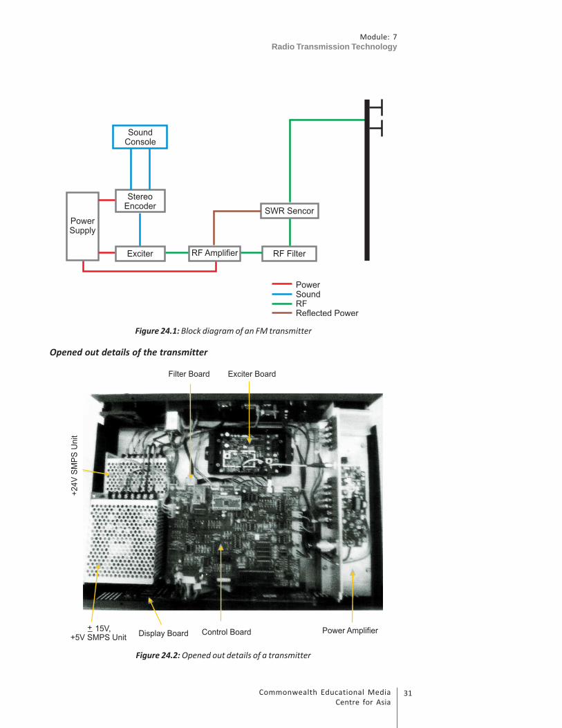
An FM transmitter comprises the following main units:
• Power supply
• Exciter
• Modulator
• Amplifier
• Filter
A block diagram of the transmitter is shown in Figure 24.1.
31Commonwealth Educational Media
Centre for Asia
Module: 7
Radio Transmission Technology
Figure 24.1: Block diagram of an FM transmitter
Opened out details of the transmitter
Figure 24.2: Opened out details of a transmitter
Module: 7
Radio Transmission Technology
Commonwealth Educational Media
Centre for Asia
32
Detailed descriptions of the different units of a transmitter are given in the
sections below.
24.4 Power Supply
It is very important to understand power supply in greater detail for proper
handling of the transmission system. It has been observed that malfunctioning of
power supply is responsible for different troubles that creep into the
transmission system. To understand power supply, you have to first understand
alternate current, its conversion to direct current and supply of different voltages
to the transmission system.
24.4.1 Alternate Current
You have learnt about alternate current in the unit titled ‘Basics of Electricity’.
Alternating current supply, as you may know, approximates 230 V in 50 Hertz cycle
that powers most of the appliances in our homes. When you plug in any home
appliance like TV or washing machine, you don’t know what is really flowing out
of the wall socket as you assume that it would be a supply of 230 V.
However, when you power in a sophisticated and critical component like an FM
transmitter, it is important to know whether what is flowing out of the wall
socket is appropriate for the system.
How to check the wall socket is a subject that you have already learnt in the unit
on Basics of Electricity, but here it is necessary to ascertain whether the quality of
the cable and the plug that supplies 230 V AC power to the transmitter is proper
and supplies consistent power to the transmitter. Generally, the cable is supplied
by the transmitter manufacturer based on the flow of current required by the
transmitter. An engineer’s job is to ascertain that the same and not a similar cable
is used for this purpose. If for some reason the cable is misplaced or has become
faulty, which is highly unlikely, it is necessary to check with the manufacturer the
type of cable that should be used.
In many cases you must have seen that the cable that has a three pin plug on one
end does not fit properly in the socket due to use of a non-standard socket. In
such cases, do not use any temporary measures and arrange for a proper cable.
24.4.2 Switch Mode Power Supply (SMPS)
Since most of the units of the transmitter require DC supply for its operation,
almost all the transmitters convert 230 V AC power to DC power of various
voltages as per the requirement of the transmitter. This function is carried out by
a Switch Mode Power Supply (SMPS). SMPS is used in almost everything in our
day-to-day life. Take any electronic device that is handy to you right now, for

33Commonwealth Educational Media
Centre for Asia
Module: 7
Radio Transmission Technology
example, your mobile phone. The charger of your mobile phone is an SMPS. It
takes 230 V AC from your wall socket and supplies the required DC current to your
mobile battery for charging. Similarly, the charger of a laptop is also an SMPS. If
you open a computer box, you will find an SMPS inside, supplying power to the
various components of the computer like mother board, DVD ROM, or hard disk.
In a normal FM transmitter, there is a requirement of different DC voltages for
different functions. In some transmitters, a single SMPS supplies different
voltages, whereas in some transmitters, different voltages are supplied by
different SMPS.
All SMPS units have both input and output. In most cases, the input would be 230
V AC current, whereas the output will differ based on the design of the
transmitter or a specific function that the SMPS is expected to carry out.
24.5 Audio Processing
24.5.1 Compressor/Limiter
In many transmitters, especially designed for low-powered and low-cost
community radio transmitters, the compressor is found within the transmitter
box. You have learnt about the function of compressors in greater details in Unit
23 titled “Component of Broadcast Chain”. The limiter or compressor that is found
inside the transmitter box or sometimes even part of the exciter has no or very
little manual control. These limiter exciters are optimized at 100 per cent for
broadcast. That means it will give a consistent level of sound without over-
modulating the transmitter.
As you already know, compressor/ limiter is an automatic volume/level control
or, let us say, programmed volume/level control that keeps the audio level at a
consistent loudness. When someone speaks too loud, it will automatically reduce
the volume and when someone speaks too softly, it will automatically increase
the volume.
24.5.2 Stereo Encoder
You have studied about stereo sound in Unit 9 on Basics of Sound. Stereo is a
sound that is divided into left and right channels given to different speakers. Now
you may wonder what if you want to broadcast stereo sound (two L and R
channels) through your transmitter. The problem here is that the transmitter
works only on one frequency and cannot carry two different channels-left and
right-in the stereo.
The solution is that you combine the two channels into one signal and feed it to
the transmitter. This process is called multiplexing/encoding. Any stereo tuner
receiving this signal decodes the multiplex back into separate left and right audio
signals. The stereo coder and the receiver decoder synchronize with each other
Module: 7
Radio Transmission Technology
Commonwealth Educational Media
Centre for Asia
34
using a 19 kHz pilot tone, which is also added to the multiplex signal. Thus, the
decoded signal will play out of a stereo radio in two separate channels-left and
right-with two speakers attached to the radio.
Please note that most transmitters used in CR stations transmit it mono. There
are two reasons for this. The most important reason is that most of the radio
receivers used by the community members are low-cost mono. So, even if a CR
transmits stereo signals, a majority of its listeners are going to listen it in mono.
Second, reception of stereophonic signal requires higher signal. As a result, a
stereo transmitter may have smaller coverage area as compared to a mono
transmitter of the same power.
24.6 Exciter
Exciter is a very important part of the transmission system. The exciter, as its
name suggests, excites the transmission system. In this part, radio signals of low
power are generated, locked to a frequency and then modulated with audio
frequency. This clearly means that there are three processes taking place here
simultaneously. To understand the functioning of an exciter, you need to study
radio signal generation, locking it to a frequency and modulating it to carry the
audio signal.
It would be sufficient here to know that radio signals are generated through
oscillation at a desired frequency. To achieve the desired frequency, all modern
transmitters use a technology called phase-locked loop. This technology is used
to ensure that oscillation does not deviate from the desired frequency.
24.6.1 Phase-locked Loop (PLL)
PLL is the abbreviation of phase-locked loop, a concept that is widely used in any
kind of synchronization process. In a transmitter, it is used to achieve a steady
frequency, say 90.4 MHz, at which a transmitter would radiate.
In the world of electronics, it is quite a complex concept, but for our purpose let
us try and understand with an example. Every household in your neighborhood
will have a wall clock and you must have noticed many of them showing slightly
different time. Now, if these clocks are left to themselves, your neighborhood
will never know what the accurate time is. So, you need to introduce one
reference time, which could be Indian Standard Time (IST). Thus, every time a
clock deviates, the owner of the clock can adjust the time to IST. Now imagine
this process is automatized. Every time a clock deviates from the IST, it corrects
itself. This kind of mechanism can be put in place with PLL.
In the case of CR transmitters, every time a frequency oscillator deviates from a
set frequency–let us say, 90.4 MHz–an electronic circuit brings the oscillation back
to 90.4 MHz. Thus, frequency generation with PLL becomes rock steady.

35Commonwealth Educational Media
Centre for Asia
Module: 7
Radio Transmission Technology
24.6.2 Audio Modulation
Now, your exciter has generated the frequency that needs to be modulated with
sound. Remember the full form of FM-frequency modulation. As you know,
sound broadcasting can be carried by two different modes. One is called
amplitude modulation (AM) and the other is called frequency modulation (FM).
You have already learnt about them in Unit 24. For recapitulation, however, the
wave forms of both these types of modulated signals are reproduced in Figure
24.3.
In an exciter, there is a process of modulating radio frequency with audio signals
in frequency modulation mode. It is here that the signal to noise ratio is
determined and so also the level of modulation. It is also here that where the
modulation level is generally adjusted.
Figure 24.3: AM and FM modulation
24.6.3 First Stage Amplification
The modulated frequency generated with the help of PLL is generally very low in
terms of power. It may be sometimes in a few milliwatts. Before the RF power is
supplied to the amplifier, it needs to be pre-amplified to a level suitable for the
amplifier design. For example, if your amplifier is designed to give 20 dB gain
(You may find this in detail in the technical specification document provided by
your transmitter manufacturer), then 1 W of RF power will be amplified to 100 W.
That makes it necessary for the exciter to generate 1 W, so that an amplifier can
amplify it to 100 W.
Module: 7
Radio Transmission Technology
Commonwealth Educational Media
Centre for Asia
36
Activity 24.1
Answer the following questions:
Question-1: What is the role of a PLL circuit?
Question 2: Draw a diagram showing amplitude modulation and frequency
modulation and briefly explain the difference between the
two.
Question 3: If possible, visit the nearest CR station and check power output
of the exciter. You may refer to the manufacturer’s literature.
Write your observations.
24.7 Amplifier
RF amplification is a complex process. To begin with, it requires a low power radio
signal that will have to pass through the final stage output transistor and
induction coils. Also required is a filter circuit to cut out spurious and harmonics.
Here, we will discuss the important components/process of amplification.
24.7.1 SMPS
As discussed earlier, the amplifier of the transmitter will require DC voltage. The
power unit inside your transmitter box, known as SMPS, would be giving
necessary DC voltage to the amplifier. In any transmitter, this would be the most
critical and vulnerable component. If you find your amplifier not working, the
first thing you need to check if the SMPS output voltage being supplied to the
amplifier.
24.7.2 RF Input
The main function of an amplifier is to take small amount of RF power and
amplify it to the necessary levels. That means there would be an RF power inlet
in the amplifier. Different amplifiers have different input sockets: some use
SO239 or UHF type sockets; some may use N type sockets; and some amplifiers
use BNC types. If your exciter unit and amplifier unit are in the same box, the
connectivity may differ. But remember that RF power is never carried anywhere
without shielded cables. So, from the exciter unit to the amplifier you will see a
coaxial cable, which transports the RF power to the amplifier.
24.7.3 Main Pallet (Circuit Board)
The main pallet is the printed circuit board that handles the entire amplification

37Commonwealth Educational Media
Centre for Asia
Module: 7
Radio Transmission Technology
process. On this board you will find various coils, trimmers, RF chokes and other
electronic components. Unless you are in a position to understand the whole
process in great detail, it is most advisable to refrain from touching this part of
the amplifier in the absence of proper tools and testing equipment.
24.7.4 Heat Sink
Most of the amplifier pallets are mounted on a heat sink, which is made of high
grade aluminium blocks designed in such a way that it has the maximum surface
area in a small form factor to absorb and radiate maximum heat. As the amplifier
will generate radio frequency signals, it will also generate heat in proportion to
the RF power. This heat has to be captured and thrown away from the amplifier
unit. The heat sinks are used to capture all the heat that the amplification process
generates.
The heat sink is supplemented by DC fans. In some transmitters, the fans are used
to bring in cool air from outside in the transmitter box to keep the heat sink
cooler. In some cases, the fans are used for throwing out hot air. But in many
transmitters the fans work in both directions, that is, bring in cool air and throw
out hot air. Fans are the only moving parts in the transmitter and quite likely to
develop snag. These fans have ball bearings that can be damaged by their close
proximity to RF.
24.7.5 Main Output Transistor
This output transistor is the core of your entire transmission system. It is this
electronic part that generates the power output. It is one of the most expensive
and vulnerable parts in the transmitter. It can easily be destroyed and, once
damaged, it cannot be repaired. It is advisable not to touch or fiddle with it during
maintenance
24.7.6 Standing Wave Ratio (SWR) Mismatch and ThermalProtection
Advanced transmitters available in the market have built-in protection for high
SWR and thermal overloads. The function of the SWR protection circuit is to
ensure that the transmitter is protected against very high SWR by switching off
the transmitter (You will learn about it in the unit on Antenna). This circuit will
fold up the power of the transmitter if it detects a very high SWR. The high SWR
could be caused by many conditions such as damage to the antenna, break in the
feeder cable or malfunctioning of connectors. If this condition persists, the
reflected power will damage or sometimes even destroy the main output
transistor.
Similarly, if the cooling mechanism of the transmitter fails, the transmitter will
start getting heated up due to RF power. Thermal overload protection is provided
to take care of this eventuality and shut down the transmitter.
Module: 7
Radio Transmission Technology
Commonwealth Educational Media
Centre for Asia
38
24.7.7. Display Panel
Though it is not absolutely necessary, it is quite useful to have a display panel on
the transmitter. This panel displays operating parameters of a transmitter when
switched on. It could display the following parameters:
• Operating Frequency
• Output Power
• Reflected Power
Audio Levels or Modulation Levels
There are many advanced transmitters that provide the facility of changing
certain parameters like frequency. But all transmitters do not let the user change
the parameters from the control panel.
Please note that parameters shown in the display are for reference only.
Sometimes the actual parameters measured with calibrated test equipment,
which you may otherwise not find in a CR station, could differ from what is
displayed in the built-in display panel.
24.7.8 Filter
Every oscillation process generates spurious signals, which are not intended to be
generated. These signals could be anywhere in the radio frequency spectrum.
They could even be harmonics in the exact multiple of the operating frequency
but in a completely different band of spectrum. The spurious signals do not affect
your transmission as much as it affects other equipment that may be using RF
spectrum. Any transmitter that generates a spurious beyond the prescribed limit
is known as a “dirty transmitter”.
ITU(R) and other national regulatory bodies have specified limits for spurious and
harmonic radiations. It is, therefore, necessary that a transmitter filters out such
radiations. For this purpose, all transmitters have a filter that suppresses the
spurious and harmonious signals. There are different designs of filters but all of
them are located at the last stage before the RF signals go out to the antenna
through the feeder cable.
24.7.9 Switchover Panel
There is a general practice in radio stations to always keep a back-up transmitter.
If one of the transmitters fails, the broadcast could be switched over to the spare
transmitter. A community FM transmitter can use an automatic switchover system
or a manual switchover system for this purpose. In an automatic system, both the
transmitters are kept simultaneously switched on. The power of one transmitter

39Commonwealth Educational Media
Centre for Asia
Module: 7
Radio Transmission Technology
is sent to the antenna system, while the second transmitter power would be sent
to a dummy load that will convert the power into heat and absorb.
In the case of a manual system, you have to physically disconnect the
malfunctioning transmitter from the audio and antenna system and connect the
spare transmitter.
If your station is well-designed and you are well versed with the process of
switching over, it may take less than a minute.
Please remember that automatic switchover panel would consume a bit of power.
In high-powered systems, like that of a commercial radio station, this loss of
power could be considered negligible, but in a CR station where the permitted
power is just 50 W, even a single watt loss is undesirable. For this reason, most CR
stations prefer manual switchover.
24.8 Transmitter Maintenance and Fault Diagnosis
After getting an idea about the components of an FM transmitter and the
functions of its parts, it will be desirable to have an idea about the basic
maintenance of an FM transmitter and fault diagnosis techniques. These are
detailed below:
Note It
Box-1
Transmitter Maintanance and Checkup
A transmitter is very critical and perhaps one of the most expensive pieces of
equipment in a CR station. Experience shows that an FM transmitter can run
flawlessly for years if it is installed properly and maintained with meticulous
regularity. Here are some of the maintenance tasks that should be carried out
on daily, weekly and monthly bases.
Daily Tasks:
1. Ensure that the transmitter area/room is properly cleaned and no dust
is allowed to settle in any corner.
2. Check the power and reflected power on the front panel and make a
note of it in a log book so that if any fault is developing you have a
historic perspective.
Module: 7
Radio Transmission Technology
Commonwealth Educational Media
Centre for Asia
40
3. Check the modulation levels on the front panel and audio quality on a
standard radio receiver. Look out for any hum or unusual sound.
4. Check all the connectors for any visible sign of stress, heat or any
abnormality.
5. Give a visual check of the antenna system and see if there is any
misalignment.
Weekly Tasks:
1. Take a weekly maintenance shutdown if your radio station is running 24
hours.
2. Check the phase, neutral and earthing of your AC power supply. Use
multi meter for the purpose.
3. In monsoon season ensure that humidity level is under control in the
transmitter area
Monthly Task
1. If you have manually switchable 1+1 configuration, then switch the
operational transmitter from A to B or the reverse.
2. De-dust the transmitter with an air blower. Remember to necessarily
open the lead of the transmitter. An electric blower (not the one used
for hair styling) is generally used for cleaning.
Note It
Box 2
Troubleshooting:
If one fine morning, or not so fine morning, you start receiving calls from your
listeners that they cannot hear anything, or you switch on the transmitter and
the power indicator does not show power or shows inadequate power, the first
thing you should do is not to panic. Please follow the diagnosis methodology as
mentioned here.
• First of all, tune your radio to the frequency of your radio station. If you
hear complete silence, it means the transmitter is working fine but the
trouble is with your speech input equipment. Check your mixer or the
source output and also the connectivity between your audio source and
the transmitter.
41Commonwealth Educational Media
Centre for Asia
Module: 7
Radio Transmission Technology
• If your callers say they cannot hear anything, please calm them down and
ask the following questions:
♦ Ascertain if they cannot hear anything or they can hear your station
with a lot of noise.
♦ Ask what kind of radio receiver they are using.
♦ Ask since when they have been facing this trouble.
• Give a quick look at the front panel power meter on your transmitter.
Check the forward and reflected power. You may come across the
following situations:
♦ Power is very less than stipulated 50 W: In this circumstance, first check
the reflected power. If it shows more than 1.8 SWR, you know that the
trouble is with your antenna system. Check all connectivity and the
antenna alignment. In such circumstances, it is advisable to switch off
the transmitter or switch over to a back-up transmitter.
♦ You may see there is no power at all: In this situation, tune in your
radio receiver close to the transmitter, if you cannot hear your station
at all, then the origin of the fault could be at the exciter level. But if
you can hear your station well, it means the amplification process is
notworking due to some fault in the amplifier.
Even if you find the fault, do not carry out any repair before talking to the
supplier of your transmitter. Please call your supplier, explain the problem
and discuss your diagnosis before you carry out any repair.
Activity 24.2
Answer the following questions
Question 1: What is the function of an RF filter?
Question 2: Draw a block diagram of a transmitter describing the generation of
an RF carrier, modulation and process of amplification.
24.9 Let Us Sum Up
Now we know that an FM transmitter is divided mainly in two sections, namely an
exciter and an amplifier. Both the sections could be in one box or separate boxes.
Both the sections will require separate DC power current, which is provided by a
Switch Mode Power Supply (SMPS).

Module: 7
Radio Transmission Technology
Commonwealth Educational Media
Centre for Asia
42
The exciter generates small amount of RF power and supplies it to the amplifier,
which in turn amplifies the power and propagates it through an antenna. This
simple process also involves modulation of frequency with sound and filtration of
spurious and harmonics. All transmitters have front panel display that shows
some of the basic parameters like operating frequency, output power, reflected
power, modulation levels, etc. A good transmitter must have a thermal and SWR
protection.
Remember a transmitter does not require much tweaking once installed
correctly. All that a technician is expected to do is to keep the transmitter in a
clean and dust-free environment and regularly monitor its operations.
24.10 Modal Answers to Activities
Activity 24.1
1. A phase-locked loop (PLL) is a control system that generates output based
on input reference signal. A PLL circuit comprises a variable frequency
oscillator and phase detector. The circuit takes the phase of an output
oscillator and compares its frequency with the phase of the input and its
frequency. On any variation it corrects the frequency of output phase.
In a CR transmitter, the PLL is used at the exciter stage to lock the exciter
frequency to the desired frequency allocated to the radio station by the
government (WPC, DOT).
PLLs are widely used in many types of electronic applications including
radio, telecommunications and computers.

43Commonwealth Educational Media
Centre for Asia
Module: 7
Radio Transmission Technology
2. As can be seen in the diagram, in the case of AM the sound signal affects
the amplitude of the carrier wave, whereas in FM the frequency of the
carrier itself is modulated with the sound wave. The difference is that AM
can travel very long distance but the sound quality is not as good,
whereas in FM, though it travels comparatively shorter distance, it
produces a very good sound quality.
Activity: 24.2
1. As we all know, the oscillation process produces some amount of spurious
and harmonics. Spurious is a frequency not deliberately created but gets
generated in the process of oscillation. Any other signal that a transmitter
generates outside its desired frequency is called harmonics. There are
international standards for spurious and harmonics.
An RF filter is designed to filter out these spurious and harmonics so that
a transmitter does not generate a signal that can interfere with other
devices. In short, it keeps the spectrum clean.
24.11 Additional Readings
• Gibilisco, S. (2002). Teach yourself electricity and electronics. New York:
McGraw Hill.
• Noll, A. Michael. (2001). Principles of modern communications technology.
Artech House.
• HYPERLINK “http://www.itu.int/rec/R-REC-BS.450-3-200111-I/
en”Transmission standards for FM sound broadcasting at VHFHYPERLINK
“http://www.itu.int/rec/R-REC-BS.450-3-200111-I/en”. ITU Rec. BS.450.
International Telecommunications Union.

Module: 7
Radio Transmission Technology
Commonwealth Educational Media
Centre for Asia
44
FM Antenna and Coaxial
Cable
UNIT 25
Structure
25.1 Introduction
25.2 Learning Outcomes
25.3 Dummy Load
25.4 Coaxial Cables and Connectors
25.5 Antenna System
25.5.1 Types of Antennae
25.5.2 Gain of Antenna
25.5.3 Polarization
25.5.4 Radiation Patterns
25.6 Types of Mast/Tower
25.6.1 Location
25.6.2 Tower and Foundation
25.6.3 Mounting of Antenna and Cable on Tower
25.6.4 VSWR
25.7 Lightning Arrestor
25.8 Grounding
25.9 Let Us Sum Up
25.10 Model Answers to Activities
45Commonwealth Educational Media
Centre for Asia
Module: 7
Radio Transmission Technology
25.1 Introduction
In Unit 23, you learnt about the components of a transmission chain. Then in Unit
24, you learnt about the main component of the transmission chain, the FM
transmitter. The output of the transmitter is connected to the antenna for on-air
broadcast of RF signals. You were introduced to the types of antenna and
polarization in Unit 23. In this unit, you will learn about the constructional details,
technical specifications, functions and application aspects of the following
components of the complete antenna system.
• Dummy load
• Coaxial cable
• Antenna system
• Supporting structure of antenna system
• Lightning arrestor
• Grounding system
As a part of this unit, in the video on “Types of Antenna and Installation”, you will
see the different types of antennae and their mounting arrangements on towers/
poles. You will also see how tower foundations, grounding and lightning arrestor
arrangements are provided in a typical CR station.
You will learn about propagation and coverage aspects linked with the different
types of antennae in the next unit, that is Unit 26, on propagation and coverage
aspects.
You may need about 6 hours to complete this unit including answering the
questions given in the activities.
25.2 Learning Outcomes
After reading this unit, you will be able to:
• list and describe the types of dummy load, coaxial cables, FM antennae
and supporting towers used in a typical CR station.
• describe the constructional details of dummy load and its application.
• describe the constructional details of coaxial cables and their
characteristics.
• identify and describe different types of FM antennae.
• define polarization and underline the significance of different types of
polarization.
Module: 7
Radio Transmission Technology
Commonwealth Educational Media
Centre for Asia
46
• differentiate between horizontal and vertical radiation patterns
produced by practical antennae.
• list and describe different types of towers used in CR stations.
• explain the meaning and significance of VSWR.
• justify the necessity of lightning arrestor and grounding system.
We will begin with dummy load.
25.3 Dummy Load
In this section, you will learn about the purpose, constructional details and
working principle of dummy loads provided in CR stations.
Dummy load is a device that is used to test the working of a transmitter before its
output is connected to a cable and an antenna. The difference between a dummy
load and an antenna is that a dummy load converts the RF energy into heat and
not into electromagnetic waves, as is done by an antenna. Dummy loads are
available in different types depending upon their power handling capacities.
Dummy loads used for testing of high-power transmitters require forced air or
water cooling. Since the power of a transmitter to be tested in CR stations is of
the order of only 50 to 100 W, a small dummy load capable of dissipating a power
of 100 W with convection cooling is sufficient.
Figure 25.1 shows the cut-out details of a typical dummy load capable of
dissipating 100 W power, which is commonly used in CR stations.
Figure 25.1: Cut-out details of dummy load

47Commonwealth Educational Media
Centre for Asia
Module: 7
Radio Transmission Technology
As can be seen in Figure 25.1, a dummy load consists of a 50 ohm/100 W non-
inductive carbon resistor mounted on a heat sink having a large surface area and
fins to dissipate the heat. One terminal of the resistor is connected to an ‘N’
(Female) type of connector and the other terminal is connected to the body of
heat sink. When RF power of transmitter is connected to a dummy load via ‘N’
connector, it gets heated like any other heater. The heat produced in the resistor
is dissipated in air by the heat sink. The surface area of heat sink is large enough
to dissipate heat generated in the resistor to the surrounding air without raising
its temperature.
The basic technical specifications/requirements of a dummy load are as follows:
• It should be purely resistive.
• It should not radiate RF energy in the air medium.
• Its power dissipation capacity must not be less than that of transmitter
power.
• Its impedance should remain constant and should not vary with
application of RF power.
• VSWR (Voltage Standing Wave Ratio, which will be explained later) of a
perfectly matched dummy load is unity (1:1) but should not exceed 1.05:1.
Specifications of different models supplied by different firms vary according to
the design of their products but you have to see that the minimum specified
requirements are met while selecting a dummy load.
Activity 25.1
To complete this activity, you may need about 10 minutes including writing
down the answers in the space provided. This activity will help you in
understanding the constructional and functional details of the dummy loads.
Question 1: What is the purpose of providing a dummy load in a CR station?
Question 2: Why are non-inductive resistors used in the construction of a
dummy load?
Question 3: Why are fins and a large surface area provided in a dummy load?
Question 4: What should be the input impedance of a dummy load?
Question 5: Why are water-cooled/oil-cooled dummy loads used with high-
power FM transmitters?
Now let us discuss the next important component of a transmission chain, that is,
a coaxial cable and connectors.
Module: 7
Radio Transmission Technology
Commonwealth Educational Media
Centre for Asia
48
25.4 Coaxial Cables and Connectors
In this section, you will learn about the purpose, constructional details and
characteristics of the types of coaxial cables commonly used in CR stations.
The cables used for connecting the RF output of a transmitter to the antenna
system are called coaxial cables. They come in different sizes and ratings. The size
and type of coaxial cable depends on the power of the transmitter and
attenuation (loss) of cable at the operating frequency. Since CRS set-up consists
of a low power transmitter of the order of 50 W to 100 W, a low-loss cable of ½”
size having foam dielectric is sufficient. Figure 25.2 shows the constructional
details of a typical coaxial cable.
Figure 25.2: Schematic diagram showing construction of coaxial cable
As can be seen in Figure 25.2, a coaxial cable is made of two conductors, called
the inner conductor and the outer conductor. The inner conductor is usually made
of aluminium or copper and the outer conductor is made of corrugated copper
sheet. The inner conductor is held in central position of the outer tubular
conductor throughout the length of the cable by use of a uniform layer of
insulating foam polyethylene dielectric material. A protective layer of PVC jacket
is provided over the outer conductor to avoid any possible damage during
handling and use.
Materials used for making inner and outer conductors may vary from
manufacturer to manufacturer. However, the constructional design remains the
same. Higher sized cables (Cables of size higher than 7/8") are available with air or
foam dielectric which can be procured as desired by the user. Cables with air
dielectric require pressurization to avoid entry moisture in them.
Important terms/specifications commonly used in identification and selection of
coaxial cables are as follows:
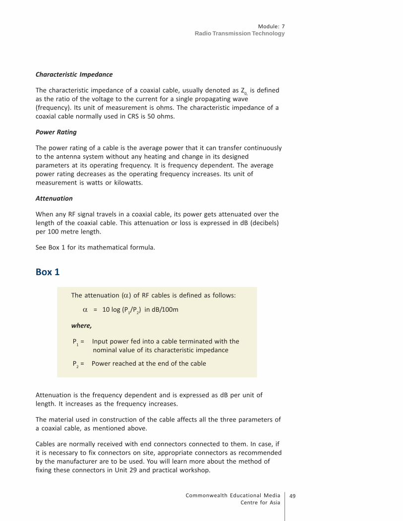
49Commonwealth Educational Media
Centre for Asia
Module: 7
Radio Transmission Technology
Characteristic Impedance
The characteristic impedance of a coaxial cable, usually denoted as Z0, is defined
as the ratio of the voltage to the current for a single propagating wave
(frequency). Its unit of measurement is ohms. The characteristic impedance of a
coaxial cable normally used in CRS is 50 ohms.
Power Rating
The power rating of a cable is the average power that it can transfer continuously
to the antenna system without any heating and change in its designed
parameters at its operating frequency. It is frequency dependent. The average
power rating decreases as the operating frequency increases. Its unit of
measurement is watts or kilowatts.
Attenuation
When any RF signal travels in a coaxial cable, its power gets attenuated over the
length of the coaxial cable. This attenuation or loss is expressed in dB (decibels)
per 100 metre length.
See Box 1 for its mathematical formula.
Box 1
The attenuation (α) of RF cables is defined as follows:
α = 10 log (P1/P
2) in dB/100m
where,
P1 = Input power fed into a cable terminated with the
nominal value of its characteristic impedance
P2 = Power reached at the end of the cable
Attenuation is the frequency dependent and is expressed as dB per unit of
length. It increases as the frequency increases.
The material used in construction of the cable affects all the three parameters of
a coaxial cable, as mentioned above.
Cables are normally received with end connectors connected to them. In case, if
it is necessary to fix connectors on site, appropriate connectors as recommended
by the manufacturer are to be used. You will learn more about the method of
fixing these connectors in Unit 29 and practical workshop.

Module: 7
Radio Transmission Technology
Commonwealth Educational Media
Centre for Asia
50
Activity 25.2
To complete this activity, you may need about 10 minutes including writing
down the answers in the space provided.This activity will help you in
understanding the characteristics of an RF coaxial cable.
Question 1: Why should we use a low-loss cable in a CRS?
Question 2: What type of dielectric material is used between inner and outer
conductors of a typical ½” coaxial used in CRS?
Question 3: What do you mean by the term characteristic impedance of a
coaxial cable?
Question 4: 50 W output of a transmitter is fed to an antenna. Calculate the
attenuation in decibel units if only 25 W reaches the antenna?
Question 5: What is the relation between average power rating and frequency
of operation in an RF coaxial cable?
Now we move to the last and most important component in a transmission chain
in a CR station, that is, its antenna system.
25.5 Antenna System
In previous sections, you learnt about dummy loads and coaxial cables. The RF
output from the transmitter is fed to the antenna system via a coaxial cable. It is
the antenna that converts the RF output of the transmitter into electromagnetic
waves received by listeners through their receivers. It is, therefore, the antenna
that plays a major role in affecting the coverage of the station. In this section and
the subsections that follow, you will learn in detail about the following
characteristics of antennae:
• Types of antennae
• Gain of antennae
• Polarization
• Radiation patterns
Let us begin with the types of antennae commonly used in CR stations.
25.5.1 Types of Antennae
FM antennae come in different sizes and shapes. They are usually classified into
different types according to their size, shape and number of radiating elements,
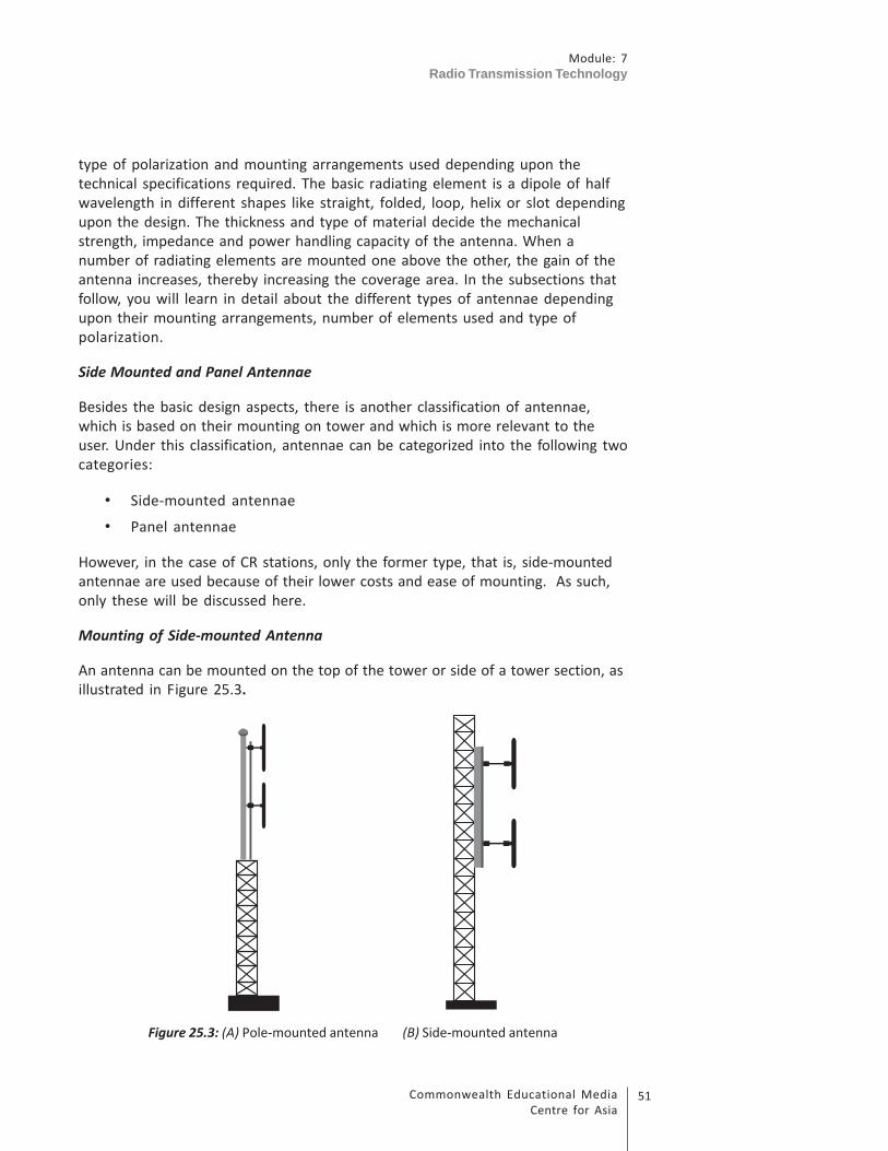
51Commonwealth Educational Media
Centre for Asia
Module: 7
Radio Transmission Technology
type of polarization and mounting arrangements used depending upon the
technical specifications required. The basic radiating element is a dipole of half
wavelength in different shapes like straight, folded, loop, helix or slot depending
upon the design. The thickness and type of material decide the mechanical
strength, impedance and power handling capacity of the antenna. When a
number of radiating elements are mounted one above the other, the gain of the
antenna increases, thereby increasing the coverage area. In the subsections that
follow, you will learn in detail about the different types of antennae depending
upon their mounting arrangements, number of elements used and type of
polarization.
Side Mounted and Panel Antennae
Besides the basic design aspects, there is another classification of antennae,
which is based on their mounting on tower and which is more relevant to the
user. Under this classification, antennae can be categorized into the following two
categories:
• Side-mounted antennae
• Panel antennae
However, in the case of CR stations, only the former type, that is, side-mounted
antennae are used because of their lower costs and ease of mounting. As such,
only these will be discussed here.
Mounting of Side-mounted Antenna
An antenna can be mounted on the top of the tower or side of a tower section, as
illustrated in Figure 25.3.
Figure 25.3: (A) Pole-mounted antenna (B) Side-mounted antenna

Module: 7
Radio Transmission Technology
Commonwealth Educational Media
Centre for Asia
52
Figure 25.3 (A) shows the mounting arrangement of an antenna on the top of the
tower. In this arrangement, two dipoles are mounted on a pole, which is fixed on
the top of the tower. The thickness of the pole is smaller than the size of a cross
section of the tower. In this case, the horizontal radiation pattern is nearly omni-
directional. Figure 25.3 (B) shows an antenna mounted on the side of the tower.
In this case too, the dipoles are mounted on a pole (called supporting structure)
and the pole is clamped to the tower at a suitable distance. Even though the size
of the supporting structure section is chosen to be much less as compared to the
size of the supporting tower, the radiation pattern gets some directivity (pattern
gets elongated due to more signal strength) in a particular direction due to
presence of reflecting surface of the tower section. The type of mounting can be
decided based upon the conditions existing at the site. Irrespective of the
mounting, the most commonly used antenna in CR stations is described below.
Most Commonly Used Antenna in CRS – 2-Bay Vertically Polarized Antenna
Now you will learn more about a typical 2-bay vertically polarized FM antenna,
which is most commonly used in CR stations. Only physical construction and
technical specifications will be described here, whereas radiation, propagation
and coverage aspects will be described in Unit 26.
Figure 25.4: Schematic diagram of 2-bay vertically polarized antenna
Figure 25.4 illustrates a schematic diagram showing two dipoles of half
wavelength each mounted on the pole. The output of the transmitter is
connected to the input of a two way power divider, which gives two outputs
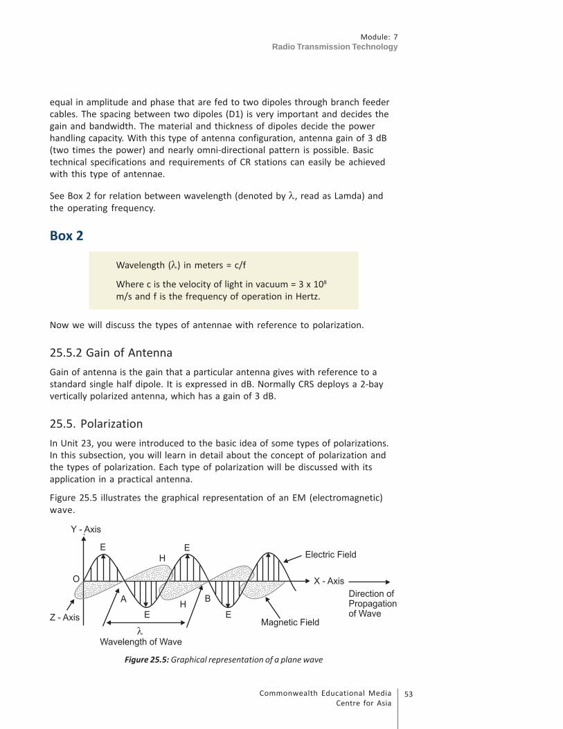
53Commonwealth Educational Media
Centre for Asia
Module: 7
Radio Transmission Technology
equal in amplitude and phase that are fed to two dipoles through branch feeder
cables. The spacing between two dipoles (D1) is very important and decides the
gain and bandwidth. The material and thickness of dipoles decide the power
handling capacity. With this type of antenna configuration, antenna gain of 3 dB
(two times the power) and nearly omni-directional pattern is possible. Basic
technical specifications and requirements of CR stations can easily be achieved
with this type of antennae.
See Box 2 for relation between wavelength (denoted by λ, read as Lamda) and
the operating frequency.
Box 2
Wavelength (λ) in meters = c/f
Where c is the velocity of light in vacuum = 3 x 10⁸
m/s and f is the frequency of operation in Hertz.
Now we will discuss the types of antennae with reference to polarization.
25.5.2 Gain of Antenna
Gain of antenna is the gain that a particular antenna gives with reference to a
standard single half dipole. It is expressed in dB. Normally CRS deploys a 2-bay
vertically polarized antenna, which has a gain of 3 dB.
25.5. Polarization
In Unit 23, you were introduced to the basic idea of some types of polarizations.
In this subsection, you will learn in detail about the concept of polarization and
the types of polarization. Each type of polarization will be discussed with its
application in a practical antenna.
Figure 25.5 illustrates the graphical representation of an EM (electromagnetic)
wave.
.
Figure 25.5: Graphical representation of a plane wave

Module: 7
Radio Transmission Technology
Commonwealth Educational Media
Centre for Asia
54
As can be seen in Figure 25.5, an electromagnetic wave has two components,
electric field E and magnetic field H, which are perpendicular to each other. Both
are also perpendicular to the direction of travel of the wave. The direction of
each component of electromagnetic wave should be noted. In this figure,
direction of travel of wave is along X-axis, direction of E component is along Y-axis
and that of H component is along Z-axis. The plane of electric field E with respect to
the ground is called the plane of polarization. The wave shown in this figure is a
vertically polarized wave.
Types of Polarization
Basically, three types of polarization are used in FM broadcasting:
1. Horizontal polarization
2. Vertical polarization
3. Circular polarization
Horizontal Polarization
When the plane of electric field component E is parallel to the ground, it is called
horizontal polarization.
Figure 25.6: Horizontally polarized antenna
Figure 25.6 shows a horizontally polarized antenna. Note the direction of
mounting of the longer side axis of the antenna. Physically, the radiating dipole
element is mounted parallel to the ground and therefore, the antenna is called
horizontally polarized antenna.
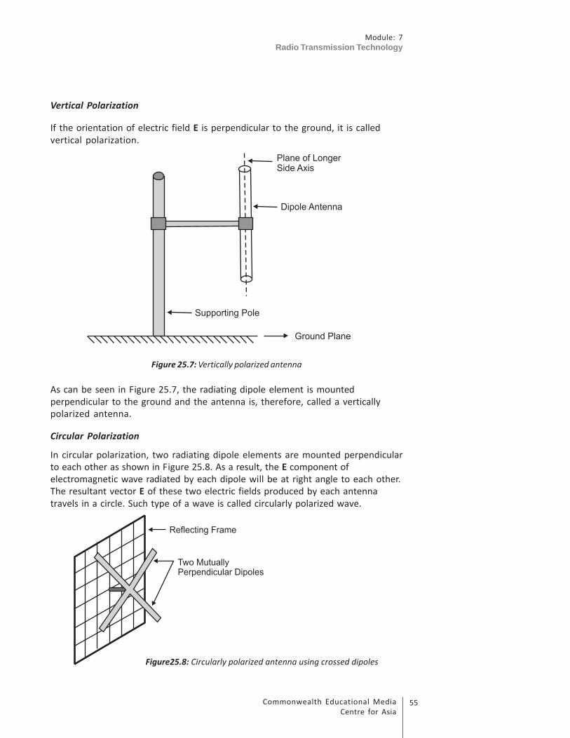
55Commonwealth Educational Media
Centre for Asia
Module: 7
Radio Transmission Technology
Vertical Polarization
If the orientation of electric field E is perpendicular to the ground, it is called
vertical polarization.
Figure 25.7: Vertically polarized antenna
As can be seen in Figure 25.7, the radiating dipole element is mounted
perpendicular to the ground and the antenna is, therefore, called a vertically
polarized antenna.
Circular Polarization
In circular polarization, two radiating dipole elements are mounted perpendicular
to each other as shown in Figure 25.8. As a result, the E component of
electromagnetic wave radiated by each dipole will be at right angle to each other.
The resultant vector E of these two electric fields produced by each antenna
travels in a circle. Such type of a wave is called circularly polarized wave.
Figure25.8: Circularly polarized antenna using crossed dipoles

Module: 7
Radio Transmission Technology
Commonwealth Educational Media
Centre for Asia
56
Figure 25.8 shows the mounting arrangement of a circularly polarized antenna.
Here also note the mounting arrangement of two dipoles. These are mounted
mutually perpendicular to each other. Practically, a circularly polarized antenna
can be made in different forms and combinations by bending the dipoles, fixing
the dipoles in right crossed or in crossed V shapes.
Choice of Polarization
Almost all the FM broadcasters in India, operating on high power, are using
circularly polarized antennae to cater to both fixed and vehicular reception.
However, in case of CRS which are operating on low power, a vertically polarized
antenna is usually preferred because it is better suited for portable receivers and
offers better antenna gain than the circularly polarized antenna.
Now, in the subsection that follows, you will learn an important characteristic of
antenna called radiation pattern.
25.5.4 Radiation Patterns
When an RF output of the transmitter is fed to an antenna, it radiates
electromagnetic waves in all directions producing different types of patterns. You
will learn more details on radiation patterns in Unit 26. In this section, you will
learn about the two important performance patterns produced by FM antennae
called horizontal and vertical patterns.
Horizontal Pattern (Azimuthal Pattern)
A dipole antenna when mounted in a vertical position produces a horizontal
pattern like a sphere radiating in all the radial directions. This pattern is used for
calculating the field strength radiated along various radial directions.
Vertical Patterns
Vertical patterns of an antenna give the values of fields produced by the antenna
in various angles of radiation in the vertical plane. The shape of pattern depends
upon the length of the dipole and inter-bay spacing in terms of wavelength. As
the length of dipole is increased from half wavelength to one wavelength or
more, apart from the main lobe (Vertical Radiation Pattern), a number of side
lobes also get generated. Study of these lobes gives a fair idea of formation of
nulls in particular directions. The nulls can be filled by shifting the phase of the
currents in one or more dipole elements of the array.
Horizontal and vertical patterns produced by a half-wave dipole are illustrated in
Figure 25. 9.

57Commonwealth Educational Media
Centre for Asia
Module: 7
Radio Transmission Technology
Figure 25.9: Horizontal and vertical patterns of a half-wave dipole antenna
Figure 25.9 (A) shows the top view of the horizontal pattern produced by a half-
wave dipole antenna. Here, the dipole antenna is located in the centre.
Horizontal pattern is a circular pattern giving signal levels in all azimuthal
directions. Interpretation of horizontal pattern helps in knowing the field
strength received along various radials while plotting coverage contours of any
radio station. Figure 25.9 (B) shows the vertical pattern of a half-wave dipole. The
main lobe of the vertical pattern looks like the number ‘8’ spread horizontally. As
can be seen in the figure, radiation along the vertical axis is practically nil. Vertical
pattern helps in understanding the formation of side lobes and taking necessary
action in taking care of nulls in the coverage area.
Hope you have already got an idea regarding the coaxial cable and antenna in the
aforementioned sections of this unit. To make it easily understandable and
before we will proceed further to study about the types of masts that are
required for mounting the antenna, let us watch a video on antenna and coaxial
cable. To watch this video, please visit the CEMCA YouTube site in this URL- http://
tinyurl.com/q57aocx .
Activity 25.3
To complete this activity, you may need about 10 minutes including writing
down the answers in the space provided. This activity will help you in
understanding the important characteristics of an antenna on the basis of its
type, mounting arrangement and the polarization used.
Coaxial Cable
and FM
Antenna
http://tinyurl.com/
q57aocx
Module: 7
Radio Transmission Technology
Commonwealth Educational Media
Centre for Asia
58
Question 1: Name the types of information available if we say an antenna
used in a CR station is ‘2-bay vertically polarized pole-mounted
dipole antenna’.
Question 2: What will be the type of polarization called if we mount two
dipoles perpendicular to each other on the side of a tower and
feed them with equal power?
Question 3: What information can we draw from the interpretation of a
horizontal radiation pattern of an antenna?
Question 4: How can we get the same coverage if we use a single antenna
instead of a 2-bay antenna?
Question 5: If your station is working at 100 MHz, what will be its wavelength
in metres? What will be the length of a half-wave dipole used in
the station?
25.6 Types of Mast/Tower
In the previous section, you learnt about the various types of antennae,
polarization and the radiation patterns produced by them. You also learnt that
mounting arrangement affects the pattern and the height of mast affects the
coverage. In this section, you are going to learn about the following aspects of
masts used for mounting an antenna:
1. Types of masts
2. Location
3. Foundation
4. Mounting of antenna on tower
5. VSWR
You will learn all these aspects of tower in the order they are given above. Let us
begin with types of masts.
Types of Masts/Towers
The coverage of a CR station depends on the height of the antenna above the
ground level. Higher the antenna, larger is the coverage. Masts or towers are
required for supporting the antenna system at a desired height.
The towers for FM broadcast fall into two categories:
1. Self-supporting towers
2. Stayed or guyed masts
Self-supporting towers occupy a small area of ground and are therefore,
attractive when the available open site area is restricted. They are usually of
lattice construction. They require relatively less maintenance.
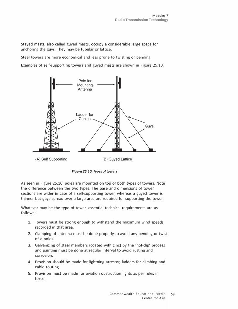
59Commonwealth Educational Media
Centre for Asia
Module: 7
Radio Transmission Technology
Stayed masts, also called guyed masts, occupy a considerable large space for
anchoring the guys. They may be tubular or lattice.
Steel towers are more economical and less prone to twisting or bending.
Examples of self-supporting towers and guyed masts are shown in Figure 25.10.
Figure 25.10: Types of towers
As seen in Figure 25.10, poles are mounted on top of both types of towers. Note
the difference between the two types. The base and dimensions of tower
sections are wider in case of a self-supporting tower, whereas a guyed tower is
thinner but guys spread over a large area are required for supporting the tower.
Whatever may be the type of tower, essential technical requirements are as
follows:
1. Towers must be strong enough to withstand the maximum wind speeds
recorded in that area.
2. Clamping of antenna must be done properly to avoid any bending or twist
of dipoles.
3. Galvanizing of steel members (coated with zinc) by the ‘hot-dip’ process
and painting must be done at regular interval to avoid rusting and
corrosion.
4. Provision should be made for lightning arrestor, ladders for climbing and
cable routing.
5. Provision must be made for aviation obstruction lights as per rules in
force.

Module: 7
Radio Transmission Technology
Commonwealth Educational Media
Centre for Asia
60
25.6.1 Location
In this subsection, you will learn about the location of towers. Location of towers
is important from the point of view of foundation and the coverage.
Since the objective of CR stations is to serve to a particular community residing in
a small concentrated area or an institution like a university campus, the choice of
location of the site is to a large extent limited to the available area. However,
important points worth noting for deciding the location are as follows:
• Location should be at the centre of the service area and preferably at the
elevated place.
• Location should be on firm ground.
• Land should not be low lying or marshy.
• An open space of about 6 x 6 M is required for the tower.
• The location of tower should be as near to the transmitter room as
possible.
• Location of guy anchors should be exactly at 120 degrees from each other.
25.6.2 Tower and Foundation
In this subsection, you will learn about the points to be considered while
deciding the tower and its foundation.
While erecting any tower, whether guyed or self-supporting, the design aspects
relating to the structural stability, dead load of tower and antenna system and the
wind speed must be considered.
It is a general practice that all the foundation and erection drawings are supplied
by the firm delivering the tower. Technicians/engineers supervising the erection
work must ensure that foundation and erection drawings are followed. The
quality of material used by the contractor should also be strictly checked to avoid
any untoward incident in future.
25.6.3 Mounting of Antenna and Cable on Tower
In this subsection, you will learn about the mounting of antenna and cable on
tower. Mounting of antenna is a highly skilled job. All personnel required to work
on high structures must undergo training before doing so. Normally, all the
antenna and other accessories are shipped in dismantled condition, which are
assembled on site.
The following instructions/guidelines must be followed while assembling and
mounting of an antenna:
• Personnel should be equipped with protective clothing, hard hats and
safety belts.

61Commonwealth Educational Media
Centre for Asia
Module: 7
Radio Transmission Technology
• Drawings and instructions for assembling on site must be understood
clearly.
• Spacing between the dipoles must be maintained as per the drawings
supplied by the manufacturer.
• A proper branch feeding cable for the respective dipole must be used as
per drawing.
• The supervisor at ground must explain and confirm that the rigger/mast
technician understands the instructions and guidelines in his language
properly.
• Proper connectors supplied by the manufacturer must be fixed correctly
as per instructions. Any wrong connector used or improperly fixed results
in mismatch and correspondingly a loss of RF power.
• For supporting the RF cables, horizontal and vertical racks must be used.
• The cable must be clamped at every metre of the length with cable
clamps of appropriate size.
• There should not be any sharp bends in RF cables. These bends may
damage the cables.
25.6.4 VSWR
Now let us discuss a very important parameter called VSWR (Voltage Standing
Wave Ratio), which is a measure of mismatch between the antenna and the cable.
Our main purpose is to transfer all the output power of the transmitter to the
antenna. To make this maximum power transfer possible, the characteristic
impedance of the coaxial cable should match with the input impedance of the
antenna.
When the impedance of the antenna differs from the specified value, part of the
energy is reflected back towards the transmitter as reflected wave. The
interaction between the forward and reflected waves sets up a voltage pattern in
the cable, which varies between maximum and minimum values as shown in
Figure 25.11.
VSWR is the ratio between the maximum and minimum values of voltage of the
standing wave.
Figure 25.11: Voltage Standing Wave Ratio

Module: 7
Radio Transmission Technology
Commonwealth Educational Media
Centre for Asia
62
Figure 25.11 shows a graphical representation of a standing wave formed by
interaction of the incident wave and the reflected wave at the point of mismatch.
The voltage standing wave has got a point of maxima and a point of minima. The
ratio of Vmax to Vmin is called the VSWR. If this matching is perfect, no power is
reflected back and VSWR is equal to unity (1:1).
You will learn more about VSWR measurements of antenna in Unit 29.
In the next section, you are going to learn about the protection of towers against
lightning.
25.7 Lightning Arrestor
In this section, you will learn about lightning arrestor, which is provided on top of
every tower to protect the tower, antenna system, coaxial cable, transmitter and
operating personnel from lightning.
Virtually, all masts are subject to lightning strikes, and in tropical areas this
incidence is high. The effects of lightning are well-known and the high levels of
electrical energy that are generated can result in severe damage to a transmitting
installation and even to the staff. It is not possible, of course, to prevent
occurrence of lightning strikes but their effects can be minimized by careful
design. Lightning tends to strike the highest well-defined point in an area. Masts
or towers, particularly those sited on hills, are more vulnerable. The discharge of
electrical energy associated with a lightning strike takes the form of a high-
current pulse that passes from the point of strike (the top of mast) to the point of
lower potential (usually the ground). The route taken by the discharge current
can be via more than one path. It is very difficult to predict the path taken by
lightning current. However, this path can be channelized by putting lightning
arrestor on top of the tower. Lightning arrestor is of a very highly conductive
material and connected to the nearest earth pit via copper strap. The earth pit is
preferably provided in the wettest part of the site between the mast and the
building. The purpose is to provide a low resistance path so that the voltage
induced in the arrestor due to lightning is immediately connected to the earth
before causing any damage to the equipment and staff. To ensure that lightning
currents flow directly to earth without damaging the equipment and staff, it is
essential that a transmitting station must have comprehensive grounding system.
You will learn about this grounding system in the next section.
25.8 Grounding
In this section, you are going to learn about the grounding system, which is an
essential requirement for protection of the equipment and the staff against
lightning.

63Commonwealth Educational Media
Centre for Asia
Module: 7
Radio Transmission Technology
The objectives of grounding are to:
1. Provide safety to the equipment and personnel against lightning.
2. Reduce losses in radiating antenna system.
Earthing System
The earthing system consists of an ordinary plate or an extensive network of
driven conductors and plates (called electrodes), buried deep into the soil. For
this purpose, earth pits giving very low resistance value are made. Different types
of earth pits are used. The most commonly used is GI Pipe earthing.
Alternate layers of salt and charcoal are added along with good earth to retain
moisture and achieve good conductivity. The purpose is to get very low-
resistance value of the order of less than 1 ohm. Where the ground is rocky, it
may not be possible to excavate a pit to sufficient depth and in that case several
smaller pits joined by copper straps should be used.
You will learn about the method of making earth connections and measurement
of earth conductivity in Unit 28 and in practical workshop.
Activity 25.4
During your visit to a CR station, take a look at the dummy load, coaxial cable,
antenna system, tower, lightning arrestor and grounding system used at that
station. Note down the specifications for the important parameters of items
studied in this unit. Fill in the details in the proforma given below. This will
help you identify the types of these items and visualize their significance. You
can refer to manufacturers’ manuals in this regard.
A. Dummy load
Sl. No. Parameter Specification
1 Make
2 Model no.
3 Power rating
4 Input impedance
5 Type of cooling

Module: 7
Radio Transmission Technology
Commonwealth Educational Media
Centre for Asia
64
B. Coaxial cable
Sl. No. Parameter Specification
1 Size of cable
2 Length of cable
3 Make4Model no.
5 Power rating
6 Characteristic impedance
7 Type of connectors
C. Types of antenna
Sl. No. Parameter Specification
1 Type
2 Make
3 Model
4 Number of radiating
elements used
5 Polarization used
D. Supporting towers and mounting of antenna system
Sl. No. Parameter Specification
1 Type of tower
2 Height of tower
3 Height of antenna
4 Mounting of antenna
5 Foundation of tower
E. Lightning arrestor and grounding system
Sl. No. Parameter Observations
1 Number of earth pits used
2 Type of earth pit
3 Watering arrangement
4 Use of lightning arrestor
5 Grounding of tower

65Commonwealth Educational Media
Centre for Asia
Module: 7
Radio Transmission Technology
25.9 Let Us Sum Up
In this unit on FM antenna and coaxial cable, you have learnt that:
• Dummy load is required for testing the transmitter before it is connected
to the antenna. The dummy load converts the RF power into heat without
any RF radiations. The power rating of dummy load should not be less
than the transmitter output power.
• RF coaxial cable is used to transfer transmitter output power to the
antenna system. Feeder cables mostly used are low-loss cables. Power
rating and attenuation are both frequency dependent. Power rating
decreases as the frequency increases, whereas attenuation increases
with increase in frequency.
• The antenna system is required to convert RF output of the transmitter
into electromagnetic waves. We have also discussed various types of
antennae and classified them into different categories according to
design, construction and mounting arrangements. Important parameters
of FM antennae are horizontal and vertical radiation patterns and the
VSWR (Voltage Standing Wave Ratio). VSWR is the measure of degree of
mismatch at the input of the antenna.
• Towers are required to mount the antenna system. We have, discussed
two types of towers, namely self-supporting and guyed towers. Self-
supporting towers are more stable and require smaller area for
foundation. Foundation and structural designs are based on height of
tower, dead load and wind load of antennae.
• To protect tower, antenna cable and operating staff from lightning, use of
lightning arrestor and grounding of tower and cable is necessary. The
tower, cable and body of the transmitter and electrical panels should be
connected to the nearest earth pit by use of double copper strips. The
location of the earth pit should be preferably in the wettest place to
retain moisture and as near to the tower as possible. The earth resistance
of earth pit should be less than one ohm.
Module: 7
Radio Transmission Technology
Commonwealth Educational Media
Centre for Asia
66
25.10 Model Answers to Activities
Answers to questions given in Activities 25.1 to 25.3.
Activity 25.1
1. Dummy load is provided to check the output and performance of the
transmitter before it is connected to the antenna.
2. Non-inductive resistors are used in the construction of a dummy load
because dummy load should dissipate the RF power into heat and not
radiate into air medium.
3. Large surface area and the fins help quick transfer of heat produced in the
resistor of dummy loads into the room with raising the temperature.
4. Input impedance of the dummy load should be equal to the output
impedance of the transmitter. It is equal to 50 ohms normally.
5. When the high power transmitters are tested on the dummy load, the
heat transfer rate of convection or air cooled is not fast. Water-cooled or
oil-cooled dummy loads are more efficient in quick transfer of heat.
Activity 25.2
1. The attenuation offered by low-loss cable is very less and as a result
maximum power of transmitter can be fed into the antenna.
2. The dielectric material usually used is foam polyethylene.
3. The characteristic impedance of a coaxial cable is the ratio of voltage to
the current for a single propagating wave (frequency).
4. Attenuation of a coaxial cable = 10 log P1/ P
2 where P
1 is input power and
P2
is the power reaching at other end. Substituting the given values, we
get attenuation = 10 log 50/25 = 10 log 2 =10x 0.3010 = 3 dB
5. The average power rating of a cable is inversely proportional to the
frequency of operation. If frequency increases, average power decreases
and vice versa.
Activity 25.3
1. It indicates that two dipoles have been used. It is a pole mounted
antenna. Its polarization is vertical.
67Commonwealth Educational Media
Centre for Asia
Module: 7
Radio Transmission Technology
2. It will be called circular polarization.
3. From the interpretation of horizontal pattern, we can know the field
strength in all the radial direction from the location of the antenna.
4. With a single antenna, the transmitter power required will be double
than what is used with a 2-bay antenna for the same coverage.
5. Using the equation, Wavelength = Velocity of light in meters/frequency in
Hz = 3x 10⁸ / 100 X 106 = 300/100 = 3 m. Length of half-wave dipole = ½ x 3 =
1.5 m
Activity 25.4
The information gathered in the activity should be your own and hand-on
experiences.

Module: 7
Radio Transmission Technology
Commonwealth Educational Media
Centre for Asia
68
Propagation and Coverage
UNIT 26
Structure
26.1 Introduction
26.2 Learning Outcomes
26.3 What is Spectrum?
26.4 Layers of Atmosphere and Radio Wave Propagation
26.4.1 Troposphere
26.4.2 Stratosphere
26.4.3 Ionosphere
26.4.4 Ground Wave/Sky Wave/Space Wave
26.4.5 Effects of Wave Propagation in Different Medium
26.5 Factors Affecting Coverage and Shadow Areas
26.5.1 Factors Affecting Coverage
26.5.2 What is ERP?
26.5.3 Shadow Areas
26.6 Topography
26.7 Signal Requirements and Coverage Planning Parameters
26.7.1 Transmission Characteristics (ITU-R BS-450-2)
26.7.2 Channel Spacing
26.7.3 Minimum Usable Field Strength (Emin
)
26.7.4 Radio Frequency Protection Ratio
26.8 Field Strength Measurements and Drawing an Actual Coverage Map
26.8.1 Field Strength Meter
26.8.2 Drawing an Actual Coverage Map of an FM Transmitter
26.9 Let Us Sum Up
26.10 Model Answers to Activities
26.11 Additional Readings

69Commonwealth Educational Media
Centre for Asia
Module: 7
Radio Transmission Technology
26.1 Introduction
In the previous unit ‘FM-Antenna on RF Cable’, you learnt about the components,
which are used after the output stage of transmitter. These include dummy loads
used for internal testing of transmitter; type of coaxial cable that connects the
transmitter output to the antenna; types of antenna used for radiation of RF
signal; tower and mounting of an antenna; VSWR; lightning arrestor; grounding;
etc. The coaxial cable, also known as RF feeder line, carries the transmitter power
from its output up to the antenna, which is normally mounted on top of the
tower, and from there the RF propagates in various directions.
In this unit, you will learn about propagation and coverage of RF signals,
particularly, FM broadcasting in VHF band. In order to have better understanding
on propagation, we need to know about various RF frequency bands and their
ranges, which are described under Section 26.3. The RF signals are radiated from
the antenna and they propagate in different directions. RF signals, depending
upon their frequency band, propagate through various layers of atmosphere. In
Section 26.4, you will learn what the various layers of atmosphere are and how
different RF signal behaves while passing through these layers. This section also
mentions about phenomena like reflection, refraction, diffraction, ducting, etc.,
which RF signal encounters while propagating through various layers of
atmosphere. In Section 26.5, you will learn about radio coverage and how it is
affected by various factors like frequency, power of transmitter, gain of antenna,
height of antenna, terrain condition, presence of environmental noise and also
effective radiated power (ERP), which is a very common term used in planning of
coverage. This section also defines shadow areas/shadow zones, which occur
when RF signals are blocked by terrain condition or poor availability of signal.
Shadow regions can be minimized and radio coverage can be maximized by
proper selection of site where the antenna can be located at the highest available
point/place. Such locations can be identified by examining the topography of the
area and analysing toposheets of that particular region. In Section 26.6, you will
learn about topography including toposheets and their usage. For planning of FM
radio coverage, it is essential to understand the ITU-defined planning
parameters, like channel spacing, minimum usable field strength, protection
ratio, etc. These parameters are defined in Section 26.7. Field strength
measurement is very commonly carried out for checking availability of radio
coverage around a transmitter. Learning this in Section 26.8 and also drawing a
radio coverage map by plotting the minimum required field strength measured
around the transmitter antenna will help you have good understanding of the FM
transmitter of a CR station.
You will take about 6 hours to complete this unit.

Module: 7
Radio Transmission Technology
Commonwealth Educational Media
Centre for Asia
70
26.2 Learning Outcomes
After going through this unit, you will be able to:
• define:
(i) RF spectrum and various bands.
(ii) Various layers of atmosphere and what kind of radio waves
propagates through them.
(iii) The parameters used for coverage planning of FM radio network.
• list and describe:
(i) The factors responsible for affecting radio coverage and creation of
shadow region.
(ii) Various parameters used for planning of RF coverage network.
• analyse:
(i) the toposheet for selection of optimal location for transmitter
tower to provide better coverage.
(ii) the field strength measurement data and check availability of
desired signal for adequate radio coverage.
• undertake field strength measurements survey and draw a coverage map.
26.3 What is Spectrum?
Radio wave and spectrum subjects have already been described in detailed under
Sections 6.3 and 6.4 of Unit 6 (Module 2). However, to refresh your memory, a
brief overview on this subject is given below.
Electromagnetic spectrum is used to carry electromagnetic signals through space.
The radio frequency spectrum, which is a part of electromagnetic spectrum, is
shared by various radio communication services for variety of applications
including public telecommunication services, aeronautical/maritime safety
communications, radio and television broadcasting, radars, seismic surveys,
rocket and satellite launching, earth exploration, natural calamities forecasting,
etc.
The whole of the electromagnetic spectrum covers a huge range of frequencies.
Radio frequencies themselves extend over a very large range as well. The range is
further divided into different frequency bands as given in Table 1. Frequencies
above 1 GHz are normally known as microwaves. As per National Frequency
Allocation Plan (NFAP), 87–108 MHz band is used for FM radio broadcasting in
India.

71Commonwealth Educational Media
Centre for Asia
Module: 7
Radio Transmission Technology
Table 1: RF Spectrum Bands
From To RF spectrum band
3 kHz 30 kHz Very low frequency (VLF)
30 kHz 300 kHz Low frequency (LF)
300 kHz 3 MHz Medium frequency (MF)
3 MHz 30 MHz High frequency (HF)
30 MHz 300 MHz Very high frequency (VHF)
(FM Band 87 – 108 MHz)
300 MHz 3 GHz Ultra high frequency (UHF)
3 GHz 30 GHz Super high frequency (SHF)
30 GHz 300 GHz Extra high frequency (EHF)
Some bands used in microwaves:
Bands Frequency range Bands Frequency range
L band 1 to 2 GHz Ku band 12 to 18 GHz
S band 2 to 4 GHz K band 18 to 26.5 GHz
C band 4 to 8 GHz Ka band 26.5 to 40 GHz
X band 8 to 12 GHz
RF spectrum is a valuable, scarce and finite natural resource that is needed for
various services and applications. Therefore, its utilization is to be planned
scientifically and carefully so that the scarce resource is managed effectively and
optimally.
Activity 26.1
To complete this activity, you may need about 10 minutes including writing
down the answers in the space provided below.
Question: 1 What is a microwave? Name some radio services that operate in
microwave bands.
Question: 2 What is NFAP? Who is responsible for preparing this document?
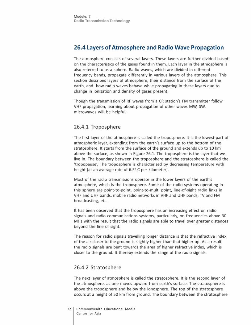
Module: 7
Radio Transmission Technology
Commonwealth Educational Media
Centre for Asia
72
26.4 Layers of Atmosphere and Radio Wave Propagation
The atmosphere consists of several layers. These layers are further divided based
on the characteristics of the gases found in them. Each layer in the atmosphere is
also referred to as a sphere. Radio waves, which are divided in different
frequency bands, propagate differently in various layers of the atmosphere. This
section describes layers of atmosphere, their distance from the surface of the
earth, and how radio waves behave while propagating in these layers due to
change in ionization and density of gases present.
Though the transmission of RF waves from a CR station’s FM transmitter follow
VHF propagation, learning about propagation of other waves MW, SW,
microwaves will be helpful.
26.4.1 Troposphere
The first layer of the atmosphere is called the troposphere. It is the lowest part of
atmospheric layer, extending from the earth’s surface up to the bottom of the
stratosphere. It starts from the surface of the ground and extends up to 10 km
above the surface, as shown in Figure 26.1. The troposphere is the layer that we
live in. The boundary between the troposphere and the stratosphere is called the
‘tropopause’. The troposphere is characterized by decreasing temperature with
height (at an average rate of 6.5o C per kilometer).
Most of the radio transmissions operate in the lower layers of the earth’s
atmosphere, which is the troposphere. Some of the radio systems operating in
this sphere are point-to-point, point-to-multi point, line-of-sight radio links in
VHF and UHF bands, mobile radio networks in VHF and UHF bands, TV and FM
broadcasting, etc.
It has been observed that the troposphere has an increasing effect on radio
signals and radio communications systems, particularly, on frequencies above 30
MHz with the result that the radio signals are able to travel over greater distances
beyond the line of sight.
The reason for radio signals travelling longer distance is that the refractive index
of the air closer to the ground is slightly higher than that higher up. As a result,
the radio signals are bent towards the area of higher refractive index, which is
closer to the ground. It thereby extends the range of the radio signals.
26.4.2 Stratosphere
The next layer of atmosphere is called the stratosphere. It is the second layer of
the atmosphere, as one moves upward from earth’s surface. The stratosphere is
above the troposphere and below the ionosphere. The top of the stratosphere
occurs at a height of 50 km from ground. The boundary between the stratosphere

73Commonwealth Educational Media
Centre for Asia
Module: 7
Radio Transmission Technology
and the ionosphere is called the stratopause. These are indicated in Figure 26.1.
The stratosphere has either constant or slowly increasing temperature with
height.
Figure 26.1: Layers of atmosphere and their distances from earth surface
26.4.3 Ionosphere
The ionosphere is the third layer of the atmosphere, as one moves upward from
earth’s surface. This layer is ionized by solar wind. It has practical importance
because, among other functions, it influences radio propagation to distant places
on the earth. This layer basically starts from the height of 50 km above the earth
and extends up to the height of about 600 km. In case of radio waves passing
through this layer or somehow penetrating into it, they will be affected by the
specific phenomena of this layer. Some of the communication systems that
experience these effects are those working in MF and HF radio transmission
bands as well as satellite and space communication systems where one or both

Module: 7
Radio Transmission Technology
Commonwealth Educational Media
Centre for Asia
74
end point terminals are located on the ground. The ionosphere is sub-divided
into several layers as described below and also shown in Figure 26.2.
D Layer
The D layer is located above the stratosphere. It is the innermost layer of
ionosphere. Its range is from 50 km to 115 km with reference to the surface of the
earth. The intensity of ionization is higher in the D layer because it is composed
of the heavier gasses. High-frequency (HF) radio waves are not reflected by the D
layer but suffer loss of energy therein. This is the main reason for absorption of
HF radio waves, particularly, at 10 MHz and below with progressively smaller
absorption as the frequency gets higher. The absorption is small at night and
greatest about midday. The layer reduces greatly after sunset. A common
example of the D layer in action is the disappearance of distant MW broadcast
band stations in the daytime.
E Layer
The E layer is located above the D layer. It is the middle layer of ionosphere. Its
range is from 115 to 160 km from the surface of the earth. The intensity of
ionization is lesser in the E layer as compared to D layer because it is composed of
less heavy gasses. This layer can only reflect radio waves having frequencies
lower than about 10 MHz and may contribute a bit to absorption on frequencies
above.
Sporadic-E (Es)
The Es layer (sporadic E layer) is characterized by small and thin clouds of intense
ionization. Sporadic-E events may last from just a few minutes to several hours.
This propagation occurs most frequently during summer months.
Figure 26.2: Layers of ionosphere and distances from the earth surface
75Commonwealth Educational Media
Centre for Asia
Module: 7
Radio Transmission Technology
F Layer
The F layer extends from about 200 km to about 600 km above the surface of the
earth. It is the densest point of the ionosphere, which implies signals penetrating
this layer will escape into space. The F layer consists of one layer at night, but
during the day, a deformation often forms in the profile that is labelled as F1 and
the other part as F2.
F1 Layer
The F1 layer is located above the E layer. Its range is from 200 to 250 km with
respect to the earth. The intensity of ionization is lesser in the F1 layer with
respect to E layer.
F2 Layer
This layer is located above the F1 layer. Its range is from 250 km to 400 km with
respect to the earth. The intensity of ionization is lesser in F2 layer with respect
to F1 layer. The F2 layer remains by day and night responsible for most skywave
propagation of radio waves, facilitating high frequency (HF, or shortwave) radio
communications over long distances.
26.4.4 Ground Wave/Sky Wave/Space Wave
Radio waves travel from one point to another (e.g.,a transmitter to a receiver) by
different ways. These are mainly ground waves, sky waves and space or
tropospheric waves.
The ground waves travel closer to the surface of the earth. The sky wave
propagation, usually called ionospheric propagation, results due to bending of
wave-path through ionosphere. This method of propagation accounts for long
distance radio communication through shortwave both, during day and night time
and also through medium wave during night.
Space wave represents energy that travels from the transmitting to the receiving
antenna through earth’s troposphere. Space wave propagation becomes essential
in VHF bands because ground wave is attenuated to a negligible amplitude within
a few hundred metres, while the ionosphere is not able to reflect any energy
back to the earth in VHF range.
26.4.5 Effects of Wave Propagation in Different Media
When lights travel from one medium to another, three things happen: (i) some
lights are reflected, (ii) some lights are absorbed and (iii) some get refracted.
Similarly, when radio wave propagates, the following can occur when the wave

Module: 7
Radio Transmission Technology
Commonwealth Educational Media
Centre for Asia
76
passes from one medium to another:
i) Reflection: some waves get reflected back into the same medium.
ii) Absorption: some waves get absorbed by the medium.
iii) Refraction: some waves get transmitted into the second medium at a
different direction and velocity.
However, when a radio wave encounters an obstacle on its propagation path, it
may bend around the obstacle. This bending phenomenon is called diffraction.
Also, when a wave propagates in troposphere, another special phenomenon
‘ducting’ occurs due to temperature inversion.
Reflection
Reflected waves are neither transmitted nor absorbed, but are reflected from the
surface of the medium they encounter. The basic analogy is similar to reflection
of light by a mirror. If a wave is directed against a mirror, the wave that strikes the
surface is called the incident wave, and the one that bounces back is called the
reflected wave. This also occurs when a wave is transmitted skyward, reflect off
the ionosphere, and returns to a receiving station. The angle of reflection equals
the angle of incidence. Reflection of wave is illustrated in Figure 26.3, where the
incident wave forms angle i to normal reflected at an angle r and travels in a
different direction.
Figure 26.3: Reflection of wave
Refraction
The radio waves propagating in the earth’s atmosphere always experience the
wave refraction phenomenon. As the height increases, the air density and
consequently its refractive index decreases. This non-homogeneous
characteristic of air in the atmosphere causes deviation in the wave propagation
path, so that they do not travel further in a straight direction. When the rate of

77Commonwealth Educational Media
Centre for Asia
Module: 7
Radio Transmission Technology
refractive index changes linearly, the ray path would be an arc of a circle. Figure
26.4a shows a simple case of refraction where the refracted wave bends inward
when it travels from one medium into another. The bending phenomenon is
clearly visible. In Figure 26.4b, the same phenomenon is described in detail
where the wave from medium 1 having refractive index n1 travels to medium 2
with refractive index n2. If the refractive index of medium 2 is higher than
medium 1 then the wave will bend inward. If the refractive index of medium 2 is
lower, it would bend outward. If we draw a normal at the point where the wave
from medium 1 enters into medium 2, then it forms an angle α known as angle of
incidence. In medium 2, the refracted wave bends inward forming angle of
refraction β.
Figure 26.4a: Refraction of wave
Figure 26.4b: Refraction of wave with angle of refraction β

Module: 7
Radio Transmission Technology
Commonwealth Educational Media
Centre for Asia
78
Figure 26.4c shows how short wave frequencies get refracted from the
ionosphere and return to the earth’s surface at a longer distance. Because of this
phenomenon, short wave signals travel several thousands of kilometres.
Figure 26.4c: Short wave frequencies get refracted by ionosphere and travel longer distance
Diffraction
When a radio wave encounters an obstacle in its path, it bends around the
obstacle. This bending is called diffraction, and results in a change of direction of
part of the energy from the normal line-of-sight path. Figure 26.5 shows a wave
that is diffracted after it came across a partial obstructed object. When a wave
front strikes the edge of an object, as shown in the figure, it bends inward and
travels further in a different direction. Before reaching the object, the wave front
was travelling in a horizontal direction and after passing through the edge of the
object, it started travelling downward. This phenomenon is called diffraction.
Figure 26.5: Diffraction of wave

79Commonwealth Educational Media
Centre for Asia
Module: 7
Radio Transmission Technology
Ducting
Ducting is one of the propagation phenomena that happen in the troposphere.
Tropospheric ducting occurs when a radio signal is reflected off the troposphere
and continues on a path that allows the signal to travel much farther than it
normally would. This occurs when the temperature in the atmosphere
experiences an inversion. When a temperature inversion occurs, radio waves that
would normally continue into space beyond the earth’s atmosphere are instead
reflected and they continue to follow the curvature of the earth. Radio waves
have been able to travel in excess of 1,000 km because of tropospheric ducting.
TV signals travel longer distance over sea surface because of ducting. Figure 26.6
shows how the radio waves propagate because of total internal reflection
between two layers forming a duct above the surface of the earth.
Figure 26.6: Ducting
Activity 26.2
To complete this activity, you may need about 15 minutes including writing
down answers in the space provided below.
Question: 1 Name various types of radio communication systems that operate
in VHF band in India.
Question: 2 What are the various effects that take place when VHF signal
propagates in the troposphere?
26.5 Factors Affecting Coverage and Shadow Areas
RF signals are transmitted from the antenna of radio transmitters. These RF
signals, depending on the frequency of operation, propagate through different
layers of the atmosphere and reach various places. Radio receivers help in
detecting these signals and reproduce the audio frequencies after demodulating
them. However, the receiver can only be able to detect the signals that are above

Module: 7
Radio Transmission Technology
Commonwealth Educational Media
Centre for Asia
80
the minimum usable field strength. Availability of the area around the
transmitting station which gets the signal of this strength or more is known as
radio coverage area. Places where these signals do not reach from the transmitter
due to obstruction of propagation condition are called shadow zones or shadow
areas. The following sections explain these phenomena in detail.
26.5.1 Factors Affecting Coverage
Transmitter antenna radiate energy in all directions. Depending upon the design
of antenna (e.g., directional or omni-directional), the intensity of energy
radiation varies in different directions with respect to distance. As the distance
from the location of the antenna increases, the intensity of the received signal
decreases. The distance where the strength of received signal is just sufficient for
the receiver to detect it without any interference is called radio coverage range.
These distances from the transmitter/antenna in different directions around the
antenna define radio coverage range.
RF coverage or availability of desired level of RF signal in a particular target area
gets affected by various factors. Some of these major factors that affect the
coverage of RF signals are as follows:
• The frequency on which the transmitter is operating
• The effective radiated power of the transmitting station, that is, ERP
• The type and design of antenna
• The height and location of the antenna
• The terrain profile and condition
• The amount of electromagnetic noise
Each of these above factors affects radio coverage and is taken into consideration
in determining how far the radio signal would be able to provide effective
coverage.
Frequency on which the transmitter is operating
Frequencies in higher order bands cover lesser area. In case of medium wave
transmissions, the lower order band, e.g., around 600 kHz, provides wider
coverage than higher order bands, say at 1500 kHz, under similar ground
conditions (conductivity). An FM transmitter operating in VHF FM band (87 – 108
MHz) provides almost similar coverage.
Effective rated power of the transmitter
As a general rule, it can be said that the coverage of radio transmitter increases
with its output power. The higher the power, greater is the coverage distance.
Also since VHF is a line-of-sight propagation, the coverage is restricted by

81Commonwealth Educational Media
Centre for Asia
Module: 7
Radio Transmission Technology
availability of line-of-sight. As such, increasing transmitter power beyond a
certain point may not be able to increase its coverage range. However, in actual
terms, it is the effective radiated power (ERP) of the transmitting station (which
includes the contribution of the antenna system) that determines the coverage
and not the transmitter power alone. You will learn about ERP in detail later in
this subsection.
Type and design of antenna
The type and design of an antenna decide its gain. This gain increases the ERP,
e.g., a 10 kW FM transmitter having an antenna of gain 3 dB would radiate 20 kW
as ERP. A directional antenna has more gain in a particular direction, and thereby
increases the range or coverage in that direction.
Antenna height and location
The most critical coverage factor is the height and location of the antenna. This is
because the range of a radio coverage is theoretically limited to the radio horizon
as reached by the radio antenna. Basically, the higher the height of the antenna,
the greater the area it will cover. Therefore, FM antennae installed on hilltops
provide wider coverage.
Terrain profile and condition
As radio waves follow a line-of-sight path, terrain variations can cause
obstruction to propagation. Hills and valleys or any kind of high-rise structure that
come in the direction of the line-of-sight path obstruct propagation. In such
cases, if we increase the antenna height, we can reduce such obstruction, and
thereby increase coverage.
Amount of electromagnetic noise
Presence of electromagnetic noise, industrial noise, or environmental noise
around the receiver affects detection of weak RF signals and thereby affects radio
coverage.
26.5.2 What is ERP?
Most of us are well aware of transmitter power, which the transmitter delivers to
the feeder/RF cable that is connected to the antenna. However, this power may
not be the same what the antenna delivers or radiates. It is mainly because of
two factors: (i) the feeder/RF cable including multiplexer/diplexer/connectors
causes some losses and (ii) the antenna may provide some gain depending upon
its design. This gain of antenna varies with its type and directivity. Therefore, the
ERP includes all gain and loss factors on the transmitting side and usually
expressed in dBm, or dBw, or dBkw, etc. In fact, ERP is the product of the
transmitter output power and antenna gain in the desired direction taking into
account all losses caused by the RF feeder, connectors, etc.

Module: 7
Radio Transmission Technology
Commonwealth Educational Media
Centre for Asia
82
Mathematically, ERP can be calculated as:
ERP = (Transmitter Power – Feeder/RF cable loss) x Antenna gain
For example, a 100w FM transmitter having a 30-meter long RF
feeder cable causes a loss of 1dB and the gain of antenna is 4dB.
Then, its ERP will be:
Transmitter power – Feeder cable loss + Antenna gain (all in dB)
= 100w (or 20 dBw) – 1 dB + 4 dB
= 23 dBw
= 200w (3 dB gain doubles the power)
26.5.3 Shadow Areas
In FM broadcasting network, reception of radio service gets hampered because of
inadequate signal or any obstruction between the transmitting station and the
targeted areas. These areas are called shadow zones or shadow areas. As an
example, if the transmitter in a valley is located on one side of a hill, the other
side will have no RF signal and thereby creates shadow areas.
Activity 26.3
To complete this activity, you may need about 5 minutes.
Qestion: 1 Find out the ERP of a transmitter having output power 200 w,
losses due to feeder cable and joints 1.5 dB and antenna gain 4.5
dBi.
26.6 Topography
Topography is a broad term used to describe the detailed study of the earth’s
surface. It is a detailed description of a place or region located on a map. While
topography includes vegetative and man-made features, it more commonly
refers to a horizontal point of latitude and longitude. This includes changes in the
surface such as mountains and valleys as well as features such as rivers, roads and
buildings. Topography is closely linked to the practice of surveying, which is the
practice of determining and recording the position of points in relation to one
another.

83Commonwealth Educational Media
Centre for Asia
Module: 7
Radio Transmission Technology
Toposheet
India, with an area of 32,87,263 km2, is covered by both topographical and
geographical maps. The topographical maps are on sufficiently large scale of
1:25,000, 1:50,000, which are ideally suited for the professional work of
geologists, geographers, foresters, engineers, planners, tourists, mountaineers,
etc. On the other hand, the geographical maps are on such a small scale of less
than 1:2,50,000 that they are useful mainly for synoptic views.
India is covered by nearly 385 toposheets on 1:2,50,000 scale, which are also
called degree sheets. Each degree sheet has 16 toposheets of 1:50,000 scale and
the whole of the country is covered by 1:50,000 rigorous metric surveys in more
than 5,000 toposheets. Each 1:50,000-scale sheet contains four 1:25,000-scale
sheets. Guide maps on scale of 1:10,000 and smaller are available for towns and
cities in various states.
Topographic maps provide the graphical portrayal of objects present on the
surface of the earth. These maps provide the preliminary information about a
terrain and thus are very useful for engineering works, including planning of radio
coverage network. For most part of India, topographic maps are available, which
are prepared by the Survey of India. To identify a map of a particular area, a map
numbering system has been adopted by the Survey of India.
For broadcast radio network planning, toposheets are useful for locating highest
points where an antenna can be installed so that maximum coverage is achieved.
However, since CR stations have to be located near the area of the target
community, the coverage planning has to take into account the topography of a
target area with a smaller community, which may not have much variation in
topology.
26.7 Signal Requirements and Coverage Planning
Parameters
The coverage planning of an FM transmitter in VHF band-II (for FM broadcasting in
India it is 87–108 MHz) is a complex process. Preparation on planning of FM
network requires understanding of minimum usable field strength, protection of
wanted signal from other transmitters, noise protection requirements for city and
rural areas, etc. To get a clear understanding of coverage planning, these
parameters are explained below.
26.7.1 Transmission Characteristics (ITU-R BS-450-2)
ITU has defined FM transmission characteristics as per its recommendation BS-
450-2. These characteristics define permissible range of parameters like AF
bandwidth, maximum deviation, bandwidth of emission, pre-emphasis,

Module: 7
Radio Transmission Technology
Commonwealth Educational Media
Centre for Asia
84
maximum spurious emission, etc. These terms were defined and explained in
Unit 23. However, for easy reference, these are summarized below:
AF bandwidth : 15 kHz
Maximum deviation : ± 75 kHz (Stereo Multiplex Signal)
Bandwidth of emission : 180 kHz
Pre-emphasis : 50 µ sec
Frequency tolerance : 2000 Hz
Maximum spurious emission : – 60 dBc (60 dB below carrier)
26.7.2 Channel Spacing
Channel spacing is the difference in frequency between successive FM carriers. It
is measured in kHz.
• Monophonic reception : optimum between 75 kHz and 100 kHz
• Stereophonic reception : optimum between 100 kHz and 150 kHz
• Optimum channel spacing : 100 kHz (used in India)
• Minimum frequency separation between transmitters co-located in the
same city is 400 kHz (theoretically). But in India 800 kHz separation is
presently being used between two transmitters operating in the same city
in most of the places.
26.7.3 Minimum Usable Field Strength (Emin
)
For FM radio broadcasting, ITU has given, vide its Recommendation BS-450,
different level of signal strength that are required for providing coverage to
different geographical locations (Rural, Urban and Semi-Urban). ITU has also
defined these parameters according to the type of reception, that is, mono or
stereo as given in Table 2. While working out these recommendations, noise
levels in different set of locations namely rural, urban and large city have been
taken into consideration.
Table 2: Minimum Usable Field Strength
Monophonic Stereophonic
Reception Reception
Rural Area 48 dB(mv/m) 54 dB(mv/m)
Urban Area 60 dB(mv/m) 66 dB(mv/m)
Large City 70 dB(mv/m) 74 dB(mv/m)

85Commonwealth Educational Media
Centre for Asia
Module: 7
Radio Transmission Technology
The field strength received from a given transmitter varies not only with location,
but also with time. Therefore, FM radio services are normally planned to be
available for 99% of the time in the case of national networks and 95% of the time
for local services.
26.7.4 Radio Frequency Protection Ratio
A protection ratio is the required difference in field strength between a wanted
and an interfering signal, and is normally expressed in dB. The required ratio falls
as the frequency separation between the two stations increases, and is tabulated
in Table 3.
Table 3: Protection Ratio
Frequency Spacing Monophonic Stereophonic
(kHz) Steady Troposphere Steady Troposphere
0 36 28 45 37
100 12 12 33 25
200 6 6 7 7
300 –7 –7 –7 –7
400 –20 –20 –20 –20
26.7.5 CRS Frequencies
For proper operation of CR stations, WPC has identified specific frequency spots.
These are 90.4, 90.8 and 107.8 MHz. As such, normally a CRS is allotted one
frequency out of these frequencies. In addition, 91.2 MHz is also allotted
wherever it is possible to do so.
Activity 26.4
To complete these activities, you may need about 10 minutes including writing
down the answers in the space provided below.
Question:1 What is the channel spacing in VHF FM broadcasting? In USA, UK,
Japan and India, what channel spacing is used in FM channels?
Question:2 Define protection ratios for co-channels (channels with same
frequency repeated and at a different location) for stereophonic
transmission in steady state.

Module: 7
Radio Transmission Technology
Commonwealth Educational Media
Centre for Asia
86
26.8 Field Strength Measurements and Drawing an Actual
Coverage Map
Measurement of field strength is important and essential to ensure effective
planning and coverage of radio services, be it SW, MW or FM. Field strength
meters measure the strength of RF signal available, which indicates whether the
strength is good enough for desired reception. A field strength meter is quite
commonly used for this purpose and therefore it is necessary to understand its
operation and use. Also, it is necessary to learn the process of plotting and
preparing of actual coverage map from these readings.
26.8.1 Field Strength Meter
A field strength meter is a microvolt meter or test receiver coupled with a
suitable pick-up device (antenna) for measuring electrical and magnetic field
strength.In broadcasting, it is used for propagation measurements, determination
of coverage, radiation patterns of antennae, etc.
Basic Principles
A field strength meter comprises the following three essential parts:
• Pick-up device or transducer (antenna)
• Voltage measuring device
• Built-in calibration oscillator
Field strength is measured by comparing the voltage induced in the antenna
circuit with the output of the built-in calibration oscillator.
Field Strength Measurement
A typical field strength measurement set-up is shown in Figure 26.7. It comprises
a field strength meter, an antenna and a connecting cable. The antenna is
connected to the input of the field strength meter through a cable. The
measurement is carried out in two steps:
• First, the detector output of the receiver is adjusted up to certain
indication Eo dB (µv/m) with the help of the attenuator.
• Second, the known output from calibration oscillator is fed to the receiver
and the attenuator value is adjusted so as to get same output in the
indicating device, that is, Eo dB (µv/m).
Measurement Range: Typical range –10 to + 160 dBµ

87Commonwealth Educational Media
Centre for Asia
Module: 7
Radio Transmission Technology
Figure 26.7: Field strength measurement set-up
Normally, field strength measurements are recorded when the CR station is set
up or there is an issue of coverage not being satisfactory.
26.8.2 Drawing an Actual Coverage Map of an FM Transmitter
Let us carry out field strength measurement survey of a 300 w FM transmitter
located in North-West Delhi to ascertain stereo and monophonic FM coverage.
Since Delhi is an urban city, the desired field strength value should be 74 dB µv/m
and 70 dB µv/m, respectively, for stereophonic and monophonic transmissions.
These field strength values are measured and verified in a given direction at a
particular distance from the FM transmitter. These distances for both stereo and
mono transmissions are noted as shown in Table 4.
Table 4: Field strength measurement and coverage distance of 300 w FM
transmitter
Angle/Direction Distance in km for
Stereo (74 dB µv/m) Mono (70 dB µv/m)
1 0o / East 6.1 9.2
2 45o / North-East 6 8.9
3 90o / North 6.7 10.1
4 135o / North-West 6.2 10.3
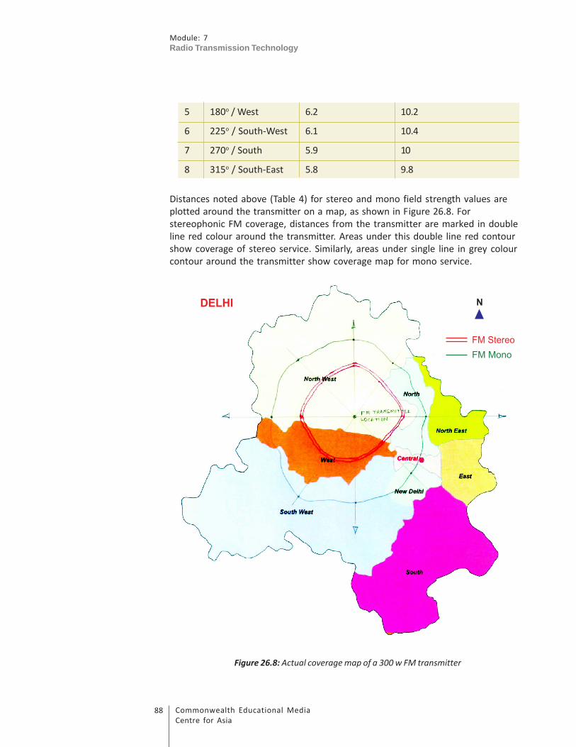
Module: 7
Radio Transmission Technology
Commonwealth Educational Media
Centre for Asia
88
5 180o / West 6.2 10.2
6 225o / South-West 6.1 10.4
7 270o / South 5.9 10
8 315o / South-East 5.8 9.8
Distances noted above (Table 4) for stereo and mono field strength values are
plotted around the transmitter on a map, as shown in Figure 26.8. For
stereophonic FM coverage, distances from the transmitter are marked in double
line red colour around the transmitter. Areas under this double line red contour
show coverage of stereo service. Similarly, areas under single line in grey colour
contour around the transmitter show coverage map for mono service.
Figure 26.8: Actual coverage map of a 300 w FM transmitter

89Commonwealth Educational Media
Centre for Asia
Module: 7
Radio Transmission Technology
Activity 26.5
To complete this activity, you may need about 10 minutes including writing
down the answer in the space given below.
Question: 1 Explain the procedures for measurement of field strength?
26.9 Let Us Sum Up
RF spectrum is defined in the range from 3 kHz to 300 GHz. This is further divided
into various bands known as VLF, LF, HF, VHF, UHF, SHF and EHF. A spectrum over 1
GHz is known as a microwave.
Propagation of RF waves takes place in various layers of the atmosphere. These
layers are known as troposphere, stratosphere and ionosphere. Most of the
communication systems operate in troposphere. However, HF propagation
through ionosphere helps in providing SW broadcast to longer distances.
Radio waves, while propagating in various medium (e.g., in troposphere),
encounter reflection, refraction, diffraction, ducting, etc. These effects help
operation of different types of communication systems for various purposes, e.g.,
refraction of HF by ionosphere facilitates short-wave broadcasting to longer
distances, whereas troposphere/ducting extends microwave communication over
longer distances.
Radio signals from FM transmitters propagate from the antenna and travel in
different directions. These signals provide radio coverage but get attenuated
with distance while travelling. The distance from the antenna at which the signal
is attenuated to just minimum value, which is receivable by the receiver, defines
radio coverage range. Radio coverage is affected by various parameters like
frequency, transmitter power, antenna design and gain, antenna height and
location, terrain condition, presence of noise, etc. Effective radiated power (ERP),
which is the net output power radiated from the antenna after taking into
account all losses and gain of the antenna, affects radio coverage. Radio coverage
is normally not uniform around the transmitter because of terrain condition,
which may cause obstruction to its propagation path. Such areas where radio
signal strength is poor or is not available are called shadow areas.
Selection of antenna location is important, particularly when the terrain profile is
not uniform and comprises hills and valleys. Proper selection of site helps in
providing maximum radio coverage and minimizes shadow areas. Therefore, for
site selection, knowledge on topography and use of toposheets are essential.

Module: 7
Radio Transmission Technology
Commonwealth Educational Media
Centre for Asia
90
Understanding of planning parameters like channels spacing, minimum usable
field strength, protection ratio, etc. is essential for FM radio coverage calculations
and network planning. These parameters are defined in ITU-R recommendations.
While planning FM radio coverage, one has to ensure that minimum usable field
strengths are available within the targeted area and the wanted signal is
protected from interference from other existing FM transmitters.
Field strength measurement survey is conducted to find out actual radio coverage
of FM transmitters. When plotted over a map, these values indicate coverage of
that radio service.
26.10 Model Answers to Activities
Activity 26.1
1. Microwave refers to electromagnetic energy having a frequency higher
than 1 GHz, corresponding to wavelength shorter than 30 centimetres.
Various radio services operate in microwave bands:
i) Microwave links used for radio communication; for sending
programme from the studio to the transmitter through STL
(Studio-Transmitter Link)
ii) Satellite communication: Up-linking to satellite, down-linking
from satellite, satellite broadcasting (DTH service)
iii) Telecommunications services
2. NFAP is the abbreviation of National Frequency Allocation Plan. This
plan defines allocation of various services in different frequency bands.
All spectrum users plan their services as per the provision given in the
NFAP. Wireless Planning and Coordination (WPC) Wing of the Ministry
of Communication and IT is responsible for preparing this plan. This
plan is reviewed periodically, once in two years, in consultation with
major spectrum users.
Activity 26.2
1. i) FM radio broadcasting (87–108 MHz)
ii) Television broadcasting 54–68 MHz in Band-I; 174-230 MHz in Band-II
iii) VHF radio links
iv) VHF communications, walkie-talkie, etc.
v) Aeronautical services
91Commonwealth Educational Media
Centre for Asia
Module: 7
Radio Transmission Technology
2. When VHF signal propagates in the troposphere, it may get reflected,
absorbed, refracted or diffracted.
When there is a temperature inversion, particularly over ocean, ducting
may take place.
Activity 26.3
1. ERP = Transmitter power –Feeder cable loss + Antenna gain
Transmitter power = 200 w = 23 dBw
(1w = 0 dBw; 10w = 10 dBw; 100w = 20 dBw, 200w = 23 dBw), (3 dB gain
doubles the power)
Losses = 1.5 dB
Gain = 4.5 dBi
ERP = 23 dBw – 1.5 dB + 4.5 dBi = 26 dBw = 400 w
Activity 26.4
1. Channel spacing is the spacing between the main carrier frequency and
the next immediate carrier. In FM broadcasting, FM channel carriers are
separated by 100 kHz. For example, carrier of FM Gold in Delhi is 106.4
MHz and the next adjacent carrier frequency would be 106.5 MHz.
Channel spacing for FM broadcasting in USA is 200 kHz, in UK it is 100
kHz, in Japan it is 100 kHz and in India it is 100 kHz.
2. Protection ratio is a value that ensures protection of wanted signals
from unwanted signals. When co-channel frequencies of FM
transmitters are repeated at different locations, within the coverage
area of the wanted FM transmitter must be protected by the other FM
transmitters operating in the same frequency at a different location.
Protection ratio for these co-channels will depend on the type of
coverage, that is, mono or stereo/steady or tropospheric. These values
for co-channels or adjacent channels are defined in ITU-R, BS-450-2.
According to the ITU rec, protection ratio for co-channel stereophonic
transmission in steady state is 45 dB.
Activity 26.5
1. The field strength measurement set-up comprises a field strength
meter/spectrum analyser, a calibrated antenna and a connecting cable.
The antenna is connected to the input of the field strength meter
through a cable. When measuring with a field strength meter, it is

Module: 7
Radio Transmission Technology
Commonwealth Educational Media
Centre for Asia
92
important to use a calibrated antenna such as the standard antenna
supplied with the meter. For precision measurements, the antenna
must be at a standard height. A value of standard height frequently
employed for VHF and UHF measurements is 10 metres.
The measurement is carried out as mentioned below:
• Calibrated antenna is to be installed at a standard height.
• Antenna is connected to the field strength meter.
• Meter is calibrated.
• Field strength readings are taken and corresponding distance from
the transmitter is also noted.
26.11 Additional Readings
• Broadcasting Service Planning. (1997). Broadcasting Engineering Society,
India.
• Ghasemi, A., Abedi, A., & Ghasemi, F. Propagation Engineering in Radio
Links Design. Springer Science, Business Media New York 2013.
• Communication Systems/Wave Propagation. Retrieved on 29 January
2014 from http://en.wikibooks.org/wiki/Communication_Systems/
Wave_Propagation
• Indian Tropographic Maps. Retrieved on May 2013 from http://
nptel.iitm.ac.in/courses/Webcourse-contents/IIT-ROORKEE/SURVEYING/
modules/module1/htmlpage/21.htm
• VHF Broadcast Re-planning. Retrieved on 29 January 2014 from http://
www.ofcom.org.uk/static/archive/ra/topics/broadcasting/document/
vhfreplan/annexc.htm

93Commonwealth Educational Media
Centre for Asia
Module: 7
Radio Transmission Technology
Antenna is a device (transducer) that converts guided waves in cables
into free space waves or vice versa.
Antenna is a measure of the actual physical size of the antenna
Aperture (physical cross section perpendicular to direction of
(physical) propagation).
Antenna Gain is the ability of the antenna system to give more field
strength at a point in comparison to that would have been
given by a single half-wave dipole when fed with the same
power as that of the antenna system.
Antenna is the ratio of the radiated power to that of the input power
Efficiency supplied to the antenna.
Beam Width of the antenna is a measure in degrees on the main lobe of
the radiation pattern between the points where the radiated
power has fallen to half of its maximum value.
CCIR stands for Consultative Committee on International Radio-
Regulations.
Dipole is a pair of electric charges or magnetic poles that have equal
magnitudes but opposite signs and are separated by a small
distance.
Dynamic Range is the difference between the lowest and the highest levels
of notes produced by any musical instrument or a frequency
operating system.
ERP (Effective Radiated Power) means the total output power
thrown in the air by the antenna system. This is generally
calculated with a mathematical formula that takes into
account the output power, cable loss and antenna gain.
ERP (Effective is the product of input power to the antenna and antenna
Radiated Power) gain. The power fed to the antenna as used here is equal to
the transmitter power minus the losses in a coaxial cable.
Equalization is a process through which the frequency response of any
equipment is adjusted to the desired value.
Exciter is the first stage of FM broadcasting where the RF signal is
generated and modulated.
Free space is a space that does not interfere with normal radiation and
propagation of radio waves.
Glossary

Module: 7
Radio Transmission Technology
Commonwealth Educational Media
Centre for Asia
94
Half-wave is an antenna whose length of its longer side is equal to half
Dipole the wavelength at the frequency of operation.
Isotropic Radiator is a radiator that radiates energy uniformly in all directions.
ITU stands for International Telecommunication Union.
Heat Sink is a specially designed aluminum plate to absorb heat.
Layers of include troposphere, stratosphere, and ionosphere. The
Atmosphere atmosphere consists of these layers. Ionosphere is further
divided into D layer, E layer and F layer.
Minimum In case of FM radio broadcasting, different levels of signal
Usable Field strength is required for providing coverage to different
Strength: geographical locations (rural, urban, semi-urban, etc). ITU
defined these parameters according to the type of reception,
that is, mono or stereo for different geographical condition,
e.g., for stereophonic reception in rural areas it is 54 dB (mv/m).
NFAP (National The Wireless Planning and Coordination (WPC) Wing of the
Frequency Ministry of Communication and IT is responsible for
Allocation Plan) preparing this plan. This plan is reviewed periodically, once
in two years, in consultation with major spectrum users. This
plan defines allocation of various services in different
frequency bands. All spectrum users plan their services as
per the frequency provisions in the NFAP.
Nominal Level is the operating level at which the electronic equipment is
designed to operate.
Output Power is the total output that is measured at the transmitter
equipment output.
Protection Ratio is the required difference in field strength between a
wanted and an interfering signal, and is normally expressed
in dB.
Phantom supply is a dc supply required for the operation of certain
microphones for polarizing their transducer elements.
PLL is an electronic concept that helps devices to stick to a
(Phase Lock Loop) desired frequency.
RF Amplifier is a device that amplifies the RF signal before sending it to
the antenna.
RF Filter is an electronic device that cuts out spurious and harmonics
from radio frequency signals.
Reflected Power is a portion of the output power thrown by the antenna
system back to the transmitter.

95Commonwealth Educational Media
Centre for Asia
Module: 7
Radio Transmission Technology
Standing Wave is the ratio between the output power and the reflected
Ratio (SWR) power.
Shadow Areas are the uncovered areas between transmitters or within the
targeted areas of a transmitter due to unavailability of the
desired level of RF signal because of obstruction or poor
signal strength.
Signal to Noise is the ratio of nominal signal level to the noise level present
Ratio (SNR) in it.
SMPS (Switch converts alternate current into direct current and produces
Mode Power regulated supply.
Supply)
Wavelength is the length (in metres) of one cycle of the frequency of
operation.
WPC (Wireless is a Wing of the Department of Telecommunications, which is
Planning and responsible for planning of wireless services in the country.
Coordination) WPC issues the licence for operating frequency of a CR
station.

Module: 1
Community Radio: An Introduction
Commonwealth Educational Media
Centre for Asia
4